Computer Organization
7
Computer Organization Department of CSE, SSE Mukka Chapter 6 : ARITHMETIC www.bookspar.com | Website for students | VTU NOTES
-
Upload
xantha-watson -
Category
Documents
-
view
29 -
download
0
description
Chapter 6 : ARITHMETIC. Computer Organization. Department of CSE, SSE Mukka. Addition and Subtraction of signed numbers. Sum s i can be implemented with XOR gate. Carry-out function c i+1 can be implemented with a two-level AND-OR logic circuit. - PowerPoint PPT Presentation
Transcript of Computer Organization
Computer Organization
Department of CSE, SSE Mukka
Chapter 6 : ARITHMETIC
www.bookspar.com | Website for students | VTU NOTES
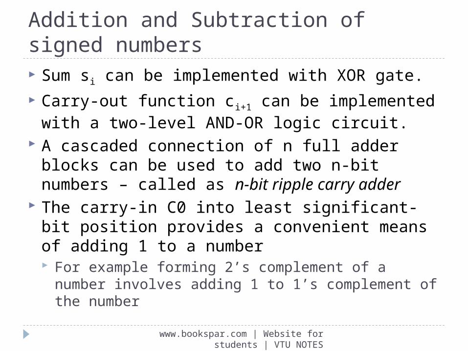
Addition and Subtraction of signed numbers Sum si can be implemented with XOR gate.
Carry-out function ci+1 can be implemented with a two-level AND-OR logic circuit.
A cascaded connection of n full adder blocks can be used to add two n-bit numbers – called as n-bit ripple carry adder
The carry-in C0 into least significant-bit position provides a convenient means of adding 1 to a number For example forming 2’s complement of a number
involves adding 1 to 1’s complement of the number
www.bookspar.com | Website for students | VTU NOTES
si =ci +1 =
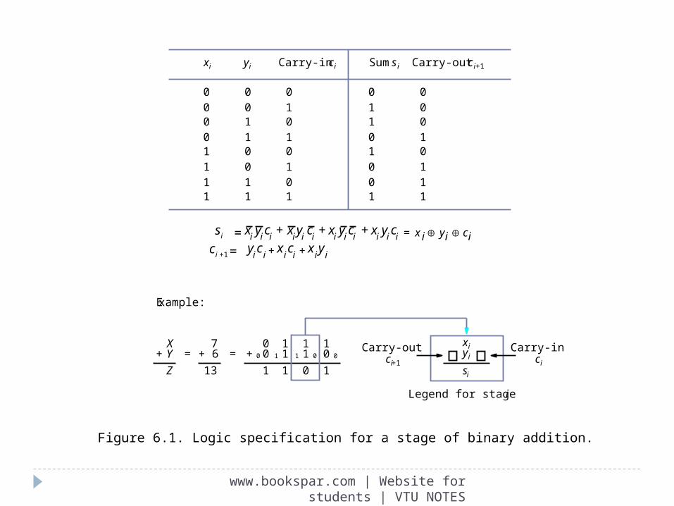
Figure 6.1. Logic specification for a stage of binary addition.
13
7+ Y
1
00010
1
1
00110
11
0
01101001
0
0
0
0
1
1
1
1
00001111
Example:
10= = 0
01 1
11 1 0 0
1
1 1 10
Legend for stage i
xi yi Carry-in ci Sum s i Carry-out ci+1
X
Z
+ 6 0+xiyisi
Carry-outci+1
Carry-inci
xiyicixiyicixiyicixiyici x i yi ci =+ + +
yicixicixiyi+ +
www.bookspar.com | Website for students | VTU NOTES
Full adder(FA)
c i
y ix i
c i 1+
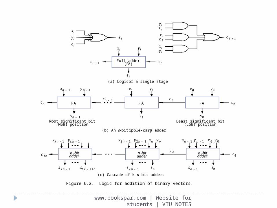
s i(a) Logic f or a single stage
FA c 0
y1x1
s 1
FAc 1
y0x0
s 0
FAc n 1-
y n 1-xn 1-
c n
s n 1-
(b) An n -bit r ipple-carr y adder
n -bit c 0
y nxn
s n
cn
y 0xn 1-
s0
c kn
s k 1- n
x 0y n 1-y2 n 1-x2 n 1-y k n 1-
s n 1-s 2 n 1-s k n 1-
(c) Cascade of k n-bit adders
x k n 1-
Figure 6.2. Logic for addition of binary vectors.
Most significant bit(MSB) position
Least significant bit(LSB) position
c i
y i
x ic i
y i
x i
x i
c i
y i s i c i 1+
addern -bitadder
n -bitadder
www.bookspar.com | Website for students | VTU NOTES
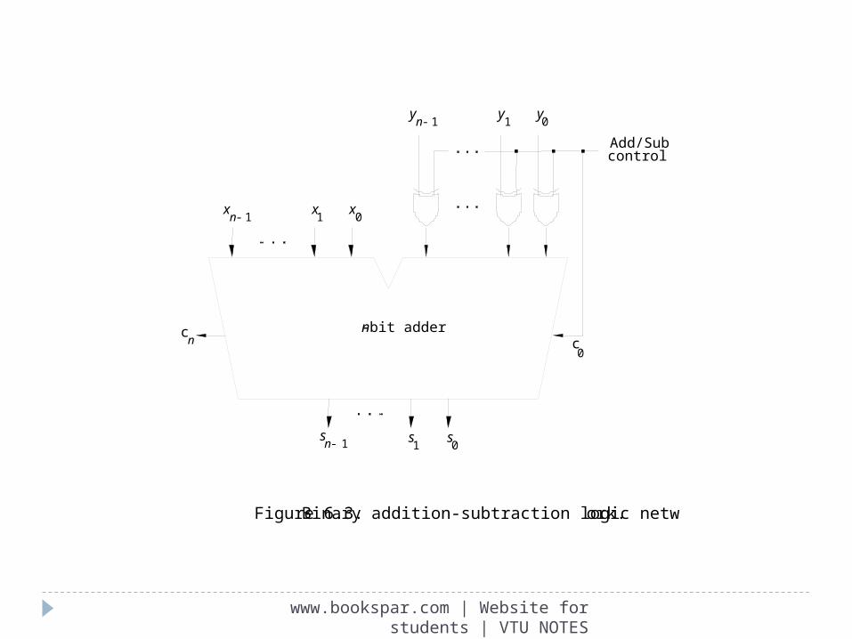
Add/Subcontrol
n -bit adder
xn 1-
x1
x0
cn
sn 1- s
1s0
c0
yn 1-
y1
y0
Figure 6.3. Binary addition-subtraction logic network.
www.bookspar.com | Website for students | VTU NOTES
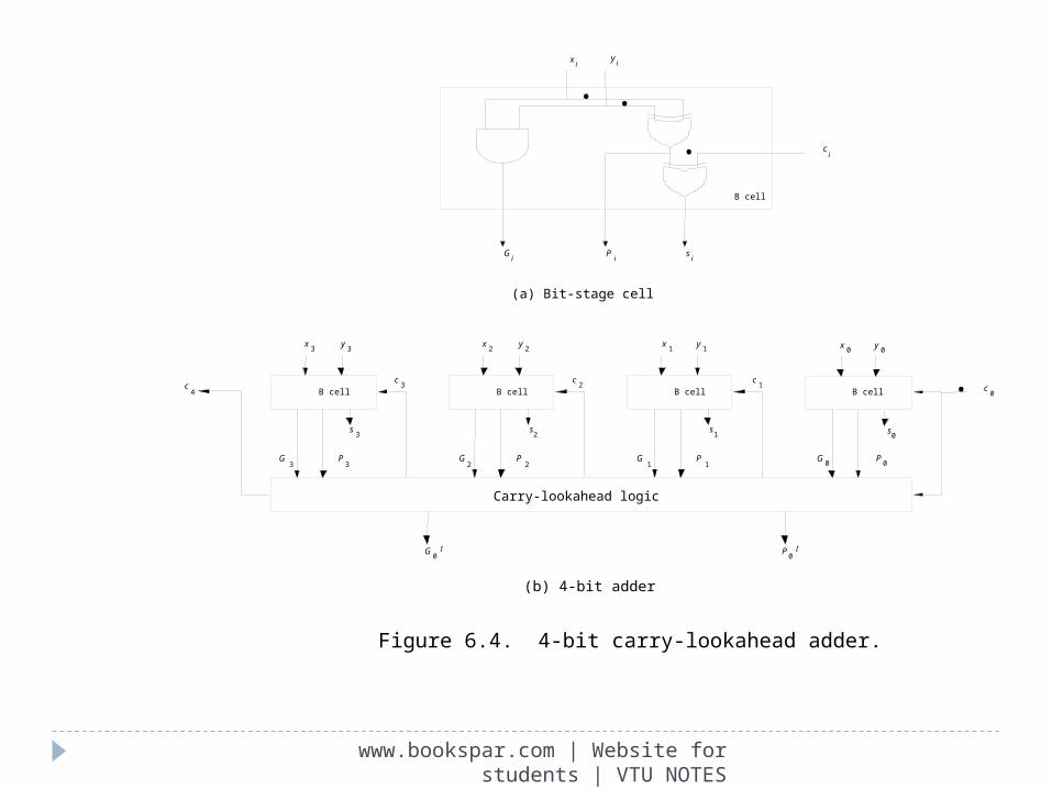
Figure 6.4. 4-bit carry-lookahead adder.
Carry-lookahead logic
B cell B cell B cell B cell
(b) 4-bit adder
(a) Bit-stage cell
s3
P3
G3
c3
P2
G2
c2
s2
G1
c1
P1
s1
G0
c0
P0
s0
.c4
x1
y1
x3
y3
x2
y2 x
0y
0
Gi
ci
..
.
Pi
si
xi
yi
G0I P
0I
B cell
www.bookspar.com | Website for students | VTU NOTES
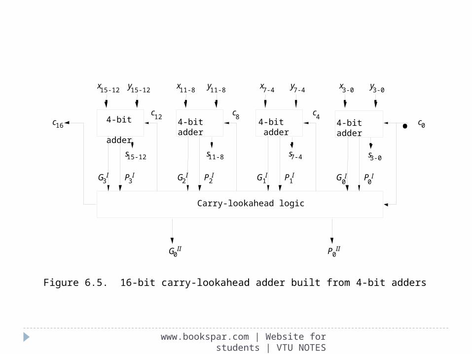
Figure 6.5. 16-bit carry-lookahead adder built from 4-bit adders
Carry-lookahead logic
4-bit adder
4-bit adder
4-bit adder
4-bit adder
s15-12
P3IG3
I
c12
P2IG2
I
c8
s11-8
G1I
c4
P1I
s7-4
G0I
c0
P0I
s3-0
c16
x15-12
y15-12
x11-8
y11-8
x7-4
y7-4
x3-0
y3-0
.
G0II P0
II
www.bookspar.com | Website for students | VTU NOTES
![COMPUTER ORGANIZATION Subject Code: 10CS46 - VTU Solutionvtusolution.in/.../cse-iii-computer__organization_[15cs34]-notes.pdf · COMPUTER ORGANIZATION 10CS46 . COMPUTER ORGANIZATION](https://static.fdocuments.in/doc/165x107/5b7970717f8b9a331e8dcaf3/computer-organization-subject-code-10cs46-vtu-15cs34-notespdf-computer.jpg)