Computer-Integrated Surgery and Medical Robotics
44
7/15/01 12:02 PM 1 of 44 chapter-final Computer-Integrated Surgery and Medical Robotics Russell Taylor (*) and Leo Joskowicz (**) (*) Department of Computer Science Center for Computer-Integrated Surgical Systems and Technology The Johns Hopkins University 3400 N. Charles Street Baltimore, Maryland 21218 USA [email protected] (**) School of Computer Science and Engineering Computer-Aided Surgery and Medical Image Processing Laboratory The Hebrew University of Jerusalem Jerusalem 91904, ISRAEL [email protected] 1. Introduction: coupling information to surgical action The growing demand for complex and minimally invasive surgical interventions is driving the search for ways to use computer-based information technology as a link between the pre-operative plan and the tools utilized by the surgeon. Computers, used in conjunction with advanced surgical assist devices, will fundamentally alter the way that are procedures are carried out in 21st Century operating rooms. Computer Integrated Surgery (CIS) systems make it possible to carry out surgical interventions that are more precise and less invasive than conventional procedures, while judiciously tracking and logging all relevant data. This data logging, coupled with appropriate tracking of patient outcomes, will make possible a totally new level of quantitative patient outcome assessment and treatment improvement analogous to “total quality management” in manufacturing. The goals of CIS systems are to enhance the dexterity, visual feedback, and information integration of the surgeon. While medical equipment is currently available to assist the surgeons in specific tasks, it is the synergy between these capabilities that gives rise to a new paradigm. The goal is to complement and enhance the surgeon's skills and always leave him in control, never to replace him. CIS systems are instances of an emerging paradigm of human-computer cooperation to accomplish delicate and difficult tasks. In some cases, the surgeon will supervise a CIS system that carries out a specific treatment step such as inserting a needle or machining bone. In other cases, the CIS system will provide information to assist the surgeon’s manual execution of a task, for example through the use of computer graphic overlays on the surgeon’s field of view. In some cases, these modes will be combined. From an engineering systems perspective, the objective can be defined in terms of two inter-related concepts:
Transcript of Computer-Integrated Surgery and Medical Robotics

7/15/01 12:02 PM 1 of 44 chapter-final
Computer-Integrated Surgery and Medical Robotics
Russell Taylor (* ) and Leo Joskowicz(* * )
(*) Department of Computer Science
Center for Computer-Integrated Surgical
Systems and Technology
The Johns Hopkins University
3400 N. Charles Street
Baltimore, Maryland 21218 USA
(**) School of Computer Science and Engineering
Computer-Aided Surgery and Medical Image
Processing Laboratory
The Hebrew University of Jerusalem
Jerusalem 91904, ISRAEL
1. Introduction: coupling information to surgical action The growing demand for complex and minimally invasive surgical interventions is driving the search
for ways to use computer-based information technology as a link between the pre-operative plan and the
tools utilized by the surgeon. Computers, used in conjunction with advanced surgical assist devices, will
fundamentally alter the way that are procedures are carried out in 21st Century operating rooms.
Computer Integrated Surgery (CIS) systems make it possible to carry out surgical interventions that
are more precise and less invasive than conventional procedures, while judiciously tracking and logging
all relevant data. This data logging, coupled with appropriate tracking of patient outcomes, will make
possible a totally new level of quantitative patient outcome assessment and treatment improvement
analogous to “ total quality management” in manufacturing.
The goals of CIS systems are to enhance the dexterity, visual feedback, and information integration of
the surgeon. While medical equipment is currently available to assist the surgeons in specific tasks, it is
the synergy between these capabilities that gives rise to a new paradigm. The goal is to complement and
enhance the surgeon's skills and always leave him in control, never to replace him.
CIS systems are instances of an emerging paradigm of human-computer cooperation to accomplish
delicate and difficult tasks. In some cases, the surgeon will supervise a CIS system that carries out a
specific treatment step such as inserting a needle or machining bone. In other cases, the CIS system will
provide information to assist the surgeon’s manual execution of a task, for example through the use of
computer graphic overlays on the surgeon’s field of view. In some cases, these modes will be combined.
From an engineering systems perspective, the objective can be defined in terms of two inter-related
concepts:

7/15/01 12:02 PM 2 of 44 chapter-final
� Surgical CAD/CAM systems transform preoperative images and other information into
models of individual patients, assist clinicians in developing an optimized interventional plan,
register this preoperative data to the patient in the operating room, and then use a variety of
appropriate means, such as robots and image overlay displays, to assist in the accurate
execution of the planned interventions.
� Surgical assistant systems work interactively with surgeons to extend human capabilities in
carrying out a variety of surgical tasks. They have many of the same components as surgical
CAD/CAM systems, but the emphasis is on intraoperative decision support and skill
enhancement, rather than careful pre-planning and accurate execution.
Two other concepts related to CIS are Surgical Total Information Management (STIM) and Surgical
Total Quality Management (STQM), which are analogous to “ total information management” and “ total
quality management” in manufacturing enterprises.
Table 1 summarizes some of the factors that must be considered in assessing the value of CIS systems
with respect to their potential application. Although the main focus of this article is the technology of
such systems, an appreciation of these factors is very important both in the development of practical
systems and in assessing the relative importance of possible research topics.
The CIS paradigm started to emerge from research laboratories in the mid 1980’s, with the introduction of
the first commercial navigation and robotic systems in the mid 1990’s. Since then, a few hundreds of CIS
systems have been installed in hospitals and are in routine clinical use, and a few tens of thousands of
patients have been treated with CIS technology, with their number rapidly growing. The main clinical
areas for which these systems have been developed are neurosurgery, orthopedics, radiation therapy, and
laparoscopy. Preliminary evaluation and short-term clinical studies indicate improved planning, execution
precision, which results in a reduction of complications and shorter hospital stays. However, some of
these systems have in some cases a steep learning curve and longer intraoperative times than traditional
procedures, indicating the need to improve them.
To make our discussion more concrete, we briefly present two examples of deployed CIS systems:
ROBODOC® (Integrated Surgical Systems, Davis, Ca.) an active medical robotics system, and the
StealthStation® (Medtronic Surgical Navigation Technology, Boulder, Colo.) an intraoperative navigation
system used in neurosurgery and orthopaedics.
The ROBODOC system [1-7] is active medical robot developed clinically by Integrated Surgical System
from a prototype developed at the IBM T.J. Watson Research Center in the late 1980’s (Figure 1).

7/15/01 12:02 PM 3 of 44 chapter-final
ROBODOC is a computer-integrated system for cementless primary total hip replacement. In primary
total hip replacement procedures, a damaged joint connecting the hip and the femur is replaced by a
metallic implant inserted into a canal broached in the femur. ROBODOC allows surgeons to plan
preoperatively the procedure by selecting and positioning an implant with respect to a Computer
Tomography (CT) study and intraoperatively mill the corresponding canal in the femur with a high-speed
tool controlled by a robotic arm. It consists of an interactive preoperative planning software, and an
active robotic system for intraoperative execution. Pre-clinical testing showed an order-of-magnitude
improvement in precision and repeatability in preparing the implant cavity. As of 2001, about 40 systems
were in clinical use, having performed an estimated 8,000 procedures, with very positive results
documented in follow-up studies.
The StealthStation [8] is representative of current surgical navigation systems (Figure 2). It allows
surgeons to intraoperatively visualize the relative locations of surgical tools and anatomy in real time and
perform surgical actions accordingly. The anatomical model used for navigation is constructed from
preoperative CT or MRI data. The instruments and rigid anatomy location are obtained in real time by
attaching to them frames with light-emitting diodes that are accurately tracked with a stereoscopic optical
tracking camera. The preoperative model is registered to the intraoperative situation by touching with a
tracked probe predefined landmarks or points on the anatomy surface and matching them to their
corresponding location on the model. Intraoperative navigation allows for less invasive surgery and more
precise localization without the need of repeated intraoperative X-ray or ultrasound two-dimensional
imaging. For example, to perform a biopsy of a tumor on the brain, the surgeon directs the instrumented
drill on the patient's skull with the help of the images, and drills directly towards the tumor instead of
making an incision on the skull and visually looking for the tumor.
The key technical enabling factors that lead the development of CIS systems were the increasing
availability of powerful imaging modalities, such as CT, MRI, NMT, and live video, powerful computers
with graphics capabilities, novel algorithms for model construction and navigation, and integrative
systems and protocol development. This article reviews the main technical issues of CIS systems. It is
organized as follows: the next section presents an overview of CIS systems, their main elements
architecture, and information flow. The following section describes the main enabling technologies of
CIS systems: imaging devices, image processing, visualization and modeling, preoperative analysis and
planning, registration, tracking and sensing, robotics, human-machine interfaces, and systems integration
technology. Then, we describe in detail examples of CIS systems including navigation systems,

7/15/01 12:02 PM 4 of 44 chapter-final
augmented reality navigation systems, and virtual reality systems. We conclude with perspectives and
possible directions for future development.
2. An overview of CIS systems Figure 3 shows a generic block diagram of a CIS system. At the core is a computer (or network of
computers) running a variety of modeling and analysis processes, including image and sensor processing,
creation and manipulation of patient-specific anatomical models, surgical planning, visualization,
monitoring and control of surgical processes. These processes receive information about the patient from
medical imaging devices about the patient and may directly act on the patient through the use of
specialized robots or other computer-controlled therapy devices. The processes also communicate with
the surgeon through a variety of visualization modules, haptic devices, or other human-machine
interfaces. The surgeon remains at all times in overall control of the procedure and, indeed, may do all of
the actual manipulation of the patient using hand tools with information and decision support from the
computer. The modeling and analysis processes within the computer will often rely upon databases of
prior information, such as anatomical atlases, implant design data, or descriptions of common surgical
tasks. The computer can also retain nearly all information developed during surgical planning and
execution, and store it for post-operative analysis and comparison with long term outcomes.
Essential elements of CIS systems are devices and techniques to provide the interfaces between the
“ virtual reality” of computer models and surgical plans to the “ actual reality” of the operating room,
patients, and surgeons. Broadly speaking, we identify three inter-related categories of interface
technology: 1) imaging and sensory devices; 2) robotic devices and systems; and 3) human-machine
interfaces. Research in these areas draws on a broad spectrum of “ core” engineering research disciplines,
including materials science, mechanical engineering, control theory, device physics, and others. The
fundamental challenge is to extend the sensory, motor, and human-adaptation abilities of computer-based
systems in a demanding and constrained environment. Particular needs include compactness, precision,
biocompatibility, imager compatibility, dexterity, sterility, and human factors.
Figure 4 illustrates the overall information flow of CIS systems from the surgical CAD/CAM
paradigm perspective. The CIS systems combine preoperative and intraoperative modeling and planning
with computer-assisted execution and assessment. The structure of the Surgical Assistant systems is
similar, except that many more decisions are made intraoperatively, since preoperative models and plans
may sometimes be relatively less important. Broadly speaking, surgery with a CIS system comprises
three phases, all drawing upon a common technology base.

7/15/01 12:02 PM 5 of 44 chapter-final
� Preoperative: phase: A surgical plan is developed from a patient-specific model generated from
preoperative images and a priori information about human anatomy contained in an anatomical
atlas or database. Planning is highly application-dependent since the surgical procedures are
greatly different. In some cases, it may be simple interactive simulations or the selection of some
key target positions, such as performing a tumor biopsy in neurosurgery. In other cases, such as in
craneofacial surgery, planning can require sophisticated optimizations incorporating tissue
characteristics, biomechanics, or other information contained in the atlas and adapted to the
patient-specific model.
� Intraoperative phase: The images, patient-specific model, and plan information are brought into
the operating room and registered to the patient, based on information from a variety of sensors,
usuch as a spatial tracking system and/or intraoperative imaging device. In some cases, the model
and plan may be further updated, based on the images. The computer then uses a variety of
interface devices to assist the surgeon in executing the surgical plan. Depending on what is most
appropriate for the application these interfaces may include active devices such as robots, “ smart”
hand tools, and information displays. As the surgery proceeds, additional images or other
measurements may be taken to assess progress and provide feedback for controlling tools and
therapy delivery. Based on this feedback, the patient model may be updated during the procedure.
This updated model may be used to refine or update the surgical plan to ensure that the desired
goals are met. Ideally, intraoperative imaging and other feedback can ensure that the technical
goals of the surgical intervention have been achieved before the patient leaves the operating room.
Further, the computer can identify and record a complete record of pertinent information about the
procedure without significant additional cost or overhead.
� Postoperative phase: The preoperative and intraoperative information are combined with
additional images and tests, both to verify the technical results of the procedure and to assess the
longer-term clinical results for the patient. Further, the results of many procedures may be
registered back to an anatomical atlas to facilitate statistical studies relating surgical technique to
clinical outcomes.
Note that the above description is of an idealized CIS system: specific systems do not necessarily require
all these capabilities, and some of them are beyond the current state of the art. However, we will use this
generic description to organize the technical discussion in the following section.
From a surgeon's perspective, the key difference between advanced medical equipment and a CIS system
is the information integration, both between phases and within each phase. This new capability requires in
most cases modifications to existing surgical protocols, and in a few cases radically new protocols. It

7/15/01 12:02 PM 6 of 44 chapter-final
could also enable more surgeons to perform certain difficult procedures that require much coordination
and knowledge available to only a few experienced specialists, or perform procedures that are currently
not feasible.
3. The technology of CIS systems
This section describes the main technical elements of CIS systems. We begin with a brief summary of
medical imaging devices, and then present methods for image processing, visualization, and modeling.
We describe next preoperative planning and analysis, followed by registration of data from various
sources. Then we discuss tracking and sensing, robotics, man-machine interfaces and systems integration
technology.
3.1 Medical imaging Medical images, both preoperative and intraoperative, are the main source of information of CIS systems.
Since they are used in all CIS systems, we briefly discuss their technical characteristics and typical uses.
We distinguish between preoperative and intraoperative imaging devices. Preoperative imaging devices,
such as film and digital X-rays, Computed Tomography (CT), Magnetic Resonance (MRI), and Nuclear
Magnetic Tomography (NMT) in various forms, are used to obtain images for diagnosis and surgical
planning. In most cases, the imaging devices are large and are located outside the surgical suite. Two-
dimensional film X-ray images are the most common, with superb spatial resolution, gray-value range,
and contrast, and negligible noise and geometric distortion. However, they are two-dimensional
projections of spatial structures, and are not amenable to processing for further use unless scanned. CT
and MRI images are used to visualize anatomical structures, with CT best suited for bony structures and
MRI best suited for soft tissue. They consist of a series of two-dimensional parallel cross-sectional
images with high spatial resolution, little geometric distortion and intensity bias, good signal to noise
ratio, and a wide field of view. Typical data sets consist of 80-150 images of size 512x512 12-bit gray
level pixel images with pixel size of 0.4x0.4mm at 1-2mm intervals. They can be used to visualize
anatomical structures, perform spatial measurements, and extract three-dimensional anatomical models.
NMT images show functional anatomy, such as nerve activity, and are mostly used in the brain. They
also consist of a series of two-dimensional parallel slices, although their quality is lower. They are
usually viewed in conjunction with MRI images. The main drawback of preoperative images is that they
are static and don't always reflect the position and orientation of anatomical structures which have moved
between the time the images were taken and the surgery is performed.

7/15/01 12:02 PM 7 of 44 chapter-final
Intraoperative imaging devices include fluoroscopic X-ray, ultrasound, and video image streams from
endoscopes, laparoscopes, and surgical microscopes. Fluoroscopic X-ray is widely used in orthopedics to
visualize and adjust the position of surgical instruments with respect to bones, or to locate kidney stones.
The images are obtained from a mobile C-arm unit, which allows capturing two dimensional projection
images from different viewpoints while the patient lies on the table. The circular images are usually
displayed on a video monitor. They have a narrow field of view (6 to 12” , 400 pixels in diameter),
limited spatial resolution and contrast, and present varying, position-dependent intensity and geometric
distortions. They are mostly used for qualitative evaluation, and have cumulative radiation as a side
effect. Ultrasound images (both static and as sequences) are used to obtain images of anatomy close to
the skin. Unlike X-ray images, they have no harmless radiation, but present significant imaging artifacts,
such as speckling, noise, and spatial distortion. They also have a narrow field of view and have the
resolution and image quality of the standard video monitor where they are displayed. Video image
streams became commonplace with the introduction of minimally invasive surgery in the 1980’s. They
are used to support tumor biopsies, gall bladder removals, and colon explorations, among many others.
They allow the surgeon to visualize in real time anatomy and surgical instruments inserted in a body
cavity. The limitations of these imaging devices are that they have a narrow field of view (about 3” ),
have no depth perception, uneven illumination, distortion due to the use of wide-angle lenses, and require
direct line of sight. Surgeons must learn how to move and point the camera while respecting various
point-of-entry and location constraints. The main advantage of intraoperative images is that they
provide an up-to-date image of the surgical situation. However, the field of view and image quality are
far inferior to preoperative images. More recent intraoperative imaging devices include surgical Open
MRI, surgical CT, and 3D ultrasound, which overcome some of the limitations of the more common
imaging devices.
The main limitation of current practice is that there is no quantitative correlation between high-quality
preoperative images and intraoperative images. The surgeon must mentally establish the spatial
correlation between the images and make decisions based on this correlation.
3.2 Image processing, visualization, and modeling
After image acquisition, the first task is usually visualization for diagnosis, evaluation, and planning. The
visualization can take place on displays other than those of the devices where they were acquired, and can
require various image processing techniques for better evaluation. These include image balancing and

7/15/01 12:02 PM 8 of 44 chapter-final
enhancement, distortion and contrast correction, de-noising, and spatial aggregation. For example,
individual two-dimensional X-ray and ultrasound images can be processed using an array of standard
image processing techniques to improve their clinical value. They can be visualized using zooming,
cropping, and other imaging techniques. They can also be combined to create new, multimodal images.
Visualization of CT, MRI, and nuclear medicine images can greatly benefit from specialized visualization
techniques, since they are series of two-dimensional cross sections. Instead of having the surgeon
mentally correlate consecutive slices and create a mental three-dimensional view, it is desirable to directly
reconstruct the three-dimensional information and show it as a new computed image. There are two
families of visualization algorithms: volume visualization and surface visualization. We describe them
briefly next.
Volume visualization algorithms [9] take as input slices and produce a three-dimensional image from any
desired viewpoint. The most common method of generating the three-dimensional images is ray casting
(Figure 5). The data set is viewed as a volumetric data set, in which the space is divided into small
volume units, called voxels. The voxels are rectangular blocks whose upper and lower faces are
consecutive slice pixels in the vertical direction, and whose height is the slice interval distance. To each
voxel is associated an intensity value, which is interpolated from the nearby pixel intensity values. To
obtain the three-dimensional image, rays emanating from the viewpoint’s location towards the image
plane are cast on the volume. The pixel intensities in the new image are computed according to an
attenuation function, which indicates how to compose the voxel intensity values that the ray traverses.
Different choices of attenuation function produce various effects, such as opaque bodies, semi-
transparency, or anatomy isolation according to predefined intensity ranges. For example, if only bony
surfaces are to be shown, only voxels whose intensity values are within the range of bone intensity are
considered in the attenuation function. The advantage of this method is its simplicity, as no previous
segmentation or surface extraction is necessary. However, it is computationally expensive, as hundreds
of thousands of voxels need to be examined for each new image. Various hardware (Z-buffering) and
software techniques (precomputed views, ray arrays) have been developed to speed up the rendering
process. Another disadvantage is that no model of the anatomy is created, restricting the type of analyses
that can be performed on it. Volume visualization is best suited for complex anatomy with fine details,
such as the brain gray matter.
Surface-based visualization algorithms rely on geometric surface models of the anatomy to be visualized.
The inputs are usually objects described as triangular meshes extracted from the original data representing

7/15/01 12:02 PM 9 of 44 chapter-final
the surface of the anatomical structures of interest, such as the skull, femur, kidneys, colon, etc. The
objects are then displayed as CAD models on viewers that can take advantage of standard graphics
hardware. The main advantage of surface-based visualization is that it has to handle smaller data sets and
is thus computationally much more efficient than volume visualization, allowing for near real-time
positioning and manipulation on standard computers. Another advantage is that CAD models of implants
and surgical instruments can be readily incorporated into the image. However, surface-based visualization
requires extracting the surface models, which can be difficult for complex anatomical structures with
many fine details and complex geometry. Surface-based algorithms are best suited for anatomy with
relatively large and clearly defined surfaces, such as bones and intestinal conduits.
Model construction algorithms are a prerequisite to surface-based visualization and for all tasks that
require a geometric model of the anatomy: preoperative planning, contour-based registration, anatomical
atlas construction and matching. Their input is a series of slices, and a predefined intensity threshold
interval that defines the image intensity ranges of the anatomy of interest. The output is one or more
triangular meshes describing the geometry of the surfaces. Mesh extraction algorithms can be divided
into two families: 2D contour extraction algorithms and 3D surface reconstruction algorithms. Contour
extraction algorithms work by segmenting (manually or automatically) the contour of the anatomy of
interest in each slice, and then connecting the resulting successive 2D contours to form a 3D surface. A
point p1 on the contour extracted in slice i is connected to the next point p2 on the same contour at a
predefined distance, and both are connected to the closest point p3 in slice i+1 to form a triangle p1p2p3
which represents a surface element. By alternating between consecutive slices, a triangulated ribbon is
created between the boundary contours. The drawback of this method is that ambiguities can arise as to
how point should be selected to create triangles, resulting in topologically inconsistent surfaces (holes,
self-intersections, etc).
To alleviate this problem, surface reconstruction algorithms work directly on the volumetric data to
identify the voxels, which are intersected by the object surface and determine its geometry. The most
commonly used algorithm in this category is the so-called “ marching cubes algorithm” [10]. The
algorithm proceeds as follows: a moving cube whose vertices are the pixels of two subsequent slices is
formed. The eight vertices of the cube have associated with it a binary number (0 or 1), which indicates if
the corresponding to pixel intensity value is above or below a pre-specified threshold (Figure 6). When
all eight vertices have a value of 0 (1), the voxel is entirely outside (inside) the anatomical object of
interest. Cubes with mixed values (one or more zero and one) are at the boundary of the object.
Depending on which vertex values are zero or one, one or more triangular surfaces cutting the cube can
7/15/01 12:02 PM 10 of 44 chapter-final
be constructed. There are 28 = 256 cases, which can be reduced by symmetry to 14 cases and stored in a
lookup table for reference. The algorithm proceeds by moving the cube from the topmost, upper corner
of the first two slices to the lowest, bottom corner of the last two slices in sequence. Depending on the
vertex values, the table is accessed and the corresponding triangles are constructed. The advantage of this
algorithm is its locality, and that the surfaces constructed are topologically consistent (ambiguities in
surface construction can be resolved locally). Variants of this algorithm include a tetrahedron instead of a
cube, for which there are only two cases with no ambiguities, but which produce two to five times more
triangles. The resulting meshes are typically several tens to several hundreds of thousands of triangles,
depending on the slice spacing on the original data set. Mesh simplification algorithms can then be
applied to the resulting models to reduce their complexity with minimal loss of accuracy.
While surface models are the most commonly used in CIS systems, they are by no means the only types
of models. Functional models, containing relevant information specific to an anatomical structure or
procedure can also be extracted with custom techniques. For example, a kinematic model of the lleg
bones and joints is of interest when planning a total knee replacement. To construct this model,
geometric entities such as the mechanical axis of the femur, the center of the femoral head, and other
anatomical landmarks should be extracted. Each surgical application requires the construction of its
model and the simulation associated with it.
Another type of model used in CIS is a digital atlas. Digital atlases are constructed from detailed imaging
data of a person and are used for visualization, planning, and educational purposes. An example of this
type of data is the Visible Human Project, which has detailed CT, MRI, and photographic data of a male
and a female. This data is carefully segmented and labeled, and a database of organs is constructed from
it. The model can then be inspected, for example using the VOXEL-MAN software [11], or used to
match to other patient data.
3.3 Preoperative analysis and planning Once the diagnosis has been made and it has been decided that surgery is necessary, the next step is to
carry preoperative analysis and elaborate a surgical plan of action. This plan can range from simple tasks
such as determining the access point of a biopsy needle, to complex gait simulations, implant stress
analysis, or radiation dosage planning. Because the analysis and planning is specific to each surgical
procedure and anatomy, preoperative planning and analysis software is usually custom to each clinical
application. These systems can be viewed as medical CAD systems, which allow the user to manipulate

7/15/01 12:02 PM 11 of 44 chapter-final
and visualize medical images, models of anatomy, implants, and surgical tools, perform simulations, and
elaborate plans. To give the reader an idea of the current scope of these systems, we will briefly describe
two planning systems, one for orthopaedics and one for radiation therapy.
In orthopaedics, planning systems are generally used to select implants and find their optimal placement
with respect to anatomy. For example, a planning system for spinal pedicle screw insertion shows the
surgeon three orthogonal cross-sections of the acquired CT image (the original xy slice and interpolated xz
and yz slices) and a three dimensional image of the vertebrae surfaces. The surgeon selects a screw type
and its dimensions, and positions it with respect to the anatomy in the three cross sectional views. A
projection of the screw CAD model is superimposed on the images, and its position and orientation with
respect to the viewing plane can be modified, with the result displayed in the other windows. Once a
satisfactory placement has been obtained, the system stores it with the screw information for use in the
operating room. Similar systems exist for total hip and total knee replacement, which, in addition,
automatically generate in some cases machining plans (cut files) for intraoperative surgical robots. Other
systems also extract kinematic or fine-element models and perform gait and stress analysis that help
surgeons estimate the effectiveness of the proposed solution.
Another example of a complex planning system is in the field of radiation therapy. The goal of radiation
therapy is to kill tumor cells by exposing them to a radiation beam while affecting as little as possible the
surrounding healthy cells. One way of achieving this is to expose the tumor cells to radiation beams from
different directions so that the cumulative radiation effect on the tumor cells destroys them while
preserving the surrounding healthy cells. The planning task consists of identifying the tumor and the
critical areas where no radiation should be present from MRI images, and then selecting the number of
beams, their radius, intensity, duration, and placement that maximizes the radiation to the tumor cells
while minimizing the radiation to other cells, especially those in the critical areas. This problem is
formulated as a geometric minimum-maximum constrained optimization problem, and solved with a
combination of geometric and non-linear optimization techniques. The planning system includes a data
visualization and volume definition module, and outputs a series of location commands to the robotic arm
carrying the radiation source, and the beam information at each location.

7/15/01 12:02 PM 12 of 44 chapter-final
3.4 Registration
Multimodal registration is one of the key steps for information integration in CIS systems. The goal of
the registration process is to allow the combination of data from several modalities, possibly taken at
different times, so that they can be viewed and analyzed jointly. Registering two data sets consists of
finding a transformation that aligns common features in two modalities, so that their spatial locations
coincide. Registration is necessary for many tasks such as:
� Combine information of the same patient taken with different modalities, such as CT and MRI,
MRI and PET � Combine information of the same patient before, during, and after surgery, such as preoperative
CT and intraoperative X-ray fluoroscopy, preoperative MRI and intraoperative video from a
microscope or an endoscope, CT or X-rays from before and after surgery � Create real-time virtual reality views of moving anatomy and surgical tools by matching
preoperative models from CFT or MRI with intraoperative tracking data � Perform a statistical study of patient data
Most CIS applications require more than one transformation to link two data sets, and thus have more
than one registration problem. For example, in the ROBODOC system, the preoperative plan has to be
registered to the intraoperative position of the bone so that the robot tip can machine the desired canal
shape in the planed position. To obtain this transformation, we must compute the transformation from the
bone coordinate system to the implanted fiducials, then from the fiducials to the robot tip, to the robot
coordinate system, and then to the cut volume. The series of mathematical transformations that align one
data set with another is called the registration chain.
The registration task is in fact not one but many different problems. There are great differences on
technical approaches depending on the type of data to be matched, the anatomy involved, and the clinical
and technical requirements of the procedure. There is a vast body of literature on registration, which is
comprehensively surveyed in [12, 13] and can be classified according to the following characteristics:
� Modalities: refers to the sources from which data is acquired, e.g. X-ray, CT, MRI, PET, video,
tracker, etc. The combinations can be unimodal (same data source) or multimodal (different data
sources), which can be two images, an image to a model, or an image to a patient (tracker data).

7/15/01 12:02 PM 13 of 44 chapter-final
� Dimensionality: refers to the spatial and temporal dimensions of the two data sets to be matched
(two or three-dimensional, static or time-varying). The registration dimensionality can be static
2D /2D (X-ray images), 2D/3D (ultrasound to MRI), 3D/3D (PET to MRI),or time-varying, such
as digital subtraction angiography (DSA).
� Registration basis: refers to the image features that will be used to establish the alignment. These
can be extrinsic registration objects, such as a stereotactic frame, or fiducials markers, or intrinsic,
such as anatomical landmarks, anatomical contours, or pixel intensity values.
� Nature and domain of mathematical transformation: refers to the type of mathematical
transformation that is used to perform the alignment. The transformation can be rigid, affine,
projective, or generally curved (deformable registration), and can be applied to parts of the image
(local) or to the entire image (global).
� Solution method: refers to how the transformation is computed. This can include direct solutions
when an analytic solution or an appropriate approximation is found, or iterative solutions, where
there is a search and numerical optimization methods are used.
� Type of interaction: refers to the type of input that the user has to supply. The registration is
interactive when it is performed entirely by the user, automatic when no user intervention is
required, or semi-automatic when the user supplies an initial estimate, helps in the data
segmentation, or steers the algorithm by accepting or rejecting possible solutions.
� Subject: refers to the patient source from which the images are taken: it can be the same patient
(intra-subject), two different patients (inter-subject), or a patient and an atlas.
� Anatomy: refers to the anatomy being imaged. This can be the head (brain, skull, teeth, nasal
cavities), the thorax (heart, breast, ribs), the abdomen (kidney, liver, intestines), the pelvis and the
perineum, or the limbs (femur, tibia, humerus, hand).
The main steps of registration algorithms are summarized in Table 3. Before attempting to match the
datasets, each data set should be corrected for distortions so that the errors resulting from imaging
artifacts do not affect the accuracy of the registration process. Next, what should be matched is identified
in each image. This can be point landmarks, contours, surfaces, pixel values and their gradients, or

7/15/01 12:02 PM 14 of 44 chapter-final
regions of interest. The pairwise correspondence between these is established so that a measure of
similarity between the data sets can be established. The more the features are apart, the larger the
dissimilarity is. The similarity is usually formulated as a constrained minimization problem whose
minimum is the transformation T that reduces the dissimilarity the most. If no closed form solution
exists, the local minimum is found by numerical optimization. One of the data sets is moved by the
transformation, and the process is repeated until the match is sufficiently good or no further improvement
is possible.
Technically, registration techniques can be classified as rigid or deformable, and geometry or intensity-
based. Rigid registration computes a transformation of position and orientation between two data sets. It
is applicable to rigid structures that change their position but not their shape, such as bones, implanted
fiducials and stereotactic frames, as an approximation to quasi-rigid structures, such as tumors or brain
white matter. It is also used as the first step of deformable registration, which computes a general global
or local curved map. Deformable registration is necessary for matching soft tissue organs (e.g., brain
images before and after brain shift) for time-dependent comparisons (e.g., tumor growth evaluation), and
for cross patient and atlas comparisons. The main difficulties of deformable registration are that the
problem is ill posed, since there are usually infinitely many transformations that match the data, and that
error measurements and comparisons are difficult. The geometric approach uses the spatial disparity
(usually the distance) between geometric entities, such as points, contours, or surfaces. The intensity-
based approach uses the pixel intensity values and the intensity gradient between pixels to maximize the
image correlation.
Examples of common registration tasks are: � Rigid geometric registration between a surface model obtained from preoperative CT and
intraoperative surface data on the same anatomy obtained by touching landmarks or collecting
sample points with a tracker. This method is widely used in CIS orthopaedics systems, such as
pedicle screw fixation, total hip and knee replacement, and trauma � Deformable intensity-based registration between brain MRI data sets before and after brain shift
3.5 Positional tracking and other sensing
An important feature of many CIS systems is the ability to accurately determine in real time the
location of selected anatomical structures, surgical instruments, and implants during surgery. This
information is necessary for visualization, navigation, and guidance. The component that delivers this
information to the CIS system is called a tracker or a localizer.

7/15/01 12:02 PM 15 of 44 chapter-final
There are many technologies available for positional tracking, including: encoded mechanical
linkages; acoustic tracking; electromagnetic tracking; optical tracking using specialized devices; and
optical tracking using conventional computer vision methods. Typically, these systems measure the
motion relative to some base device of individual elements (which we will call “ markers” ) attached to the
objects to be tracked. Several excellent surveys are available on this subject, including [14, 15]. Each
method has advantages and drawbacks. The main comparison parameters include setup requirements,
work volume characteristics, number of objects that can be tracked simultaneously, the update frequency,
the static and dynamic accuracy, the variability and repeatability of the readings, and cost.
Currently, the most commonly used position tracking approaches are based on specialized optical
devices such at the Optotrak® and Polaris® systems (Northern Digital, Waterloo, Canada) and Pixsys® and
FlashPoint® systems (Image Guided Technologies, Boulder, Colo.). These devices use two or more
optical cameras to identify light-emitting diodes or reflective markers in the camera image and compute
their location by stereo triangulation. They can be quite accurate, providing 3D localization accuracies
ranging from 0.1 mm to about 0.5 mm in typical applications. Their drawbacks include cost and the
necessity of maintaining a clear line-of-sight between the sensors and the markers. Magnetic tracking
systems such as the Polhemus® (Rockwell International, Milwaukee, Wis.), Flock-of-Birds® (Ascension
Technology, Burlington, Vt.) and Aurora® (Northern Digital, Waterloo, Canada) systems are also widely
used. These systems no not have line-of-sight constraints, but may be subject to field distortion from
materials in the operating room.
Force sensors are commonly used in medical robotic systems to measure and monitor tool-to-tissue
and tool-to-surgeon interaction forces (e.g., [16-21]). Generally speaking, the technology used in these
sensors is the same as that used in other applications, although specific issues of sterility and compactness
often present unusual design strategies.
More broadly, a very wide variety of sensors may be used to determine any number of local tissue
properties. Examples include electrical conductivity, optical coherence tomography, near infrared
sensing, and temperature sensing, to name a few.
3.6 Robotics
Medical robot systems have the same basic components as any other robot system: a controller, manipulators, end-effectors, communications interfaces, etc.). Many of the design challenges are familiar to anyone who has developed an industrial system. However, the unique demands of the surgical environment, together with the emphasis on cooperative execution of surgical tasks, rather than unattended automation, do create some unusual challenges.
Table 2 compares the strengths and weaknesses of humans and robots in surgical applications.

7/15/01 12:02 PM 16 of 44 chapter-final
Safety is paramount in any surgical robot, and must be given careful attention at all phases of system
design. Each element of the hardware and software should be subjected to rigorous validation at all
phases ranging from design through implementation and manufacturing to actual deployment in the
operating room. Redundant sensing and consistency checks are essential for all safety-critical functions.
Reliability experience gained with a particular design or component adapted from industrial applications
is useful but not sufficient or even always particularly relevant, since designs must often be adapted for
operating room conditions. It is important both to guard against both the effects of electrical, electronic,
or mechanical component failure and the more insidious effects of a perfectly functioning robot system
correctly executing an improper motion command caused by improper registration between the
computer’s model of the patient and the actual patient. Further excellent discussion may be found in [22,
23] and in a number of papers on specific systems.
Sterility is also a crucial concern. Usually, covering most of the robot with a sterile bag or drape and
then separately sterilizing the instruments or end-effectors provide sterility. Autoclaving, which is the
most universal and popular sterilization method, can unfortunately be very destructive for
electromechanical components, force sensors, and other components. Other common methods include
gas (slow, but usually kindest to equipment) and soaking.
Manipulator design is very important in medical robots. Several early systems (e.g., [24]) used
essentially unmodified industrial robots. Although this is perhaps marginally acceptable in a research
system that will simply position a guide and then be turned off before any contact is made with a patient,
any use of an unmodified robot capable of high speeds is inherently suspect. Great care needs to be taken
to protect both the patient and operating room personnel from run-away conditions. It is generally better
to make several crucial modifications to any industrial robot that will be used in surgery. These include:
� Installation of redundant position sensing; � Changes in gear ratios to slow down maximum end-effector speed; and � Thorough evaluation and possible redesign for electrical safety and sterility.
Because the speed/work volume design point for industrial and surgical applications are very different,
a more recent trend has emphasized design of custom manipulator kinematic structures for specific
classes of applications. Some examples may be found in [25-30].
Many surgical applications (e.g., in laparoscopy or neuroendoscopy) require surgical instruments to
pass through a narrow opening into the patient’s body. This constraint has led a number of groups to
consider two rather different approaches in designing robots for such applications. The first approach
(e.g., Figure 8 right, Figure 9, Figure 10 and Figure 12) and references [25, 26, 31, 32]) uses goniometers,

7/15/01 12:02 PM 17 of 44 chapter-final
chain drives, parallel 5-bar linkages, or other means to decouple instrument motions about an “ isocenter”
which is placed at the entry portal. The second approach (e.g. Figure 8 left and [33-35]) relies on passive
compliance to cause the surgical instrument to comply with the entry portal constraint. In this case, the
robot’s “ wrist” typically has two un-actuated, but encoded, rotary axes proximal to the surgical instrument
holder. Both approaches have merit, and they can be combined fruitfully, as described in [36]. The first
approach is usually more precise and provides a more stable platform for stereotactic procedures. The
second approach has the advantages of being simple and of automatically accommodating patient
motions. A fuller discussion of the tradeoff can be found in [36].
Surgical manipulators are not always active devices. Often, the human surgeon provides some or all
of the motive power, while the computer provides real time navigational or other assistance (e.g., [25, 27,
32, 37-39]).
Because medical robots are often used together with imaging, materials are also an important concern
in surgical manipulator design equipment (e.g., [27, 40]). Figure 10 shows one example of a simple 1-
degree-of-freedom radiolucent mechanism that can be used to drive needles into soft tissue [27]. This
device is designed for use with fluoroscopic x-rays or ct scanners, and it can be employed either with a
simple support clamp or as the end effector of an active robot. Fiducial geometry can be added easily to
the robot or end-effectors to assist in registration of the robot to the images (e.g., Figure 11 and also
references [41-45]).
Development of robotic devices for use with magnetic resonance imaging (MRI) poses special
challenges, because of the strong magnetic fields and RF signals involved. Figure 15 and Figure 16 show
two typical systems. Other examples include [40, 46].
3.7 Human-machine interfaces
Computer-based systems that work cooperatively with humans must communicate with them, both to
provide information and to receive commands and guidance. As with surgical robots, surgical human-
machine interfaces (HMI) have much in common with those for other application domains, and they draw
upon essentially the same technologies (speech, computer vision and graphics, haptics, etc.) that have
found use elsewhere. In many cases, HMI subsystems that have been developed for other uses may be
adapted with little change for surgical use. However, attention must be given to the unusual requirements
of surgical applications [47]. Surgeons tend to have very high expectations about system responsiveness
and transparency, but have very low tolerance for interfaces that impede their work. On the other hand, t
can also be quite willing to put up with great inconvenience if the system is really performing a useful
function that truly extends their capabilities.

7/15/01 12:02 PM 18 of 44 chapter-final
Surgeons overwhelmingly rely on vision as their dominant source of feedback during surgery. Indeed,
the explosion in minimal access surgery over the past decade has very largely been the result of the
availability of compact, high-resolution video cameras attached to endoscopic optics. In these cases, the
surgeon’s attention is naturally focused on a television monitor. In such cases, it is often possible for the
computer to add computer graphics, text, and other information to the video stream (e.g., [48, 49]).
Similarly, surgical navigation systems (e.g.,[8, 9, 45-52]) provide computer graphic renderings and
feedback based on tracked surgical instrument positions and preoperative images. The so-called “ virtual
fluoroscopy” systems (e.g., [58-61] ) show predicted x-ray projections based on intraoperative
fluoroscopic images and tracked instrument positions. One very important challenge in the design of such
systems is the providing useful information about the imprecision of the system’s information, so that the
surgeon does not make decisions based on a false determination of the relative position of a surgical
instrument and target anatomy. One common approach is to display a circle or ellipse representing likely
registration uncertainty, but significant advances are needed both in the modeling of such errors and in the
human factors associated with their presentation.
One limitation of video overlay systems is the limited resolution of current-generation video cameras.
This is especially important in microsurgical applications, where the structures being operated on are very
small, or in applications requiring very good color discrimination. Consequently, there is also interest in
so-called optical overlay methods in which graphic information is projected into the optical path of a
microscope (e.g., [62]) or presented on a half-silvered mirror (e.g., [63, 64]) so that it appears to be
superimposed on the surgeon’s field of view in appropriate alignment. The design considerations for
these systems are generally similar to those using video displays, but the registration problems tend to be
even more demanding and the brightness of the displays also an be a problem.
All of the common interfaces (mice, joysticks, touch screens, push-buttons, foot-switches, etc.) used
for interactive computer applications are used to provide input for surgical systems as well. For
preoperative planning applications, these devices are identical to those used elsewhere. For intraoperative
use, sterility, electrical safety, and ergonomic considerations may require some design modifications. For
example, the LARS robot [48] repackaged the pointing device from an IBM Thinkpad® computer into a 3
button “ mouse” clipped onto the surgeon’s instruments. As another example, a tracked stereotactic wand
has been used to provide a configurable “ push button” interface in which functions are selected by
tapping the tip of the pointer onto a sterilized template [65].
Surgeons routinely use voice to communicate with operating room personnel. Further, their hands
(and feet) are frequently rather busy. Accordingly, there has long been interest in using voice as a 2-way
command and control system for surgical applications. Examples include [35, 48, 66-68].

7/15/01 12:02 PM 19 of 44 chapter-final
Force and haptic feedback is often important for surgical simulation (e.g., [68, 69] and telesurgery
applications (e.g., [19, 21, 70-73]). Again, the technical issues involved are similar to those for other
virtual reality and telerobotics applications, with the added requirement of maintaining sterility and
electrical safety.
3.8 Systems Computer-Integrated Surgery is highly systems-oriented. Well engineered systems are crucial both for
use in the operating room and to provide context for the development of new capabilities. Safety,
usability and maintainability, and interoperability are the most important considerations. We discuss them
briefly next.
Safety is very important. Surgical system designs must be both safe, in the sense that system failures
will not result in significant harm to the patient and be perceived to be safe. Good system design typically
will require careful analysis of potential failure sources and the likely consequences of failures. This
analysis is application-dependent, and it is important to remember that Care must be taken to ensure that
system component failures will not go undetected and that the system will remain under control at all
times. Wherever possible, redundant hardware and software subsystems should be provided and
crosschecked against each other. Rigorous software engineering practices must be maintained at all
stages. Discussion of general safety issues for surgical robots may be found in [22, 74-77]. An excellent
case study of what can happen when good practices are ignored may be found in [78], which discusses a
series of accidents involving a radiation therapy machine.
Many discussions of safety in CIS systems tend to focus on the potential of active devices such as
robots or radiation therapy machines to do great harm if they operate in an uncontrolled manner. This is a
valid concern, but it should not be forgotten that such “ run away” situations are not usually the main
safety challenge in CIS systems. For example, both robotic and navigation assistance systems rely on the
accuracy of registration methods and the ability to detect and/or compensate for patient motion to ensure
that the surgical instruments do not stray from the targeted anatomy. A human surgeon acting on
incorrect information can place a screw into the spinal cord just as easily as a robot can. This means that
analysis software and sensing must be analyzed just as carefully as motion control. Surgeons must be
fully aware of the limitations as well as the capabilities of their systems and system design should include
appropriate means for surgeon “ sanity checking” of surgical actions.
System usability and maintainability are also important design considerations. Clearly, the ergonomic
design of the system from the surgeon’s perspective is important (e.g., [79, 80]). However, the interfaces
provided for the operating room staff that must set up the equipment, help operate it, and provide routine

7/15/01 12:02 PM 20 of 44 chapter-final
maintenance are also crucial both for safety and economic reasons. Similarly, CIS systems should
include interfaces to assist field engineers trouble-shoot and service equipment. In this regard, the ability
of computer-based systems to log data during use can be especially useful in post-failure analysis and in
scheduling preventative maintenance, as well as in providing data for improvement in surgical outcomes
and techniques. Although most systems make some use of such facilities, they are probably under-used
in present-day commercial systems.
System interoperability is currently a major challenge. Commonly accepted open standards permitting
different equipment to work together in a variety of settings are badly needed. Several companies have
proposed proprietary standards for use by alliances of vendors, and there has been some academic and
government-supported work to provide tool kits, especially in software. However, these efforts are still
very fragmented.
4. Examples of CIS Systems There are already a few dozen CIS systems available commercially or as prototypes in research
laboratories worldwide. Although it is not practical to present an exhaustive survey, this section describes
a few examples of integrated systems that use parts of the technology described above. For the purposes
of this overview, we distinguish between four types of systems:
1. Information enhancement systems
2. Robotic systems for precise preoperative plan execution
3. Robotic systems for human augmentation
4. Other robotic systems
Note that many real systems could logically fit in several of these categories.
4.1 Information Enhancement Systems The purpose of information enhancement systems is to provide the surgeon and his team with accurate,
up-to-date, and useful data and images during the surgery so that they can best develop and update their
plan of action and perform surgical actions. To achieve this goal, information enhancement systems
usually combine information from different modalities, such as preoperative CT and MRI data, real-time
tracking data of tools and anatomy, intraoperative images such as ultrasound and fluoroscopic X-ray
images, video sequences from endoscopic cameras and more. In some cases, such as virtual diagnostic
endoscopy, a simulated environment replaces the actual procedure. Information enhancement systems are
7/15/01 12:02 PM 21 of 44 chapter-final
by far the most commonly used CIS systems. What distinguishes them from other CIS systems is that it
is the surgeon that performs all surgical gestures without any physical assistance from mechanical
devices.
We classify information enhancement systems into three categories:
1. Navigation systems
2. Augmented reality navigation systems
3. Virtual reality systems
We describe them briefly next.
4.1.1 Navigation systems
The purpose of intraoperative navigation systems is to provide surgeons with up-to-date, real time
information about the location of surgical tools and selected anatomy during surgery. The goal is to
improve the surgeon’s hand/eye coordination and spatial perception, thereby improving the accuracy of
the surgical gestures. They support less invasive procedures, can shorten surgery time, and can improve
outcomes.
The basic elements of a navigation system are: (1) a real-time tracking system to follow one or more
moving objects (anatomy, surgical tools, or implants); (2) tracking-enabled tools and reference frames;
(3) a display showing the intraoperative situation; and (4) a computer to integrate the information (Figure
2). Since the patient is usually not immobilized, a dynamic reference frame is attached to the anatomy to
correct the relative position of the tools to the images.
What is displayed depends on the type of images that are available. The navigation systems can be based
on: � Preoperative images, such as CT or MRI augmented with CAD models of tools and implants. � Intraoperative images, such as fluoroscopic X-ray, ultrasound, or open MR images augmented
with projections of tool CAD models and implant axes. � Intraoperative video streams from an endoscopic camera or a surgical microscope, shown
alongside or fused with preoperative CT or MRI images

7/15/01 12:02 PM 22 of 44 chapter-final
Navigation systems based on preoperative CT or MRI images are typically used as follows: shortly before
surgery, a preoperative CT or MRI study of the anatomy of interest is acquired. In some cases, fiducial
markers that will be used for registration are attached to the patient skin or implanted to the anatomy so
that they appear in the images. The data is downloaded to a computer and a model of the anatomy is
created. When there are fiducials, they are identified and their precise relative spatial location is
computed. The surgeon can visualize the data and elaborate the surgical plan. Before the surgery starts,
the preoperative data, model, and plan are downloaded to the computer in the operating room. A dynamic
reference frame is attached to the patient, and the intraoperative situation is registered with the
preoperative data by either touching the fiducials with a tracked tool, or by acquiring a cloud of points on
the surface of the anatomy. Once the registration has taken place, a display showing the preoperative
images and model with the CAD models of the tools superimposed is created based on the current tool
and anatomy position obtained from the tracker (Figure 17). Several commercial systems are currently
available for a variety of procedures. Clinical studies report millimetric accuracy on tool and implant
positioning. These types of systems have been applied extensively in orthopaedics, (the spine (e.g., [58,
81, 82]), pelvis (e.g., [83, 84], fractures (e.g., [85-89], hip (e.g., [56, 90, 91]), and knee (e.g., [57, 92-94]),
neurosurgery, and craneofacial and maxillofacial surgery.
Navigation systems based on intraoperative images combine intraoperative images with position data
from surgical tools and implants to create augmented intraoperative views. An example of such system is
the FluoroNav system, which uses fluoroscopic X-ray images [61]. During surgery, a tracking device is
attached to the fluoroscopic C-arm, and one or more images are acquired with it. Projections of the tools
are then superimposed on the original images and updated in real time as the tools move (Figure 18).
Since the camera and the tools are tracked simultaneously, there is no need for registration. The
advantages of these systems are that they do not require a preoperative study and that no registration is
necessary. However, the views remain two-dimensional, requiring the surgeon to mentally recreate the
spatial intraoperative situation. Recent clinical studies show that these systems are having excellent
acceptance, since they are closest to current practice, and beginning to be used successfully [95].
Other navigation systems combine video stream data obtained from endoscopic cameras or surgical
microscopes, with data from preoperative studies, such as CT or MRI. The camera is tracked, so its
position and orientation during surgery are known and can be shown, after registration, together with the
preoperative images. The video stream can be shown side by side with a preoperative study, as in Figure
19, or selected information from it can be inserted in the video stream. The main advantage of these

7/15/01 12:02 PM 23 of 44 chapter-final
systems is that they allow surgeons to see beyond the surfaces shown in the video and to obtain spatial
location information that overcomes the narrow field of view of the cameras [96].
4.1.2 Augmented reality navigation systems
One of the drawbacks of the navigation systems described above is that they require the surgeon to
constantly shift his attention from the patient to the computer display and back. Augmented reality
navigation systems attempt to overcome this drawback by bringing the display right where the surgeon
needs it. The data is viewed through glasses worn by the surgeon, projected directly on the patient, or
displayed on a transparent screen standing between the surgeon and the patient. The surgeon’s head is
usually tracked, so that the data can be displayed from the correct viewpoint.
Two examples of this type of systems are the augmented reality CIS system for neurosurgery [97] and the
CMU image overlay system [63] for orthopaedics. The augmented reality CIS system for neurosurgery
projects colored segmented volumetric data of brain tumors and other neural structures directly on the
patient’s skull (Figure 20). This allows the surgeon to directly see where to start the minimally invasive
procedure. The HipNav navigation system was developed to assists orthopaedic surgeons in positioning
the acetabular cup in total hip replacement surgery. In this system, a transparent glass that serves as a
projection screen is placed between the surgeon and the patient on the operating table. After registration,
the hip and pelvis models extracted from the preoperative CT data are projected on the glass screen,
thereby providing the surgeon with X-ray like view of what lies beneath.
4.1.3 Virtual reality diagnosis systems
The third type of information enhancing systems is virtual reality diagnosis systems. These systems,
typically used in diagnostic endoscopy and colonoscopy, replace an actual exploration on the patient with
a virtual exploration on MRI images. A three-dimensional reconstruction of the anatomical structures of
interest, typically tube-like, is constructed from the data set, and a fly-through inspection path inside the
structure is computed. The clinician is then presented with a virtual movie that simulates the actual
endoscopic exploration (Figure 21). Based on these images, the clinician can look for and identify certain
pathologies, such as tumors, and then determine if an actual examination or surgery is necessary. Several
algorithms have been developed for model construction, fast visualization, and computation of fly-
through path [98].

7/15/01 12:02 PM 24 of 44 chapter-final
4.2 Robotic systems for precise preoperative plan execution
One of the drawbacks of navigation systems is that they cannot guarantee that a planned surgical gesture,
such as screw placement or needle insertion, will be executed precisely as planned. To ensure not only
precise positioning but also precise execution, surgical robots have been developed. We describe next two
examples of the most common types of active surgical robots: the ROBODOC® system discussed earlier,
and the LARS robot for percutaneous therapy.
4.2.1 Robotic orthopaedic surgery
Because bone is rigid and relatively easy to image in CT, and because geometric precision is often an
important consideration in orthopaedic surgical procedures, orthopaedic surgery has been an important
domain for the development of CIS systems. For example, the ROBODOC® system discussed earlier has
been in clinical use since 1992 and combines CT-based preoperative planning with robotic machining of
bone. Both ROBODOC and a very similar subsequently introduced system called CASPAR®
[99] have been
applied to knee surgery [100-102], as well as hip surgery. Other robotic systems have been proposed or
(in a few cases) applied for hip or knee surgery include [38, 39, 103-107].
These applications fit naturally within the context of surgical CAD/CAM systems. For example,
Figure 22 shows the information flow for the current ROBODOC implementation. The information flow
in the CASPAR system is very similar. CT images of the patient’s bones are read into a planning
workstation and a simple segmentation method is used to produce an accurate surface model of key
anatomical areas. After some key anatomical measurements are made from the images, the surgeon
selects an implant design from a library and determines its desired placement in the patient by
manipulating a CAD model of the implant with respect to selected mutually orthogonal cross-sections
through the CT data volume. The planning workstation computes a cutter trajectory relative to CT
coordinates and all of the planning information is written to a magnetic tape along with the patient images
and model.
In the operating room, robotic hip replacement surgery proceeds much as manual surgery until after
the head of the femur (for the case of primary hip surgery) or failing implant (for revision surgery) is
removed. Then the femur is fixed to the base of the robot and a redundant position sensor is attached to
the bone to detect any slipping of the bone relative to the fixation device. Then a 3D digitizer is used to
locate a number of points on the bone surface. These points are used to compute the coordinate
transformation between the robot and CT images used for planning and (thus) to the patient’s bone. The
surgeon then hand-guides the robot to an approximate initial position using a force sensor mounted
between the robot’s tool holder and the surgical cutter. The robot then cuts the desired shape while

7/15/01 12:02 PM 25 of 44 chapter-final
monitoring cutting forces, bone motion, and other safety sensors. The surgeon also monitors progress and
can interrupt the robot at any time. If the procedure is paused for any reason, there are a number of error
recovery procedures available to permit the procedure to be resumed or restarted at one of several defined
checkpoints. Once the desired shape has been cut, surgery proceeds manually in the normal manner. The
procedural flow for robotic knee replacement surgery is quite similar.
4.2.2 Robotically-assisted percutaneous therapy
One of the first uses of robots in surgery was positioning of needle guides in stereotactic neurosurgery
[24, 108, 109]. This is a natural application, since the skull provides rigid frame-of-reference. However,
the potential application of localized therapy is much broader. Percutaneous therapy fits naturally within
the broader paradigm of Surgical CAD/CAM systems. The basic process involves planning a patient-
specific therapy pattern, delivering the therapy through a series of percutaneous access steps, assessing
what was done, and using this feed-back to control therapy at several time scales. The ultimate goal of
current research is to develop systems that execute this process with robotic assistance under a variety of
widely available and deployable image modalities, including ultrasound, x-ray fluoroscopy, and
conventional MRI and CT scanners.
Current work at Johns Hopkins University is typical of this activity. Our approach has emphasized the
use of “ remote center-of-motion” (RCM) manipulators to position needle guides under real-time image
feedback. One early experimental system [110, 111], shown in Figure 23, was used to establish the
feasibility of inserting radiation therapy seeds into the liver under biplane x-ray guidance. In this work,
small pellets were implanted preoperatively and located in CT images used to plan the pattern of therapy
seeds. The fiducial pellets were relocated in the biplane x-rays and used to register the preoperative plan
to a modified LARS robot [112, 113] used to.implant the treatment seeds. Although this experiment and
related work directed at placing needles into the kidney [114, 115] established the basic feasibility of our
approach, we concluded that significant improvements in the robot would be needed
Subsequent work has focused on development of a modular family of very compact component
subsystems and end-effectors that could be configured for use in a variety of imaging and surgical
environments. Figure 10 shows a novel RCM linkage with a radiolucent needle driver (“ PAKY” )
developed by Stoianovici et al. that form key components in this next generation system. Figure 11
shows the RCM device with a novel end-effector developed by Susil and Masamune that permits the
computer to determine the needle pose to be computed with respect to a CT or MRI scanner using a single
image slice [42, 44, 45]. This arrangement can have significant advantages in reducing set-up costs and
time for in-scanner procedures and also eliminates many sources of geometric error. Figure 24 shows

7/15/01 12:02 PM 26 of 44 chapter-final
another variation of the RCM used as a high dexterity wrist in a system designed for manipulating
ultrasound probes for diagnosis and ultrasound-guided biopsies [116].
Related work at Brigham and Women’s Hospital in Boston is illustrated in Figure 16. This system
[117] is designed to operate in an open-magnet MRI system and uses a common control architecture
developed jointly by MIT, Brigham and Women’s Hospital, and Johns Hopkins [118, 119]. One early
application will be MRI-guided prostate therapy. Figure 15 shows another MRI-compatible robot system,
this one designed for breast biopsy [120].
4.3 Robotic systems for human augmentation
The emphasis in surgical assistant robots is the use of these systems cooperatively to enhance human
performance or efficiency in surgery. Much of the past and current work on surgical augmentation (e.g.,
[67, 70, 73, 121-125]) has focused on teleoperation. There is considerable interest in the use of master-
slave manipulator systems to improve the ergonomic aspects of laparoscopic surgery. Figure 25 shows a
typical example (the DaVinci® system [122] marketed by Intuitive Surgical). In this case, three slave
robots are used. One holds an endoscopic camera and two others manipulate surgical instruments. In the
case of the DaVinci, the surgical instruments have high dexterity wrists, as shown in Figure 25 (right).
Other systems with varying degrees of complexity (e.g., the Zeus® system marketed by Computer
Motion) are also in use, and this area of application may be expected to grow in the future.
Although the primary impact of teleoperated robots in surgical applications over the next years will
probably be in applications in which the surgeon remains close to the patient, there has also been
considerable interest in remote telesurgery (e.g., [70, 126, 127]). In addition to the design issues
associated with local telesurgery, these systems must cope with the effects of communication delays and
possible interruptions on overall performance.
The manipulation limitations imposed by human hand tremor and limited ability to feel and control
very small forces, together with the limitations of operating microscopes have led a number of groups to
investigate robotic augmentation of microsurgery. Several systems have been developed for teleoperated
microsurgery using a passive input device for operator control. Guerrouad and Vidal [128] describe a
system designed for ocular vitrectomy in which a mechanical manipulator was constructed of curved
tracks to maintain a fixed center of rotation. A similar micromanipulator [129] was used for acquiring
physiological measurements in the eye using an electrode. While rigid mechanical constraints were
suitable for the particular applications in which they were used, the design is not flexible enough for
general purpose microsurgery and the tracks take up a great deal of space around the head. An
ophthalmic surgery manipulator built by Jensen et al. [130] was designed for retinal vascular

7/15/01 12:02 PM 27 of 44 chapter-final
microsurgery and was capable of positioning instruments at the surface of the retina with sub-micron
precision. While a useful experimental device, this system did not have sufficient range of motion to be
useful for general-purpose microsurgery. Also, the lack of force sensing prevented the investigation of
force/haptic interfaces in the performance of microsurgical tasks.
Many microsurgical robots (e.g., [70, 124, 131-133]) are based on force-reflecting master-slave
configurations. This paradigm allows an operator to grasp the master manipulator and apply forces.
Forces measured on the master are scaled and reproduced at the slave and, if unobstructed, will cause the
slave to move accordingly. Likewise, forces encountered by the slave are scaled and reflected back to the
master. This configuration allows position commands from the master to result in a reduced motion of the
slave and for forces encountered by the slave to be amplified at the master.
While a force-reflecting master-slave microsurgical system provides the surgeon with increased
precision and enhanced perception, there are some drawbacks to such a design. The primary disadvantage
is the complexity and cost associated with the requirement of providing two mechanical systems, one for
the master and one for the slave. Another problem with telesurgery in general is that the surgeon is not
allowed to directly manipulate the instrument used for the microsurgical procedure. While physical
separation is necessary for systems designed to perform remote surgery, it is not required during
microsurgical procedures. In fact, surgeons are more likely to accept assistance devices if they are still
allowed to directly manipulate the instruments.
The performance augmentation approach pursued by the CIS group at Johns Hopkins University,
which has also been explored independently by Davies, et al. [37-39], and which has some resemblances
to the work of Kazerooni [134], emphasizes cooperative manipulation, in which the surgeon and robot
both hold the surgical tool. The robot senses forces exerted on the tool by the surgeon and moves to
comply. Our initial experiences with this mode in ROBODOC indicated that it was very popular with
surgeons and offered means to augment human performance while maximizing the surgeon’s natural
hand-eye coordination within a surgical task. Subsequently, we incorporated this mode into the
IBM/JHU LARS system [26, 36, 49, 135-139]. Figure 21 shows one early experiment using the LARS to
evacuate simulated hematomas with a neuroendoscopic instrument [54, 140-142]. We found that the
surgeon took slightly longer (6 vs. 4 minutes) to perform the evacuation using the guiding, but evacuated
much less surplus material (1.5% excess vs. 15%).
More recently, we have been exploring the extension of these ideas into microsurgery and other
precise manipulation tasks. We have extended our model of cooperative control, which we call “ steady
hand” guiding, to permit the compliance loop to be closed based on a scaled combination of forces
exerted by the surgeon and tissue interaction forces, as well as based on other sensors such as visual

7/15/01 12:02 PM 28 of 44 chapter-final
processing. The result is a manipulation system with the precision and sensitivity of a machine, but with
the manipulative transparency and immediacy of hand-held tools for tasks characterized by compliant or
semi-rigid contacts with the environment [18]. We have also begun to develop higher levels of control for
this system, incorporating more complex behaviors with multiple sensing modalities [72, 143-146], using
microsurgical tasks drawn from the fields of ophthalmology and otology. Figure 22 shows a typical
experiment using our current robot to evaluate robot-assisted stapedotomies. Figure 23 shows a
comparison of instrument tremor and drift with and without robotic assistance. We have also
demonstrated 30:1 scaling of forces in compliant manipulation tasks.
4.4 Other robotic assistants The use of robotic systems to assist surgeons by performing routine tasks such as laparoscopic camera
manipulation is becoming commonplace. Examples include [33, 35, 135, 147]. Some of the manipulator
design issues associated with such systems were discussed in Section 3.6. For human-machine interfaces,
these systems provided a joystick or foot pedal to permit the surgeon to control the motion of the
endoscope. However, other interfaces have include voice, tracking of surgeon head movements,
computer vision tracking of surgical instruments, indication of desired gaze points by manipulating a
cursor on the computer screen, etc. Figure 8 (left) shows a typical installation of a voice-controlled
commercial system (the AESOP(TM, developed by Computer Motion, Inc.).
More recently, there has been interest in robotic systems for manipulating ultrasound probes [116,
148-151]. Figure 12 and Figure 24 show typical current research efforts in development of such robotic
systems. Most of this activity has targeted diagnostic procedures such as systematic examination of
carotid arteries for occlusions. However, these systems have the potential to become as ubiquitous as the
robotic endoscope holders discussed above. Our research group at Johns Hopkins University has begun
to explore applications such as precise ultrasound-guided biopsies and other interventional procedures.
There has also been work in the use of flexible robotic devices for intralumenal applications such as
colonoscopy and angioplasty. Examples include [152-155] Generally, these devices are snake-like,
though there have been a few efforts (e.g., [155]) to develop autonomous crawlers.
5. Perspectives Computer-integrated surgery is a new, rapidly evolving paradigm that will change the way surgery
will be performed in the future. Technical advances in medical imaging, tracking, robotics, and
integration are paving the way to a new generation of systems for minimally invasive surgery.

7/15/01 12:02 PM 29 of 44 chapter-final
We believe that computer-integrated surgery (CIS) will have the same impact on health care in the
coming decades that computer-integrated manufacturing has had on industrial production in the recent
past. Achieving this vision will require both significant advances in basic engineering knowledge and the
development of robust, flexible systems that make this knowledge usable in real clinical application.
It is important to remember that the ultimate payoff for CIS systems will be in improved and more
cost-effective health care. Quantifying these advantages in practice can be problematic, and sometimes
the final answer may take years to be demonstrated. The consistency, enhanced data logging, and
analysis made possible by CIS systems may help in this process. It will not be easy to figure out how to
apply these capabilities. However, we believe that the CIS paradigm is here to stay.
6. Acknowledgments Any survey or critical summary must necessarily draw upon the work of many people. We would like
especially to acknowledge the contributions of many colleagues over the past decade who have helped
develop an evolving shared understanding of medical robotics and computer-integrated surgery. We are
especially grateful to those individuals who generously provided photographs and other information about
the specific systems that we have used as examples. In some cases, these colleagues have also worked
with us in developing some of these systems.
We also gratefully acknowledge the many agencies and organizations that have contributed financial
and other support to the development of much of the work that we have reported. The National Science
Foundation’s support of the Engineering Research Center for Computer-Integrated Surgical Systems and
Technology under cooperative agreement number EEC9731478. Further support has been provided by
other NSF grants, the National Institutes of Health, the Whitaker Foundation, IBM Corporation,
Integrated Surgical Systems, The Johns Hopkins University, and numerous other Government, Industry,
and Academic sources. We also acknowledge the partial support of the Israeli Ministry of Trade and
Industry, through the IZMEL Consortium for Image-Guided Therapy.
7/15/01 12:02 PM 30 of 44 chapter-final
7. References 1. Taylor, R.H., et al., An Image-directed Robotic System for Precise Orthopaedic Surgery. IEEE
Transactions on Robotics and Automation, 1994. 10(3): p. 261-275. 2. Mittelstadt, B.D., et al. The Evolution of a Surgical Robot from Prototype to Human Clinical
Trial. in Proc. Medical Robotics and Computer Assisted Surgery. 1994. Pittsburgh. 3. Paul, H., et al. Accuracy of Implant Interface Preparation: Hand-held Broach vs. Robot Machine
Tool. in Proc. Orthopaedic Research Society. 1992. Washington D.C. 4. Joskowicz, L. and R.H. Taylor. Preoperative Insertability Analysis and Visualization of Custom
Hip Implants. in 1st International Symposium on Medical Robotics and Computer Assisted Surgery. 1994. Pittsburgh.
5. Bauer, A. Primary THR Using the ROBODOC System. in CAOS/USA '99. 1999. Pittsburgh, Pennsylvania, USA.
6. Joskowicz, L., et al. Computer Integrated Revision Total Hip Replacement Surgery: Preliminary Report. in Second Annual International Symposium on Medical Robotics and Computer Assisted Surgery. 1995. Baltimore, MD.
7. Taylor, R.H., et al., Computer-Integrated Revision Total Hip Replacement Surgery: Concept and Preliminary Results. Medical Image Analysis, 1999. 3(3): p. 301-319.
8. Smith, K.R., K.J. Frank, and R.D. Bucholz, The Neurostation - a highly accurate minimally invasive solution to frameless stereotactic neurosurgery. Comput. Med. Inaging Graph., 1994. 18: p. 247-256.
9. Levoy, M., Efficient ray tracing of volume data. ACM Transactions on Graphics, 1990(9): p. 245-261.
10. Lorensen, W.E. and H.E. Cline, Marching Cubes: a high resolution 3D surface reconstruction algorithm. Computer Graphics, 1987. 21: p. 163-169.
11. Hohne, K.H., M. Bomans, and M. Reimer, A 3D anatomical atlas based on a volume model. IEEE Computer Graphics and Applications, 1992. 2(1): p. 72-78.
12. Lavallee, S., Registration for Computer-Integrated Surgery: Methodology, State of the Art, in Computer-Integrated Surgery, R.H. Taylor, et al., Editors. 1996, MIT Press: Cambridge, Mass. p. 77-98.
13. Maintz, J.B. and M.A. Viergever, A survey of medical image registration. Medical Image Analysis, 1998. 2(1): p. 1-37.
14. Reinhardt, H.F., Neuronagivation: A ten years review, in Computer-Integrated Surgery, R. Taylor, et al., Editors. 1996, MIT Press: Cambridge. p. 329-342.
15. Maciunas, R.J., Interactive Image-Guided Neurosurgery. 1993: American Association of Neurological Surgeons.
16. Taylor, R.H., et al., eds. An Image-Directed Robotics System For Precise Orthopaedic Surgery. Computer-Integrated Surgery, Technology and Clinical Applications, ed. R.H. Taylor. 1995. 379-396.
17. Taylor, R.H., et al., eds. Computer-Integrated Surgery, Technology and Clinical Applications. . 1995, The MIT Press.
18. Taylor, R., et al., A Steady-Hand Robotic System for Microsurgical Augmentation. International Journal of Robotics Research, 1999. 18(12).
19. Howe, R.D., et al., Remote Palpation Technology. IEEE Engineering in Medicine and Biology, 1995: p. 318-323.
20. Glucksberg, M.R. and R. Dunn, Direct measurement of retinal microvascular pressures in the live, anesthetized cat. Microvascular Research, 1993. 45(2): p. 158-65.

7/15/01 12:02 PM 31 of 44 chapter-final
21. Berkelman, P.J., et al. A miniature Instrument Tip Force Sensor fo rRobot/Human Cooperative Microsurgical Manipulation with Enhanced Force Feedback. in Medical Image Computing and Computer-Assisted Interventions. 2000. Pittsburgh: Springer.
22. Taylor, R.H., Safety, in Computer-Integrated Surgery, R.H. Taylor, et al., Editors. 1996, MIT Press: Cambridge, Mass. p. 283-286.
23. Davies, B.L., A discussion of safety issues for medical robots, in Computer-Integrated Surgery, R.H. Taylor, et al., Editors. 1996, MIT Press: Cambridge, Mass. p. 287-298.
24. Kwoh, Y.S., Hou. J., and E.A. Jonckheere, et. al., A robot with improved absolute positioning accuracy for CT guided stereotactic brain surgery. IEEE Trans Biomed Eng, 1988. 35(2): p. 153-161.
25. Nathan, M.S., et al. Devices for Automated Resection of the Prostate. in Proc. 1st International Symposium on Medical Robotics and Computer Assisted Surgery. 1994. Pittsburgh.
26. Eldridge, B., et al., A Remote Center of Motion Robotic Arm for Computer Assisted Surgery. Robotica, 1996. 14(1 (Jan-Feb)): p. 103-109.
27. Stoianovici, D., et al. An efficient needle injection technique and radiological guidance method for percutaneous procedures. in First Joint Conference: CRVMed II & MRCAS III, March. 1997. Grenoble, France.
28. Erbse, S., et al. Development of an automated surgical holding system based on ergonomic analysis. in Proc. First Joint Conference of CVRMed and MRCAS. 1997. Grenoble, France: Springer.
29. Grace, K.W., et al. Six degree of freedom micromanipulator for ophthalmic surgery. in IEEE Int. Conf. Robotics and Automation. 1993. Atlanta, GA: IEEE.
30. Brandt, G., et al. A compact robot for image-guided orthopaedic surgery: concept and preliminary results. in Proc. First Joint Conference of CVRMed and MRCAS. 1997. Grenoble, France: Springer.
31. Neisius, B., P. Dautzenberg, and R. Trapp. Robotic Manipulator for Endoscopic Handling of Surgical Effectors and Cameras. in Proc. Medical Robotics and Computer Assisted Surgery. 1994. Pittsburgh.
32. Taylor, R.H., et al. A Model-Based Optimal Planning and Execution System with Active Sensing and Passive Manipulation for Augmentation of Human Precision in Computer-Integrated Surgery. in Proc. 1991 Int. Symposium on Experimental Robotics. 1991. Toulouse, France: Springer-Verlag.
33. Sackier, J.M. and Y. Wang, Robotically Assisted Laparoscopic Surgery: from Concept to Development, in Computer-Integrated Surgery, R. Taylor, et al., Editors. 1996, MIT Press: Cambridge, Mass. p. 577-580.
34. Wang, Y. Robotically Enhanced Surgery. in Medicine Meets Virtual Reality II. 1994. Sandiego. 35. Hurteau, R., et al. Laparoscopic Surgery Assisted by a Robotic Camerman: Concept and
Experimental Results. in IEEE Conference on Robotics and Automation. 1994. San Diego. 36. Funda, J., et al. Comparison of two mainpulator designs for laparoscopic surgery. in 1994 SPIE
Int's Symposium on Optical Tools for Manufacturing and Advanced Automation. 1994. Boston: October.
37. Troccaz, J., M. Peshkin, and B.L. Davies. The use of localizers, robots, and synergistic devices in CAS. in Proc. First Joint Conference of CVRMed and MRCAS. 1997. Grenoble, France: Springer.
38. Ho, S.C., R.D. Hibberd, and B.L. Davies, Robot Assisted Knee Surgery. IEEE EMBS Magazine Sp. Issue on Robotics in Surgery, 1995(April-May): p. 292-300.
39. Harris, S.J., et al. Experiences with robotic systems for knee surgery. in Proc. First Joint Conference of CVRMed and MRCAS. 1997. Grenoble, France: Springer.
40. Masamune, K., et al. A newly developed stereotactic robot with detachable driver for neurosurgery. in Proc. 2nd Int. Symp. on Medical Robotics and Computer Assisted Surgery (MRCAS). 1995. Baltimore, Md.: MRCAS '95 Symposium, C/O Center for Orthop Res, Shadyside Hospital, Pittsburgh, Pa.

7/15/01 12:02 PM 32 of 44 chapter-final
41. Taylor, R.H., et al., Computer-Integrated Revision Total Hip Replacement Surgery: Concept and Preliminary Results. Medical Image Analysis, 1999. 3(3): p. 301-319.
42. Susil, R.C., J.H. Anderson, and R.H. Taylor. A Single Image Registration Method for CT Guided Interventions. in 2nd Int Symposium on Medical Image Computing and Computer-Assisted Interventions (MICCAI99). 1999. Cambridge, England: Springer.
43. Yao, J., et al., A C-arm fluoroscopy-guided progressive cut refinement strategy using a surgical robot. Computer Aided Surgery, 2000. 5(6): p. pp 373-390.
44. Masamune, K., et al. Development of CT-PAKY frame system - CT image guided needle puncturing manipulator and a single slice registration for urological surgery. in Proc. 8th annual meeting of JSCAS. 1999. Kyoto.
45. Masamune, K., et al., CT image guided Needle puncturing manipulator and a single slice registration for needle placement therapy. Journal of Computer Aided Surgery, 2000. In Review.
46. Masutani, Y., et al. Computer Aided Surgery (CAS) System for Stereotactic Neurosurgery. in Proc. Computer Vision and Robotics in Medicine (CVRMED). 1995. Nice, France: Springer.
47. --------, Human-Machine Interfaces, in Computer-Integrated Surgery, R.H. Taylor, et al., Editors. 1996, MIT Press: Cambridge, Mass. p. 201-254.
48. Taylor, R.H., et al., A Telerobotic Assistant for Laparoscopic Surgery, in Computer-Integrated Surgery, R. Taylor, et al., Editors. 1996, MIT Press. p. 581-592.
49. Funda, J., et al. Image Guided Command and Control of a Surgical Robot. in Proc. Medicine Meets Virtual Reality II. 1994. San Diego.
50. Adams, L., et al., CAS - A Navigation Support for Surgery, in 3d Imaging in Medicine. 1990, Springer-Verlag: Berlin Heidelberg. p. 411-423.
51. Kosugi, Y., et al., "An Articulated Neurosurgical Navigation System Using MRI and CT Images". IEEE Transactions on Biomedical Engineering, 1988. February: p. 147-152.
52. Watanabe, E., T. Watanabe, and S. Manka, et. al., Three-dimensional digitizer (neuronavigator): new equipment for computed tomography-guided stereotaxic surgery. Surg Neurol, 1987. 27: p. 543-547.
53. Cutting, C.B., F.L. Bookstein, and R.H. Taylor, Applications of Simulation, Morphometrics and Robotics in Craniofacial Surgery, in Computer-Integrated Surgery, R.H. Taylor, et al., Editors. 1996, MIT Press: Cambridge, Mass. p. 641-662.
54. Auer, L.M. Virtual Endoscopy for Planning and Simulation of Minimally Invasive Neruosurgery. in Proc. First Joint Conference of CVRMed and MRCAS. 1997. Grenoble, France: Springer.
55. Bucholz, R.D., et al., Intraoperative Localization Using a Three Dimensional Optical Digitizer, in Proceedings Medical Robotics and Computer Assisted Surgery. 1994, Shadyside Hospital: Pittsburgh.
56. DiGioia, A.M., et al., HipNav: Pre-operative Planning and Intra-operative Navigational Guidance for Acetabular Implant Placement in Total Hip Replacement Surgery. Computer Assisted Orthopedic Surgery, 1996.
57. Picard, F., et al. Computer-assosted navigation for knee arthroplasty: intra-operative measurements of alignment and soft tissue balancing. in First Annual Meeting of CAOS International. 2001. Davos.
58. Nolte, L.P., et al. Use of C-arm for Surgical Navigation in the Spine. in CAOS/USA'98. 1998. Pittsburgh, PA, USA.
59. Hofstetter, R., et al. Principles of Precise Fluoroscopy Based Surgical Navigation. in 4th International Symposium on CAOS. 1999. Davos, Switzerland.
60. Hofstetter, R., et al. Fluoroscopy based surgical navigation-concept and clinical applications. in Proceedings of Computer Assisted Radiology and Surgery. CAR '97. 1997. Berlin, Germany: Elsevier; Amsterdam, Netherlands.
61. Hofstetter, R., et al., Fluoroscopy as an imaging means for computer-assisted surgical navigation. Computer-Aided Surgery, 1999. 4(2): p. 65-76.

7/15/01 12:02 PM 33 of 44 chapter-final
62. N. Hata, W.M.W., M. Halle, S. Nakajima, P. Viola, R. Kikinis, F.A. Jolesz. Image guided microscopic surgery system using mutual information based registration. in VBC. 1996. Hamburg, Germany.
63. Blackwell, M., et al., An Image Overlay System for Medical Data Visualization. Medical Image Analysis, 2000. 4(1): p. 67-72.
64. Masamune, T., et al. Three dimensional slice image overlay system with accurate depth perception for surgery0. in Medical Image Computing and Computer-Assisted Intervention~-- MICCAI 2000. 2000. Pittsburgh: Springer.
65. Nolte, L.P. and H. Visarius, et al, Computer Assisted Orthopaedic Surgery. 1996: Hofgrefe & Huber.
66. Uecker, D.R., et al. A Speech-Directed Multi-Modal Man-Machine Interface for Robotically Enhanced Surgery. in First Int. Symp. on Medical Robotics and Computer Assisted Surgery (MRCAS 94). 1994. Pittsburgh: Shadyside Hospital.
67. Reichenspurner, H., et al., Use of the voice controlled and computer-assisted surgical system zeus for endoscopic coronary artery surgery bypass grafting. J. Thoracic and Cardiovascular Surgery, 1999. 118(1).
68. Confer, R.G. and R.C. Bainbridge. Voice control in the microsurgical suite. in Proc. of the Voice I/O Systems Applications Conference '84. 1984. Arlington, Va.: American Voice I/O Society.
69. d'Aulignac, D., R. Balaniuk, and C. Laugier. A haptic interface for a virtual exam of the human thigh. in IEEE Conf. on Robotics and Automation. 2000. San Francisco.
70. Mitsuishi, M., et al. A Telemicrosurgery System with Colocated View and Operation Points and Rotational-force-feedback -free Master Manipulator. in Proc. 2nd Int. Symp. on Medical Robotics and Computer Assisted Surgery. 1995. Baltimore, Md.: MRCAS '95 Symposium, C/O Center for Orthop Res, Shadyside Hospital, Pittsburgh, Pa.
71. Howe, R.D. and M.R. Cutkosky, Dynamic Tactile Sensing: Perception of Fine Surface Features with Stress Rate Sensing. IEEE Trans. Robotics & Automation, 1993. 9(2): p. 140-151.
72. Kumar, R., et al. Preliminary Experiments in Cooperative Human/Robot Force Control for Robot Assisted Microsurgical Manipulation. in IEEE Conference on Robotics and Automation. 2000. San Francisco.
73. Green, P. Telepresence Surgery. in NSF Workshop on Computer Assisted Surgery. 1993. Washington, D.C.
74. Taylor, R., et al. Redundant Consistency Checking in a Precise Surgical Robot. in 12'th Annual Conference on Engineering in Medicine and Biology. 1990. Philadelphia: IEEE Press.
75. Taylor, R., et al. Taming the Bull: Safety in a Precise Surgical Robot. in Intl. Conf. on Advanced Robotics (ICAR). 1991. Pisa, Italy.
76. B. Davies, A Discussion of Safety Issuesn for Medical Robots, in Computer-Integrated Surgery, R. Taylor, et al., Editors. 1996, MIT Press: Cambridge, Mass. p. 287-296.
77. Varley, P., Techniques of development of safety-related software in surgical robots. IEEE Trans. on Information Technology in Biomedicine, 1999. 3(4): p. 261-267.
78. Levensen, N.G. and C.S. Turner, An investigation of the Therac-25 accidents. Computer, 1993. 26(7): p. 18-41.
79. Rau, G., et al., Aspects of Ergonomic System Design Applied to Medical Work Stations, in Computer-Integrated Surgery, R.H. Taylor, et al., Editors. 1996, MIT Press: Cambridge, Mass. p. 203-222.
80. Sheridan, T., Human Factors in Telesurgery, in Computer-Integrated Surgery, R.H. Taylor, et al., Editors. 1996, MIT Press: Cambridge, Mass. p. 223-230.
81. Merloz, P., et al. Computer-assisted versus manual spine surgery: clinical report. in Proc. First Joint Conference of CVRMed and MRCAS. 1997. Grenoble, France: Springer.
82. Nolte, L.P., et al. A Novel Approach to Computer Assisted Spine Surgery. in First Int. Symp. on Medical Robotics and Computer Assisted Surgery (MRCAS 94). 1994. Pittsburgh: Shadyside Hospital.

7/15/01 12:02 PM 34 of 44 chapter-final
83. vanHellenMondt, G., M. deKleuver, and P. Pavlov. Computer assisted pelvic osteotomies; clinical experience in 25 cases. in First Annual Meeting of CAOS International. 2001. Davos.
84. Arand, M., L. Kinzl, and F. Gebhard. CT-based navigation in iminimal invasive screw stabilization of the iliosacral joint. in First Annual Meeting of CAOS International. 2001. Davos.
85. Joskowicz, L., et al., FRACAS: A System for Computer-Aided Image-Guided Long Bone Fracture Surgery. Journal of Computer Assisted Surgery, 1999.
86. Tockus, L., et al. Computer-Aided Image-Guided Bone Fracture Surgery: Modeling, Visulization, and Preoperative Planning. in MICCAI'98. 1998. Canbridge, MA, USA.
87. Verheyden, A., et al. Percutaneous stabilization of dorsal pelvic ring fractures -- transiliosacral screw placement in the open MRI. in First Annual Meeting of CAOS International. 2001. Davos.
88. Grutzner, P., et al. Computer-aided recuction and fixation of long bone fractures. in First Annual Meeting of CAOS International. 2001. Davos.
89. Suhm, N., et al. Computer assisted distal locking of intramedullary implants: a controlled clinical study including 84 patients. in First Annual Meeting of CAOS International. 2001. Davos.
90. DiGioia, A.M., B. Jaramaz, and R.V. O'Toole. An Integrated Approach to Medical Robotics and Computer Assisted Surgery in Orthopaedics. in Proc. 1st Int. Symposium on Medical Robotics and Computer Assisted Surgery. 1994. Pittsburgh.
91. Digioia, A., et al. Clinical Measurements of Acetabular Component Orientation Using Surgical Navigation Technologies. in First Annual Meeting of CAOS International. 2001. Davos.
92. Kunz, M., et al. Development and verification of an non-CT based total knee arthroplasty system for the LCS prosthesis. in First Annual Meeting of CAOS International. 2001. Davos.
93. Stulberg, S.D., P. Loan, and V. Sarin. Computer-Assisted Total Knee Replacement Surgery: An Analysis of an Initial Experience with the Orthopilot (TM) System. in First Annual Meeting of CAOS International. 2001. Davos.
94. Saragaglia, D., et al. Computer-Assisted Total Knee Replacement Arthroplasty: comparison with a conventional procedure. results of a 50 cases prospective randomized trial. in First Annual Meeting of CAOS International. 2001. Davos.
95. Wirth, S., E. Euler, and L. P. C-arm based computed tomography: a comparative study. in Proc. of the 15th Conf. on Computer-Aided Radiology and Surgery. 2001. Berlin, Germany: Elsevier.
96. Shahidi, R., Advances in video laparoscopic surgery using three-dimensional image enhanced endoscopy. MDVista Journal, 2000. May: p. 56-65.
97. Grimson, W.E.L., et al., An automatic registration method for frameless stereotaxy, image guided surgery and enhanced reality visualization. IEEE Trans on Medical Imaging, 1996. 15(2): p. 129-140.
98. Ecke, U., et al., Virtual Reality: preparation and execution of sinus surgery. Computer-Aided Surgery, 1998. 4(2): p. 45-50.
99. Peterman, J., et al. Implementation of the CASPAR System in the reconstruction of the ACL. in CAOS/USA. 2000. Pittsburgh: Shadyside Hospital.
100. Wiesel, U., et al. Total Knee Replacement Using the Robodoc System. in Proc. First Annual Meeting of CAOS International. 2001. Davos.
101. Tenbusch, M., et al. First results using the Robodoc system for total knee replacement. in First Annual Meeting of CAOS International. 2001. Davos.
102. Mai, S., C. Lorke, and W. Siebert. Motivation, Realization, and First Results of Robot Assisted Total Knee Arthroplasty. in Proc.. 1st Annual Meeting of CAOS International. 2001. Davos.
103. Garbini, J.L., et al. Robotic Instrumentation in Total Knee Arthroplasty. in Proc. 33rd Annual Meeting, Orthopaedic Research Society. 1987. San Francisco.
104. Fadda, M., et al. Computer-Assisted Knee Arthroplasty at Rizzoli Institutes. in Proc. 1st International Symposium on Medical Robotics and Computer Assisted Surgery. 1994. Pittsburgh.
105. Kienzle, T.C., et al. An integrated CAD-robotics system for total knee replacement surgery. in Proc. IEEE Int. Conf. on Robotics and Automation. 1993. Atlanta.

7/15/01 12:02 PM 35 of 44 chapter-final
106. Leitner, F., et al. Computer-assisted knee surgical total replacement. in Proc. First Joint Conference of CVRMed and MRCAS. 1997. Grenoble, France: Springer.
107. Marcacci, S., et al., Computer-Assisted Knee Arthroplasty, in Computer-Integrated Surgery, R.H. Taylor, et al., Editors. 1996, MIT Press: Cambridge, Mass. p. 417-423.
108. Cinquin, P., et al., IGOR: Image Guided Operating Robot. Innovation et Technonogie en Biologie et Medicine, 1992: p. 374-394.
109. Lavallee, S., et al., Image-Guided Operating Robot: A Clinical Application in Stereotactic Neurosurgery, in Computer-Integrated Surgery, R.H. Taylor, et al., Editors. 1996, MIT Press: Cambridge, Mass. p. 343-352.
110. Bzostek, A., et al. A Testbed System for Robotically Assisted Percutaneous Pattern Therapy. in Medical Image Computing and Computer-Assisted Surgery. 1999. Cambridge , England: Springer.
111. Schreiner, S., et al. A system for percutaneous delivery of treatment with a fluoroscopically-guided robot. in Joint Conf. of Computer Vision, Virtual Reality, and Robotics in Medicine and Medical Robotics and Computer Surgery. 1997. Grenoble, France.
112. Taylor, R., et al. An Experimental System for Computer Assisted Endoscopic Surgery. in IEEE Satellite Symposium on Neuroscience and Technoloy. 1992. Lyons: IEEE Press.
113. Taylor, R.H., et al., A Telerobotic Assistant for Laparoscopic Surgery, in IEEE EMBS Magazine Special Issue on Robotics in Surgery. 1995. p. 279-291.
114. Bzostek, A., et al. An automated system for precise percutaneous access of the renal collecting system. in Proc. First Joint Conference of CVRMed and MRCAS. 1997. Grenoble, France: Springer.
115. Caddedu, J.A., et al., A Robotic System for Percutaneous Renal Access. Urology, 1997. 116. Goldberg, R., A Robotic System for Ultrasound Image Acquisition, . 1999, Johns Hopkins
University: Baltimore. 117. Chinzei, K., et al. MR Compatible Surgical Assist Robot: System Integration and Preliminary
Feasibility Study. in Proceedings of Third International Conference On Medical Robotics, Imaging and Computer Assisted Surgery. 2000. Pittsburgh.
118. Bzostek, A., et al. Distributed Modular Computer-Integrated Robotic Systems" Implementation using modular software and networked systems. in Medical Image Computing and Computer-Assisted Interventions. 2000. Pittsburgh: Springer.
119. Schorr, O., et al. Distributed Modular Computer-Integrated Robotic Systems" Architecture for Intelligent Object Distribution. in Medical Image Computing and Computer-Assisted Interventions. 2000. Pittsburgh: Springer.
120. Kaiser, W.A., et al., Robotic system for biopsy and therapy of breast lesions in a high-field whole-body magnetic resonance tomography unit. J. Investigative Radiology, 2000. 35(8): p. 513-519.
121. Green, P., et al. Mobile Telepresence Surgery. in Proc. 2nd Int. Symp. on Medical Robotics and Computer Assisted Surgery. 1995. Baltimore, Md.: MRCAS '95 Symposium, C/O Center for Orthop Res, Shadyside Hospital, Pittsburgh, Pa.
122. Guthart, G.S. and J.K. Salisbury. The Intuitive Telesurgery System: Overview and Application. in Proc. of the IEEE International Conference on Robotics and Automation (ICRA2000). 2000. San Francisco.
123. Charles, S., R.E. Williams, and B. Hamel, Design of a Surgeon-Machine Interface for Teleoperated Microsurgery. Proc. of the Annual Int'l Conf. of the IEEE Engineering in Medicine and Biology Society, 1989: p. 11:883-884.
124. Salcudean, S.E., S. Ku, and G. Bell. Performance measurement in scaled teleoperation for microsurgery. in First joint conference computer vision, virtual realtiy and robotics in medicine and medical robotics and computer-assisted surgery. 1997. Grenoble, France: Springer.

7/15/01 12:02 PM 36 of 44 chapter-final
125. Ku, S. and S.E. Salcudean. Dexterity enhancement in microsurgery using a motion-scaling system and microgripper. in IEEE Int. Conf. on Systems, Man and Cybernetics. 1995. Vancouver, BC, Canada: IEEE.
126. Satava, r., Robotics, telepresence, and virtual reality: A critical analysis fo the future of surgery. Minimally Invasive Therapy, 1992. 1: p. 357-363.
127. Lee, B.R., Bishoff, J.T., Micali, S., Whitcomb, L.L., Taylor, R.H., Kavoussi, L.R. Robotic Telemanipulation for Percutaneous Renal Access. in 16th World Congress On Endourology. 1998. New York.
128. Guerrouad, A. and P. Vidal, S.M.O.S.: Stereotaxical Microtelemanipulator for Ocular Surgery. Proc. of the Annual Int'l Conf. of the IEEE Engineering in Medicine and Biology Society, 1989: p. 11:879-880.
129. Pournaras, C.J., et al., New ocular micromanipulator for measurements of retinal and vitreous physiologic parameters in the mammalian eye. Exp Eye Res, 1991. 52: p. 723-727.
130. Jensen, P.S., et al., Toward robot assisted vascular microsurgery in the retina. Graefes Arch Clin Exp Ophthalmol, 1997. 235(11): p. 696-701.
131. Charles, S., Dexterity enhancement for surgery. Proc First Int'l Symp Medical Robotics and Computer Assisted Surgery, 1994. 2: p. 145-160.
132. Hunter, I.W., et al., Ophthalmic microsurgical robot and associated virtual environment. Computers in Biology and Medicine, 1995. 25(2): p. 173-182.
133. Schenker, P.S., H.O. Das, and R. Timothy. Development of a new high-dexterity manipulator for robot-assisted microsurgery. in Proceedings of SPIE - The International Society for Optical Engineering: Telemanipulator and Telepresence Technologies. 1995. Boston, MA.
134. Kazerooni, H. and G. Jenhwa, Human extenders. Transaction of the ASME: Journal of Dynamic Systems, Measurement and Control, 1993. 115(2B): p. 218-90, June.
135. Taylor, R.H., et al., Telerobotic assistant for laparoscopic surgery. IEEE Eng Med Biol, 1995. 14(3): p. 279-288.
136. Funda, J., et al., Constrained Cartesian motion control for teleoperated surgical robots. IEEE Transactions on Robotics and Automation, 1996.
137. Funda, J., et al. Control and evaluation of a 7-axis surgical robot for laparoscopy. in Proc 1995 IEEE Int. Conf. on Robotics and Automation. 1995. Nagoya, Japan: IEEE Press.
138. Funda, J., et al. An experimental user interface for an interactive surgical robot. in 1st International Symposium on Medical Robotics and Computer Assisted Surgery. 1994. Pittsburgh.
139. Funda, J., et al. Optimal Motion Control for Teleoperated Surgical Robots. in 1993 SPIE Intl. Symp. on Optical Tools for Manuf. & adv. Autom. 1993. Boston.
140. Kumar, R., et al. Performance of Robotic Augmentation in Microsurgery-Scale Motions. in 2nd Int. Symposium on Medical Image Computing and Computer-Assisted Surgery. 1999. Cambridge, England: Springer.
141. Goradia, T.M., R.H. Taylor, and L.M. Auer. Robot-assisted minimally invasive neurosurgical procedures: first experimental experience. in Proc. First Joint Conference of CVRMed and MRCAS. 1997. Grenoble, France: Springer.
142. Kumar, R., et al., Robot-assisted microneurosurgical procedures, comparative dexterity experiments, in Society for Minimally Invasive Therapy 9th Annual Meeting, Abstract book Vol 6, supplement 1. 1997: Tokyo, Jaban.
143. Kumar, R.,An Augmented Steady Hand System for Precise Micromanipulation, Ph.D Thesis, Computer Science, The Johns Hopkins University, Baltimore, 2001.
144. Kumar, R., , and R. Taylor. Task-Level Augmentation for Cooperative Fine Manipulation Tasks in Surgery. in MICCAI 2001. 2001.
145. Kumar, R., et al. An Augmentation System for Fine Manipulation. in Medical Image Computing and Computer-Assisted Interventions. 2000. Pittsburgh: Springer.

7/15/01 12:02 PM 37 of 44 chapter-final
146. Kumar, R., P. Jensen, and R.H. Taylor. Experiments with a Steady Hand Robot in Constrained Compliant Motion and Path Following. in 8th IEEE International Workshop on Robot and Human Interaction(RO-MAN). 1999. Pisa, Italy.
147. Faraz, A. and S. Payandeh, A robotic case study: optimal design for laparoscopic positioning stands. In t. J. Robotics Research, 1998. 17(9): p. 986-95.
148. Abolmaesumi, P., et al. A User Interface for Robot-Assisted Diagnostic Ultrasound. in IEEE Robotics and Automation Conference. 2001. Seoul, Korea.
149. Goldberg, R., A Modular Robotic System for Ultrasound Image Acquisition, M.S. Thesis Thesis, Mechanical Engineering, Johns Hopkins University, Baltimore, 2001.
150. Degoulange, E., et al. HIPPOCRATE: an intrinsically safe robot for medical applicaions. in IEE/RSH International Conference on Intelligent Robots and Systems. 1998. Victoria.
151. Mitsuishi, M., et al. Remote Ultrasound Diagnostic System. in Proc. IEEE Conf. on Robotics and Automation. 2001. Seoul.
152. Carrozza, M., et al. The development of a microrobot system for colonoscopy. in Proc. CVRMed and MRCAS - 1205. 1997. Grenoble: Springer Verlag.
153. Ikuta, K., M. Tsukamoto, and S. Hirose, Shape Memory Alloy Servo Actuator System with Electric Resistance Feedback and Application for Active Endoscope, in Computer-Integrated Surgery, R.H. Taylor, et al., Editors. 1996, MIT Press: Cambridge, Mass. p. 277-282.
154. Sturges, R. and S. Laowattana, A voice-actuated, tendon-controlled device for endoscopy, in Computer-Integrated Surgery, R.H. Taylor, et al., Editors. 1996, MIT Press: Cambridge, Mass.
155. Asari, V.K., S. Kumar, and I.M. Kassim, A fully autonomous microrobotic endoscopy system. Journal of Intelligent and Robotic Systems: Theory and Applications, 2000. 28(4): p. 325-342.
156. Mittelstadt, B., et al. Accuracy of Surgical Technique of Femoral Canal Preparation in Cementless Total Hip Replacement. in Annual Meeting of American Acadame of Orthopaedic Surgeons. 1990. New Orleans.
157. Mittelstadt, B., et al., The Evolution of a Surgical Robot from Prototype to Human Clinical Use, in Computer-Integrated Surgery, R.H. Taylor, et al., Editors. 1996, MIT Press: Cambridge, Mass. p. 397-407.
158. Bishoff, J.T., et al., RCM-PAKY: Clinical application of a new robotics system for precise needle placement. Journal of Endourology, 1998. 12: p. S82.
159. Cadeddu, J.A., et al., A Robotic System for Percutaneous Renal Access Incorporating a Remote Center of Motion Design. Journal of Endourology, 1998. 12: p. S237.
160. Stoianovici, D., Cadeddu, J., A., Whitcomb, L., L., Taylor, R., H., Kavoussi, L., R.,. A Robotic System for Precise Percutaneous Needle Insertion,. in Thirteenth Annual Meeting of the Society for Urology and Engineering. 1988. San Diego.
161. Stoianovici, D., et al., Friction Transmission with Axial Loading and a Radiolucent Surgical Needle Drive, . 1997, Johns Hopkins University(Provisional Patent Application filed 17 February 1997).
162. Stoianovici, D., et al. A Modular Surgical Robotic System for Image-Guided Percutaneous Procedures. in Medical Image Computing and Computer-Assisted Interventions (MICCAI-98). 1998. Cambridge, Mass: Springer.
163. Berkelmann, P.J., et al. Performance Evaluation of a Cooperative Manipulation Microsurgical Assistant Robot Applied to Stapedotomy. in Medical Image Computing and Computer-Assisted Interventions (MICCAI 2001). 2001.
164. Stoianovici, D., et al. A modular surgical robotic system for image guided percutaneous procedures. in International Conference on Medical Image Compunting and Computer-Assisted Intervation. 1998. Cambridge, MA USA.
165. Barnes, A., H. Su, and W. Tam, An End-Effector for Minimally Invasive Robot Assisted Surgery, . 1996, Johns Hopkins University Dept. of Mechanical Engineering: Baltimore, Maryland.
166. Barnes, A.,A modular robotic system for precise minimally invasive surgery,, MS Thesis, Mechanical Engineering, The Johns Hopkins University, Baltimore, 1999.

7/15/01 12:02 PM 38 of 44 chapter-final
167. Gomez-Blanco, M.A., C.N. Riviere, and P.K. Khosla. Intraoperative instrument motion sensing for microsurgery. in Proc. 20th Annu. Conf. IEEE Eng. Med. Biol. Soc.,. 1999. Atlanta.

7/15/01 12:02 PM 39 of 44 chapter-final
TABLES
Advantage Important
to whom How quantify
Summary of key leverage
New treatment options
Clinical researchers
Patients
Clinical and pre-clinical trials
Transcend human sensory-motor limits (e.g., in microsurgery). Enable less invasive procedures with real time image feedback (e.g., fluoroscopic or MRI-guided liver or prostate therapy). Speed clinical research through greater consistency and data gathering.
Quality Surgeons
Patients
Clinician judgment; Revision rates
Significantly improve the quality of surgical technique (e.g., in microvascular anastomosis), thus improving results and reducing the need for revision surgery
Time and cost Surgeons Hospitals Insurers
Hours, Hospital charges
Speed OR time for some interventions. Reduce costs from healing time and revision surgery. Provide effective intervention to treat patient condition.
Less invasiveness
Surgeons
Patients
Qualitative judgment; recovery times
Provide crucial information and feedback needed to reduce the invasiveness of surgical procedures, thus reducing infection risk, recovery times and costs (e.g., percutaneous spine surgery).
Safety Surgeons
Patients
Complication & revision surgery rates
Reduce surgical complications and errors, again lowering costs, improving outcomes and shortening hospital stays (e.g., robotic THR, steady hand brain surgery).
Real time feedback
Surgeons Qualitative assessment
Quantitative comparison of plan to observation
Revision surgery rates
Integrate preoperative models and intraoperative images to give surgeon timelyand accurate about the patient and intervention (e.g., fluoroscopic x-rays without surgeon exposure, percutaneous therapy in conventional MRI scanners). Assure that the planned intervention has in fact been accomplished
Accuracy or precision
Surgeons
Quantitative comparison of plan to actual
Significantly improve the accuracy of therapy dose pattern delivery and tissue manipulation tasks (e.g., solid organ therapy, microsurgery, robotic bone machining).
Documentation and follow-up
Surgeons
Clinical researchers
Data bases, anatomical atlases, images, and clinical observations
CIS systems inherently have the ability to log more varied and detailed information about each surgical case than is practical in conventional manual surgery. Over time, this ability, coupled with CIS systems’ consistency, has the potential to significantly improve surgical practice and shorten research trials.
Table 1: K ey advantages fr om CIS Systems.
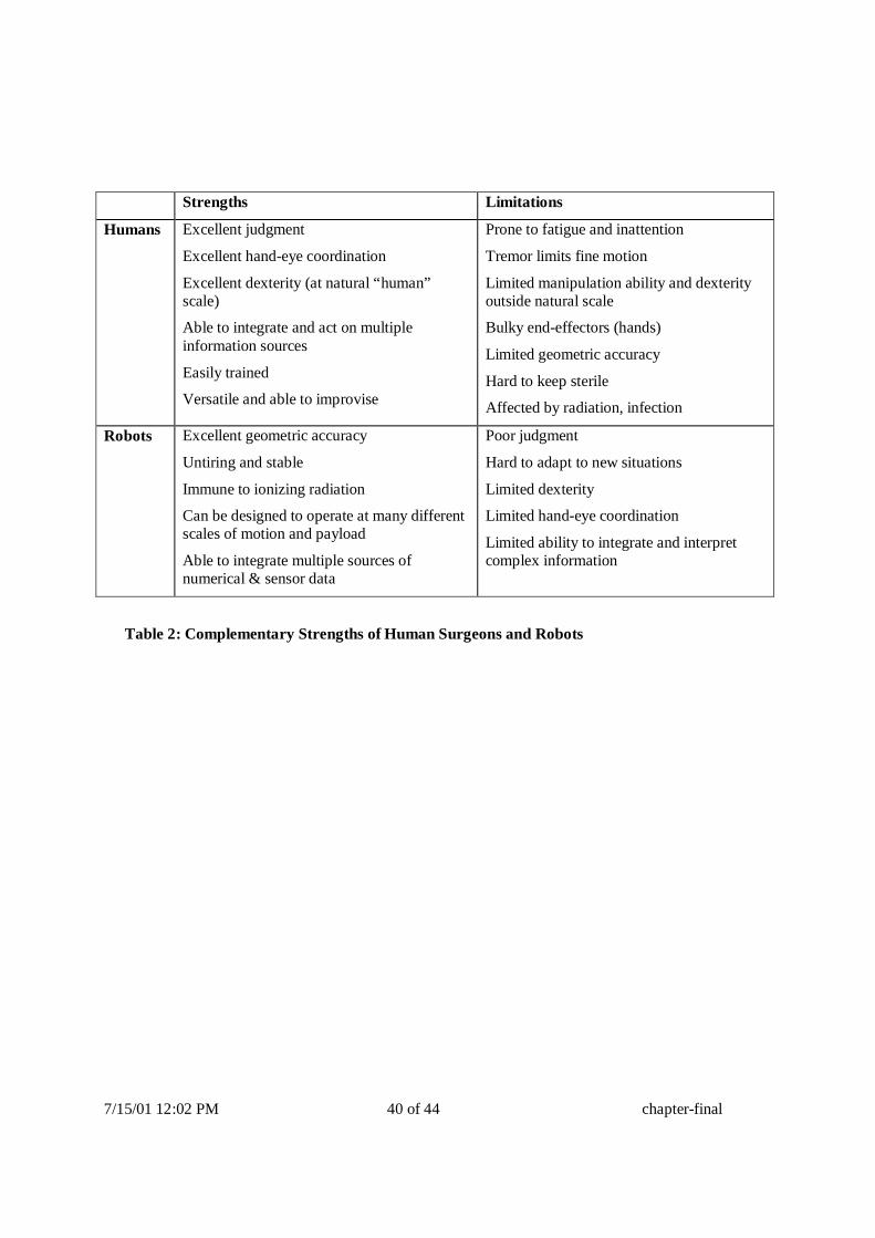
7/15/01 12:02 PM 40 of 44 chapter-final
Strengths L imitations
Humans Excellent judgment
Excellent hand-eye coordination
Excellent dexterity (at natural “ human” scale)
Able to integrate and act on multiple information sources
Easily trained
Versatile and able to improvise
Prone to fatigue and inattention
Tremor limits fine motion
Limited manipulation ability and dexterity outside natural scale
Bulky end-effectors (hands)
Limited geometric accuracy
Hard to keep sterile
Affected by radiation, infection
Robots Excellent geometric accuracy
Untiring and stable
Immune to ionizing radiation
Can be designed to operate at many different scales of motion and payload
Able to integrate multiple sources of numerical & sensor data
Poor judgment
Hard to adapt to new situations
Limited dexterity
Limited hand-eye coordination
Limited ability to integrate and interpret complex information
Table 2: Complementary Strengths of Human Surgeons and Robots

7/15/01 12:02 PM 41 of 44 chapter-final
Input: two data sets to be matched, image acquisition parameters
Process each data set separately to correct for geometric and intensity distortion and to reduce noise.
While there is dissimilarity and there is improvement do
Extract features or regions of interest from both images
Pair features from each data set
Formulate a similarity measure based on pairing
Find the transformation T that most reduces the dissimilarity
Transform one of the data sets by T
Output: transformation T
Table 4: Basic Steps of a Registration Algor ithm

7/15/01 12:02 PM 42 of 44 chapter-final
FIGURE CAPTIONS
Figure 1: Top: ROBODOC system for orthopaedic replacement surgery (photos by author). Bottom: Early version ROBODOC planning screen (left) and comparative cross sections showing conventionally broached (upper right) and robotically machined (lower left) cadaver femurs [1, 156, 157].
Figure 2: A CIS navigation system in action. The surgeon (left) is performing a brain tumor biopsy with the help of a navigation system. He is holding pointer with light-emitting diodes whose position and orientation is precisely determined in real time by a stereo tracking camera (up). The computer display (center) shows the preoperative MRI and the current position of the pointer. The image shows three orthogonal cross-sections and a three-dimensional reconstruction of the MRI data. The cross hair in each view shows the position of the pointer. The surgeon moves the pointer towards the desired position by watching the pointer location move on the screen as he moves the pointer.
Figure 3: The architecture of CIS systems: elements and interfaces
Figure 4: Major information flow in CIS systems
Figure 5: Volumetric rendering by ray casting (adapted from [9])
Figure 6:: Principle of the marching cubes algorithm: indexes for the marching cube (left) and coding scheme (right). (Reproduced with permission from [10]).
Figure 8: Two robotic assistants for laparoscopic surgery. The AESOP® system (left) is a widely deployed commercial system for manipulating a laparoscopic camera. The robot combines active joints with a 2 degree-of-freedom wrist to achieve 4 controlled motions of the endoscope while preventing lateral forces from being exerted at the entry point into the patient’s body. The experimental IBM/JHU LARS system used a 5 bar linkage to decouple rotational and translational motions at the entry point. Both approaches have been used in a number of experimental and clinically deployed surgical robots. (AESOP photo courtesy Computer Motion, Inc.)
Figure 9: Robot system for transurethral prostate surgery [25]. This system used goniometer arcs to provide conical motions about an apex point remote from the mechanism. (Photo courtesy Brian Davies).

7/15/01 12:02 PM 43 of 44 chapter-final
Figure 10: RCM robot with radiolucent PAKY end-effector used in percutaneous kidney stone removal [127, 158-162]. (Photo courtesy Dan Stoianovici)
Figure 12: Robotic system for diagnostic ultrasound [148]. (Photo courtesy S. Salcudean)
Figure 11: RCM robot with radiolucent CT-compatible needle driver [42, 44, 45]
Figure 15: MRI-compatible robot for breast biopsy [120]. Photo courtesy Harald Fischer.
Figure 16: Robot system for use in open-magnet MRI system [117].
Figure 17: Typical screen display of a CIS navigation system in action. The top left, right, and bottom windows show orthogonal cross-sectional views of the MRI data set. The cross hair in each shows the position of the tool tip at the center of the tumor. The bottom right window shows the spatial view, with the tool in yellow. (Photo courtesy of BrainLab).
Figure 18: : Screen display of a fluoroscopy-based navigation system during intramedullary nail distal locking. The windows show AP and lateral fluoroscopic X-ray images with the tool (solid green line) and its extension (dotted yellow line). The goal is to align the tool with the nail’s hole axis [59, 61](Photo Courtesy of L.P. Nolte).
Figure 19: Typical screen display of a CIS navigation system for endoscopic surgery. The left windows show orthogonal cross-sectional views of the CT data set and the endoscope image. The green line shows the position of the endoscope. The photograph on the right shows the endoscope and the tracking plate (Reproduced from [98]).
Figure 20: Augmented reality CIS system for brain tumor surgery. The tumor image (green) and brain structure (blue) are projected directly on the patient’s skull (Photo Courtesy of Ron Kikinis)
Figure 21: Virtual endoscopy: three-dimensional reconstruction of structure to be viewed (left) and view from the inside fly-through. (Reproduced from [98]).

7/15/01 12:02 PM 44 of 44 chapter-final
Figure 22: Information flow in a typical orthopaedic robotic system (in this case, the ISS ROBODOC system).
Figure 23: Early percutaneous therapy experiments at JHU using the LARS robot [110, 111].
Figure 21: Cooperative guiding using the LARS for neuroendoscopy experiment [54, 140-142]
Figure 22: Microsurgical Augmentation Experiments with the Johns Hopkins Steady-Hand robot [163]. Shows the current generation of the robot being used to evaluate robotically assisted stapedotomy. The current generation comprises an RCM linkage [164], a custom end-effector assembly [21, 165, 166], and off-the-shelf components. (Photo courtesy Dan Rothbaum, MD).
Figure 23: Comparative performance of human tremor and drift without a robot and with steady-hand manipulation augmentation[167]
Figure 24: Dexterous RCM end-effector for ultrasound and similar applications [116] mounted on an Integrated Surgical Systems Neuromate Robot. (Photo Courtesy Randy Goldberg)
Figure 25: Telesurgical augmentation system: In this “ telepresence” system the surgeon sits at a control console (left foreground) and manipulates a pair of “ master” robot arms while “ slave” robots (left background and right) mimic his motions inside the patient’s body [122]. (Photos courtesy Intuitive Surgical Systems).