Computer Graphics (CS 543) 11 (Part Image...
56
Computer Graphics (CS 543) Lecture 11 (Part 2): Image Manipulation Prof Emmanuel Agu Computer Science Dept. Worcester Polytechnic Institute (WPI)
Transcript of Computer Graphics (CS 543) 11 (Part Image...

Computer Graphics (CS 543) Lecture 11 (Part 2): Image Manipulation
Prof Emmanuel Agu
Computer Science Dept.Worcester Polytechnic Institute (WPI)

Image Processing
Graphics concerned with creating artificial scenes from geometry and shading descriptions
Image processing Input is an image Output is a modified version of input image
Image processing operations include altering images, remove noise, super‐impose images

Image Processing Example: Sobel Filter
Original Image Sobel Filter

Image Processing
Image processing the output of graphics rendering is called post‐processing
To post‐process using GPU, rendered output usually written to offscreen buffer (e.g. color image, z‐depth buffer, etc)
Image in offscreen buffer treated as texture, mapped to screen‐filling quadrilateral
Fragment shader invoked on each element of texture Performs calculation, outputs color to pixel in color buffer
Output image may be Displayed, saved as a texture, output to a file

Image Manipulation Basics
Note: Since S and T range from 0 to 1- Image center is at vec2(0.5, 0.5)

Vertex Shader
Most image processing in fragment shader Vertex shader just sets texture coordinates
out vec2 vST;
Void main( ){
vST = aTexCoord0.st;gl_Position = uModelViewProjectionMatrix * aVertex;
}

Luminance
Luminance of a color is its overall brightness Given a color in R G B, Compute it luminance by multiplying by a set of weights
(0.2125, 0.7154, 0.0721). i.e.
Luminance = R * 0.2125 + G * 0.7154 + B * 0.0721
Note that the weights sum to 1

Code (Fragment Shader) for Luminanceconst vec3 W = vec3(0.2125, 0.7154, 0.0721);vec3 irgb = texture( uImageUnit, vST).rgb;float luminance = dot(irgb, W);
fFragColor = vec4( luminance, luminance,luminance, 1.);
Insert figure 11.2

Image Negative
Another example

Image Filtering
A filter convolves (weighted addition?) a pixel with its neighbors Different algorithms have different filter sizes and values
Original Image
Sobel Filter
applied
121000121
Sobel Filter
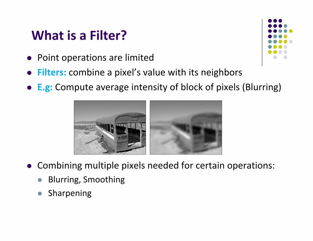
What is a Filter? Point operations are limited Filters: combine a pixel’s value with its neighbors E.g: Compute average intensity of block of pixels (Blurring)
Combining multiple pixels needed for certain operations: Blurring, Smoothing Sharpening

Definition: Spatial Filter

Example: Mean of 3x3 Neighborhood

Smoothing an Image by Averaging
Replace each pixel by average of neighboring pixels For 3x3 neighborhood:

Smoothing an Image by Averaging
Filter applies a function over small pixel neighborhood Filter size (size of neighborhood): 3x3, 5x5, 7x7, …,21x21,.. Filter shape: not necessarily square, can be rectangle, circle… Filters function: can be linear of nonlinear

Mean Filters: Effect of Filter Size

Integer Coefficient

Filters
Filters are usually square matrix and odd. E.g. 3x3 or 5x5
Example of a 5x5 image blur filter
Example of 3x3 image blur filter
1474141626164726412674162616414741
*2731
121242121
*161

Image Blurring
Sample images from 3x3 and 5x5 blur filters
Insert figure 11.5

Image Blurring Fragment Shader
Applying filter
Uniform sampler2D uImageUnit;in vec2 VST;out vec4 fFragColor;
void main( ){
ivec2 ires = textureSize( uImageUnit, 0);float ResS = float( ires.s );
121242121
*161

Image Blurring Fragment Shader (contd)float ResT = float( ires.t );vec3 irgb = texture(uImageUnit, VST ).rgb;
vec2 stp0 = vec2(1.ResS, 0. ); //texel offsetsvec2 st0p = vec2(0. , 1./ResT);vec2 stpp = vec2(1./ResS, 1./ResT);vec2 stpm = vec2(1./ResS, -1./ResT);
stpp
stpm
stp0
st0p
121242121
*161

Image Blurring Fragment Shader (contd)// 3x3 pixel colors nextvec3 i00 = texture( uImageUnit, vST ).rgb;vec3 im1m1 = texture( uImageUnit, vST-stpp ).rgb;vec3 ip1p1 = texture( uImageUnit, vST+stpp ).rgb;
vec3 im1p1 = texture( uImageUnit, vST-stpm ).rgb;vec3 ip1m1 = texture( uImageUnit, vST+stpm ).rgb;
vec3 im10 = texture( uImageUnit, vST-stp0 ).rgb;vec3 ip10 = texture( uImageUnit, vST+stp0 ).rgb;
vec3 i0m1 = texture( uImageUnit, vST-st0p ).rgb;vec3 i0p1 = texture( uImageUnit, vST+st0p ).rgb;
121242121
*161
stpp
stpm
stp0
st0p

Image Blurring Fragment Shader (contd)vec3 target = vec3(0., 0., 0.);target += 1.*(im1m1+ip1m1+ip1p1+im1p1);// apply blurtarget += 2.*(im10+ip10+i0m1+i0p1);target += 4.*(i00);
target /= 16.;
fFragColor = vec4( target, 1. );
121242121
*161

Types of Linear Filters
Box Gaussian Laplace

Edge Detection
Uses 2 filters: 1 vertical and 1 horizontal Vertical is actually horizontal rotated 90 degrees

Edge Detection
Algorithm: Compare 2 columns (or rows)
If difference is “large”, this is an edge If difference is “small”, not an edge
Comparison can be done in color or luminance
Insert figure 11.11

Edge Detection Fragment Shader

Embossing
Embossing is similar to edge detection Depending on edge angle (how sharp)
Replace color by luminance Highlight images differently depending on edge angles
Insert figure 11.12

Embossing

Toon Rendering for Non‐Photorealistic Effects
Toon Shader
Implement Toon shader based using Sobel filter Algorithm
Calculate luminance of each pixel Apply Sobel edge detection filter and get a magnitude If magnitude > threshold, color pixel black Else, quantize pixel’s color Output the colored pixel

Toon Fragment Shader (Some Code)… insert code for Sobel Filter
// Calculate magnitude, then draw edges or quantizefloat mag = length( vec2(h, v) );// how much change?
if( mag > uMagTo ) // if too much, use blackfFragColor = vec4( 0., 0., 0., 1.);
else{ // else quantize the colorrgb.rgb *= uQuantize; // multiply by number of quanta rgb.rgb += vec3( .5, .5, .5); // roundivec3 intrgb = ivec3( rgb.rgb ); // truncatergb.rgb = vec3( intrgb )/ Quantize; // calc. quantized colorfFragColor = vec4( rgb, 1.);
}
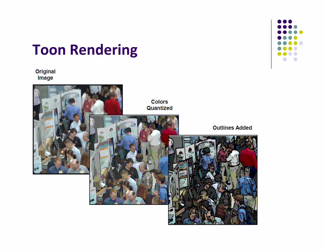
Toon Rendering

Image Flipping, Rotation and Warping
We can transform image (flip, rotate, warp) Basic idea: Look up a transformed pixel address instead of
the current one To flip an image upside down:
At pixel location st, look up the color at location s (1 – t) Fragment shader code:
vec2 st = vST;st.t = 1 - st.t;vec3 irgb = texture( uImageUnit, st ).rgb;fFragColor = vec4( irgb, 1);
Note: For horizontal flip, look up (1 – s) t instead of s t !!

Image Flipping, Rotation and Warping
Rotating an image 90 degrees counterclockwise: Look up (t, 1 – s) instead of s t
Image warping: we can use a function to select which pixel somewhere else in the image to look up
For example: apply function on both texel coordinates (s, t)
)*sin(* xtxx

Image Flipping, Rotation and Warping
)*sin(* xtxx
Insert figure 11.16

Image Flipping, Rotation and Warping
Fragment shader code to implement
const float PI = 3.14159265 uniform sampler2D uImageUnit; uniform float uT;in vec2 vST; out vec4 fFragColor;
void main( ){vec2 st = vST;vec2 xy = st;xy = 2. * xy – 1; // map to [-1,1] squarexy += uT * sin(PI*xy);st = (xy + 1.)/2.; // map back to [0,1] squarevec3 = irgb = texture(uImageUnit, st ).rgb;fFragColor = vec4( irgb, 1.); }
)*sin(* xtxx

Non‐Linear Image Warps
Original Twirl Ripple Spherical

Twirl Notation: Instead using texture colors at (x’,y’), use texture colors at
twirled (x,y) location Twirl?
Rotate image by angle α at center or anchor point (xc,yc) Increasingly rotate image as radial distance r from center
increases (up to rmax) Image unchanged outside radial distance rmax

Twirl Fragment Shader Codeconst float PI = 3.14159265uniform sampler2D uImageUnit;uniform float uD, uR;
in vec3 vST;out vec4 fFracColor;
void main( ){ivec2 ires = textureSize( uImageUnit, 0);float Res = float( ires.s ); // assume it’s a square texture image
vec2 st = vST;float Radius = Res * uR;vec2 xy = Res * st; // pixel coordinates from texture coords
vec2 dxy = xy – Res/2.; // twirl center is (Res/2, Res/2)float r = length( dxy );float beta = atan( dxy.y, dxy.x) + radians(uD) * (Radius – r)/Radius;

Twirl Fragment Shader Code (Contd)vec2 xy1 = xy;if(r <= Radius){
xy1 = Res/2. + r * vec2( cos(beta), sin(beta) );}st = xy1/Res; // restore coordinates
vec3 irgb = texture( uImageUnit, st ).rgb;fFragColor = vec4( irgb, 1. );
}
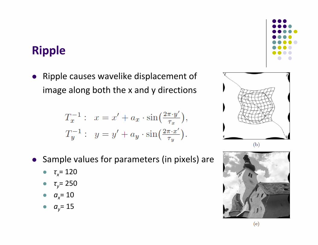
Ripple
Ripple causes wavelike displacement ofimage along both the x and y directions
Sample values for parameters (in pixels) are τx= 120 τy= 250 ax= 10 ay= 15

Spherical Transformation
Imitates viewing image through a lens placed over image Lens parameters: center (xc, yc ), lens radius rmax and refraction index ρ Sample values ρ = 1.8 and rmax = half image width

Image Warping
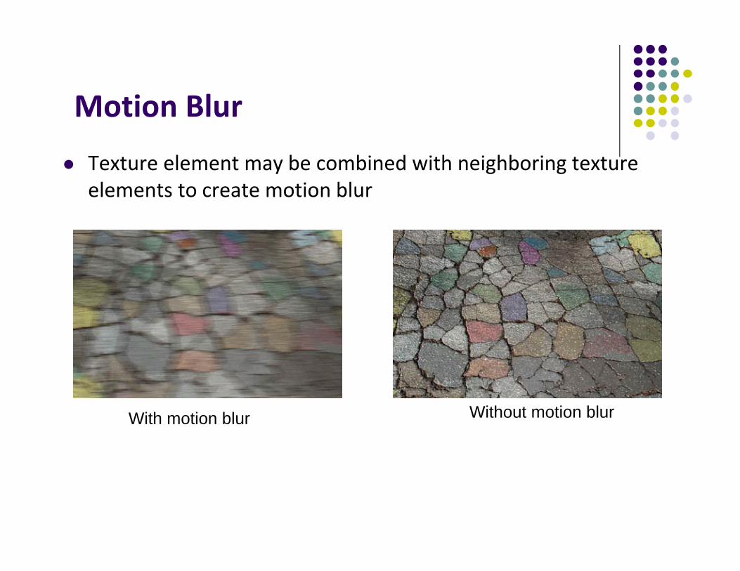
Motion Blur
Texture element may be combined with neighboring texture elements to create motion blur
With motion blur Without motion blur

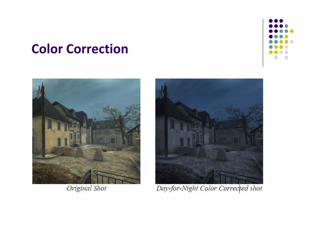
Color Correction
Color correction uses a function to convert colors in an image to some other color
Why color correct? Mimic appearance of a type of film Portray a particular mood Convert from one color space to another (e.g. RGB to CIE) Example of conversion from RGB to CIE’s XYZ color space
BGR
ZYX
950227.0119193.0019334.0072169.0715160.0212671.0180423.0357580.0412453.0

Color Correction
Color Correction

High Dynamic Range
Sun’s brightness is about 60,000 lumens Dark areas of earth has brightness of 0 lumens Basically, world around us has range of 0 – 60,000 lumens
(High Dynamic Range) However, monitor has ranges of colors between 0 – 255 (Low
Dynamic Range) New file formats have been created for HDR images (wider
ranges). (E.g. OpenEXR file format)
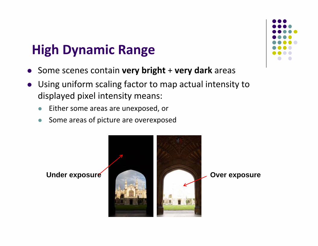
High Dynamic Range Some scenes contain very bright + very dark areas Using uniform scaling factor to map actual intensity to
displayed pixel intensity means: Either some areas are unexposed, or Some areas of picture are overexposed
Under exposure Over exposure

Tone Mapping
Technique for scaling intensities in real world images (e.g HDR images) to fit in displayable range
Try to capture feeling of real scene: non‐trivial Example: If coming out of dark tunnel, lights should seem
bright General idea: apply different scaling factors to diffferent
parts of the image

Tone Mapping

Depth of Field We can simulate a real camera In photographs, a range of pixels in focus Pixels outside this range are out of focus This effect is known as Depth of field

Motion Blur Motion blur caused by exposing film to moving objects Motion blur: Blurring of samples taken over time (temporal) Makes fast moving scenes appear less jerky 30 fps + motion blur better than 60 fps + no motion blur

Motion Blur Basic idea is to average series of images over time Move object to set of positions occupied in a frame, blend
resulting images together Can blur moving average of frames. E.g blur 8 images Velocity buffer: blur in screen space using velocity of objects

References Mike Bailey and Steve Cunningham, Graphics Shaders (second
edition) Wilhelm Burger and Mark Burge, Digital Image Processing: An
Algorithmic Introduction using Java, Springer Verlag Publishers OpenGL 4.0 Shading Language Cookbook, David Wolff Real Time Rendering (3rd edition), Akenine‐Moller, Haines and
Hoffman Suman Nadella, CS 563 slides, Spring 2005