Computer Architecture Review - Yajinyajin.org/os2019fall/ppt/01_computerarchitecture.pdf · Decades...
55
Computer Architecture Review Operating Systems Credits: Slides are from Henri Casanova@Hawaii.
Transcript of Computer Architecture Review - Yajinyajin.org/os2019fall/ppt/01_computerarchitecture.pdf · Decades...

Computer
Architecture
Review
Operating Systems
Credits: Slides are from Henri Casanova@Hawaii.

ENIAC (1946)
◼ Electronic Numerical
Integrator and Calculator
Considered by most to be the
first electronic computer
Vacuum tubes, punchcards
50,000+ times slower than
my laptop
100ft long
◼ each register: 20ft
Programming with wires

Von-Neumann
◼ In 1944, John von Neumann joined ENIAC
◼ He wrote a memo about computer
architecture, formalizing ENIAC ideas
Eckert and Mauchly have pretty much been
forgotten (they were in the trenches)
◼ These ideas became the Von Neumann
architecture model
A processor that performs operations and
controls all that happens
A memory that contains code and data
I/O of some kind

Von-Neumann Model
◼ Amazingly, it’s still possible to think of the computer this
way at a conceptual level (model from ~70 years ago!!!)
◼ A computer today has
some differences
CPU Memory
I/O
System

Von-Neumann Model
◼ Amazingly, it’s still possible to think of the computer this
way at a conceptual level (model from ~70 years ago!!!)
◼ A computer today has
some differences
CPU Memory
I/O
System
Memory Bus

Data Stored in Memory
◼ All “information” in the computer is in binary form
Since Claude Shannon’s M.S. thesis in the 30’s
0: zero voltage, 1: positive voltage (e.g., 5V)
bit: the smallest unit of information (0 or 1)
◼ The basic unit of memory is a byte
1 Byte = 8 bits, e.g., “0101 1101”
◼ Each byte in memory is labeled by a unique address
◼ All addresses in the machine have the same number of bits
e.g., 64-bit addresses on ARM64
◼ The processor has instructions that say “Read the byte at address X and give me its value” and “Write some value into the byte at address X”
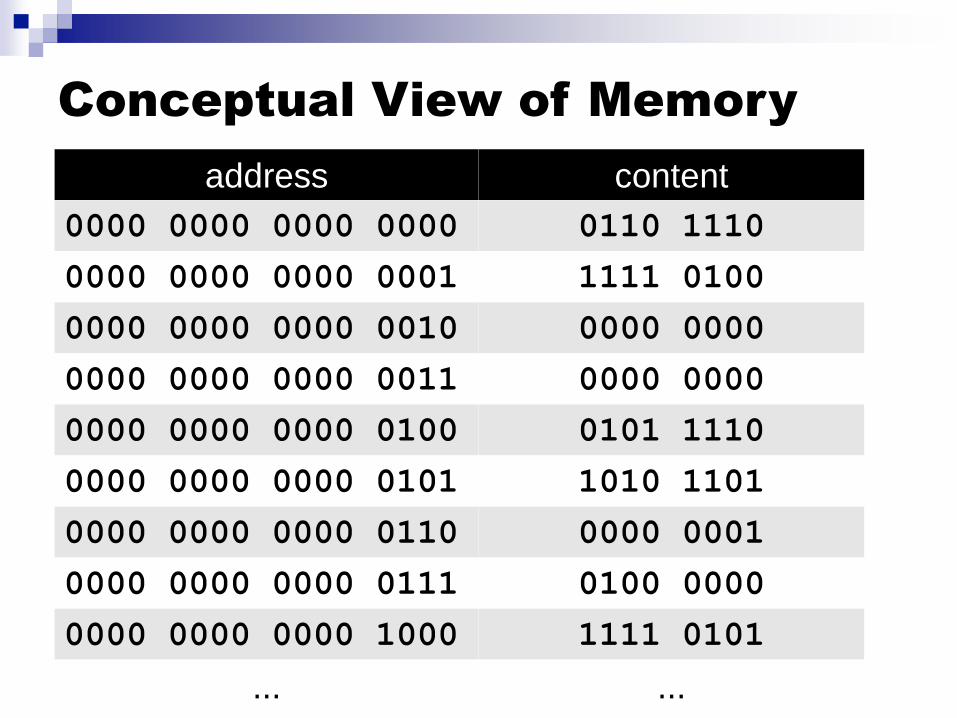
Conceptual View of Memory
address content
0000 0000 0000 0000 0110 1110
0000 0000 0000 0001 1111 0100
0000 0000 0000 0010 0000 0000
0000 0000 0000 0011 0000 0000
0000 0000 0000 0100 0101 1110
0000 0000 0000 0101 1010 1101
0000 0000 0000 0110 0000 0001
0000 0000 0000 0111 0100 0000
0000 0000 0000 1000 1111 0101
... ...
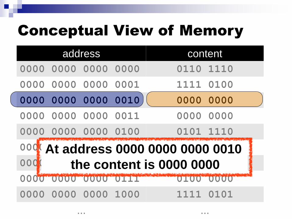
At address 0000 0000 0000 0010
the content is 0000 0000

Conceptual View of Memory
address content
0000 0000 0000 0000 0110 1110
0000 0000 0000 0001 1111 0100
0000 0000 0000 0010 0000 0000
0000 0000 0000 0011 0000 0000
0000 0000 0000 0100 0101 1110
0000 0000 0000 0101 1010 1101
0000 0000 0000 0110 0000 0001
0000 0000 0000 0111 0100 0000
0000 0000 0000 1000 1111 0101
... ...
At address 0000 0000 0000 0100
the content is 0101 1110

Both Code and Data in Memory
Memory
0010 00010000 1110
1111 00001000 0000
... ...
Address Value
0000 1100 0110 1011
0000 1101 1111 0010
0101 11111111 0010
... ...
Code
Data
◼ Once a program is loaded in memory, its address space contains both code and data
◼ To the CPU those are not really different, but the programmer knows which bytes are data an which are code
Always conveniently hidden from you if you’ve never written assembly
But we’ll have to keep code/data straight in these lecture notes
Example Address Space

We need a CPU
◼ So now we have a memory in which we can store/retrieve bytes at precise location
◼ These bytes presumably have some useful meaning to us e.g., integers, ASCII codes of characters, floating points
numbers, RGB values
e.g., instructions that specify what to do with the data; when you buy a processor, the vendor defines the instruction set (e.g., instruction “0010 1101” means “increment some useful counter”)
◼ The CPU is the piece of hardware that modifies the content of memory In fact, one can really think of the CPU as a device that takes
use from one memory state (i.e, all the stored content) to another memory state (some new, desired stored content)

What’s in the CPU?
Memory
I/O
System
CPU

What’s in the CPU?
Memory
I/O
System
Control
UnitALU
Program counter register
register
register
current instruction

What’s in the CPU?
Control
UnitALU
Program counter register
register
register
Registers: the “variables” that hardware instructions work with
Data can be loaded from memory into a register
Data can be stored from a register back into memory
Operands and results of computations are in registers
Accessing a register is really fast
There is a limited number of registers
current instruction
What’s in the CPU?
Control
UnitALU
Program counter register
register
register
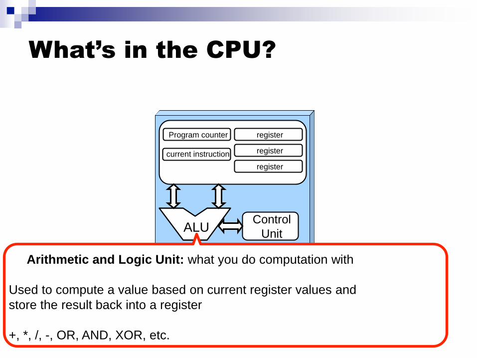
Arithmetic and Logic Unit: what you do computation with
Used to compute a value based on current register values and
store the result back into a register
+, *, /, -, OR, AND, XOR, etc.
current instruction

What’s in the CPU?
Control
UnitALU
Program counter register
register
register
Program Counter: Points to the next instruction
Special register that contains the address in memory of the next instruction
that should be executed
(gets incremented after each instruction, or can be set to whatever value
whenever there is a change of control flow)
current instruction

What’s in the CPU?
Control
UnitALU
Program counter register
register
register
Current Instruction: Holds the instruction that’s currently being executed
current instruction

What’s in the CPU?
Control
UnitALU
Program counter register
register
register
Control Unit: Decodes instructions and make them happen
Logic hardware that decodes instructions (i.e., based on their bits) and sends
the appropriate (electrical) signals to hardware components in the CPU
current instruction

The CPU in its “Glory”

Fetch-Decode-Execute Cycle
◼ The Fetch-Decode-Execute cycle
The control unit fetches the next program instruction from memory
◼ Using the program counter to figure out where that instruction is located in the memory
The instruction is decoded and signals are send to hardware components
◼ e.g., is the instruction loading something from memory? is it adding two register values together?
Operands are fetched from memory and put in registers, if needed
The ALU executes computation, if any, and store results in the registers
Register values are stored back to memory, if needed
Repeat
◼ Computers today implement MANY variations on this model
◼ But one can still program with the above model in mind
but certainly without (fully) understanding performance issues

Fetch-Decode-Execute
Memory
0010 00010000 1110
1111 00001000 0000
... ...
Address Value
0000 1100 0110 1011
0000 1101 1111 0010
0101 11111111 0010
... ...
Control
UnitALU
register
register
register
program counter
current instruction

Fetch-Decode-Execute
Memory
0010 00010000 1110
1111 00001000 0000
... ...
Address Value
0000 1100 0110 1011
0000 1101 1111 0010
0101 11111111 0010
... ...
Control
UnitALU
0000 1100register
register
register
program counter
current instruction
Somehow, the program counter is
initialized to some content, which is an
address (we’ll see how that happens
much later)

Fetch-Decode-Execute
Memory
0010 00010000 1110
1111 00001000 0000
... ...
Address Value
0000 1100 0110 1011
0000 1101 1111 0010
0101 11111111 0010
... ...
Control
UnitALU
0000 1100register
register
register
program counter
Fetch the content (instruction) at
address 0000 1100, which is “0110
1011”, and store it in the “current
instruction” register
current instruction
0110 1011

Fetch-Decode-Execute
Memory
0010 00010000 1110
1111 00001000 0000
... ...
Address Value
0000 1100 0110 1011
0000 1101 1111 0010
0101 11111111 0010
... ...
Control
UnitALU
0000 1101register
register
register
program counter
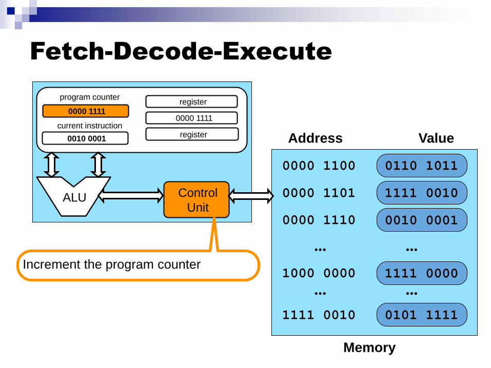
Increment the program counter
current instruction
0110 1011

Fetch-Decode-Execute
Memory
0010 00010000 1110
1111 00001000 0000
... ...
Address Value
0000 1100 0110 1011
0000 1101 1111 0010
0101 11111111 0010
... ...
Control
UnitALU
0000 1101register
register
register
program counter
Decode instruction “0110 1011”. Say it
means: “Load the value at address
1000 0000 and store it in the second
register”
current instruction
0110 1011

Fetch-Decode-Execute
Memory
0010 00010000 1110
1111 00001000 0000
... ...
Address Value
0000 1100 0110 1011
0000 1101 1111 0010
0101 11111111 0010
... ...
Control
UnitALU
0000 1101register
1111 0000
register
program counter
Send signals to all hardware
components to execute the instruction:
load the value at address 1000 0000,
which is “1111 0000” and store it in the
second register
current instruction
0110 1011

Fetch-Decode-Execute
Memory
0010 00010000 1110
1000 0000
... ...
Address Value
0000 1100 0110 1011
0000 1101 1111 0010
0101 11111111 0010
... ...
Control
UnitALU
0000 1101register
1111 0000
register
program counter
Fetch the content (instruction) at
address 0000 1101, which is “1111
0010”, and store it in the “current
instruction” register
current instruction
1111 0010
1111 0000

Fetch-Decode-Execute
Memory
0010 00010000 1110
1111 00001000 0000
... ...
Address Value
0000 1100 0110 1011
0000 1101 1111 0010
0101 11111111 0010
... ...
Control
UnitALU
0000 1110register
register
program counter
Increment the program counter
current instruction
1111 0010
1111 0000

Fetch-Decode-Execute
Memory
0010 00010000 1110
1111 00001000 0000
... ...
Address Value
0000 1100 0110 1011
0000 1101 1111 0010
0101 11111111 0010
... ...
Control
UnitALU
0000 1110register
register
program counter
current instruction
1111 0010
1111 0000
Decode instruction “1111 0010”. Say it
means: “Do a logical NOT on the
second register”

Fetch-Decode-Execute
Memory
0010 00010000 1110
1111 00001000 0000
... ...
Address Value
0000 1100 0110 1011
0000 1101 1111 0010
0101 11111111 0010
... ...
Control
UnitALU
0000 1110register
register
program counter
current instruction
1111 0010
0000 1111
Send signals to all hardware
components to execute the instruction:
do a logical NOT on the second
register

Fetch-Decode-Execute
Memory
0010 00010000 1110
1000 0000
... ...
Address Value
0000 1100 0110 1011
0000 1101
0101 11111111 0010
... ...
Control
UnitALU
0000 1110register
0000 1111
register
program counter
Fetch the content (instruction) at
address 0000 1110, which is “0010
0001”, and store it in the “current
instruction” register
current instruction
0010 0001
1111 0000
1111 0010
Fetch-Decode-Execute
Memory
0000 1110
1000 0000
... ...
Address Value
0000 1100 0110 1011
0000 1101
0101 11111111 0010
... ...
Control
UnitALU
0000 1111register
0000 1111
register
program counter
current instruction
0010 0001
1111 0000
1111 0010
Increment the program counter
0010 0001
Fetch-Decode-Execute
Memory
0000 1110
1000 0000
... ...
Address Value
0000 1100 0110 1011
0000 1101
0101 11111111 0010
... ...
Control
UnitALU
0000 1111register
0000 1111
register
program counter
current instruction
0010 0001
1111 0000
1111 0010
0010 0001
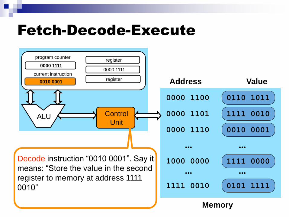
Decode instruction “0010 0001”. Say it
means: “Store the value in the second
register to memory at address 1111
0010”

Fetch-Decode-Execute
Memory
0000 1110
1000 0000
... ...
Address Value
0000 1100 0110 1011
0000 1101
0000 11111111 0010
... ...
Control
UnitALU
0000 1111register
0000 1111
register
program counter
current instruction
0010 0001
1111 0000
1111 0010
0010 0001
Send signals to all hardware
components to execute the instruction:
store the value in the second register,
which is 0000 1111, to memory at
address 1111 0010

Fetch-Decode-Execute
◼ This is only a simplified view of the way things work
◼ The “control unit” is not a single thing Control and data paths are implemented by several complex
hardware components
◼ There are multiple ALUs, there are caches, there are multiple CPUs in fact (“cores”)
◼ Execution is pipelined: e.g., while one instruction is fetched, another is executed
◼ Decades of computer architecture research have gone into improving performance, thus often leading to staggering hardware complexity Doing smart things in hardware requires more logic gates and
wires, thus increasing processor cost
◼ But conceptually, fetch-decode-execute is it

In-Class Exercise◼ With the following (totally made up and strange, but small)
instruction set definition and with this machine state, what is the
new memory state after execution completes?
0010 00010000 1101
1111 00001000 0000
... ...
0000 1100 1111 0010
0101 11111000 0001Control
UnitALU
program counter
1000 0000
code operation
1111 0000 Increment the register
1111 0010 Decrement the register
0101 1111 Save register to address NOT(register)
1111 0010
register

◼ Fetch the instruction: “1111 0000”
◼ Execute it: increment register to value “1111 0011”
◼ Fetch the next instruction: “1111 0001”
◼ Execute it: save value “1111 0011” to address “0000 1100”
0010 00010000 1101
1111 00001000 0000
... ...
0000 1100 1111 0010
0101 11111000 0001Control
UnitALU
program counter
1000 0001
code operation
1111 0000 Increment the register
1111 0010 Decrement the register
0101 1111 Save register to address NOT(register)
1111 0011
register

◼ Fetch the instruction: “1111 0000”
◼ Execute it: increment register to value “1111 0011”
◼ Fetch the next instruction: “0101 1111”
◼ Execute it: save value “0101 1111” to address “0000 1100”
0010 00010000 1101
1111 00001000 0000
... ...
0000 1100 1111 0011
0101 11111000 0001Control
UnitALU
program counter
1000 0001
code operation
1111 0000 Increment the register
1111 0010 Decrement the register
0101 1111 Save register to address NOT(register)
1111 0011
register

Direct Memory Access
◼ DMA is used in all modern computers
◼ It’s a way for the CPU to let memory-I/O operations (data transfers)
occur independently
◼ Say you want to write 1GiB from memory to some external device like
a disk, network card, graphics card, etc.
◼ The CPU would be busy during this slow transfer
Load from memory into registers, write from registers to disk, continuously
◼ Instead, a convenient piece of hardware called the DMA controller can
make data transfer operations independently of the CPU
◼ The CPU simply “tells” the DMA controller to initiate a transfer
Which is done by writing to some registers of the DMA controller
◼ When the transfer completes, the DMA controller tells the CPU “it’s
done” (by generating an interrupt)
More on interrupts later
◼ In the meantime, the CPU can do useful work, e.g., run programs

DMA is not completely free
◼ To perform data transfers the DMA controller uses the memory bus
◼ In the meantime, the code executed by the CPU likely also uses the memory bus
◼ Therefore, the two can interfere
◼ There are several modes in which this interference can be managed DMA has priority
CPU has priority
◼ But in general, using DMA leads to much better performance anyway

Coping with Slow RAM
◼ Everybody would like to have a computer with a very large and very fast memory
◼ Unfortunately, technology (affordably) allows for either slow and large or fast and small
◼ We need large main memories for large programs and data
◼ Therefore, from the CPU’s perspective, main memory is slooooooow
◼ What we do: we play a trick to provide the illusion of a fast memory
◼ This trick is called the memory hierarchy

The Memory Hierarchy
fast slow
small large
◼ Real-world has multiple levels of caches (L1, L2, L3)
◼ Chunks of data are brought in from far-away memory and are
copied and kept around in nearby memory
Yes, the same data exists in multiple levels of memory at once
◼ Miss: when a data item is not found in a level (e.g., L1 cache miss)
◼ Hit: when a data item is found in a level (e.g., L2 cache hit)

Caching
◼ Whenever your program accesses a byte of memory what
happens is:
That byte’s value is brought from slooooow memory into the fast
cache
byte values around the byte you accesses are also brought from
slooooow memory into the fast cache
◼ Analogy:
You need a book from the library
You go there and find the book on the many shelves of the library
You bring back home all books on that shelf and put them on your
own bookshelf in your house
Next time you need that book or one of the books “around it”, it will
take you no time at all to get it
◼ Presumably all books on a shelf at the library are about the same topic, so
you’ll need the books around the book you wanted in the first place

Why Does it Work?
◼ Temporal Locality: a program tends to reference
addresses it has recently referenced
The first access, you pay the cost of going to far-
away/slow memory to fetch the counter’s content
Subsequent accesses are fast
This is the “I need that book again” analogy
◼ Spatial Locality: a program tends to reference
addresses next to addresses it has recently referenced
The first access of array element i may be costly
But the first access of array element i+1 is fast (in the
chunk)
This is the “I need another book on that same shelf”
analogy

Memory Tech. and Management
◼ Main memory and disk are managed by the OS
◼ When dealing with a “slow” level, it pays off more to try being “clever” (i.e., spending more time trying to make good decisions)
Part of why OSes are doing complicated things, as opposed to hardware which tries to do simple things fast
and others

SMP Systems
◼ Symmetric multi processors
Issue: Cache coherency
(see textbook)

Moore’s Law
◼ In 1965, Gordon Moore (co-founder
of Intel) predicted that transistor
density of semiconductor chips
would double roughly every 24 months
(often “misquoted” as 18 months)
He was right
But, the law was often wrongly interpreted as:
“Computers get twice as fast every 2 years”
This wrong interpretation was true for a while, but no
longer...

Moore’s Law
This did not
happen!!
Multi-core Chips
◼ Constructors cannot increase clock rate
further
Power/heat issues
◼ They bring you multi-core processors
Multiple “low” clock rate processors on a chip
◼ It’s really a solution to a problem, not a cool
new advance
Even though there are many cool/interesting
things about multicore processors
◼ Most users/programmers would rather have
a 100GHz core than 50 2GHz cores

Multi-Core Systems
Figure 1.7 from the book More realistic picture
registers
s
registers
s
L1 cache L1 cache
memory
L2 cache

Multi-Proc Multi-Core Systems
registers
s
registers
s
L1 cache L1 cache
L2 cache
registers
s
registers
s
L1 cache L1 cache
L2 cache
memory

Takeaway• Each byte in memory is labeled by a unique address• CPU architecture• The Fetch-Decode-Execute cycle
Memory
I/O
System
Control
UnitALU
Program counter register
register
register
current instruction

Conclusion
◼ If you want to know more
Take a computer architecture
course
Classic Textbook by Patterson
and Hennessy
◼ Reading assignment:
Sections 1.2 and 1.3