Computer Architecture Lecture 32 Fasih ur Rehman.
33
Computer Architecture Lecture 32 Fasih ur Rehman
-
Upload
lewis-gibbs -
Category
Documents
-
view
224 -
download
3
Transcript of Computer Architecture Lecture 32 Fasih ur Rehman.

Computer Architecture
Lecture 32Fasih ur Rehman

Last Class
• Revision– Basic Concepts– Components of a Computer– Performance– Addresses and Addressing Modes– Input and Output organization– Interrupts– DMA and I/O interface Circuits– Bus Organization– Basic Processing Unit– Control Unit Design

Today’s Agenda
• Revision– Arithmetic Unit Design– Floating point Unit– Memories– Data Communication and Error Control

Signed Numbers
• Representation Methods– Signed Magnitude– 1’s Complement– 2’s Complement

Binary Addition/Subtraction Logic Circuit
4 – bit Carry Lookahead Adder

Array Multiplication (Unsigned)

Sequential Multipliers

Booth Algorithm
• Thus recoding can be done using following table called Booth Recoding Table

Multiplier Bit Recoding
Fast Multiplication
• Bit pair recoding reduces summands by a factor of 2
• Summands are reduced by carry – save addition• Final product can be generated by using carry
lookahead adder

Longhand Division Steps
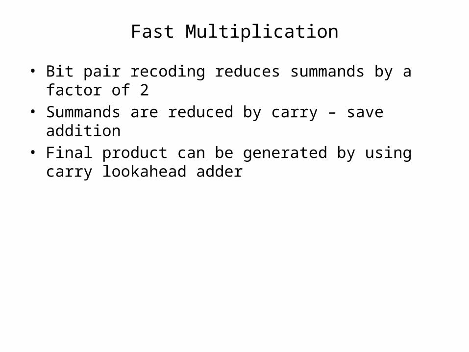
• Position the divisor appropriately with respect to the dividend and performs a subtraction.
• If the remainder is zero or positive, a quotient bit of 1 is determined, the remainder is extended by another bit of the dividend, the divisor is repositioned, and another subtraction is performed.
• If the remainder is negative, a quotient bit of 0 is determined, the dividend is restored by adding back the divisor, and the divisor is repositioned for another subtraction.
Circuit Arrangement
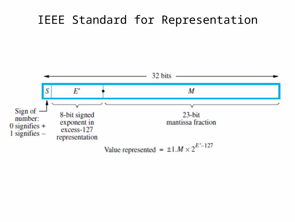
IEEE Standard for Representation

Addition / Subtraction Rules
• Choose the number with the smaller exponent and shift its mantissa right a number of steps equal to the difference in exponents.
• Set the exponent of the result equal to the larger exponent.
• Perform addition/subtraction on the mantissas and determine the sign of the result.
• Normalize the resulting value, if necessary.• 3.1415 x 10⁸ + 1.19 x 106 = 3.1415 x 10⁸ + 0.0119 x 108 =
3.1534 x 10⁸
Multiplication Rules
• Add the exponents and subtract 127 to maintain the excess-127 representation.
• Multiply the mantissas and determine the sign of the result.
• Normalize the resulting value, if necessary.

Division Rules
• Subtract the exponents and add 127 to maintain the excess-127 representation.
• Divide the mantissas and determine the sign of the result.
• Normalize the resulting value, if necessary.
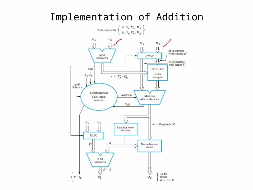
Implementation of Addition

Random Access Memory
• Random access memory (RAM), any location can be accessed with comparable access time (e.g. CD vs. tape drive)
• Processor usually runs much faster than main memory– Small memories fast, large memories slow– Use a cache memory to store data that is likely to be
used• Types of RAM
– Static RAM– Dynamic RAM
• SDRAM• SDRAM DDR

Memory Controller
• A memory controller is normally used to interface between DRAM and the processor. Dynamic RAMs have a slightly more complex interface as they multiplex signals in time to reduce pins
• SRAM interfaces are simpler and may not need a memory controller

Read Only Memories
• RAMs are volatile• We need some memory to be retained even if the
power is switched off.– For example, booting a computer
• So we need some arrangement or non – volatile memory to store some instructions that need to be executed at start up.
• Non – volatile memory is read in a same manner as the RAM and called Read only Memories– Special writing process is needed
• Types of ROMs
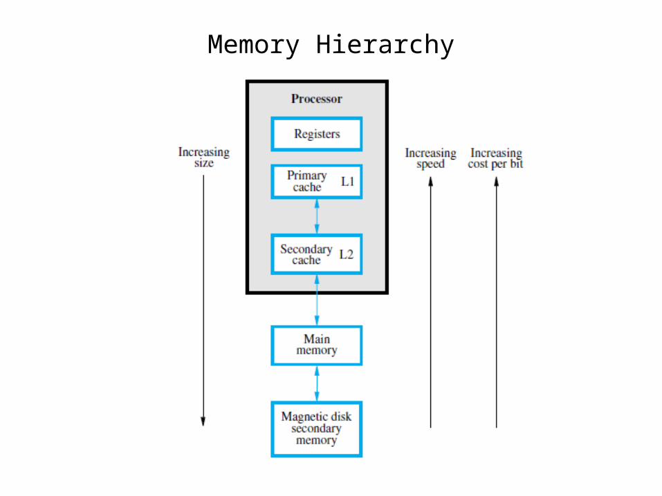
Memory Hierarchy

Cache Memories
• Processor runs at much faster speed than its main memory (MM)– Processor will then have to wait for a while data and
instruction are read from the memory– degrades the performance of the computer system– Speed of MM is bounded by certain constraints
• Cache memory uses principal of “Locality of Reference” which makes MM appear (to the processor) faster than it actually is.
• Cache Read/Write/Hit/Miss/Miss Penalty

Mapping Functions
• Three types of Mappings– Direct Mapping– Associative Mapping– Set Associative Mapping

Replacement Algorithms
• Direct mapped cache– Position of each block fixed, no replacement algorithm
needed• Associative and Set associative
– Need to decide which block to replace (keep ones likely to be used in cache)
– One strategy is least recently used (LRU) e.g. for a 4 block cache, use a 2-bit counter. Set =0 for block accessed, other blocks incremented. Block with count=3 replaced upon miss
– Another is random replacement (choose random block). Advantage is that it is easier to implement at high speed

Virtual Memory Organization

Address Translation
Address of the page table.
PTBR + virtual page number = Entry of the page in the page table.
Starting address of the page in the main memory.
Starting location of the page.
Virtual address = pagenumber + offset.

Translation Lookaside Buffer
• Associative or set associative scheme normally used
• Processor must keep TLB and page table information consistent

Computer Communication
• Data• Digital Vs. Analog• Codes
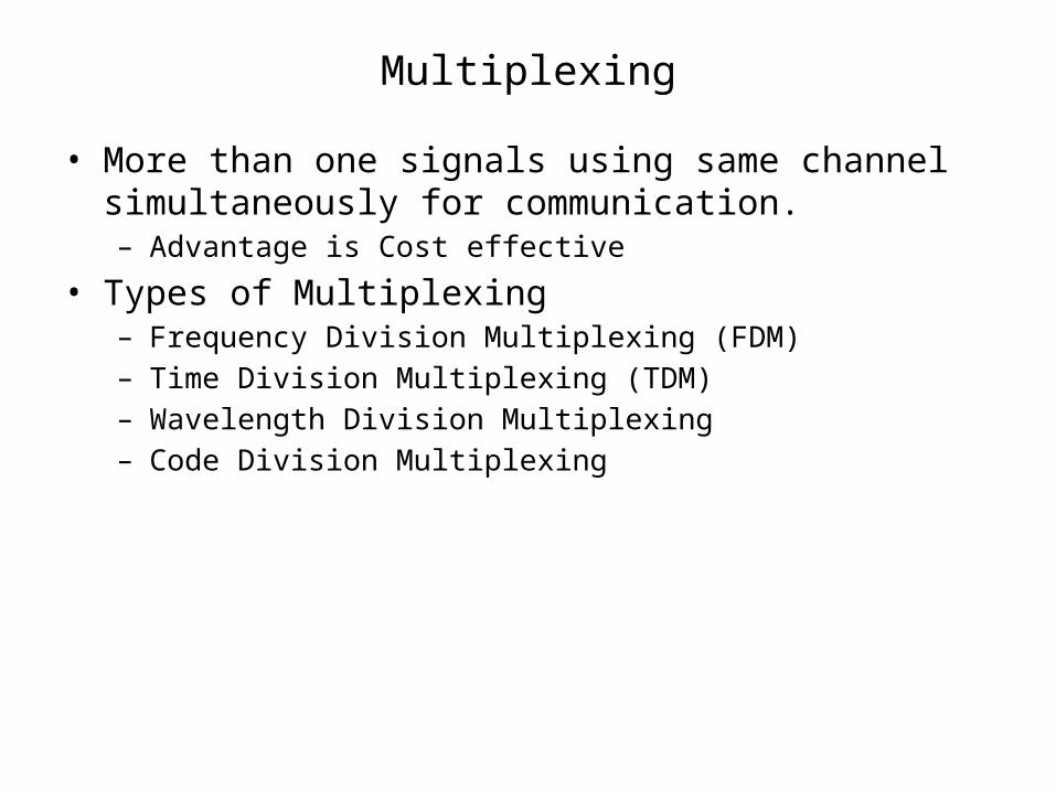
Multiplexing
• More than one signals using same channel simultaneously for communication.– Advantage is Cost effective
• Types of Multiplexing– Frequency Division Multiplexing (FDM)– Time Division Multiplexing (TDM)– Wavelength Division Multiplexing– Code Division Multiplexing
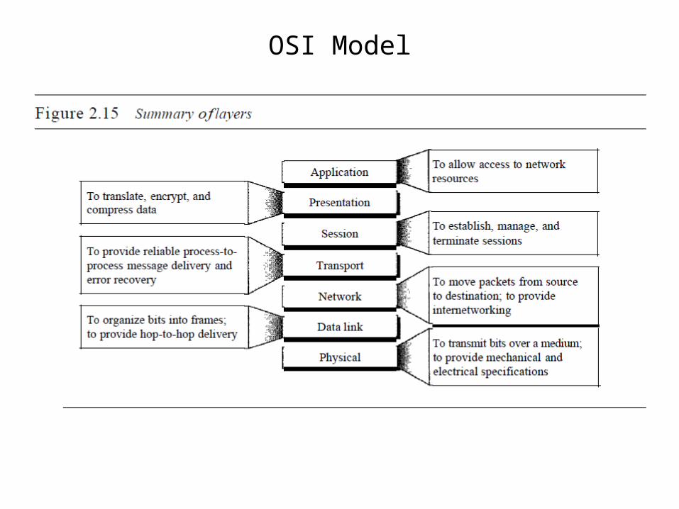
OSI Model
Error Detection
• Data transfer between two devices must be error free.
• Data Can be corrupted during transmission• A reliable communication system must have
capability to detect and correct errors.• Error detection and correction is implemented at
the data link or transport layer of the ODI model• Types of errors are
– Single bit errors– Multiple bits errors– Burst Errors
Error Detection
• Redundancy is used to detect errors– Vertical redundancy – Horizontal redundancy– Cyclic Redundancy