
Computer Analysis of Deflections and Stresses in Stage ... · Computer Analysis of Deflections and...
12
Computer Analysis of Deflections and Stresses in Stage Constructed Concrete Bridges Tony J. Herbert Director Maunsell & Partners Pty Ltd Melbourne, Australia The author is a principal of Maunsell & Partners Pty Ltd, which is the Australian arm of the Maunsell Consulting Group. He has more than 20 years of experience in the design of major bridge projects and has particular expertise in the application of state of the art computer techniques to engineering analysis and design. Mr. Herbert was a founding member and active for many years as a counselor of the Association for Computer Aided Design, based in Melbourne. He has worked as a consultant in the United States, Hong Kong and the United Kingdom at various times. Currently, he is a member of the American Society of Civil Engineers, the Institution of Engineers (Australia) and the Institution of Civil Engineers (Great Britain). 52 This paper presents a methodology and computer program for the analysis of stage constructed bridges and other two-dimen- sional prestressed concrete structures. The method uses step- by-step superposition of strains and accounts for time- dependent effects including creep, shrinkage and hardening of concrete, and relaxation of prestressing steel. Structural ele- ments comprise supports, hinges and temporary links as well as the concrete segments, and can be erected in any logical order. The computer program is described and used to illustrate the method with an example problem involving a simple three- span bridge. An important feature of the method is that it can be applied independently of a particular code of practice and the computer program demonstrates this by incorporating the provisions of six separate codes. T he computation of stage-by- stage stresses and deflections in concrete bridges is a tediou s, but essential, step in the design pro- cess. Concrete and prestre ss ing ten- dons typically exhibit nonlinear, time-dependent behavior which must be accounted for in the analysis pro- cedure. If the erection sequence is complex and alternatives have to be considered, then the computational requirements become so demanding that the use of computers becomes imperative. This paper describes a design ap- proach and a computer program which have been shown to be effec- tive by several years' design office and field experience in Australia, the United Kingdom and South East Asia. The bas ic approach is not new, but the method of implementation and the incorporation of several quite dif- ferent codes of practice will be of in- terest to many practicing bridge de- signers. The use of easily accessible micro- computers and their graphic di splay capability means that designers can work efficiently in isolated situations where normal computational facili- ties are not available. It also means that alternative erection sequences can be developed on site before refer- ence need be made to the designer. The computational approach is PCI JOURNAL
Transcript of Computer Analysis of Deflections and Stresses in Stage ... · Computer Analysis of Deflections and...

Computer Analysis of Deflections and Stresses in Stage Constructed Concrete Bridges
Tony J. Herbert Director Maunsell & Partners Pty Ltd Melbourne, Australia
The author is a principal of Maunsell & Partners Pty Ltd, which is the Austral ian arm of the Maunsell Consulting Group. He has more than 20 years of experience in the design of major bridge projects and has particular expertise in the application of state of the art computer techniques to engineering analysis and design. Mr. Herbert was a founding member and active for many years as a counselor of the Association for Computer Aided Design, based in Melbourne. He has worked as a consultant in the United States, Hong Kong and the United Kingdom at various times. Currently, he is a member of the American Society of Civil Engineers, the Institution of Engineers (Australia) and the Institution of Civil Engineers (Great Britain).
52
This paper presents a methodology and computer program for the analysis of stage constructed bridges and other two-dimensional prestressed concrete structures. The method uses stepby-step superposition of strains and accounts for timedependent effects including creep, shrinkage and hardening of concrete, and relaxation of prestressing steel. Structural elements comprise supports, hinges and temporary links as well as the concrete segments, and can be erected in any logical order. The computer program is described and used to illustrate the method with an example problem involving a simple threespan bridge. An important feature of the method is that it can be applied independently of a particular code of practice and the computer program demonstrates this by incorporating the provisions of six separate codes.
The computation of stage-bystage stresses and deflections in concrete bridges is a tedious,
but essential, step in the design process. Concrete and prestressing tendons typically exhibit nonlinear, time-dependent behavior which must be accounted for in the analysis procedure. If the erection sequence is complex and alternatives have to be considered, then the computational requirements become so demanding that the use of computers becomes imperative.
This paper describes a design approach and a computer program which have been shown to be effective by several years ' design office
and field experience in Australia, the United Kingdom and South East Asia. The basic approach is not new, but the method of implementation and the incorporation of several quite different codes of practice will be of interest to many practicing bridge designers.
The use of easily accessible microcomputers and their graphic display capability means that designers can work efficiently in isolated situations where normal computational facili ties are not available. It also means that alternative erection sequences can be developed on site before reference need be made to the designer.
The computational approach is
PCI JOURNAL

based on a step-by-step superposition of strains as described in several papers by Dr. Maher K. Tadros (University of Nebraska), and Dr. Amin Ghali and Dr. Walter Dilger (both of the University of Calgary). The method assumes that concrete creep is proportional to stress and thus the superposition of stresses and strains is valid. The stiffness method is used to determine the displacement and stress increments of the structure. The assumptions used on the time-dependent behavior of concrete are in accordance with commonly used codes of practice.
Although the effects of nonprestressed reinforcement can be included, uncracked concrete section properties are assumed at each step of the analysis. Therefore, no allowance is made for any reduction in flexural stiffness, and redistribution of internal forces in elements where net flexural tensile stresses theoretically exist.
In general, the time intervals for each stage are relative to the date that the first segment is erected and all intervals are individually specified relative to that date. Analysis time can be synchronized with any arbitrary time scale such as a construction program; however, the casting date is independent of both these parameters, the relationships being:
(a) Erection Date= Casting Date+ Age at Erection
(b) Age at Erection= Curing Period + Shrinkage Time Prior to Erection
(c) Project Date= Start Date+ Accumulated Time Intervals
These relationships may be illustrated graphically with an example. If shrinkage is to be investigated 90 and 990 days after erection begins, this could be modeled using either of the options shown in Fig. 2.
In most cases the simplest procedure is to set the curing period equal to zero, assume the first segment is cast on day zero and start the analysis on the day when it is erected. Time intervals will then be added cumulatively from the casting date.
Shrinkage that occurs prior to the erection of a segment may be significant in some cases and should be considered.
May-June 1990
CONCRETE MATERIALS
Concrete Modulus of Elasticity The elastic modulus or strength of
the concrete at 28 days is used in conjunction with the age of each segment to calculate the degree of hardening. In calculating the age of each segment, allowance should be made for the delay in aging due to curing and any effects of temperature on aging.
From the degree of hardening and the cement type, an effective concrete strength and hence modulus is calculated at each point in time using a loglinear interpolation. For each segment the mean modulus over each time interval (calculated using Simpson's Rule) is used to calculate the incremental creep and shrinkage deformations.
Creep of Concrete
Creep effects are cumulative and
Vl Vl
c 0 QJ .._ .._
+-' Constant Stress +-' Vl Vl
time
strain superposition is assumed (see Fig. 1 ). Curing period has no effect on the timing or quantum of creep effects.
If it is necessary to ignore all creep effects for a particular problem, this can be achieved by setting the basic creep coefficient to zero. This option should normally only be used to investigate the shrinkage of plain concrete. For concrete shrinkage where reinforcement is present, the restraint stresses caused by the reinforcement are subject to creep adjustment.
Shrinkage of Concrete
Shrinkage is considered to begin at the end of the curing period and it is assumed that the final value of shrinkage is not altered by the length of the curing period, merely delayed (see Fig. 2). Any allowance for the effects of special curing methods must be
]"" Strain ----
Elastic Strain
time
SINGLE LOAD APPLICATION
Vl c Vl
0 QJ 3 .._ .._ +-' +-' Vl Vl
INCREMENTAL LOAD APPLICATION Fig. 1 . Superposition of creep effects.
OPTION 1 Erect at Day 10, no curing.
OPTION 2 Erect at Day 30, cure for 5 days.
I Interval I (90)
10 100
z I .I'(~)~ I «
"' >-(/)
UJ
"' <(
"' z Cast iE
I I (/)
15 20
Fig. 2. Relationship of shrinkage to start and curing times.
Incremental strains can be summed
DAYS
DAYS
53

made in the basic coefficient. Thus, if a segment is cast on Day 0
with a curing period of 3 days, it is assumed that 7 days of shrinkage has occurred by Day 10.
Erection of an element before its curing period has expired is considered an unusual but allowable situation.
Allowance for varying humidity conditions may be made by modification of various concrete coefficients. For example, the construction (shortterm) conditions of a structure designed for one class of concrete, and having Stage 1 built in the dry season and Stage 2 built in the wet season, can be investigated by specifying two types of concrete which are identical except for the creep, shrinkage and thickness coefficients.
Prestressing Tendons
Prestressing tendons, comprising
single steel cables or bars, can be combined into "tendon groups" for analysis purposes. Each group is a set of identical cables or bars which are stressed at the same construction stage and having the same, or nearly the same, eccentricity at the section under consideration. Some averaging of eccentricities may be acceptable, depending on the accuracy of results desired.
The initial prestressing force in a tendon group is the total force in the group immediately after stressing. Due allowance must, therefore, be made for friction, anchorage draw-in and elastic losses.
Nonprestressed Reinforcement
The area of steel reinforcement should be taken into account but the inertia is usually significant only if bars are located in both the top and bottom of the section.
Section 2-.. x
'--~ ~
y
Lx Fig. 3. Segment notation.
Superstructure
J1 ~Prop Pier
Use of temporary ties in erection of a segmental arch
Fig. 4. Examples of temporary links.
54
~ ~J node
X, Y are global axes x, y are I ocal axes
Span-by- span erection of continuous bridges
STRUCTURAL ELEMENTS Segments
Segments are the basic concrete beam elements forming the final permanent structure and any number of segments can be erected in a stage. The only requirement is that when a segment is erected, it must conform to the normal rules of matrix structural analysis. For example, there must be sufficient support to each part of the structure to take out the rigid body modes of translation and rotation. It is quite permissible to erect a structure as a series of disconnected sub-structures which are joined at a later stage.
Fig. 3 depicts the segment notation. Where segments have different
section properties at each end, these are averaged for stiffness calculations. However, in subsequent computation of the stresses at each end actual properties are used.
Once erected, segments may not be removed from the structure.
The concrete density chosen for segments includes the weight of all prestressing steel and therefore should always be greater than the density for plain concrete. However, the weight of embedded steel reinforcement fs calculated separate I y.
Temporary Links
Ties, struts and tension/compression links are used to modify the existing structure. They are typically used to add external effects (temporary props) and forces (temporary cable stays) to the structure. Usually these temporary facilities will be removed in a subsequent construction stage.
Temporary links are elastic ties or struts and have no creep or shrinkage properties. They can be thought of as cables or rods hinged at both ends. Because temporary links have no flexural stiffness, the ends connected to supports must be restrained against the appropriate freedoms. The simplest approach is to fully fix the support.
If the weight of a temporary link is specified, it will be treated as an extemalload on the structure, applied at the link ends in the Y direction, and reversed when the temporary link is
PCIJOURNAL

removed from the structure. Temporary links (see Fig. 4) are
added to the structure in the first interval of a stage and subsequent load stages distribute the loads on the basis that the temporary link is an integral part of the complete structure. When temporary links are added to the structure in the same stage in which external loads are applied to the structure, those external loads will be distributed after the temporary links have been added.
A temporary link may have its load state altered or set to zero. The link will still remain part of the structure in later stages and loads may subsequently be distributed to it. When the link no longer contributes to the overall stiffness of the structure in subsequent stages it should be removed entirely.
The loaded state of an existing temporary link can be altered by calculating the necessary forces to be applied at either end of the temporary link to induce the required load. Initially this force is applied with the temporary link removed; then, after the internal forces have been redistributed, the temporary link is reinstated into the structure.
If a temporary link is to be added with a prescribed force in it Uacked cable), the procedure is to add it in a zero duration stage and change the force in the link in a further stage immediately afterwards.
Hinges
Sliding connections (translations) and hinges (rotations) may be specified between segments using hinge elements as shown in Fig. 5. For translational releases the degree of freedom being released may be skewed allowing inclined sliding between segments to be modeled. A skew angle can be specified if the local hinge translational freedoms are not parallel to the global axes.
Hinges are specified between two coincident nodes. Segment 3,4 might be connected to Hinge 4,5 which is then connected to Segment 5,6. When erecting segments that are separated by hinges, the hinge elements must be erected simultaneously to ensure continuity. Generally, hinges will be
May-June 1990
erected fully restrained and individual freedoms released later.
Until one or more freedoms in the hinge is released, the structure will behave as if the hinge did not exist; that is, full continuity exists between the connected segments.
Hinges may subsequently be released and reclamped in later stages but can never be removed from the model.
Supports
At any stage in the erection sequence a node may have one or more of its freedoms restrained. That node is then treated as a "support" and its status can be altered in subsequent stages. A fully built-in support will have its X and Y translation and its R rotation freedoms restrained.
A support may be created with a preset reaction Uacked support) or with a prescribed displacement. Prescribed displacements may be specified as absolute or relative (to the current deformation at that node).
To model the effect of a prescribed displacement, a unit load is applied at the support node of a version of the structure with the support removed. The final load to be applied is then calculated by scaling these results to achieve the user-specified displace-
ALL FIXED
X FREE
Y FREE
Fig. 5. Hinge models.
ment. This new force is subsequently applied to the structure in the normal manner.
After the forces have been distributed and the structure has taken up the new deformed shape, the new support is applied to the appropriate node. The support node is then treated as a normal integral part of the structure in subsequent stages.
At any subsequent stage, a support node may be changed by applying extra force, changing freedom conditions or setting prescribed displacements.
Spring supports are treated in a similar manner to normal supports, but a stiffness may be supplied at any of the available freedoms. Prescribed displacements may be set and reactions applied Uacked support) when the spring support is created.
Once a spring support is defined, its status may be modified in a subsequent stage by having its reaction or set changed (new prescribed displacement). Freedoms may be changed by fixing or releasing.
LOADINGS
External loads comprise concentrated loads at nodes and uniformly distributed loads on segments.
Dead load is calculated as the sum
R FREE
X FREE, R FREE
Y FREE, R FREE
55
of two components: (a) Concrete weight is calculated
as the product of concrete density of the mix, segment length and area (net of reinforcement).
(b) Steel reinforcing weight is calculated from the steel weight density, the segment length and total area of reinforcement.
Dead load is applied to the structure in the stage where the element is erected.
Loads due to prestress are calculated from the segment data, but it should be noted that:
(a) For any element, the prestressing force is considered to be straight between the defined positions at the ends of the element. If the eccentricities at each end are different, then the prestressing force will not be parallel to the centroid and the axial force in the element due to prestress will be less than the applied prestress force.
(b) Where a cable group comprises more than one cable and these cables are not stressed simultaneously, allowance must be made in the intial prestressing force for elastic shortening losses in the cables of the group caused by the stressing of the group cables.
(c) No allowance should be made to the initial prestressing for any deferred losses or elastic shortening losses due to other cable groups being tensioned in a later stage.
Prestressing tendons are assumed to be stressed at the beginning of a construction stage and are then immediately grouted. Section properties are adjusted for the presence of cables in the next interval and compatibility of strain between cables and the adjacent concrete means that cable forces are affected by strain changes in the concrete in addition to intrinsic relaxation.
External Loads
Although the focus of this paper is on dead loads and prestress, there will be other loads of an external nature which occur during construction, prior to service loads being applied to the structure. The most important of these will usually arise from construction activities and may include the
56
weight of cranes and other equipment. In some cases the use of ballast or kentledge may be necessary to limit stresses until later phases of construction are completed.
These loads differ from dead loads in that they are temporary and the analyst must be careful to remove them at the appropriate time.
Temperature Effects
Recent work on temperature effects (see Ref. 11 for example) has shown that, in some cases, loads equivalent to full service loads can be induced by temperature gradients in bridge girders. While a discussion of these effects is outside the scope of this paper, it is important that a careful analysis be done, particularly for segmental bridges.
Many design offices will consider differential temperature separately to construction staging and prestress effects using special computer programs for the purpose. This is appropriate because temperature loads are normally short-term and therefore secondary, time-dependent effects are negligible.
CONSTRUCTION STAGES
A "stage" is defined as the period during which the state of the structure in terms of segments, supports, temporary links and external loads is assumed to remain constant. Prestressing tendons active during a stage do not change but the force in them may, being affected by various time-de-
N Ul >-
Fig. 6. Section property calculations.
pendent effects. All stages start with changes to the
structure and loads being applied instantaneously. This is optionally followed by any number of user-specified intervals during which time-dependent effects such as creep and shrinkage gradually change the deflections and the distribution of load throughout the structure.
The number and length of intervals in a stage is selected with regard to accuracy requirements with larger intervals being used as the structure ages and time-dependent effects become less significant. Two or three intervals per stage will suffice in most cases, but more could be used in the final stage if very long-term effects are being investigated.
Since it is assumed that structural changes and loads are applied instantaneously, it follows that the specified preloads in tendons, supports and temporary links are those at the completion of all stressing and jacking operations. If these operations are to be done sequentially, and this effect is likely to be significant, then additional construction stages should be used.
The initial force for a group of tendons associated with a construction stage, is that after all tendons have been stressed and immediate losses, elastic, friction and anchorage drawin have been accounted for. Thus, if several tendons or tendon groups are to be stressed the analyst must adjust for elastic losses in the specified initial forces. More accurate modeling of this effect can be achieved by using additional stages. The effect of am-
>- ~ u >-
PC! JOURNAL

bient temperature during shrinkage can be taken into account by adjusting the age of each segment at erection as a temperature-corrected age as specified in the relevant codes of practice.
TRANSFORMED SECTION PROPERTIES
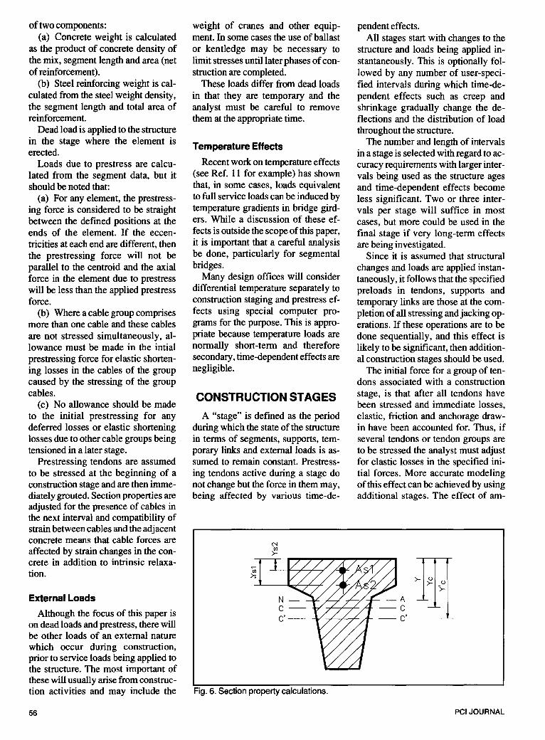
On the basis of the equations given below, the program calculates transformed section properties for use in stiffness and stress calculations (see Fig. 6). Refer to Appendix C for notation.
A/= Ac -A,1 A, = A:+n1 A,1 +~A,2 1/ = lc - A,1 (Y,I - Yc)2
- /,1 -A/ (Yc - Y/)2
I, = 1/ + Ac (Y- Yc)2 + 1,1 + n1 A,1
(Y,1 - Y)z + ~ A,2 (Y s2 - Y)z C - C = centroid of gross concrete
section C' - C' = centroid of net concrete
section (allowing for reinforcement voids)
N - A = centroid of transformed section
THE COMPUTER PROGRAM
CREAP is an acronym for Concrete Rheological Effects Analysis Program. It is a computer program which will analyze statically indeterminate concrete plane frame structures with full allowance for the effects of instantaneous and time-dependent development of stresses and strains. Although particularly well suited to the analysis of segmentally constructed bridges, CREAP will also be useful for many building frames and other prestressed concrete structures.
The program's capabilities include: (a) Staged construction in accord
ance with any user-defined sequence. During construction several substructures can be defined without necessarily being connected.
(b) The use of segments of varying ages and which are either precast or cast in place.
(c) Variation of support conditions during and after construction, including defined displacements and forces.
(d) Elastic, creep and shrinkage strains in the concrete and stress re-
May-June 1990
laxation of the prestressing steel. (e) Elements can be reinforced
with nonprestressed steel and/or subject to multistage prestressing.
(f) Temporary links can be added at any stage of construction and forces in them can be adjusted. Ultimately, these can be released and removed.
(g) Hinges can form part of the permanent structure and can be clamped/released during construction.
(h) Investigation of time effects in completed structures even though loads and support conditions are not altered.
(i) Analysis of nonlinear behavior due to deformation of the structure (second order effects).
(j) Runs can be terminated at any stage and intermediate results dumped for a subsequent restart.
Note that the structure does not necessarily have to be prestressed or even reinforced. By setting the basic shrinkage and creep coefficients to zero, all creep and shrinkage calcula-
0
" a. " 0::
Exit
Fig. 7. Simplified program logic diagram.
tions can be suppressed. Thus, by choice of appropriate parameters, CREAP may even be used for analyzing stage construction in materials other than concrete.
The overall logic of the computer program is shown in Fig. 7 in simplified form. It follows the TadrosGhali-Dilger approach set out earlier but has some special features to assist bridge designers. These are discussed below.
CODES OF PRACTICE
The main analytical features of CREAP are independent of any particular code of practice or design specification. However, there are many different approaches to the calculation of creep and shrinkage effects and, when attempting to investigate a model under different codes of practice, the user must be aware of differences in definition of concrete parameters.
Formulas, charts and coefficients for the following six codes have been incorporated into the computer program and can be selected by the user with a simple command.
• PCIRecommendations, 1975 • CEB-FIPModelCode, 1978 • National Association of Aus
tralian State Road Authorities, 1976
• Australian Standard 3600---1988 • British Standard 5400: Part 4:
1984 • The Civil Engineering Manual of
the Hong Kong PWD. The program is structured such that
additional codes can be easily added as needs arise.
PREPARING THE DATA
Data consists of two main sections. (a) A defmition of the basic struc
tural model in terms of coordinates, segment topology, materials and geometric properties. For convenience, gaps may be left in the node numbering sequence, corresponding to parts of the structure not yet erected (all nodes are renumbered internally prior to assembly at each solution step).
(b) Data describing the way in which the structure will be built. A
57

defmition of actions to be performed in stages- presented in chronological order and comprising a subset of the following:
• Addition of new segments using a numbering system which is consistent with the completed structure. Early stages of the model may well consist of a series of unconnected sub-structures.
• Addition, removal or adjustment of temporary and permanent supports. These supports may be spring or fixed and may have specified loads or displacements.
• Clamping and releasing of hinges.
• Application of stage prestressing and any external loads to the structure.
• Selection of the desired amount of output.
• Definition of time intervals within each stage at which the load stiffness equations are to be solved. Creep and shrinkage properties are linearly interpolated across any one interval so enough intervals must be chosen for this to be a realistic assumption (stiffness equations are solved once per interval).
Two reference axis systems are used- a global X-Y system for the definition of the model in space and local x' -y' systems for each segment.
A normal first quadrant X-Y system is used for the global axes. Models are usually coded with Node 1 at the left side of the model (nearest origin) and the structure is then numbered such that increasing node numbers appear left to right. However, this is not essential and the node numbering system is completely arbitrary.
For segment, hinge or temporary link data the local axes are fixed by the x' (centroidal) axis which goes from Node I to Node J in the element topology.
The program uses International System (SI) units throughout and all times, ages and intervals are measured in days.
COMPUTER RESULTS
Results appear in chronological
58
=-- /
Deflected shape before erection of segment
------d1
I
d2 I dT
dT = Total cantilever deflection d1 + d2 +d3
where d1
d2 d3
deflection at match point prior to erection of segment PHI X L incremental deflection due to. erection of segment
Fig. 8. Cantilever deflections.
order as defined by the stages in the data. Within each stage, the results will be printed at the start of the stage (immediately after the erection of any new segments changed support conditions, etc.) and at the end ofthe last interval within the stage. One or both sets of results may be suppressed.
Three sets of deflection results are output:
Incremental deflections are those occurring in the current interval due to load, support or structural changes, or time-related effects such as creep and shrinkage.
Cumulative deflections are simply the running totals of all incremental deflections since erection, or the time at which a particular node became part of the structure. For inplace construction or precast concrete units erected on falsework, the final cumulative deflections represent the shape which the structure would have if not precambered. Therefore, if the final shape is to follow the theoretical profile exactly, the structure should be precambered to the reverse of the tabulated cumulative deflections.
Cantilever deflections describe the shape of the structure when erected by adding segments progressively to the end of cantilevers, where each unit is fixed directly to its predecessor without first being supported on falsework. This means that
new nodes have an initial deflection not of zero (as it is when falsework i~ used), but related to the deflection (and rotation) of the attach-point node. This is illustrated in Fig. 8.
At the end of each run a complete index to the printout is produced. This includes the page number of the start of each set of results within a construction stage or interval. The index can be a very useful means oflocating particular results quickly since a large run can generate many pages of printout.
USE OF GRAPHICS
In addition to the normal tabular (printed) output, results can be plotted on graphics devices such as screens, plotters and some types of printer. The general procedure is to generate a special file, called a plotfile, and to use this as input to a utility program which produces the actual graphics output.
Three post-processors are available. They all produce similar end results but in quite different ways.
VIEW will display deflected shapes or stresses at each stage of construction using one screen per stage. Both types of results can be scaled and stresses which exceed a user-defined maximum are flagged.
CPLOT displays deflected shapes
PCI JOURNAL

directly on the screen and will then optionally redirect the same images to a plotter or other hardcopy device.
CREPACAD converts deflected shape and stress results to DXF (Drawing Interchange File) format which can be read directly by Auto CAD and several other popular microcomputer CAD systems. The advantages of this approach are twofold:
(a) The pictures can be manipulated, using the full power of a CAD system before final plotting. Thus, parts of the drawing can be rearranged, deleted, zoomed, notes can be added, and other refinements can be made.
(b) Micro CAD systems are widely available and support most of the commonly used screens, plotters and printers.
CPLOT and CREPACAD will arrange plots on the sheet for maximum scale depending on the shape of the completed structure. Low or flat structures such as bridges will be arranged in a vertical column from the bottom to the top of the sheet. Tall structures such as high rise buildings will be arranged in a row from left to right across the sheet.
SOFTWARE ENHANCEMENTS
The original CREAP program was completed in June 1980 and provided basic analytical capabilities for many structures encountered in practice. In 1984 a second release added features such as hinges, temporary links and a better method of specifying support changes during construction. It also improved the input/output formats and provided plotting interfaces. Additional analytical capabilities which are planned for the future include:
• Additional design codes • Temperature effects • Rigid links or "slave" degrees of
freedom • Extended segment load types • Stiffness matrices for tapered
segments • Direct specification of individual
tendons or groups of tendons • Calculation of friction and wob
ble losses • Stage stressing and destressing
May-June 1990
• Removal of segments from the structure
• Delayed grouting of tendons • Service loads It is expected that the demands of
users will dictate the contents and timing of future releases of CREAP.
EXAMPLE ANALYSIS OF THREE-SPAN BRIDGE
To illustrate some of the basic features of CREAP, a simplified example problem is presented below.
A symmetrical three-span bridge is shown in Fig. 9. Erection of the bridge starts at Pier 1 where segments are progressively placed on each side of the pier and tied together by post-
tensioning. While the cantilever erection is in progress, the cantilever is temporarily propped to produce a stable system to resist any unbalanced cantilever moments.
Span 1 is completed at Stage 3 by assembling the remaining segment on falsework and then stressing the bottom cables in the span. The prop near Pier 1 is then removed and the process is repeated for the other half of the bridge starting from Pier 2 at Stage 2.
The bridge construction is completed by dropping in the central segment and stressing the continuity cables in Span 2 while allowing horizontal movement at Pier 2.
Construction staging is illustrated in Fig. 10.
PRESTRESSING LAYOUT
SECTION STND HAUNCH
D 2.0 2.5 Ct 0.8 1.0 Cb 1.2 1.5 Area 5.0 5.5 Inertia 2.65 4.65
SECTION PROPERTIES
Fig. 9. Three-span bridge example.
PIER 1
STAGE 1 Q) @
f?Z0/4?'~p PIER 2
® ® STAGE 2 ruw4Z(:;:P
STAGE 3
® STAGE 5 l I ==I== I em l 1
NODES 4 5 6 7 8 9 10 11 12
3x10=30 I 2@10=20 I 5 1 2@10=20 I 3@10=30
Fig. 10. Construction stages for example bridge.
59

Material Properties
Prestressing tendons: E = 200 GPa (29,000 ksi) f.= 1.8 GPa (260 ksi) Area= 200 mm2 (0.31 in.2)
Concrete: Density = 2400 kg/m3 (150 lb/ft3) EcTd = 34 GPa (4930 ksi) Creep coefficient = 2.0 Ultimate shrinkage= 0.0003 Segments are assumed to be cured
for 3 days and then stored until transportation and erection at an age of 28 days. Each construction stage is 28 days.
Loads representing prestress and self weight are applied in each of the five construction stages. A superimposed dead load of intensity 45 kN/m is progressively applied over the whole structure.
Support conditions are changed in all stages.
Results of the analysis are presented graphically in Figs. 11 and 12.
PRACTICAL USE OF PROGRAM
The computer program described above has been successfully applied to the analysis of several major bridges in Australia, Asia and the United Kingdom. Although computer analysis can be efficiently applied to a wide range of bridge types and spans the benefits are greater where the construction sequence is complex and this tends to be the case for larger bridges.
Some examples from the authors' experience include:
Bowen Bridge, Hobart, Tasmania (Fig.13)
This match-cast segmental bridge was constructed as a series of balanced cantilevers and computer predicted deflections proved reasonably correct in practice. The central spans were 109 m (358 ft).
Mass Transit Overpasses, Kowloon Bay, Hong Kong
Tight geometric constraints at key sections meant that prestressing tendon profiles had to be kept within very narrow limits on these struc-
60
ing construction. tures. Successive adjustments were made to the profiles and reanalyzed using CREAP until stress limits required by local codes of practice could be achieved.
Waihai Bridge over Pearl River, Southern China (Fig. 15)
Barwon River Bridge, Geelong, Australia (Fig. 14)
Computer analysis was used in the design of this 82 m (269 ft) span bridge and was subsequently applied to the rapid evaluation of alternative erection sequences and programs dur-
The main spans of this interesting structure are balanced cantilevers spanning 110m (361 ft). Approach spans were launched from the abutments. The CREAP computer program was used extensively as a design aid and good agreement with predicted deflections was obtained during construction.
1~4 :t.:::::::: I s I ::::?::JI I ! rr:::P' I~ I 10 ~4
STAGE 5
c;::;;l ~I I~
STAGE 4
.r::::r;l I~ I 7 8 + 9
STAGE 3
2 3 4 4 s I 8 4
STAGE 2
3 l J
STAGE 1
Fig. 11. Deflected shapes for various construction stages.
Jo
Scale of mm
400
200
0
200
400
~-L Bottom Fiber Stress STAGE 5
~~ 11.1 STAGE 4
~~ STAGE 3
MPa
:OJ 20
STAGE 2
STAGE 1
Fig. 12. Top and bottom stresses for various construction stages.
PC! JOURNAL

Fig. 13. Bowen Bridge, Hobart, Tasmania.
Prestons Road Overpass, London, England
This overpass forms part of the Docklands Light Rail System and has a main span of 65 m (213 m). Its modest size makes it particularly amenable to microcomputer analysis where run times of a few minutes were experienced on AT class machines.
CONCLUSIONS
The incremental analysis technique originally developed by Drs. TadrosGhali-Dilger has been shown to be a highly effective and practical tool when programmed into appropriate computer algorithms and particularly when use is made of graphic displays and plotting devices.
Fig. 14. Barwon River Bridge, Geelong, Australia.
May-June 1990
All but the largest and most complex structures can be solved and displayed on basic microcomputer equipment making field use of the technique a practical reality. It is expected that state of the art 386 machines now becoming increasingly accessible to design engineers will make virtually any prestressed concrete bridge capable of microcomputer analysis for dead load and prestress.
Since time-dependent effects in concrete are notoriously unpredictable, further work is required to relate field measurements to the basic creep and shrinkage models which are built into the program. While these models are based on commonly used codes of practice, they are known to have limitations and a better understanding of the basic relationships will produce better predictions of overall bridge deflection behavior and stresses.
The CREAP computer program is an easy-to-use, practical tool which has been developed over several years in a design office environment. It can produce reliable results in minimal time and is particularly effective when alternative structures or construction sequences are to be evaluated.
61

REFERENCES I. Neville, A., Creep of Concrete: Plain ,
Reinforced and Prestressed, North-Holland Publishing, Amsterdam, 1970.
2. PCI Committee on Prestress Losses, "Recommendations for Estimating Prestress Losses," PCI JOURNAL, V. 20, No. 4, July-August 1975, pp. 43- 75.
3. Bridge Design Specification, National Association of Australian State Road Authorities (NAASRA), 1976.
4. Tadros, M. K. , Ghali, A., and Dilger, W. H., "Time-Dependent Analysis of Composite Frames," Journal of the Structural Division, ASCE, V. 103, No. ST4, Proceedings Paper 12893, April 1977, pp.871-884.
5. CEB-FIP, Model Code for Concrete Structures, Comite Europeen du Beton, Paris, and Federation Intemationale de Ia Precontrainte, London, 1978.
6. Tadros, M. K., Ghali A., and Dilger, W. H. , "Time-Dependent Stresses and Deformations of Segmental Structures," FIP 8th Congress, London, 1978.
7. Tadros, M. K., Ghali A., and Dilger, W. H., "Long-Term Stresses and Deformation of Segmental Bridges," PCI JOURNAL, V. 24, No. 4, July-August 1979, pp. 66-87.
8. American Association of State Highway and Transportation Officials (AASHTO), Standard Specifications for Highway Bridges, 13th Edition, Washington, D.C. , 1983.
9. BS 5400: Part 4: 1984, Code of Practice for Design of Concrete Bridges, British Standards lnsitution, Milton Keynes, United Kingdom, 1984.
10. AS 3600-1988, Concrete Structures, Standards Association of Australia, Sydney, 1988.
11 . Potgieter, I. C., and Gamble, W. L. , "Nonlinear Temperature Distributions in Bridges at Different Locations in the United States," PCI JOURNAL, V. 34, No. 4, July-August 1989, pp. 80-103.
APPENDIX ADEFINITIONS
In the context of this paper, the following definitions are used: CREEP - A phenomenon whereby strains in a material subjected to constant stress will gradually increase with time; thus, strain must be considered a function of stress and time. Concrete is a material which is particularly susceptible to creep effects and it is not uncommon for strains to increase by 200 percent over the ini-
62
Fig. 15. Waihai Bridge, China.
tial (elastic) strain. CREEP COEFFICIENT- The ratio of creep strain in the concrete to the elastic strain caused by a load applied at 28 days. CURING - The process of initial hardening of new concrete without drying. In "moist" curing, moisture loss is prevented by sealing or keeping the surface wet. "Accelerated" curing uses elevated temperatures, usually induced by steam, to achieve rapid hardening within say 18 hours, but the normal range of moist curing periods is from 3 to 7 days. HARDENING- The tendency of Young 's modulus to increase with the age of the concrete. HINGE - A structural element of zero length which can be released or clamped in various directions at any stage of construction. INTERVAL - A period of time during which loads and other conditions can be assumed to be constant for analysis purposes. This can vary from a few days during erection to months or years when time-dependent effects have stabilized. LINK - A temporary structural element capable of resisting axial load but not bending. NODE - A point, defined by X, Y coordinates, which is the end of a segment or possibly a support. SECTION - The cross section of a segment. Each segment has two sections defined - one at each end.
Where the two sets of section properties differ, the average is used in deriving segmental stiffness matrices, but actual properties are used in stress calculations. SEGMENT - A section of concrete structure considered to be erected as a unit. Could be one or several precast units or a section of in-place concrete. Segments are connected to one another at nodes which lie on the centroidal axis. SHRINKAGE - The property of concrete which causes dimensions to reduce with time, occurring irrespective of stress state. STAGE - An event in the construction sequence where segments are erected, supports, links or hinges are changed, or external loads are applied. STRUT- A temporary link which can resist only compression. SUPPORT - A node which is restrained against one or more freedoms, that is X or Y translation, or rotation. TENDON - A single prestressing cable (wires or multi-strand) or bar, enclosed in a separate sheath, and individually stressed. TENDON GROUP- A set of identical tendons which are stressed in the same construction stage and have the same, or nearly the same, eccentricity at the section under consideration. TIE - A temporary link which can resist only tension.
PC! JOURNAL

APPENDIXB-DATA FOR EXAMPLE THREE-SPAN BRIDGE
CREAP DATA PLOT DEMO. PLT TITLE SIMPLE 3 SPAN BRIDGE
CODEPCI
DEFINE 1 TENDON 1 1800 0.8 200
DEFINE 12 NODES 1 0/210/3 20 4 30/5 40/6 50 7 55/8 65/9 75 10 85/11 95/12 105
DEFINE 1 CONCRETE 1 1 2400 3 34 2-0.0003 1.5
DEFINE 2 SECTIONS 1 2.65 0 5.0 0 0 0.3 0 0.8-1.2 2 4.65 0 5.5 0 0 0.3 0 1.0-1.5
DEFINE 11 SEGMENTS S1114 1 11 3 80 1 0.0 23000 2 1 1 3 80 1-1.1 21000 S2114 212 2 60 1 0.0 17000 3 80 1-1.1 21000 312 2 60 1 + 0.7 15000 3 80 1-1.1 20000 S3 114 312 1 60 1 + 0.0 13000 2 60 1 + 0.7 15000 422 160 1 + 0.8 15000 2 60 1 + 0.9 14000 S4114 422 1 60 1 + 0.8 15000 2 60 1 + 0.9 14000 512 1601 0.0 17000 2 60 1 + 0.7 13000 S5 114 512 2 60 1 + 0.7 13000 5 80 1-1.1 23000 612 2 60 1 0.0 11000 5 80 1-1.1 22000 S6114 6 11
May-June 1990
5 80 1-1.1 22000 7 11 5 80 1-1.1 22000 S7 114 712 3 6010.011000 5 80 1-1.1 22000 812 3 60 1 + 0.7 13000 5 80 1-1.1 23000 S8 114 812 2 60 1 0.0 17000 3 60 1 + 0.7 13000 922 2 60 1 + 0.8 15000 3 60 1 + 0.9 14000 S9 114 922 2 60 1 + 0.8 13000 3 60 1 + 0.9 15000 10 1 2 2 60 1 0.0 16000 3 60 1 + 0.7 16000 S10 114 1012 3 60 1 + 0.7 15000 4 80 1-1.1 20000 111 2 3 60 10.0 17000 4 80 1-1.1 21000 S11114 111 1 4 80 1-1.1 21000 12 11 4 80 1 0.0 23000
STAGE 1 ERECT 3 4 TITLE 2 SEGS ON PIER 1 SUPPORT 4 ALL DEFINE 1 INTERVAL 28
STAGE 2 ERECT 2 58 9 TITLE 4 SEGS ON PIER 2 SUPPORT9ALL DEFINE 2 LOADS DIST3-45 DIST4-45 DEFINE 1 INTERVAL 28
STAGE3ERECT 1710 TITLE COMPLETE SPAN 1 SUPPORT 1 Y CHANGE SUPPORT 4 R FREE DEFINE 4 LOADS DIST2-45 DIST 5-45 DIST8-45
DIST9-45 DEFINE 1 INTERVAL 28
STAGE 4 ERECT 11 TITLE COMPLETE SPAN 2 SUPPORT 12Y CHANGE SUPPORT 9 R FREE DEFINE 3 LOADS DIST 1-45 DIST7-45 DIST 10-45 DEFINE 1 INTERVAL 28
STAGE 5 ERECT 6 TITLE COMPLETE THE BRIDGE CHANGE SUPPORT 9 X FREE DEFINE 2 LOADS DIST6-45 DIST 11-45 DEFINE 4 INTERVALS 28 225 730 2920 STOP
APPENDIXCNOTATION
As1 = area of reinforcement As2 = area of prestressing steel n1 = modular ratio (reinforcement) n2 = modular ratio (prestressing
steel) Ac = gross concrete area A'= net concrete area (allowing for c
reinforcement area) A, = transformed section area Ic = gross concrete inertia (about
C-C) Ic' = net concrete inertia (about
C'-C') Is = inertia of reinforcement
(about reinforcement centroid) I, = transformed section inertia
(aboutN-A)
INFORMATION ON THE COMPUTER PROGRAM
Further information on availability of the CREAP computer program may be obtained from the author at Maunsell & Partners Pty Ltd., 6 Claremont Street, SOUTH Y ARRA 3141, Australia.
63


![ANALYSIS OF STRESSES AND DEFLECTIONS IN SPUR GEAR · 2017-05-06 · 2.11. GRAPH SHOWING RELATIONSHIP BETWEEN LEWIS FORM FACTOR, PRESSURE ANGLE AND NUMBER OF TEETH [3] 3. CAD MODEL](https://static.fdocuments.in/doc/165x107/5e98519789b98b443834c26d/analysis-of-stresses-and-deflections-in-spur-2017-05-06-211-graph-showing-relationship.jpg)


