CAI: COMPUTER AIDED INSTRUCTION // CAL: COMPUTER AIDED LEARNING SOFTWARE

Computer-aided Planning and
Building Process
vorgelegt von Master of Science
Salem Buhashima Abdalla-Salem aus Libyen
an der Fakultät VI Planen Bauen Umwelt Institut für Architektur
der Technischen Universität Berlin zur Erlangung des akademischen Grades
Doktor der Ingenieurwissenschaften
- Dr.-Ing.-
genehmigte Dissertation
Promotionsausschuss:
Vorsitzender: Prof. Dr. rer.-nat. Rudolf Schäfer, TU Berlin
Berichter: Prof. Dr.-Ing. Klaus Rückert, TU Berlin
Berichter: Prof. Dr. techn. Karl-Heinz Bruhnke, Universität Leipzig
Tag der wissenschaftlichen Aussprache: 19. August 2009
Berlin 2009
D83


Acknowledgements
This work would not have been possible without the help and support
of Professor Rückert to whom I am very grateful. He provided me with
many helpful suggestions, important advice and constant
encouragement during the course of this research.
I also would like to express my sincere gratitude to professor Bruhnke
for being part of this research.
Special thanks are due to my entire colleague at the department of
Design and Structural, in particular the department secretary Angela
Isfort who was always there to help. Indeed, I would like to thank
anybody who has helped me by any means in achieving this research.
My grateful thanks go out to my family whose constant encouragement
and support has gotten me through this research.
I cannot end without thanking my country “Libya” for supporting me
throughout my study.
Thank you all
Salem Buhashima Abdalla-Salem
Berlin, 2009


Table of Contents
1 Introduction ................................................................................................. 1
2 State of the art of AEC digital planning (2006) .......................................... 5
2.1 BIM Applications within the AEC ............................................................. 14
2.2 Questionnaire surveys................................................................................. 15
3 Sharing data among the AEC industry - Software Compatibility &
Interoperability issues ....................................................................................... 19
3.1 Introduction ................................................................................................ 19
3.2 Objective ..................................................................................................... 21
3.3 Method and Procedures .............................................................................. 22
3.3.1 Exporting elements form MicroStation V8 to Nemetschek Allplan 2004. ........ 25
3.3.2 Exporting elements form MicroStation V8 to Architectural Desktop 3.3 ......... 31
3.3.3 Exporting elements form Allplan 2004 to MicroStation V8 ............................. 42
3.3.4 Exporting elements form Allplan 2004 to Architectural Desktop.3.3 ............... 51
3.3.5 Exporting elements form Architectural Desktop 3.3 to MicroStation V8 ......... 58
3.3.6 Exporting elements form Arch. 3.3 to Nemetschek Allplan 2004 ..................... 61
3.4 Conclusion and discussion .......................................................................... 65
4 VIRTUAL CITY EXAMPLE (VRCE) ..................................................... 69
4.1 Introduction ................................................................................................ 69
4.2 Objective ..................................................................................................... 72
4.3 Developing VRCE 2D plan ........................................................................ 73
4.4 Developing the VRCE Models ................................................................... 77
4.5 Visualization Tools and Methods ............................................................... 81
4.5.1 The CAVE ......................................................................................................... 81
4.5.1.1 Loading the VRCE to the CAVE .................................................................. 82 4.5.1.2 Problems and issues observed during visualization ...................................... 83

4.5.2 PC Screen Visualization (MicroStation) ............................................................ 84
4.5.2.1 Advantages and disadvantages of onscreen visualization ............................. 86
4.5.3 Google Earth Tools ............................................................................................ 87
4.5.3.1 Loading the VREC to Google Earth .............................................................. 88 4.5.3.2 Advantages and disadvantages of Google Earth visualization ...................... 95
4.6 Conclusions ................................................................................................ 97
5 Building Information Modeling (BIM) ..................................................... 99
5.1 Background ................................................................................................. 99
5.2 Objective ................................................................................................... 101
5.3 What is BIM? ............................................................................................ 101
5.4 Benefits of employing BIM ...................................................................... 106
5.4.1 Benefits during the design phase...................................................................... 109
5.4.2 Benefits during the construction phase ............................................................ 112
5.4.3 Benefits during the management phase ............................................................ 114
5.4.4 Benefits during Construction handover ........................................................... 116
5.4.5 More BIM benefits ........................................................................................... 119
5.5 Barriers to the adoption of BIM in the AEC industry ............................... 122
5.5.1 Transactional Business Process Evolution ....................................................... 124
5.5.2 Computability of Digital Design Information .................................................. 126
5.5.3 Meaningful Data Interoperability ..................................................................... 126
5.6 BIM Production ........................................................................................ 129
5.7 BIM Software Solutions and Tools .......................................................... 131
5.7.1 Bentley ............................................................................................................. 132
5.7.2 NavisWorks ..................................................................................................... 133
5.7.3 Google SketchUp ............................................................................................. 134
5.7.4 Autodesk .......................................................................................................... 134
5.7.5 Vico .................................................................................................................. 135

5.7.6 Tekla ................................................................................................................ 136
5.7.7 Nemetschek ..................................................................................................... 136
5.8 Types of BIM ........................................................................................... 137
5.8.1 First category: BIM according to Participants ................................................. 137
5.8.1.1 Single BIM (x1) .......................................................................................... 137 5.8.1.2 BIM (x2) ..................................................................................................... 138 5.8.1.3 BIM (x3) ..................................................................................................... 139 5.8.1.4 Multiple BIM .............................................................................................. 140
5.8.2 Second category: BIM according to Tools ...................................................... 141
5.8.2.1 Object-Oriented CAD systems (OOCAD).................................................. 141 5.8.2.2 Parametric building modelers ..................................................................... 143
5.9 BIM issues and standardizations .............................................................. 145
5.9.1 NBIMS (National Building Information Model Standard) .............................. 146
5.9.2 IFC (Industry Foundation Classes) .................................................................. 148
5.9.3 CIS/2 and IFC .................................................................................................. 150
5.9.4 NSC (The United States National CAD Standard) .......................................... 152
5.9.5 COBIE (Construction Operations Building Information Exchange) ............... 153
5.9.6 SDNF (Steel Detailing Neutral Format) .......................................................... 154
5.10 Related Work (Real life situations and examples) ................................... 155
5.10.1 U.S. Army Corps of Engineers (USACE) is going BIM ................................. 155
5.10.2 New innovative office building in the heart of Vilnius, Lithuania .................. 157
5.10.3 Denver Art Museum Expansion ...................................................................... 160
5.10.4 Park Hospital in Novi, Michigan ..................................................................... 162
5.11 Case Studies .............................................................................................. 164
5.11.1 Hilton Aquarium, Atlanta, Georgia: ................................................................ 165
5.11.2 One Island East Project, Hong Kong: .............................................................. 166
5.12 Conclusion ................................................................................................ 167
5.12.1 Who Owens BIM? ........................................................................................... 167

5.12.2 Work in a Multidisciplinary Coordination ....................................................... 168
5.12.3 Legal and Liabilities Issues .............................................................................. 168
6 A proposed BIM System ......................................................................... 173
6.1 System Architecture.................................................................................. 174
6.2 System components .................................................................................. 176
6.2.1 System Input .................................................................................................... 176
6.2.1.1 Architectural model ..................................................................................... 176 6.2.1.2 Structural model .......................................................................................... 176
6.2.2 System Output .................................................................................................. 178
6.2.2.1 Visualization ............................................................................................... 178 6.2.2.2 Documentations ........................................................................................... 179 6.2.2.3 Drawings and Models.................................................................................. 179
6.2.3 The proposed BIM System in Action ............................................................... 180
6.2.3.1 Extracting visualization from the BIM ........................................................ 180 6.2.3.1.1 On-Screen Visualization .................................................................... 181 6.2.3.1.2 Google Earth Tools ............................................................................ 185
6.2.3.1.2.1 Visualizing the BIM in Google Earth Environment ................... 185 6.2.3.1.3 3D Model in PDF Files (PDF Images) .............................................. 190
6.2.3.1.3.1 Inserting BIM into a PDF document .......................................... 191 6.2.3.1.3.2 Advantages and disadvantages of 3D plot in PDF ..................... 192
6.2.3.2 Extracting Documents from the BIM .......................................................... 194 6.2.3.2.1 Quantity take-off (Quantity Estimates) .............................................. 195 6.2.3.2.2 Reinforcement Details and Specifications ......................................... 203
6.2.3.3 Drawings and Models.................................................................................. 204 6.2.3.3.1 Architectural Drawings ...................................................................... 205 6.2.3.3.2 Structural Drawings ........................................................................... 207
6.2.3.3.2.1 Reinforcement Drawings ............................................................ 207 6.2.3.3.3 3D Models ......................................................................................... 210
7 Discussing the results .............................................................................. 211
7.1.1 Outputs break down ......................................................................................... 213
7.1.2 Distributing BIM results among targeted disciplines ....................................... 215

7.1.2.1 Results for Architects ................................................................................. 215 7.1.2.2 Results for Structural Engineers ................................................................. 217
7.1.3 Managing Changes and Modifying Process .................................................... 218
7.2 Conclusion ................................................................................................ 220
8 Overall Conclusions and Recommendations .......................................... 223
8.1 Recommendations .................................................................................... 225
9 References and Bibliography
10 List of Figures
11 List of Tables


Computer-aided Planning and Building Process
1
1 Introduction
In this dissertation, I wish to investigate and evaluate current state of
computer aided planning and building process in today’s Architecture,
Engineering and Construction (AEC) industry activities. It is a
descriptive work of newly emerging technologies and approaches to
design, construction and facility management that offer a great
potential of enhancing productivities, reducing project cost and project
delivery time and improving cooperation and communication between
project’s participants. Thereby, a much higher degree of co-ordination
and communication is anticipated during the constructing of a project
from design to actual construction to finally handing the building to a
facility manager.
While these technologies are opening up new methods of
communication and collaboration between projects’ participants that
were just not possible a few years ago, they are far from fully utilized
and advantages/benefits are not fully realized by the AEC industry.
Therefore, the main focus of this research is to provide an in-depth
understanding of these newly emerging technologies and approaches,
issues associated with their implementations, and their impacts and
effects on the AEC industry’s individuals and organizations.
The aim is to discuss two of the most promising techniques that have
huge impact on the AEC industry productivity and performance which
are virtual reality (VR) and building information modeling (BIM).
However, both techniques are based on computer’s applications which
are generally developed independently by different vendors with
different set of goals; and this is coming rather cumbersome and
Computer-aided Planning and Building Process
2
deterring the industry away from full acceptance. Partially, in the case
of CAD applications that are redirected for VR purposes which are
widely used by the AEC industry. Typically, these applications
(software) are developed solely by vendors who are mostly focusing on
getting nice pictures and aiming to reduce rendering time required, and
not thinking enough about sharing the data with other similar
applications. This has promoted hundreds of tools and applications that
promise compatibility but not full compatibility as they claim which
held back the AEC industry as a whole from gaining full advantages
and benefits awaited.
Therefore, interoperability, compatibility and data-sharing among the
AEC participants will be the subject of chapter three of this
dissertation. The focus is to explore some of the most commonly
encountered CAD tools that are widely used in the AEC industry to
demonstrate and elaborate on communication and data sharing issues.
Mainly, software applications those are locally available at Berlin
University of Technology (TUB).
Chapter four will focus on VR implementation within planning and
development process. The motive is to explore existing virtual cities
approaches and examples, whereby a Virtual Reality City Example
(VRCE) will be developed and explored. The VRCE is based on
“Hashtgerd Newtown” 2D plans which are available through an
educational agreement between the Building and Housing Research
Center (BHRC) in Iran and the TUB to establish collaboration on
academic and research related development activities. The aim is to
develop a 3D-city-example to illustrate and demonstrate new
visualization ways and methods that are now available through
emerging technologies and applications including, Google Earth, the
CAVE, etc.

Computer-aided Planning and Building Process
3
Building Information Modeling (BIM) definitions, background, and
implementation issues and effects will count for chapter five. BIM is
not only changing the way buildings look, function and built, it is
supposed to be the only source of information about a building from
planning through construction to its future management. It also
promises the production of high quality construction documents,
predicting performance, cost estimation and construction planning.
Hence, BIM is a building model based technology linked with a
database of project information to enable seamless communication
between all stakeholders associated with the construction process.
However, there are considerable benefits and advantages BIM can
offer which will be discussed in more details throughout this chapter as
well as disadvantages and obstacles. Also, other peoples experience,
case studies and examples of successful projects which has been
drawing from a range of sources, will be provided and discussed as
well.
In chapter six, a BIM system will be proposed based on a proposed
modern office building in Iran to generate building abstractions such as
plans, sections, elevation, details, and schedules. The proposed BIM
system will consist of two 3D models of the office building
(architectural and structural models) which will be designed and
developed using Bentley’s MicroStation TriForma software. This
chapter explores the proposed BIM system in which several documents
and views will be extracted directly from the system using various
approaches and methods.
Discussing the results and findings of the proposed BIM system will be
presented in chapter seven as well as categorizing the results according
to disciplines and providing an overall system outputs chart. In
addition, the most encountered issues and difficulties that obstruct BIM
adaptations and endorsement industry wide will be discussed.

Computer-aided Planning and Building Process
4
Finally, a brief conclusion on the effect of these new emerging
technologies on the AEC industry and how the industry is coping with
them is to be presented including final thoughts and recommendations.

Computer-aided Planning and Building Process
5
2 State of the art of AEC digital planning (2006)
The AEC industry has being using CAD for a long time now, but that
is only electronic drafting. While the advantages of CAD has been
well established and proven including efficiencies in drawing reuse,
organization, revisions, quality and consistency, etc. it is only an
electronic pencil and paper [10]. Though, CAD has greatly expedited
the process of drawing production and significantly improved the
accuracy of drawing over traditional methods, these drawings and
documents are not “intelligent” which store information about the
building systems and components [63]. In addition, CAD describes a
building by independent 2D views such as plans, sections and
elevations which mean editing one view requires that all other views
must be checked and updated. This process is prone to errors as well as
a major cause of poor documentation [73]. Considering the large
number of people and documents involve in a construction project
these are some of the issues related to the use of IT within the AEC
industry [49]:
• During the design phase:
Usually a construction project starts with the architect who
proceeds through a series of phases including schematic design,
design development, and contract documents. Next with the help
of other project team, the structural, HVAC, piping, and
plumbing components are designed. Then, the final set of
drawings is sent out to contractors for bidding. In most cases
the winning contractor, before work begin, has to redraw some
of the drawings to reflect the construction process and the
phasing of the construction work. Also, the subcontractors and
fabricators must generate their own “shop drawings” to reflect

Computer-aided Planning and Building Process
6
accurate details of certain elements, such as precast concrete
units, steel connections, wall details, piping runs, etc. However,
if these drawings are inaccurate or incomplete, or if they are
extracted from a drawing that already contains errors or
inconsistencies, then expensive and time-consuming conflicts
occur in the field.
• During the construction phase:
The inconsistency, inaccuracy, and uncertainty in the design
phase make it difficult to fabricate materials offsite. Therefore,
most fabrication and construction must be done onsite and only
when certain conditions are well known. This is costly, time
consuming and prone to errors process that would not occur in a
factory environment where cost and quality are better controlled.
Additionally, several changes are made to the design during the
construction phase due to previously unknown errors which
need to be resolved by the project’s team. This involves a
“request for Information (RF) which must be answered by the
architect and a “change of Order (CO) to notified all impacted
parties about the changes. In fact, these changes and resolutions
usually lead to legal disputes, promotes extra costs and delays.
• During the management phase:
After the construction is finished, the final contractors and
drawings are produced to reflect the as-built changes, which are
handed to the owner along with all manuals for installed
equipment. However, this information is conveyed to the owner
in 2D (on paper) which the owner must invest a great deal of
effort to relay all relevant information to the facility
management team charge with the maintenance and operating
the facility.

Computer-aided Planning and Building Process
7
In addition, the great number of participants involved in the planning
and construction of a project makes communication and coordination a
complex process to deal with [23]. Much effort has been put into
facilitating communication and collaboration among participants in a
construction project. In fact, the AEC industry is realizing this issue
and has been in general investigating and investing into ways,
techniques and approaches to improve collaboration and
communication among project’s team. This has led to BIM as one of
the most promising development in the AEC industry. Goldberg [71]
stated that: “We can't discuss digital design in the AEC industry
without mentioning BIM”. Thus, BIM is the best example of emerging
new technology today which is expected to drive the AEC industry
towards a “Model Based” process and gradually move the industry
away from a “2D Based” process. The “Model Based” process is where
the building will be built virtually before even actual construction starts
and it is also called Virtual Design and Construction (VDC) [70].
Using BIM (sometimes referred to as digital models) during the design
phase enable the design team to resolve systems-integration problems
during design, long before the project goes into construction in which
potential cost savings is realized [28]. Obviously, having all project
data in a single, updatable database would make data and accuracy
easier to manage and integrate all aspects of the project during the
design phase [27]. This also should provide contractors and
construction process participants during the construction phase more
complete as well as more effective representation of design intent. It
also means, there is a greater chance that the finished project will look
like the completed 3D model [16]. In addition, DeStefano [18] believes
that there is also the opportunity to import a digital model directly into
a fabricator’s shop drawing applications in which this data can be also
used to drive automated fabricating machinery and eliminate paper

Computer-aided Planning and Building Process
8
shop drawings. This allows fabricators to reduce waste because of
optimization of tasks such as cutting of sheet metal and pipe can
benefit from all scrap pieces.
As a management tool, the designer could generate data from the
model for use in calculating a wide range of performance, such as
heat/loss gain, day lighting effects, air flow, emergency routs,
structural performance and financial feasibility which means creating a
closer linkage between analysis and design process [31]. Smith [13]
implies that once the digital model of a facility is completed it will be
delivered to the operator and sustainer of the facility and any
modifications or improvements will be recorded in the model. Thus,
the model is the reliable source and will be utilized throughout the life
of the facility to plan and tackle any modifications and changes.
However, while utilizing BIM software and tools is quickly becoming
commonplace among design architects, many structural engineers are
hesitant to tackle three-dimensional representation of large, complex
projects. In fact, BIM has not been accepted without reservation in the
AEC community, especially by structural engineers who do not see an
immediate need to make the switch because their general clients are
architects and contractors who are already used to visualizing projects
from 2D drawings; even though embracing BIM by structural
engineers firms can streamline efforts and eliminate errors. On the
other hand, BIM is being quickly endorsed by architects as a way of
presenting their work in an easy-to-understand format to owners and
developers who are usually not able to read plans.
Traditionally, engineers would design 3D model of the project before
even considering loads and seismic issues, then drafters would build a
2D model to incorporate elevations and details. Now, using BIM,
drafters and engineers are sharing the same model to supplement it

Computer-aided Planning and Building Process
9
with their data which integrates drafting and engineering processes, as
both teams share the same 3D model.
However, bringing BIM in a firm requires skilled staffs that can perfect
the tool which requires a great amount of training effort, since skill set
is different from commonly used drafting programs requirement. Firms
realizing that a considerable effort of training is necessary to endorse
BIM technology; although, the learning curve and associated costs will
be steep in addition to significant software costs and new hardware that
are required such as bigger screens. AGC [70] published a guide to
BIM for contractors, which implies that generally companies are
accepting the initial cost and loss of productivity associated with initial
learning curve. Thus, firms who have succeeded the initial learning
process (6 to 8 months) experience such benefits including
improvement in productivity, lower warranty costs, fewer field errors
and corrections, etc. These advantages offset the costs with time and
could actually reduce them. Additionally, there are software tools that
combine models produced in different design packages into one file, to
be viewed as one composite model. However, the use of BIM does not
have to include the entire project, whereas in some cases, many
contractors who are involved in projects with intelligent models do not
even realize that. In fact, many designers, suppliers and contractors are
using digital models for their own benefit and not sharing the data with
other project participants. Therefore, the use of BIM is encouraged
even for a certain portion of the project, such as the structural steel or
the mechanical systems.
One company Cary Kopezynski & Co. (CKC) is using 3D modeling
approach in the design of the 20-storey Hyatt tower in downtown
Bellevue for the first time on any of its projects. In fact, project’s
architect and general contractor are using BIM tool as well, allowing
for a collaborative work that has been highly valuable on a project with

Computer-aided Planning and Building Process
10
a detailed design and a number of complicated connections. The
number of complex connections associated with the design, as well as
other construction activities on site, proved the use of BIM to be even
more appropriate. This could have been achieved using traditional 2D
drawings but would have required much more effort. Designers were
able to study different design ideas and thoughts before extracting the
details and studying the plan using BIM. In addition, using BIM has
helped designers to avoid structural conflicts with adjacent buildings
by identifying common foundation footings and other shared elements.
However, many project components, such as floor models, still require
2D drawings as well as moving back and forth between 3D and 2D
drawings which has been more challenging than expected. Also, line
weights which represent certain components in the plan are not
conveyed by the BIM to the 2D drawings correctly requiring
considerable efforts to correct. What is more, sharing drawings with
other project participants has proven to be a difficult task not as simply
attaching a file to an email document [65].
Also, Condon [68] acknowledges that with its clear benefits and cost
savings opportunity, BIM is not widely spreading among engineers and
managers. One reason is during the design and construction phases,
architects, engineers, and construction managers are not willing to
spend time in creating a BIM that does not substantially help them to
accomplish their jobs; but will be useful in the operations phase. Also,
they are discouraged by absence of universal standard for digital design
drawings. Now days, there are many different proprietary format with
varying levels of functionality which hinder widespread of BIM. For
example, a 3D model developed using one software package may not
be usable in another company using different software package.
Therefore, developing a universal BIM format that can be useable by
other software programs will be a significant challenge. He also argues
Computer-aided Planning and Building Process
11
that many architects are using CAD software just as a way of
producing a “picture” for printing on paper. In fact, until architects start
using CAD to its fullest capability, BIM will not be a reality. However,
facility owners and managers who will be benefiting most from BIM
are able to apply the pressure needed for all project team to adopt and
use BIM standard. Meanwhile, support for BIM technology among
owners and managers has been slow due to a lack of information and
understanding. Now this is changing because one of the largest facility
owners in the world (the United State government) is committed to
gaining benefits offered by BIM. However at an international level, it
will undoubtedly take years to evolve fully and be widely adopted
although remarkable progress has been achieved by the National
Institute for Building Sciences (NIBS) at the end of 2006 to form the
National BIM Standard (NBIMS).
Many believe that the problem of BIM and overall consensus involved
was not in the technology or in learning it, but rather the change of the
business process that result from transition to BIM. An estimated 70%
of the change required to bring BIM to a firm is going to be cultural,
while the technology part will be only 30% of it. Example of firms
experiencing transition to BIM is the GSA (US General Services
Administration, the largest builder-owner of federal projects in the
USA). The size of the company causes them to move slowly towards
BIM however, they are trying to be as adaptive and flexible as possible
and are committed to BIM. Another practical example is driven by
Walt Disney Engineering who experiencing simplicity in transition to
BIM in the last 18 months (as of writing of this article) due to the
rapidly changing pace of technology. Most likely, this rapid change of
technology will accelerate in the future allowing for smoother and
easier transition to BIM than is currently anticipated [69].
Computer-aided Planning and Building Process
12
In fact, the utilization of BIM in the AEC industry to improve the
planning, design and construction process is increasingly being referred
to as Virtual Design and Construction (VDC). However, whether it is
called “BIM” or “VDC”, this is the future of the AEC industry.
Stockholders, who haven’t adopted this technology yet, are encouraged
to at least start familiarizing themselves with the key terms and current
available tools and applications to provide them with a good
framework for gathering knowledge on the subject and better
endorsement preparation when the time comes. Yet, BIM is a tool
which is made available mainly by recent advances in computer
hardware and software. It may change the ways a project is viewed,
designed and defined, but it will not change the core responsibilities of
each member of the project team. Most importantly, the responsibilities
of project’s team members remain unchanged and they thoroughly
understand the nature, value and precision of the information being
conveyed. Now days, BIM tools that can ensure coordination between
project participates are available, when applied appropriately costs and
construction time are reduced [70].
Surprisingly, not many AEC professionals are aware of the BIM or
information extraction trends. Although the AEC industry has long
moved to CAD (that is only electronic drafting tool and far from the
idea of BIM) handful have pursed full 3D modeling with great vigor,
and even fewer adopted BIM and information extraction, even though a
great deal of time and money have been invested in BIM by the AEC
software industry. This is mainly because of the AEC is familiar with
2D CAD drafting tool and many know how to use them well, whereas,
BIM software are much more complex and hard to master. Yet, BIM
software solutions increase productivity immensely and provide
visualizations, sections and elevation, etc. The author mentioned two
major barriers that are blocking the widespread adoption of digital

Computer-aided Planning and Building Process
13
modeling within the AEC industry. The first obstacle is the liability
issue associated with the extraction of digital data directly to product
acquisition stream. For example, if the designer (architect) places two
items (windows) in the same position and they are order electronically,
who would pay for the extra window? In addition to who would pay
the architect for the additional effort to produce the digital model?
The second hurdle is not the capability of the new BIM software, but it
is the training needed to master the program. Already mentioned, BIM
software are complex and difficult to master, and professionals usually
don’t have extra time to implement new BIM solutions. Indeed the new
BIM program will usually require a master builder operator – someone
who has the knowledge on how buildings are built – but few exist. In
fact, experienced AEC personals have good knowledge on how to
construct a building; however they are generally don’t know how to
operate the software productively. Nevertheless, despite these obstacles
and hurdles, it’s inevitable that the AEC industry will be driven
towards 3D modeling and BIM. But the question is how long will it
take and which tool will become the industry standard [72].

Computer-aided Planning and Building Process
14
2.1 BIM Applications within the AEC
Azhar among others [73] and Birx [87] identify the following purposes
the AEC industry could use BIM technique for:-
• Visualization: visualization is the core of BIM which offers
rendered pictures of the project in-house with a little effort.
• Fabrication/shop drawings: users can easily extract shop
drawings for various building systems, as in the case of the sheet
metal ductwork shop drawing which can be quickly produced
upon completion of the model.
• Code reviews: the BIM model could be used by fire departments
and other officials to review their building projects.
• Forensic analysis: forensic analysis is made easy by adopting
BIM techniques to graphically illustrate potential failures, leaks,
evacuation plans, etc.
• Facilities management: renovations, space planning and
maintenance operations are type of services offered to facility
management department by BIM.
• Cost estimating: a feature that is built-in BIM software to allow
for automatically extracting material quantities and
incorporating any changes that made to the model.
• Construction sequencing: a BIM can be used to produce material
ordering, fabrication, and delivery schedules for all building
components.
• Conflict, interference and collision detection: since BIM are
created to scale, in 3D space, interferences of building systems
can be visually checked which can verify that piping does not
interfere with steel beams, ducts or walls for examples.

Computer-aided Planning and Building Process
15
2.2 Questionnaire surveys
Azhar among others [73] discussed the role of BIM in the US
construction industry and academia based on the results of three
questionnaire surveys as follow:-
The first survey was conducted by Kunz and Giligan [74] to determine
the value from virtual design and construction (VDC) or BIM use and
factors that contribute to success which yield the following findings:
1. Increase BIM usage across all phases of design and
construction during the last one year.
2. BIM is being used by all segments of the design and
construction industry which operate throughout the US.
3. Construction documents development, conceptual design
support and pre-project planning services among most
application areas of BIM.
4. Currently, the use of BIM tools for 3D/4D is dictated by
planning and visualization and clash detections.
5. Overall risk distributed with a similar contract structure
are reported to be decreased using BIM.
6. BIM helps firms to increase productivity, better of
project’s team engagement and reduce contingencies.
7. Also reported that there is a lack of skilled building
information modelers in the industry and demand will
grow over time.
The second survey is conducted by Khemlani [75] to identify the most
urgent requirements that AEC professionals would like BIM tools to
satisfy which are summarized to the most important 10 requirements as
follows:-

Computer-aided Planning and Building Process
16
• Full support for producing construction document to
eliminate the need for other drafting applications.
• Smart objects that can connect and related to other objects.
• Provide object libraries.
• Support multi discipline working on the same project.
• Provide help and supporting documentation, tutorials and
other learning resources.
• Ability to deal with large projects.
• Capability to serve multi-disciplinary team (architecture,
structural engineering and MEP).
• Direct integration with other tools such as energy analysis,
structural analysis and project management programs.
• Full compatibility with Industry Foundation Classes (IFC).
The survey concluded that the AEC industry is still relying on
drawings for conducting its activities of designing and construction.
However, AEC professionals are also aware of the capability of BIM
for more efficient and intelligent modeling by emphasizing on smart
objects that maintain connection and relation with other objects as well
as the availability of object libraries. Also indicated by participates
who required a BIM application that not only leverages the powerful
documentation and visualization capabilities of a CAD platform but
also to support multiple design and management operations. However,
BIM technology is still in the stage of development and application in
the market are continuing to evolve as they try to response to user’s
specific demands.

Computer-aided Planning and Building Process
17
The third survey was carried out by Dean of the department of
building science, Auburn University in 2007 to examine if BIM should
be taught as a subject to the construction management students. The
survey targeted general contractors and ASC construction management
programs in the Southeast. According to responds of participants, the
construction management program should teach BIM to their students
and here are the main reasons behind this conclusion:
• About 70% of the industry participants either using or
considering using BIM which indicate using this technology is
going to increase.
• About 75% of survey participants consider hiring candidates with
BIM skills over candidates without BIM skills.


Computer-aided Planning and Building Process
19
3 Sharing data among the AEC industry - Software
Compatibility & Interoperability issues
3.1 Introduction
Fragmentation of the Architecture, Engineering, and Construction
(AEC) industry is the direct cause of problems and issues related to
sharing information among projects participates, especially exchanging
design data. Young Jr. among others [1] anticipated the unprecedented
technology revolution that the AEC industry is experiencing today.
This is marked by the thousands of custom and commercial
applications being deployed in uncoordinated way by tens of thousands
of firms on over a huge number of projects every year. These
applications although powerful as they are in their own right, they held
the AEC industry as a whole from gaining benefits because these tools
don’t pass information seamlessly among themselves. As claimed by
Day [83], vendors sell their products on the basis of what they are can
do, and when advertising, they exaggerate their capabilities to look
very impressive indeed. However, individuals and firms have reported
a huge gap between potential and actual use of these applications.
Thus in today’s collaborative environment, projects teams are starting
to work and communicate more effectively for the overall benefit of
both their companies and their projects, so their tools need to evolve to
support this new way of doing business. However, there are many
design tools evolving today which are used by the AEC industry that
promises compatibility but not full compatibility as the claim.
Therefore throughout the last decade, researches in this field focus on
the enhancement of interoperability and industry-wide standards to

Computer-aided Planning and Building Process
20
support the development of industry tools and applications. One of the
most recently emerged technologies the AEC has adopted and being
discussed here is Virtual Reality (VR) technology. In recent years, the
emerging and fast growing (VR) technology has yield several
interesting visualization techniques, tools and applications. These
include immersive and Non-immersive VR tools such as, HMD (Head
Mounted Display, VR glasses, the CAVE (Cave Automatic Virtual
Environment), the BOOM (Binocular Omni-Orientation Monitor) etc.
as well as several CAD software applications that capable of
producing VR environment, such as MicroStation, Nemetschek, 3.3,
SuperScape, MultiGen-Pardigm, Autodesk, etc.
However, despite the advances in VR techniques and tools, data
exchange between these tools (often refer to as interoperability) is an
important issue that hampers the full usefulness of this technology.
Lack of interoperability could have great effects on both firms and
applications users, in which they could face unexpected problems and
heavy costs once it comes to updating or shifting to another
application. This mainly due to many different software tools being
produced and used by different disciplines that produce data in
different file format. In fact, most of these applications do not import
or export one another’s native file formats [2].
Truly, this could be a time-consuming process and costly maneuver
trying to export all existing drawings to a new software and find out
that some features or functions do not match or worst, not possible to
export to this particular software. Therefore, it is important for the
potential construction project manager to gain enough software
familiarity to be aware of current issues and developments, and to be
able to select the most appropriate tools and be familiar with the
software capabilities and compatibility.

Computer-aided Planning and Building Process
21
Additionally in today’s globalized businesses and economy exchanging
data, especially design data, is crucial to the success of firms and
projects. Because, many firms located in different parts of the world
are using variety of software applications and tools, compatibility and
interoperability will contribute to the success of their activities. In fact,
this issue of compatibility comes to play even within the same firm
when different tasks are tackled using different applications.
Therefore, the focus of this chapter is to enhance AEC user’s
awareness, expectation and prediction to issues that may arise during
sharing and exchanging information between CAD applications. Most
importantly, users should be informed of these issues in advance and
expect that certain elements of their design may not or may export
wrongly to another similar applications, although vendors promise full
compatibly. The aim is also directed to enlighten AEC practitioners
especially managers and software users of the potential problems when
sharing and exchanging data with other software applications.
3.2 Objective
This chapter discusses compatibility and interoperability issues of
some of the major CAD software applications that capable of VR
production which are used widely by the AEC participants. The aim is
to raise awareness of data exchange among similar applications as well
as exploring characteristics and functionality of some of the most
commonly used tools for today’s VR production. However, while
many VR capable CAD systems and tools are available; this research
concerns with software applications that are locally available at Berlin
University of Technology (TU Berlin) which are:

Computer-aided Planning and Building Process
22
1) Bentley’s MicroStation V8 (Architecture);
2) Nemetschek Allplan 2004; and
3) Autodesk Architectural Desktop 3.3 Deutsch.
The process will involve solely examining each commands and
functions featured by the proposed software to explore compatibility
and interoperability issues among these tools. This is achieved in a
simple manner by exporting or importing simple object from one
application to another.
Finally the results, findings and observation will be recorded in
organized tables and will be explained extensively in more details.
However, this process of exchanging and sharing data between
proposed applications has taken place from the period of October 2004
until May 2005.
3.3 Method and Procedures
The three proposed software will be investigated and examined in
combinations with each other to find out the status of elements (once
arrived in the other software) and problems that may occur during the
sharing process. These examinations and investigations will relay on
exporting and importing elements solely between proposed software in
a simple manner. This means, drawing a simple element in one
software (for example a horizontal line in MicroStation), exporting it to
other software (i.e. to Allplan) and observation is made according to
specific examination criteria. This may sound very simple procedure;
however a great deal of time and effort is being spent at this stage to
determine and compare the status of the element with its original status
after sharing it which involves:
Computer-aided Planning and Building Process
23
• Element identification: how is the element being identified after
importation or exportation? What is the name of the element
once arrived in the other program.
• Measurement of the element: i.e. measuring the length of
exported elements after the exchanging process is part of the
observation process.
• Coordination and modification ability of elements: in addition to
coordination checks, some elements modification abilities are
differ from the origin after exportation or importation.
• Association status of elements: checking hatching and dimensioning
association of shared element is a major part of this process.
However, the investigation and examination will include most
commonly encountered 2D and 3D elements featured by the proposed
software applications. In fact, the exchanging process (fig. 1) will
involve the examination of the three proposed application in
combination with each other as follow:

Computer-aided Planning and Building Process
24
1) Exporting elements form MicroStation V8 to Allplan 2004.
2) Exporting elements form MicroStation V8 to Architectural Desktop 3.3.
3) Exporting elements form Allplan 2004 to MicroStation V8.
4) Exporting elements form Allplan 2004 to Autodesk Architectural 3.3.
5) Exporting elements form Architectural Desktop 3.3 to MicroStation V8.
6) Exporting elements form Architectural Desktop 3.3 to Allplan 2004.
Fig 1: Exporting and importing process between proposed applications
MicroStation V8
Architectural
Desktop 3.3
Nemetschek
Allplan 2004 Export
Import

Computer-aided Planning and Building Process
25
3.3.1 Exporting elements form MicroStation V8 to Nemetschek Allplan
2004.
Due to license agreement, exporting elements from “MicroStation V8”
directly to “Nemetschek Allplan 2004” is not allowed; therefore
elements produced by “MicroStation V8” must be saved as
“MicroStation V7” (older version) in order to continue sharing.
However, positively “MicroStation V8” offers save as older version to
allow for continues sharing ability with existing applications; on the
other hand, it markets a newer version of its software without
compatibility consideration with products already on the market.
However, for this examination and investigate process most elements
and commands offered by “MicroStation V8” are to be exported to
“Nemetschek Allplan 2004” solely one by one. Once arriving in
“Allplan”, elements will be observed whether they match the original
statues in addition to checking them for certain other criteria as
illustrated by the provided table (1) and following figures. Test criteria
includes elements first appearance (i.e. 3D wiremesh looks), elements
modification allowed and rendering abilities. The following (table 1) is
a full list of all tested elements, which are divided into 2D and 3D
elements. Furthermore, some figures explaining and illustrating major
exchanging problems are provided.

Computer-aided Planning and Building Process
26
MicroStation Status of exported elements Element identified as (in
Nemetschek Allplan)
2D Elements
Linear elements
Smart Line Ok Line
Line (Horiz. & Vertical) Ok Line
Multi-line Ok Polygon surface
Stream Line String Ok Polygon surface
Point or Stream Curve Ok Spline with connection
Angle Bisector Ok Line
Minimum distance Line Ok Line
Line at Active Angle Ok Line
Arcs
Arc Ok, but behaves as several separate
elements
Circle
Half Ellipse Ok, but no modifications allowed Polygon surface
Quarter Ellipse Ok, no modifications. Polygon surface
Ellipses
Circle Ok Circle
Ellipse Ok Ellipse
Polygons
Block Ok Polygon surface
Shape Ok Polygon surface
Orthogonal Shape (solid & hole) Ok Polygon surface
Regular Polygon (Inscribed,
Circumscribed & By Edge)
Ok Polygon surface
Patterns
Hatch Ok Individual lines
Cross Hatching (with Associative
Pattern)
Cross hatching changes to one-way
hatching.
Hatch
Cross Hatching (without
associative) pattern
Looks Ok, but lost of association. Individual lines
Dimensioning
Linear (Horiz & Vertical). Ok, lost of association Line & text
Angular Ok, lost of association Line & text
Ordinates Not possible to exchange
Tags
Tags Not possible to exchange
Texts
Text Ok Text

Computer-aided Planning and Building Process
27
Note Ok, but without note leader Macro
Annotate
North Arrow Ok, but no text Macro
Selection Callout Ok, but no text Macro
Building Selection Callout Ok, but no text Macro
Detail Selection Callout Ok, but no text Macro
Elevation Callout Ok, but no text Macro
Detail Callout Ok, but no text Macro
Drawing Title Ok, but no text Macro
Interior Elevation Callout Ok, but no text Macro
Coded Note Ok, but no text Macro
Room Label Ok, but no text Macro
Door ID Ok, but no text Macro
Spot Elevation Ok, but no text Macro
Floor Transition Ok, but no text Macro
Revision Indicator Ok, but no text Macro
Break Line Ok Macro
3D Elements
3D Primitives
Slab (Solid) Ok Cubic
Slab (surface) Ok Polygon surface
Sphere (Solid & Surface) Not possible to exchange -------------------
Cylinder (Solid) Ok Polygon surface
Cylinder (Surface) Ok Polygon surface
Cone (Solid) Ok, but more lines in wiremesh
representation.
Polygon surface
Torus (Solid) Not possible to exchange -------------------
Torus (Surface) Ok Polygon surface
Wedge Solid Ok, more wiremesh lines Polygon surface
Forms
Linear Form Ok, but will not render. Macro.
Segmented Arch Form Ok, but will not render. Macro.
Arch Form Ok, but will not render. Macro.
Curve Form Ok, but will not render. Macro.
Slab Form Ok, but will not render. Macro.
Free Form Ok, but will not render. Macro.
Steel Section Ok, but will not render. Macro.
Utilities
Frame Builder Ok, but will not render. Macro.
Stair Maker Ok, but will not render. Macro.
Truss Builder Ok, but will not render. Macro.
Table (1) Exporting elements from MicroStation to Nemetschek Allplan

Computer-aided Planning and Building Process
28
The above table (1) consists of a complete list of “MicroStationV8”
commands and elements, which were exported to “Nemetschek Allplan
2004” for compatibility observation. The table (1) consists of three
columns representing name of elements in its original program, status
of the elements and their identifications after arriving at the other
program. However, the main findings and major problems observed
during the exchanging process are listed and explained as follow:
Modification ability of “arcs” exported from “MicroStation V8”
to “Nemetschek Allplan 2004” is totally different. Once
exported to Allplan, this arc behaves as separate elements and
can be broken into several segments whereas in its original
program it behaves as one piece, as shown in figure (2).
Fig 2: MicroStation arch behaves differently in “Nemetschek Allplan”
Loosing dimensioning association is a major setback that
hampers the ability of exchanging and sharing data between
“Allplan” and “MicroStation”. This is a key concern because
modifying or editing these dimensions after arriving in
“Allplan” will require manual adjustment that is not required
originally.

Computer-aided Planning and Building Process
29
Another worry is the representation of 3D Wiremesh elements
which are represented with more lines compared to their original
statues. This can lead to misinterpretation and confusions.
Although this depends on the setting of the software and how it
supposes to present wiremesh, the software should be designed
to adapt to the imported file; since not everybody would be able
to figure out the problem right away.
Moreover, elements association inflected another crucial
problem in the case of hatching. For example “cross-hatched”
element exported to “Allplan2004” has lost its association and
“cross hatching with associative pattern and associative region
boundary” only the outer shape of the element (circle in this
case) is represented and the hatching is totally lost as shown in
figure (3).
Fig 3: Illustrates lost of hatching in Nemetschek Allplan
Also “MicroStationV8” “texts” and “notes” inflicted another
sharing problem once imported to “Allplan2004”. The “text” and
“notes” associated with the circle seem to disappear in “Allplan as

Computer-aided Planning and Building Process
30
illustrates by figure (4), and this could be not allowed to import by
“Allplan” or “Allplan” is not set to automatically adjust to imported
elements. Thus, this has proven to be the case in many other
occasions where text and notes were part of the importation process.
Fig 4: Texts and notes exported from MS disappeared in “Allplan”.
Likewise, “linear and Arch-forms” produced in “MicroStation”
presented their own problems once opened in “Allplan”.
Although they are viewable and preserve their accurate look and
size, elements shared between the two applications cannot be
modified by any means.
Wrong identification of shared elements is another obstacle. All
“annotation” elements imported from “MicroStation” to
“Allplan” as shown in figure (5) are identified falsely as
“Micros” in addition to disappearance of associated texts.

Computer-aided Planning and Building Process
31
Fig 5: Annotation elements lost their associated text in Allplan (right).
3.3.2 Exporting elements form MicroStation V8 to Architectural
Desktop 3.3
Sharing data between “MicroStation V8” and “Architectural Desktop
3.3” does not work as smoothly as in the case of MicroStation with
Nemetschek Allplan. Modification abilities of element exported from
MicroStation to Architectural Desktop 3.3 is the major obstacle
observed throughout this study. Even though, Architectural Desktop
3.3 recognizes MicroStation V8 elements and maintain their exact
appearance and measurements, the following table (Table 2) illustrates
the difficulty and problem regarding exchanging data between the two
applications.

Computer-aided Planning and Building Process
32
MicroStation Status of exported elements Element identified as (in CAD)
2D Elements
Linear elements
Smart Line Ok Line
Line (Horiz & Vertical). Ok Line
Multi-line Ok Multi-line
Stream Line String Ok Polyline
Point or Stream Curve Ok Spline
Angle Bisector Ok Line
Minimum distance Line Ok Line
Line at Active Angle Ok Line
Arcs
Arc Ok Arc
Half Ellipse Ok Ellipse
Quarter Ellipse Ok Ellipse
Ellipses
Circle Ok Circle
Ellipse Ok Ellipse
Polygons
Block Ok 3D face
Shape Ok Polyline
Orthogonal Shape (solid & hole) Ok Polyline
Regular Polygon (Inscribed,
Circumscribed & By Edge) Ok Polyline
Patterns
Hatch Ok Line
Cross Hatching (with Associative
Pattern) Ok Hatch
Cross Hatching (without
associative) pattern Ok Line
Dimensioning
Linear (Horiz & Vertical). Ok Dimension(Gedrehte Bemaßung)
Angular Ok 3D-punkt-Winkebemaßung
Ordinates Ok Diametralbemaßung
Texts
Text Ok Text
Annotate
North Arrow Ok Block Reference
Selection Callout Ok Block Reference
Building Selection Callout Ok Block Reference
Detail Selection Callout Ok Block Reference
Elevation Callout Ok Block Reference

Computer-aided Planning and Building Process
33
Detail Callout Ok Block Reference
Drawing Title Ok Block Reference
Interior Elevation Callout Ok Block Reference
Coded Note Ok Block Reference
Room Label Ok Block Reference
Door ID Ok Block Reference
Spot Elevation Ok Block Reference
Floor Transition Ok Block Reference
Revision Indicator Ok Block Reference
Break Line Ok Block Reference
3D Elements
3D Primitives
Slab (Solid) Ok, with different modification
options. Vielflächennetz
Slab (surface) Ok Polygon
Sphere (Solid) Looks different
Sphere (Surface) Looks different 3D-volumenkörper
Cylinder (Solid) Ok 3D-volumenkörper
Cylinder (Surface) Ok Circle
Cone (Solid) Ok 3D-volumenkörper
Cone (Solid) Ok 3D-volumenkörper
Torus (Solid) Ok, different wiremesh
representation 3D-volumenkörper
Torus (Surface) Ok, different wiremesh
representation 3D-volumenkörper
Wedge (Solid) Ok 3D-volumenkörper
Wedge (Surface) Ok Polygon
Forms
Linear Form Ok Block Reference
Segmented Arch Form Ok Block Reference
Arch Form Ok, but rendering problem. Block Reference
Curve Form Ok Block Reference
Slab Form Ok, rendering problem Block Reference
Free Form Ok, rendering problem Block Reference
Steel Section Ok, rendering problem Block Reference
Utilities
Frame Builder Ok Block Reference
Stair Maker Ok Block Reference
Truss Builder Ok, same modification functions Block Reference
Table (2) Exporting elements from MicroStation to Arch. Desktop 3.3

Computer-aided Planning and Building Process
34
Table (2) has listed in details the status of different elements and
commands as they passed from MicroStation to Architectural Desktop.
Although most elements were exchanged between the two applications
without major changes, some elements pose the following problems:
MS “Spline” exported to “Architectural Desktop 3.3” does
not look like its original status as shown in figure (6);
however modification did not impose any problem since it
can be modified in the same way as the original Spline.
Fig 6: Spline does not look as smooth in Arch. Desktop 3.3
Appearance problems. A Circle imported from
“MicroStation” to “Architectural Desktop 3.3” has
maintained the same measurements (i.e. radius value),
however first appearance differs from the original as figure
(7) illustrates; again this is due to the initial settings of the
receiving application.

Computer-aided Planning and Building Process
35
Fig 7: Circle does not look as smooth in Arch. 3.3
False identification of hatching by “Architectural Desktop”.
Even though, “associated-hatch” was recognized correctly as
hatch once opened in “Architectural Desktop 3.3”., hatching
without association were identified as lines and behaves as
individual lines. However, imported associated hatching
seems to function normally in “Desktop3.3” with the
exception of “region boundary hatch” which is offered by
MicroStation and not recognized by “Desktop 3.3”.
Modifications not permitted. “Multi-lines” exported from
MicroStation to Architectural Desktop did not allow for any
modifications.
Again, “Linear form” exported to “Desktop 3.3” from
“MicroStation” escalates another hindrance that obstructs
data exchanging ability between the two applications.
“Linear forms” allow for very little modification once
opened in “Architectural Desktop”; in fact, it can only be
modified from one point, whereas in “MicroStation” it has

Computer-aided Planning and Building Process
36
several modification options including enlarging and
shrinking it.
In the next two figures (8 & 9) the seriousness of the
problem imposed during data sharing between the two
applications could be clearly notified. The two cylinders
were drawing in MicroStation and exported to Architectural
Desktop afterword in which astonishing results occurred.
They appear attached to each other and the original distant
between them has been omitted. In addition the two
cylinders rendered both as solid objects although the smaller
cylinder supposes to be a surface objects (figure 9).
Fig 8: The two cylinders are attached in Arch. Desktop 3.3
Computer-aided Planning and Building Process
37
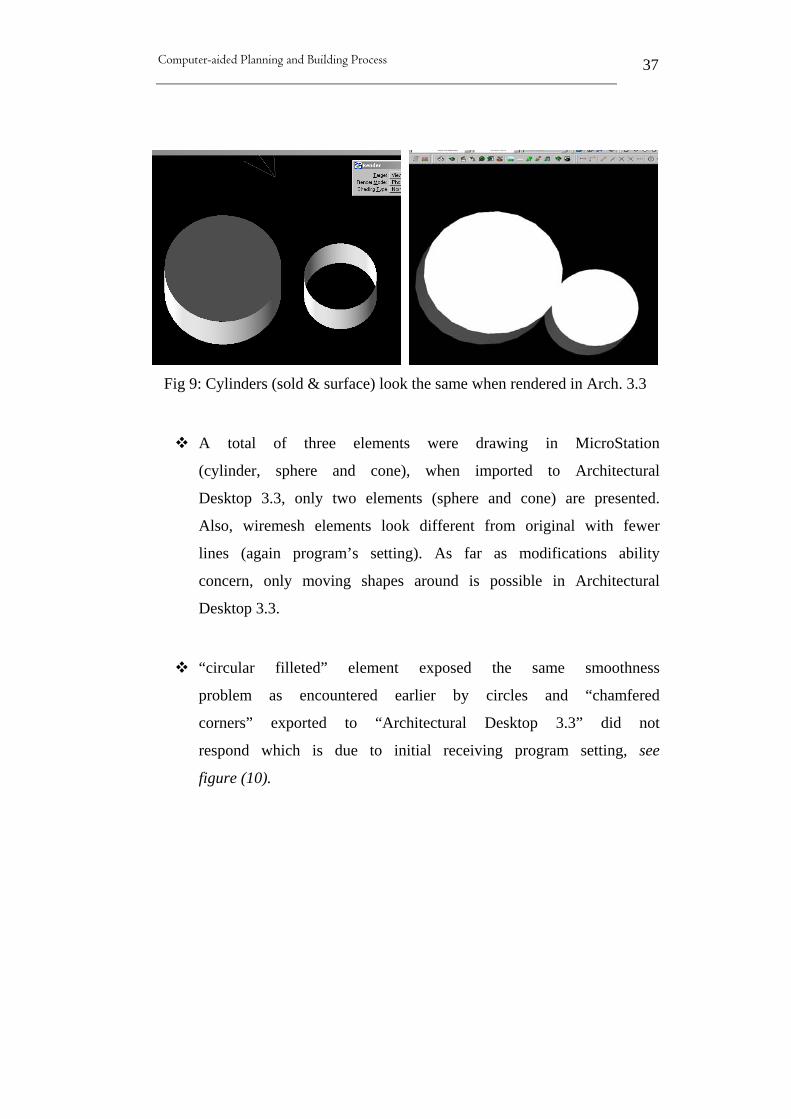
Fig 9: Cylinders (sold & surface) look the same when rendered in Arch. 3.3
A total of three elements were drawing in MicroStation
(cylinder, sphere and cone), when imported to Architectural
Desktop 3.3, only two elements (sphere and cone) are presented.
Also, wiremesh elements look different from original with fewer
lines (again program’s setting). As far as modifications ability
concern, only moving shapes around is possible in Architectural
Desktop 3.3.
“circular filleted” element exposed the same smoothness
problem as encountered earlier by circles and “chamfered
corners” exported to “Architectural Desktop 3.3” did not
respond which is due to initial receiving program setting, see
figure (10).

Computer-aided Planning and Building Process
38
Fig 10: “circular filleted” and “chamfered corners” differ in Arch. 3.3
“Solid slab” exported from “MicroStation” to “Architectural
Desktop 3.3” allow for different modifications abilities. Once
arrived at “Desktop”, the user can modify one point of the slab
without having to move the whole slab where originally,
modifying one point of the slab means enlarging or decreasing
the size of the whole slab as seen in figure (11). However,
exported “surface slab” acts in the same manner as in original
applications.

Computer-aided Planning and Building Process
39
Fig 11: Sold slab behaves differently in Arch. 3.3
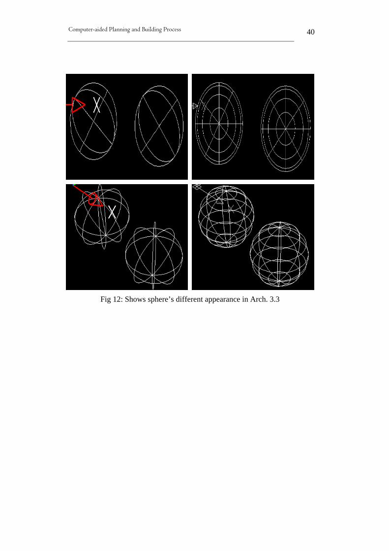
Software initial settings seem to appear in many other occasions
which cause some confusing during the sharing process.
Example is the “sphere” which also poses its own appearance
problems. It is represented differently as a 3D wiremesh object
which is illustrated by figure (12).
Computer-aided Planning and Building Process
40
Fig 12: Shows sphere’s different appearance in Arch. 3.3

Computer-aided Planning and Building Process
41
“Cones” drawing in “MicroStation” and exported to
“Architectural Desktop 3.3” are also suffered from 3D wiremesh
representation as direct results of initial software settings figure
(13).
Fig 13: Arch. 3.3 represents “Cones” wiremesh differently

Computer-aided Planning and Building Process
42
3.3.3 Exporting elements form Allplan 2004 to MicroStation V8
Once again, the issue of “license agreement” between “Allplan” and
“MicroStation” arises. This means elements exported form
“Nemetschek Allplan 2004” will be saved as “MicroStationV7”
format. However, in this case, “MicroStationV8” works around this
obstacle and recognizes the exportation process and poses two possible
solutions: 1) Upgrade the file to V8 format or 2) open the file as read-
only (keep as V7 format). Therefore, for the purpose of sharing data
between the two applications, the first option is chosen.
Nemetschek Allplan Elements names in
German
Status of exported
elements
Element identified as (in
MS)
2D Elements
Basic Tools Basisfunktionen
Line Linie Ok, exact measurements Line
Construction Line Konstruktionslinie Ok Construction line
Polygonzug Ok Line
Point Punkt Ok Shape
Rectangle Rechteck Ok, exact measurements Individual lines
Circle Kreis Ok Circle
General Circle Kreis allgemein Ok Circle
N-Eck Ok, measurements not
accurate Individual lines
Ellipse Ellipse Ok Arc
Spline Spline Not ok Curve
Single point Einzelpunkt Ok with extra
information
Shared Cell (lines &
circles)
Free hand line Freihandlinie Ok Complex chain, line
Hatching Schraffur Ok, association lost Shape
Pattern Muster Ok Shape
Extended
construction Erweiterte Konstruktion
Symbol
Symbolpunkt Not ok Text
Spline with Spline mit Ok with appearance Curve

Computer-aided Planning and Building Process
43
connection
Anschlussrichtung differences
Chamfer Fasen Ok Line
Axis Achsraster Ok, acts as individual
elements Line & text
Polar axis Polarachsraster Ok, but considered as
separate elements Line, Arc & text
Text Text
Horizontal Text Text horizontal Ok Text
Vertical Text Text vertikal Ok Text
Angled Text Text unter Winkel Ok Text
Numbering Text Text mit Nummerierung Ok Text
Bar code Barcode Ok Shape & Text
Dimension Lines Maßlinie
Horizontal Dim. Maßlinie horizontal Ok. association lost Dimension Line
Vertical Dim. Maßlinie vertical Ok association lost Dimension Line
Angled line
Dimension Maßlinie im Winkel Ok association lost Dimension Line
Dimension lines in
black form Maßlinie in Blockform Ok association lost Dimension Line
Automatic
dimensioning Automatikbemaßung
Ok association lost &
accuracy Dimension Line
Curved dimension Kurvenbemaßung Ok Line
Axis dimension Achsbemaßung Ok Line & Text
Angle dimension Winkelbemaßung Ok Arc & Text
3D Elements
Roof and planes
flyout
Gable/Hip Roof Dachhaut Ok Individual lines
Skylight Dachflächenfenster Ok Shared cell (solids)
Architecture
Components flyout
Straight Wall Gerade Wand Ok Solid
Rectangular Walls
Rechteckiger Wandzug Ok Solid
Curved Walls Kreis-Wand Ok Solid
Circular Walls Kreis-Wand um Mittelpunkt Ok Solid
Polygonal Walls
Inscribed N-Eck-Wand (halb) Ok Solid
Polygonal Walls
Circumscribed N-Eck-Wand (ganz) Ok Solid
Spline-Based Walls Spline-Wand Ok Solid
Brace Stütze Ok, but different
modifications Solid

Computer-aided Planning and Building Process
44
Slab Decke Ok, but different
modifications Solid (shapes)
Beam, suspender
beam Unterzug, Überzug
Ok, but modified
differently Solid (shapes)
Chimney Schornstein Ok, but different
modifications Solid (shapes)
Architecture
Openings flyout
Door Tür Ok Shared cell (solids)
Window Fenster Ok Shared cell (solids)
Corner Window Eckfenster Ok Shared cell (solids)
Öffnungsmodellierer Ok Shared cell (solids)
Rooms flyout
Room Raum Ok Solid (shapes)
Floor Geschoss Ok Solid (shapes)
Stairs flyout
Straight stairs Gerade Treppe Ok, but extra
information Solid (shapes)
Half coiled stairs Halbgewendelte Treppe Same as above Solid (shapes)
Simple quarter stairs Einfach viertelgewendelte
treppe Same as above Solid (shapes)
Double quarter stairs Zweifach viertelgewendelte
treppe Same as above Solid (shapes)
Coiled stairs Wendelte Treppe Same as above Solid (shapes)
U-Type Stair Halbpodesttreppe Same as above Solid (shapes)
A four-valley landing
stairs Einviertalpodest Treppe Same as above Solid (shapes)
Two-four-valley
landing stairs Zweiviertalpodest Treppe Same as above Solid (shapes)
Table (3) Exporting elements from Nemetschek Allplan to MicroStation
According to table (2), it is noticeable that exportation from
“Nemetschek Allplan” to “MicroStation V8” works more smoothly
than the other way around. However, previously encountered issues
and problems seem to occur in this case again. Elements association is
a common issue occurring during sharing of information between
“MicroStationV8” and “Allplan 2004”.

Computer-aided Planning and Building Process
45
Fig 14: Illustrates lost of dimension association in Arch. 3.3
Figure (14) illustrates the lost of dimension association by “Architectural
Desktop” because the dimension did not react with the change in length,
whereas on the left hand side (in Allplan), the dimension decreasing in
accordance with the change in element’s length.
“Polygonal Walls” looks ok after arriving at MicroStation, but lines
measurements are not accurate and differ from original measurements.
“Spline” shared between “Allplan 2004” to “MicroStationV8” appears
different in smoothness and shape as seen figure (15).
Fig 15: Illustrates the difference in Spline appearance

Computer-aided Planning and Building Process
46
All “single points” elements exported to MicroStation seem to
have extra information (numbers) included which they are not
present in original software (Allplan) as shown in figure (16).
These numbers drawing on top of each element on the left hand
side figure are not part of the original elements and therefore
consider as extra information that again may have to do with
initial program settings.
Fig 16: Shows extra information on top of each element in Ms
A “freehand” line was exported to “MicroStation” without
noticeable changes, however once modified, this “freehand” line
acts as many segments and not one piece as in the original
application.
“Symbols” created in “Allplan 2004” are not possible to be
shared with “MicroStationV8”, instead some numbers appears to
represent these symbols as shown in figure (17).

Computer-aided Planning and Building Process
47
Fig 17: Symbols from Allplan are represented by numbers
“Spline with connection” exported to “MicroStation” has
different shape appearance as illustrated in figure (18).
Fig 18: Spline with connection appeared differently in MicroStation
“Barcode” seems to act like individual elements when exported
to “MicroStation”, even though it is originally one element.
Also, the overall appearance is different as shown in figure (19).
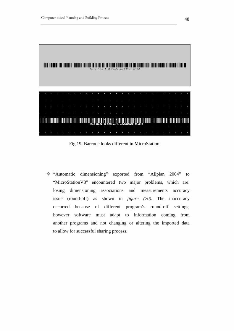
Computer-aided Planning and Building Process
48
Fig 19: Barcode looks different in MicroStation
“Automatic dimensioning” exported from “Allplan 2004” to
“MicroStationV8” encountered two major problems, which are:
losing dimensioning associations and measurements accuracy
issue (round-off) as shown in figure (20). The inaccuracy
occurred because of different program’s round-off settings;
however software must adapt to information coming from
another programs and not changing or altering the imported data
to allow for successful sharing process.
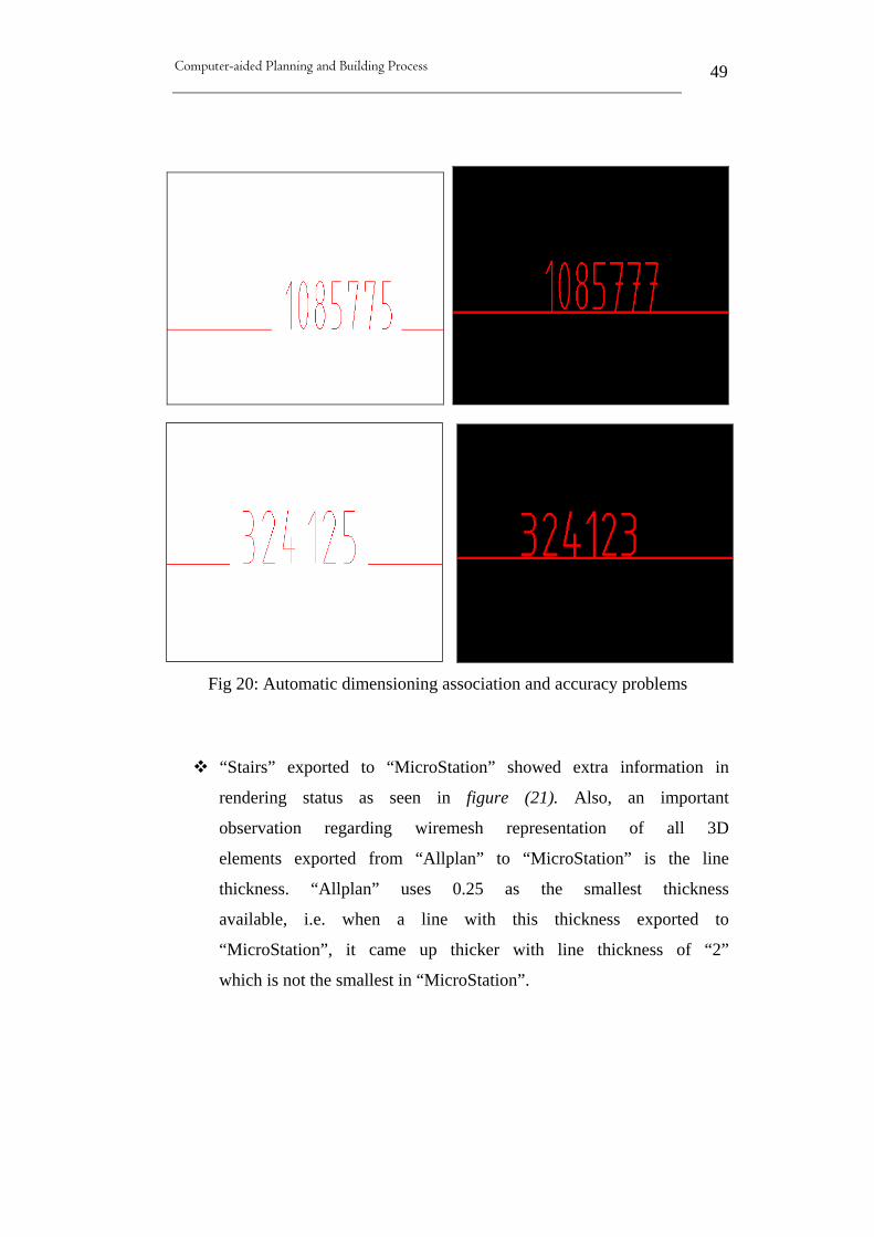
Computer-aided Planning and Building Process
49
Fig 20: Automatic dimensioning association and accuracy problems
“Stairs” exported to “MicroStation” showed extra information in
rendering status as seen in figure (21). Also, an important
observation regarding wiremesh representation of all 3D
elements exported from “Allplan” to “MicroStation” is the line
thickness. “Allplan” uses 0.25 as the smallest thickness
available, i.e. when a line with this thickness exported to
“MicroStation”, it came up thicker with line thickness of “2”
which is not the smallest in “MicroStation”.

Computer-aided Planning and Building Process
50
Fig 21: Stairs exported from Allplan to MS included hiding information
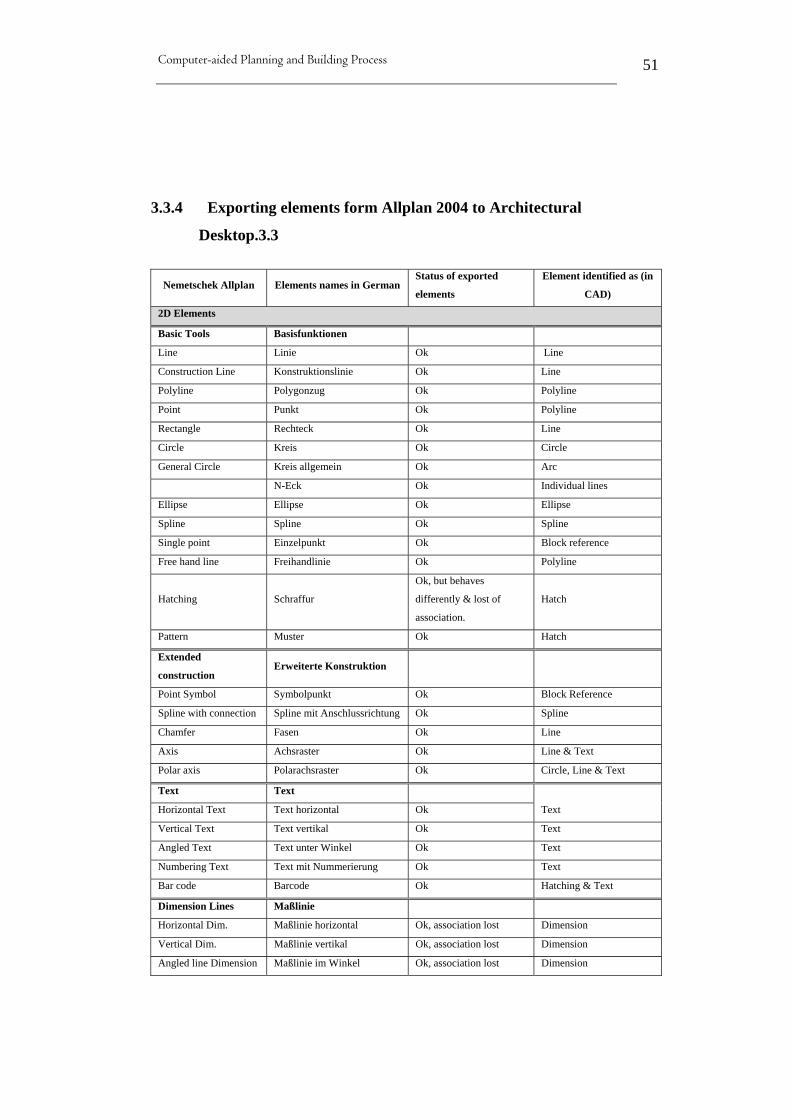
Computer-aided Planning and Building Process
51
3.3.4 Exporting elements form Allplan 2004 to Architectural
Desktop.3.3
Nemetschek Allplan Elements names in German Status of exported
elements
Element identified as (in
CAD)
2D Elements
Basic Tools Basisfunktionen
Line Linie Ok Line
Construction Line Konstruktionslinie Ok Line
Polyline Polygonzug Ok Polyline
Point Punkt Ok Polyline
Rectangle Rechteck Ok Line
Circle Kreis Ok Circle
General Circle Kreis allgemein Ok Arc
N-Eck Ok Individual lines
Ellipse Ellipse Ok Ellipse
Spline Spline Ok Spline
Single point Einzelpunkt Ok Block reference
Free hand line Freihandlinie Ok Polyline
Hatching Schraffur
Ok, but behaves
differently & lost of
association.
Hatch
Pattern Muster Ok Hatch
Extended
construction Erweiterte Konstruktion
Point Symbol Symbolpunkt Ok Block Reference
Spline with connection Spline mit Anschlussrichtung Ok Spline
Chamfer Fasen Ok Line
Axis Achsraster Ok Line & Text
Polar axis Polarachsraster Ok Circle, Line & Text
Text Text
Horizontal Text Text horizontal Ok Text
Vertical Text Text vertikal Ok Text
Angled Text Text unter Winkel Ok Text
Numbering Text Text mit Nummerierung Ok Text
Bar code Barcode Ok Hatching & Text
Dimension Lines Maßlinie
Horizontal Dim. Maßlinie horizontal Ok, association lost Dimension
Vertical Dim. Maßlinie vertikal Ok, association lost Dimension
Angled line Dimension Maßlinie im Winkel Ok, association lost Dimension

Computer-aided Planning and Building Process
52
Dimension lines in
black form Maßlinie in Blockform Ok, association lost Dimension
Automatic
dimensioning Automatikbemaßung Ok Dimension
Curved dimension Kurvenbemaßung Ok Block Reference
Axis dimension Achsbemaßung Ok Block Reference
Angle dimension Winkelbemaßung Ok Block Reference & Text
3D Elements
Roof and planes
flyout
Gable/Hip Roof Dachhaut Ok Block Reference
Skylight Dachflächenfenster Ok Block Reference
Architecture
Components flyout
Straight Wall Gerade Wand Ok Solid
Rectangular Walls Rechteckiger Wandzug Ok Solid
Curved Walls Kreis-Wand Ok Solid
Circulated Wall around
middle point Kreis-Wand um Mittelpunkt Ok Block Reference
Polygonal Walls
Inscribed N-Eck-Wand (halb) Ok Solid
Polygonal Walls
Circumscribed N-Eck-Wand (ganz) Ok Solid
Spline-Based Walls Spline-Wand Ok Solid
Brace Stütze Ok, but some difference
at bottom Solid
Slab Decke Ok Solid
Beam, suspender beam Unterzug, Überzug Ok Solid
Chimney Schornstein Ok Block Reference
Architecture
Openings flyout
Door Tür Ok Arc & line
Window Fenster Ok Block Reference
Corner Window Eckfenster Ok Block Reference
Rooms flyout
Room Raum Ok, extra information Solid & Text
Floor Geschoss Ok, extra information Solid & Text
Stairs flyout
Straight stairs Gerade Treppe Ok, but with extra
information Solid
Half coiled stairs Halbgewendelte Treppe Ok, but with extra
information Solid
Simply quarter stairs Einfach viertelgewendelte Ok, but with extra Solid

Computer-aided Planning and Building Process
53
treppe information
Doubly quarter stairs Zweifach viertelgewendelte
treppe
Ok, but with extra
information Solid
Coiled stairs Wendelte Treppe Ok, but with extra
information Individual lines
U-Type Stair Halbpodesttreppe Ok, but with extra
information Solid
A four-valley landing
stairs Einviertalpodest Treppe
Ok, but with extra
information Solid
Two-four-valley
landing stairs Zweiviertalpodest Treppe
Ok, but with extra
information Solid
Stairs with arbitrary
sketch
Treppe mit beliebigem
Grundriss
Ok, but with extra
information Solid
Table (4) Exporting elements from Nemetschek Allplan to Arch.3.3
Table (4) illustrates the level of accuracy maintained during the sharing
process between “Architectural Desktop 3.3” and “Nemetschek Allplan
2004” in term of measurements and identification of elements as well
as exact coordination. However, some of the common exchanging
problems encountered previously, such as hatching and dimensioning
associations are also present in this case which are explained as follow:
Hatched elements exported from “Allplan” to “Autodesk”
behave totally differently in term of modifications, in addition to
loosing original association.
Although “wall unit” exported from “Allplan” to “Autodesk
Architectural” has maintain its exact original measurements and
rendered ok (figure 22), it is presented differently in “wiremesh”
as seen in figure (23).
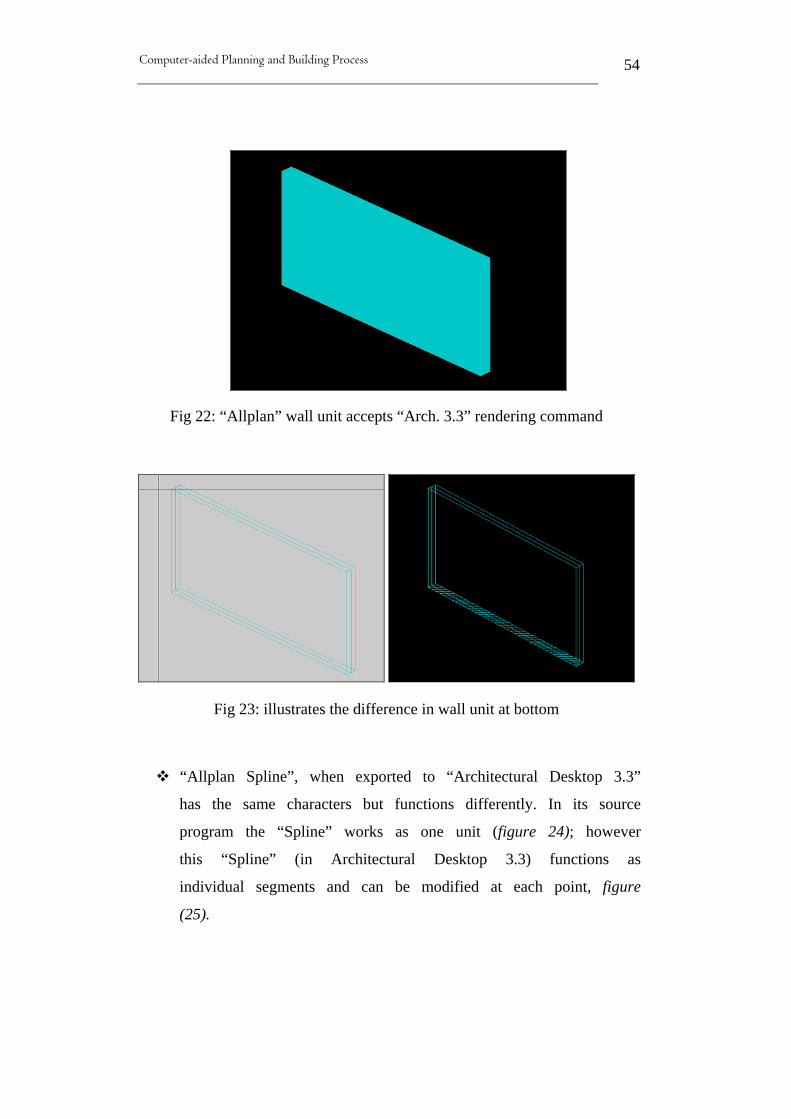
Computer-aided Planning and Building Process
54
Fig 22: “Allplan” wall unit accepts “Arch. 3.3” rendering command
Fig 23: illustrates the difference in wall unit at bottom
“Allplan Spline”, when exported to “Architectural Desktop 3.3”
has the same characters but functions differently. In its source
program the “Spline” works as one unit (figure 24); however
this “Spline” (in Architectural Desktop 3.3) functions as
individual segments and can be modified at each point, figure
(25).

Computer-aided Planning and Building Process
55
Fig 24: Nemetschek Allplan “Spline” works as one unit
Fig 25: Arch. 3.3 “Spline” behaves as separate elements and modified
differently
Different presentation of “Braces” exported to “Architectural
Desktop 3.3” is encountered during the sharing process which is
similar to the previous case of “wall unit”, see figure (26).

Computer-aided Planning and Building Process
56
Fig 26: Shows the difference in braces at bottom
“Room” exported from “Allplan” to “Desktop 3.3” preserve
their original looks and features; however the room size seems
to appear in all view by “Desktop” producing unnecessary
information, figure (27).
Fig 27: Extra information introduced in all views in “Arch.3.3”

Computer-aided Planning and Building Process
57
All type of “stairs” exported from “Allplan” to “Desktop 3.3” initiate
the same issue as previous discussed by the preceding element (room)
as well as some falls wiremesh presentation especially with the “coiled”
(round) stairs and “U-type” stairs, as seen in figure (28).
Fig 28: Extra data and falls “wiremesh” presentation of elements.

Computer-aided Planning and Building Process
58
3.3.5 Exporting elements form Architectural Desktop 3.3 to
MicroStation V8
Sharing design data between “Architectural Desktop 3.3” and
“MicroStationV8” runs smoothly allow for better compatibility compared with
the preceding situations which clearly shown by table (6). However, some
viewing problems related to rendering and initial software settings need some
attention as well as some other worth mentioning issues which are presented,
explained in more details and illustrated by figures hereafter.
Architectural
Desktop 3.3
Elements names in
German
Status of exported
elements
Element identified as
(in MS)
2D Elements
Line Linie Ok, exact measurements &
coordinates. Line
Construction line Konstruktionslinie Ok Line
Multi-line Multilinie Ok Multi-line
Polyline Polylinie Ok, but without thickness. Line
Polygon Polygon Ok Shape
Rectangle Reckteck Ok Shape
Arc Bogen Ok Arc
Circle Kreis Ok Ellipse
Spline Spline Ok Interpolation curve
Ellipse Ellipse Ok Ellipse
Ellipse Arc Ellipse Bogen Arc
Hatching (with & without
association) Schraffur Ok Hatching
Cross hatching (with & without
association) Ok Hatching
Text Text Ok Text
Dimensions (Vertical & Horiz) Ok Dimension lines
3D Elements
3D face 3D-Fläche Ok Smart solid
Cylinder Zylinder Ok Smart solid
Cuboids Quader Ok Smart solid
Wedge Keil Ok Smart solid
Cone Kegel Ok Smart solid
Sphere Kugel Ok Smart solid
Ring Torus Ok Smart solid
Table (5) Exporting elements from Arch.3.3 to MicroStation V8

Computer-aided Planning and Building Process
59
Although “MicroStation” has recognized hatching elements
imported form “Architectural Desktop 3.3” with exact names as
stated there (i.e. hatching ANS 137), a major concern was posed
by “sphere”. Once in “MicroStation” this “sphere” though
looked similar, it did not rendered as shown by figure (29).
Fig 29: Sphere imported from Arch.3.3 to MS in different stages
The previous “wiremesh” viewing problems exist also when
exporting different “3D shape” to “MicroStation”. These shapes
are view differently as MicroStation 3D wiremesh objects and
did not allow for rendering (figure 30).
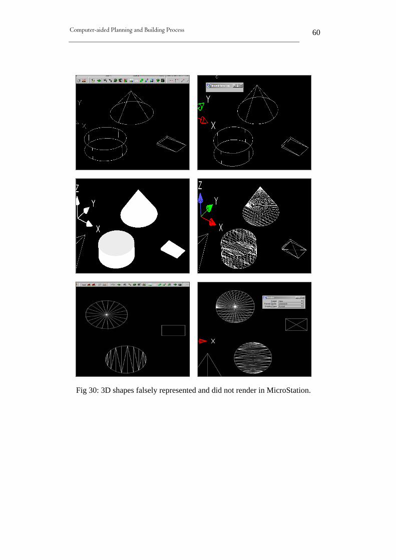
Computer-aided Planning and Building Process
60
Fig 30: 3D shapes falsely represented and did not render in MicroStation.

Computer-aided Planning and Building Process
61
3.3.6 Exporting elements form Arch. 3.3 to Nemetschek Allplan 2004
Although, “Nemetschek Allplan 2004” seems to recognize and identify
elements imported form “Architectural Desktop 3.3” in a good manner,
there is always the issue of loosing dimensioning association as well as
modification ability of some elements such as “Spline” and “Ellipse”.
Also, dimensioning text modification proofs to be an issue as shown by
table (6) and associated attached figures.
Architectural
Desktop 3.3
Elements names
in German
Status of exported
elements
Element identified as (in
Nemetschek Allplan)
2D Elements
Line Linie Ok 3D Line
Construction line Konstruktionslinie Ok 3D line
Multi-line Multilinie Ok 3D Line
Polyline Polylinie Ok 3D Line
Polygon Polygon Ok 3D Line
Rectangle Reckteck Ok 3D Line
Arc Bogen Ok, modification is
different 3D Line
Circle Kreis Ok Circle
Spline Spline Ok Spline
Ellipse Ellipse Ok Ellipse
Ellipse Arc Ellipse Bogen Ok 3D Line
Hatching Schraffur Not Ok, association lost Hatching
Text Text Ok Text
Dimensions (Vertical & Horiz) Ok Dimensions lines
3D Elements
Solid Solid Ok Individual 3D lines
3D face 3D-Fläche Ok Individual 3D lines
Cylinder (solid) Zylinder Not possible
Cuboids Quader Ok Individual 3D lines
Wedge(surface) Keil (Flächen) Ok Individual 3D lines
Cone Kegel Ok Individual 3D lines
Sphere (surface) Kugel (Flächen) Ok, no rendering Individual 3D lines
Ring Torus Ok Individual 3D lines
Table (6) Exporting elements form Arch. 3.3 to Nemetschek Allplan
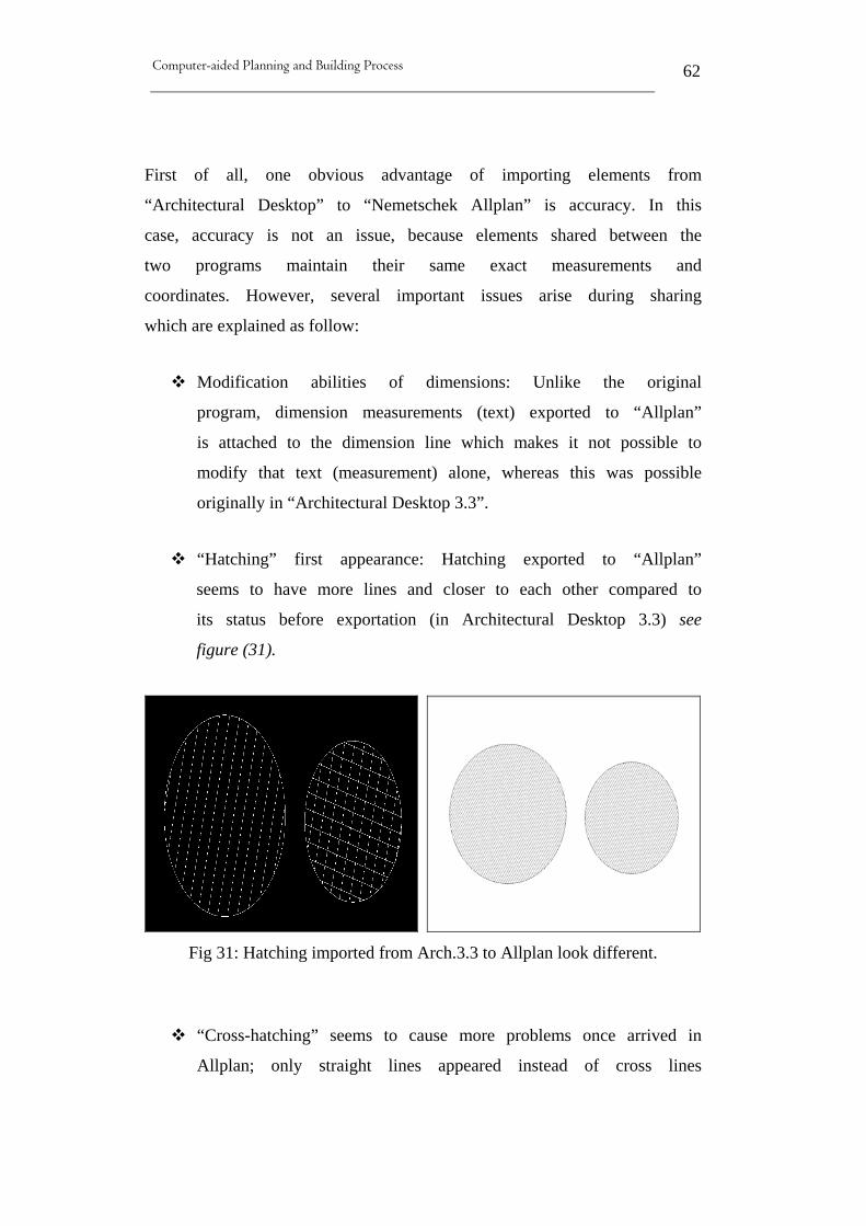
Computer-aided Planning and Building Process
62
First of all, one obvious advantage of importing elements from
“Architectural Desktop” to “Nemetschek Allplan” is accuracy. In this
case, accuracy is not an issue, because elements shared between the
two programs maintain their same exact measurements and
coordinates. However, several important issues arise during sharing
which are explained as follow:
Modification abilities of dimensions: Unlike the original
program, dimension measurements (text) exported to “Allplan”
is attached to the dimension line which makes it not possible to
modify that text (measurement) alone, whereas this was possible
originally in “Architectural Desktop 3.3”.
“Hatching” first appearance: Hatching exported to “Allplan”
seems to have more lines and closer to each other compared to
its status before exportation (in Architectural Desktop 3.3) see
figure (31).
Fig 31: Hatching imported from Arch.3.3 to Allplan look different.
“Cross-hatching” seems to cause more problems once arrived in
Allplan; only straight lines appeared instead of cross lines

Computer-aided Planning and Building Process
63
originally created in Architectural. Also, lost of dimensioning
association acknowledge in both hatching, figure (32).
Fig 32: Illustrates the loss of hatching association.
The “Sphere” animates like original but cannot be modified in
the same way.
The “Architectural Desktop 3.3 Spline” when imported to
“Nemetschek Allplan” works as one unit, and allows for
different modifications abilities as shown in figure (33).
Fig 33: Arch. 3.3 Spline is modified differently in Nemetschek Allplan

Computer-aided Planning and Building Process
64
Also the same modification ability issue occurred with “Ellipse”
imported form “Architectural Desktop 3.3” to “Allplan”.
Importing 3D elements to “Allplan” is only possible if they are
surface element, 3D solid elements are not possible to be
imported from “Architectural Desktop 3.3” to “Allplan”. In
addition, surface elements cannot be rendered in “Allplan” as
shown in figure (34).
Fig 34: “Architectural Desktop” 3D elements cannot be rendered by “Allplan”

Computer-aided Planning and Building Process
65
3.4 Conclusion and discussion
This chapter has examined and investigated data exchange ability
between three proposed CAD applications which are available at Berlin
University of Technology (TU Berlin) which are: 1) Bentley’s
MicroStation V8 (Architecture); 2) Nemetschek Allplan 2004; and 3)
Autodesk Architectural Desktop 3.3 (Deutsch version). The aim was to
explore these proposed CAD applications currently used by the AEC
industry and examine their compatibility and interoperability. The
emphasis was to examine each of the proposed applications ability to
share design data with the others, by means of exporting and importing
single elements between them.
Optimistically, observation throughout this chapter indicates that there
is a sense of communication between these applications, especially
how fast and easy data were delivered from one application to another
without the use of third-party tools. Most importantly, vendors and
software producing bodies are considering compatibility and allowing
for data exchange abilities with other related products which clearly
illustrated throughout this chapter.
However, although in many occasions the exchanged elements have
passed smoothly and function exactly in the same way after sharing,
some elements pose serious problems that hinder the sharing ability
and full compatibility between applications which are used by the same
people for the same purposes in the same industry. These problems
which occurred during this process and their related sequences are
explained as follow:-
• Loosing of elements associations: the most repeated problem
found in this research is losing associations in both hatching and

Computer-aided Planning and Building Process
66
dimensioning. Generally, most types of dimensions and hatches
exchanged between proposed applications have lost their
association abilities as illustrated throughout this chapter. This
could be very damaging to the accuracy and quality of design
and consequently required manual editing of certain dimensions.
• 3D wiremesh representation: this is a major issue which
occurred in many occasions when exchanging 3D objects.
Although due to initial software settings and could be solved
easily, the user should be made aware of this or proposed
software should be able to adapt to other software conditions.
• Element modification abilities: some elements once shared with
other software, allow for a little or no modification at all.
• Elements identifications: how element being identified by other
software is also an issue. It is well noticeable throughout this
process and clearly shown in associated tables that many
elements when exported to another program were falsely
identified by the receiving application which means losing
original property of elements.
This process has examined exchanging data between proposed CAD
applications using single elements and not a complete file to pin point
exact possible problems. Yet in practice, a complete design file would
be transformed to another application in which some problems could
not be easily identified. In addition, the AEC industry consists of
several key players who generate large amounts of data that need to be
shared among project’s team members (architects, engineers,
contractors, etc.) during its lifecycle. To give an example, the National
Institute of Standards and Technology (NIST) in 2004 estimated $15.6
billion per year is the cost of lack of interoperability in the U.S. capital

Computer-aided Planning and Building Process
67
facilities market- including commercial, institutional and industrial-
facilities [1].
With the widespread of CAD tools among companies and educational
institutes, in addition to companies and firms going global, it is vital to
acknowledge these problems and communication obstacles early prior
to marketing in order to avoid damaging the already fragmented
industry. Thus, these obstacles and hindrances should be considered in
any future development by both vendors and industry practitioners.
Also, the AEC industry should work closely with software inventors to
lay down their requirements and expectations in order to gain
maximum advantages of digitized era.
Finally, the investigations process throughout this chapter proves that
unless standardizations of AEC industry software applications become
part of future developments by both vendors and the AEC industry as a
whole, this technology is limited and cannot be employed to its
fullness. However, education institutions and industry are making
efforts in this direction and improvements can already be noticed.
Hence, this process took place from the period of October 2004 until
May 2005, and softwares are usually developing and updating fast. So,
helpfully these issues are already addressed in the newer versions.


Computer-aided Planning and Building Process
69
4 VIRTUAL CITY EXAMPLE (VRCE)
4.1 Introduction
From the beginning of urban planning, designers, decision-makers and
the general public have searched for innovative methods to visualize
the built environment prior to actual construction. This includes
colored maps and site plans, cardboard models and rich architectural
renderings. Yet, these methods failed to be a complete, effective
technique to visualize the past, present and future of a “place” to the
vast array of bodies involved in the planning process.
Recently, the affordability and decrease cost of real time virtual reality
both software and hardware, has made this technology more accessible
and encouraged urban planners to adopt it as a tool of visualization.
Mainly, due to large memory, processing and graphics power of
today’s hardware which makes modeling and visualizing of large-area
cities on computers feasible [84].
Thereby, virtual cities (sometimes called digital cities) emerged into
cyberspace which, are computer based models that have enough of the
qualities of real cities to give the user a real sense of being in an urban
place. A virtual city can also be composed of a road network that
provides the basic structure of the urban area and a large number of
buildings that are arranged in blocks [3].
Consequently, introducing VR technology throughout the urban
planning process enables users to navigate a virtual world safely and
experience the environment as it currently exists, how it could have
existed or as it might look in the future. Along the way, the user can
also experiment with different alternative such as replacing existing

Computer-aided Planning and Building Process
70
buildings with new developments and trees and foliage can be changed
to see the impact. In addition, this technology allows users to query the
available database to view information on buildings or places with the
simulation [6&7]. Also, the real estate sector can benefit from virtually
exploring a city by visualizing houses and objects within a 3D terrain
and support the corresponding marketing and management activities.
Simultaneously, the tourism sector is also to benefit from this
technology by promoting their region and service on the internet, with
links to further information such as hiking, ski and tourism areas as
well as hotel and restaurant locations.
There are currently thousands of Cities on the World-Wide Web
(WWW). New towns and cities are emerging in cyberspace,
constructed with digital bricks and mortar, which are being called
virtual cities, digital cities or cyber-cities. They are used for different
purposes such as shopping, relaxing and meeting friends. Because
cities layout is familiar aspect to most people, they are being used as an
interface symbol to information and services on the WWW [4].
Among the groups who are to benefit from virtual cities are:- those
interested in learning about the city in a fairly immediate way such as
tourists; and those with a commercial interests which include business
of all kinds; as well as professionals dealing with the city itself such as
architects, planners and engineers [5].
An example is the 3D development of the old town of Edinburgh
which is now well developed and integrated into the city planning
process. Nowadays, to obtain planning permission in this town, a CAD
model of the proposed development in the appropriate format must be
submitted to be dropped into the virtual landscape. Also, the University
of Bath has developed a 3D computer model of Bath which is been
used by city planners to test visual impact of a number of proposed

Computer-aided Planning and Building Process
71
developments in the city. In Berlin, the urban development and
architecture unit of ART+COM has created the CyberCity Berlin and
the Planwerk (a 3D masterplan of the city) using new media in town
planning resulting from previous research on communication in city
planning [6 & 7].
a b
c
d e
Fig 35: Examples of Virtual Cities on the WWW Sources: a: http://www.skyscrapercity.com/showthread.php?t=307963 b: http://bdcampbell.net/cities/Viewing.html C: http://www.vision.ee.ethz.ch/~pmueller/wiki/CityEngine/PaperCities e: http://www.focus.de/digital/internet/bildergalerie_did_14477.html f: http://www.stadtentwicklung.berlin.de/planen/stadtmodelle/

Computer-aided Planning and Building Process
72
4.2 Objective
Due to an agreement between Berlin University of Technology (TUB)
and Building and Housing Research Center (BHRC) in Iran to enlarge
and broaden their cooperation and establish collaboration on further
academic and research related development activities. TUB is now
involving and working cooperatively with BHRC to plan and develop
several projects in different chosen locations in Iran. One of these
projects is the planning and development of Hashtgerd New Town
which is the largest of the thirty currently planned Iranian New Towns.
Considering the availability and accessibility of data through this
agreement, Hashtgerd New Town 2D plans will be used to develop a
virtual city example (VRCE) to navigate and explore the town
virtually. Mainly to explore and visualize the VREC, using virtual
reality tools and methods now available for planners and decision-
makers of the AEC industry. However, the VRCE will benefit from
available 2D plan of the proposed 35 hectare project and a 2D image of
the rest of Hashtgerd New Town to develop the complete 2D plan of
the town. Then some proposed 3D models will be created and placed
on top of the 2D plan to mock up Hashtgerd New Town in a virtual
environment. The developed VRCE will consist of imaginary models
and some actual proposed buildings models which will be dropped in
the VRCE to experiment with different visualization tools and
techniques.
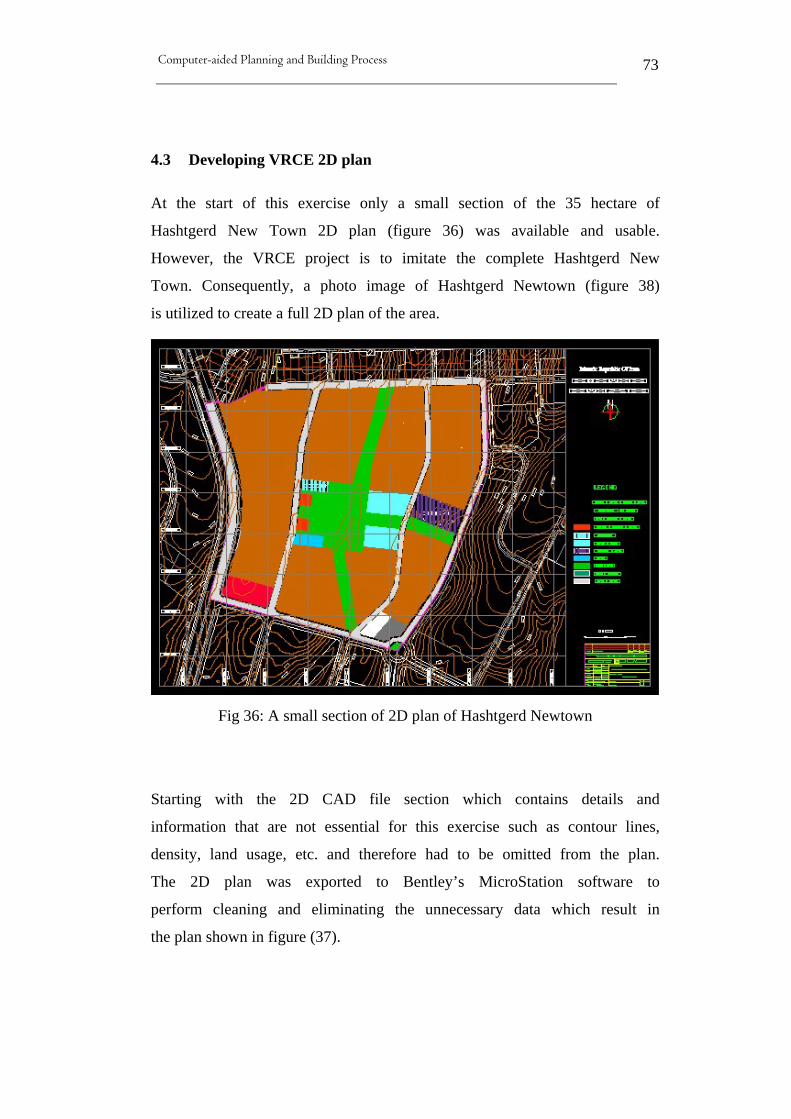
Computer-aided Planning and Building Process
73
4.3 Developing VRCE 2D plan
At the start of this exercise only a small section of the 35 hectare of
Hashtgerd New Town 2D plan (figure 36) was available and usable.
However, the VRCE project is to imitate the complete Hashtgerd New
Town. Consequently, a photo image of Hashtgerd Newtown (figure 38)
is utilized to create a full 2D plan of the area.
Fig 36: A small section of 2D plan of Hashtgerd Newtown
Starting with the 2D CAD file section which contains details and
information that are not essential for this exercise such as contour lines,
density, land usage, etc. and therefore had to be omitted from the plan.
The 2D plan was exported to Bentley’s MicroStation software to
perform cleaning and eliminating the unnecessary data which result in
the plan shown in figure (37).

Computer-aided Planning and Building Process
74
Fig 37: 2D section of Hashtgerd after eliminating extra information
To develop the rest of Hashtgerd New Town 2D plan, the photo image
(figure 38) was used to imitate the town and was connected with the
existing CAD section as close as possible. The final 2D plan of
Hashtgerd is shown in figure (39) which is developed using Bentley’s
MicroStation and will be used next in developing the VR city.
However, at this stage a 2D CAD plan of Hashtgerd (fig. 40) has being
obtained from the designer and can be used hereafter.

Computer-aided Planning and Building Process
75
Fig 38: A photo image of Hashtgerd Newtown

Computer-aided Planning and Building Process
76
Fig 39: the full developed 2D plan of the VRCE

Computer-aided Planning and Building Process
77
Fig 40: 2D CAD plan of the Hashtgerd New Town
4.4 Developing the VRCE Models
Once the VRCE full 2D plan is established, several 3D building
models are created to form the VR city. However, since the proposed
location (Hashtgerd New Town) is still under development, most 3D
models used here are imaginary buildings placed all over the 2D plan
to give the impression of a city-like feeling as well as some actual
proposed buildings models.
Using Bentley’s MicroStation, designing and inserting the 3D models
is achieved through several methods and approaches to illustrate

Computer-aided Planning and Building Process
78
different alternatives and explore proposed software capabilities. The
first method which represents a large number of models used to form
the VRCE is accomplished as MicroStation cells. This means each
model is designed separately and saved as a unique cell in order to be
inserted into the 2D plan in a specific location as required. The second
approach is the directly built models that are designed and placed
directly on top of the 2D plan which required less time and effort
compared to the previous approach. The third approach which is
relatively faster compared to the two previous methods, is achieved by
copying some of the existing models (cells and directly built) and place
them over the 2D plan as required.
However, all 3D models used to create the VRCE have been designed
as simple 3D boxes with no details (doors, windows or materials) to
minimize overall file size in order to be exported and illustrated by
different visualization tools and methods (figures 41&42).

Computer-aided Planning and Building Process
79
Fig 41: 3D models as placed to form the VRCE

Computer-aided Planning and Building Process
80
Fig 42: Simple 3D models developed differently to form VREC
After creating and placing all 3D models as required, the VRCE is
ready to be explored and examined by different visualization tools and
options. Three visualization tools have been determined for that
purpose which will be explained further next and they are:-
1. The CAVE
2. On Screen visualization
3. Google Earth Tools

Computer-aided Planning and Building Process
81
4.5 Visualization Tools and Methods
4.5.1 The CAVE
Viewing a large area such as the VRCE would usually require a
suitable environment with reasonable screen sizes which most offered
by the CAVE (Cave Automatic Virtual Environment). The CAVE is
also referred to by AGC [70] as electronic CAVES or (computer-aided
virtual environments), which was developed by the University of
Illinois in Chicago and introduced in 1992 at the SIGGRAPH (Special
Interest Group for Computer GRAPHics) conference. It is designed to
overcome some of the earlier VR systems limitation such as the
HMD’s and the BOOMS (TM) and to be used as a useful tool for
scientific visualization. The objective is to provide high resolution, a
large field of view, and a stable display that did not restrict the number
of viewers and would allow for multiple people to easily share the VR
experience [9]. It consists of several computers and a room constructed
of large screens on which the graphics are projected onto two to three
walls and/or the floor where multiple viewers can look at a simulated
image using a 3-D high-resolution audio and video environment. In
order to see the image in a 3D format, LCD stereo shutter glasses and
infrared emitter are used. The shutter glasses are used to ensure that
each eye sees only the image drawn for it. In fact, the 3D model that
appears on the walls is in accordance with the view point of the user
with the tethered electromagnetic glasses on. However, only one set of
glasses has the tethered on them, but the other viewers can still see the
3D models with the use of the shutter glasses without tethered [3& 85].
They only need to stay close to the user with the tethered glasses to

Computer-aided Planning and Building Process
82
have the same feeling. In addition, this system also offers
electromagnetic sensors on the wand which is the equivalent of a
computer mouse to interact with the scene.
a b
Fig 43: The CAVE (Cave Automatic Virtual Environment)
Sources: a: http://inkido.indiana.edu/a100/handouts/cave_out.html, b: http://www.evl.uic.edu/pape/CAVE/idesk/paper/
4.5.1.1 Loading the VRCE to the CAVE
Although the CAVE that is available at TU Berlin has the same
specification and equipments mentioned; it is being called Portal (copy
right issue). However, it is not a complete room for it has only three
walls (screens) and no screen on top (ceiling) as illustrated by figure
(44). Also, the Portal software (jReality) is under development and
increasingly steady with more functionality; however, no audio was
required for this exercise [55].
The VRCE file was saved as VRML (Virtual Reality Modeling
Language) world and then uploaded to the Portal system. With the
provided shutters (sun glass like) the user can experience true 3D
feelings. These shutters are equipped with a sensor that tries imitating
human eyes; the scene moves according to the viewer’s head

Computer-aided Planning and Building Process
83
movement. Also, the system provides “wand” (a mouse like
instrument) that allows for interaction abilities. The viewer can
interact, move the scene, zoom in and out and move the model as
required with help of the wand.
Fig 44: Screen shots of visit to the TU portal
4.5.1.2 Problems and issues observed during visualization
Some of the issues and problems experienced during this process are as
listed follows:
• 2D data omitted by VRML: since VRML represents 3D data, all
2D data included with the VRCE such as lines which
represented streets and properties did not import to the Portal.
This has affected the overall scene of the VRCE in which only
buildings models were shown without 2D data indicating roads

Computer-aided Planning and Building Process
84
or properties edges. To overcome this limitation, all 2D
elements that represent roads and properties edges were changed
to 3D objects by given them thicknesses and heights. On the
second attempt at the Portal after changing the 2D elements to
3D; the overall view of the VRCE looked better with roads and
properties edges present.
• Navigation and interaction: navigation and flying through the
VRCE was very slow and instable which is due to the large size
of the VRC file and the portal’s software which was still under
development at the time.
• Privilege over the use of shutters: not all shutters (glass) used by
viewers have sensors which is understandable. Only one user
has this privilege which gives him/her the control to direct the
model to his own eye directions.
• Mobility and cost of technology: the large size and high cost of
the CAVE prove to be the biggest challenge researchers are
facing. The CAVE is considerably expensive tool to own and its
huge size requires a big room and allow for no mobility. It
requires very expensive equipments, tools, occupies a large
space and cannot be used, for example, on a job site easily.
4.5.2 PC Screen Visualization (MicroStation)
On screen visualization is the most common and extensively used
method when dealing with 3D digital models. Since 3D models are
generally designed and created by computers, it is most logical and
quickest way to get first impression and briefing of the design is in the
same environment (computers).

Computer-aided Planning and Building Process
85
Therefore, the VRCE benefits from visualizing options and techniques
offered by “MicroStation” such as walk-throughs and fly-throughs
which are achieved on any computer screen. The on screen
visualization is achieved in “MicroStation” by different methods and
approaches. However, for the VRCE the walk-through is achieved by
specifying a certain path around and through the VRCE 3D models as
desired. Then, a fixed camera is set to follow the specified path to take
a series of shots of the models along that path in the desire directions
and angles. A total of 384 images were taking along the designated
path and were saved as *.jpg images (figure 45). These images were
then loaded to MicroStation’s video maker to compose a viewing video
which could be then saved in a different format offered by the program
(i.e.*.avi, *.wpg, *.epx, etc). However, for the VRCE the produced
video was saved as Windows AVI (*.avi) which is provided as screen
shots hereafter (figure 46).
Fig 45: A sample of the images created along the walkthrough path

Computer-aided Planning and Building Process
86
Fig 46: Showed snap shots of VRCE video
4.5.2.1 Advantages and disadvantages of onscreen visualization
Advantages:-
1. Mobility and availability: combining BIM software with a
laptop or personal computer offers a mobile visualization tool
that could be used conveniently almost whenever needed, such
as on the job site or in conferences, which is not possible in
many other visualization tools.
2. Relatively cheaper: in comparisons to other visualization tools
and equipments.
3. No need for extra interference equipment: such as VR glasses,
gloves or head mounted display.
Disadvantages:-
1. No surroundings (visual or sounds) is provided through the
visualization process.
2. The small screen is not adequate for a large group of audiences.

Computer-aided Planning and Building Process
87
3. It does not allow for immerse interaction for users as offered by
other visualization techniques as in the CAVE for example.
4. Hard and software requirements. Realistic photo rendering
usually required high-performance computers with high memory
which is usually costly and not always at hand.
4.5.3 Google Earth Tools
Google Earth is an application from Google Inc. that provides 3D
interface to view imagery from any location on Earth. Recently,
MicroStation was connected to Google Earth to enable viewers to
navigate 3D models in the context of rich geographic imagery. This
includes tools that enable users to publish complete 2D and 3D CAD
models along with geospatial data directly to the Google Earth format.
Additionally, this link between Google Earth and MicroStation allow
for the coordination of MicroStation Geo-Graphics data to be
automatically export to the correct locations in Google Earth.
Moreover, the rich environment of Google Earth which is serving as a
graphical navigation device for all project content and graphical
navigation will be more intuitive than a file structure. So, MicroStation
user can export complete 3D models with geospatially located 2D data
directly to the Google Earth tool.
“Bentley” claims, “MicroStation” is the first single-point solution to
publish geospatially located 2D and 3D models directly to the Google
Erath environment. By releasing a plug-in, MicroStation was able to
publish DGN and DWG files to the Google Earth environment. It
presents data to Google Earth as KML (Keyhole Markup Language)
documents and XML based data structure for creating and sharing
geographic data. In addition, exporting MicroStation geometry to KML

Computer-aided Planning and Building Process
88
maintains the “Reference File” and “Level” (layer) structure defined in
the model as well as saved views which are also saved as KML. This
enables users to selectively control the display of levels or reference
files within Google Earth environment. Moreover, Croser [8] indicated
that connection with Google Earth will include all the richness of the
“MicroStation” model content as follow:-
All raster reference files are exported to the Google Earth
service’s KML file.
All model levels are carried to KML file so Google Earth
users can easily switch part of model or desired levels on
and off.
All model saved views are also transferred to the KML
file which allow users to view pre-configured
perspectives in the model
4.5.3.1 Loading the VREC to Google Earth
The VRCE is exported to Google Earth as a free visualization tool to
navigate and view the city in its context of rich geographic imager. The
VREC was transferred to Google Earth as a KML which allows all 2D,
3D data and levels included with the file to be present in Google Earth
interface.
The exportation process is illustrated by figure (47) and involves the
following steps:-
1. First, creating a “placemark” in Google Earth at the required
location and saving it as a “KML” file.
2. Second, using the “Define Placemark Monument” in
MicroStation to define a monument point that matches the

Computer-aided Planning and Building Process
89
location of the placemark that was already defined in Google
Earth.
3. Thirdly, using the “Export Google Earth (KML) File” tool to
export the file to a Google Earth “KML” file
4. Once the MicroStation file exported, Google Earth is opened
automatically and it navigates to the location of the placemark
and file.
Fig 47: Illustrates the process of exporting the VRCE to Google Earth
Desktop
Web Services
MicroStation
Google Earth
KML Files

Computer-aided Planning and Building Process
90
However, the 2D plan of Hashtgerd was transferred along with 3D
Models to show the geometry and terrain of the site which is not (as of
this writing) shown by Google Earth. Usually, where terrains and
geometry (i.e. roads, properties and surroundings) of a certain location
are shown by Google Earth, there is no need to export 2D data with the
models, because the models could be easily and effectively placed in
their location. However, this is not the case here; the Hashtgerd
Newtown location is underdevelopment and Google Earth does not
show any terrains or geometry of that location as shown in figure (48).
Therefore, the 2D plan of Hashtgerd is dropped on that location to
compromise for that missing information as shown below in figure
(49).
Fig 48: Hashtgerd location as presented by Google Earth

Computer-aided Planning and Building Process
91
Fig 49: 2D plan of Hashtgerd as placed on Google Earth
Computer-aided Planning and Building Process
92
Once the 2D plan of the city is placed in its exact location in Google
Earth environment, the 3D models of the VRCE are exported to form
the VR city. The final VRCE could then be viewed in Google Earth as
shown by figure (50), allowing for navigations, walking through in
real-time and exploring the whole city. In fact, users appreciate the
richness, surrounding details and the experience offered by Google
Earth which adds more meanings to 3D visualization. Also, shown
along are some examples of more detailed models which are obtained
from a proposed office building model that is being introduced in the
next chapter.
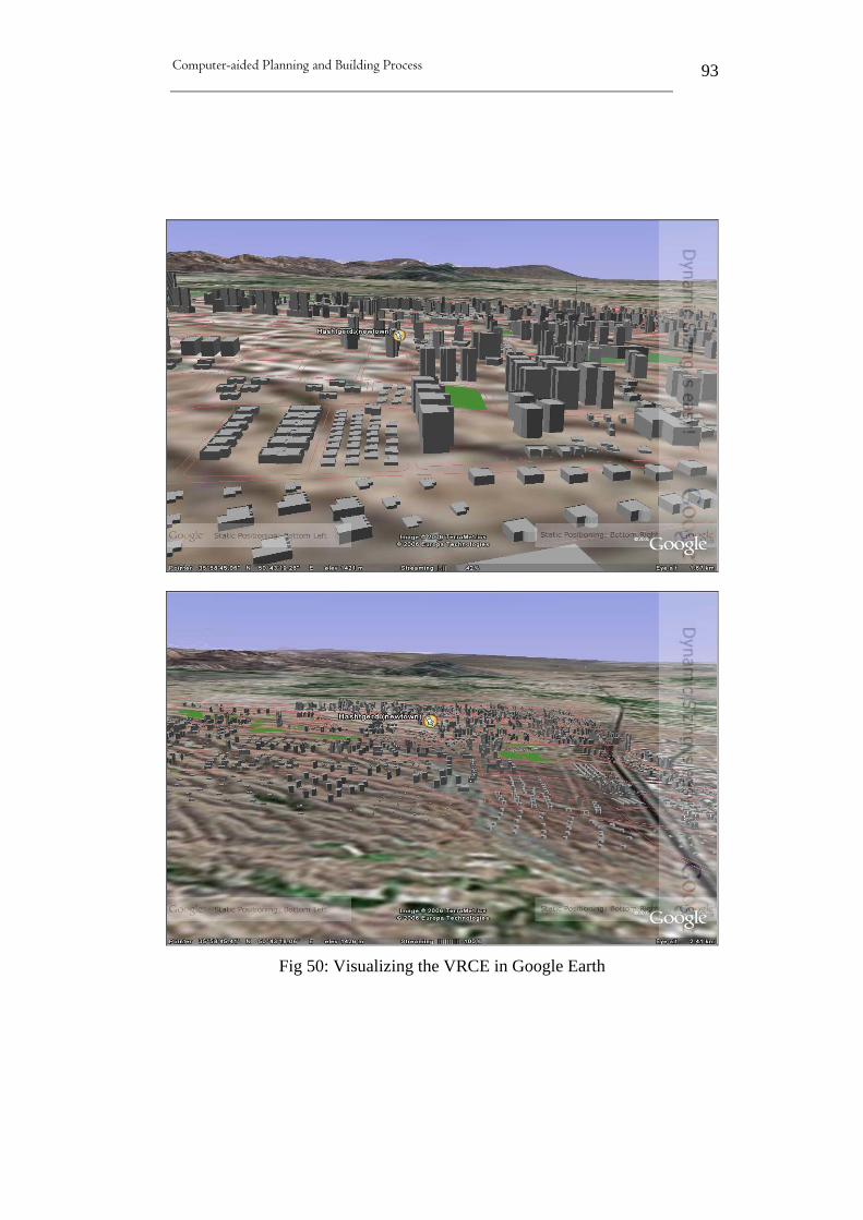
Computer-aided Planning and Building Process
93
Fig 50: Visualizing the VRCE in Google Earth

Computer-aided Planning and Building Process
94
Fig 51: Visualizing detailed VRCE Models by Google Earth

Computer-aided Planning and Building Process
95
4.5.3.2 Advantages and disadvantages of Google Earth visualization
Google Earth visualization method is generally rich in details and
allows users to view their models inside the Google Earth environment.
Its mapping service allow for broader AEC audience to gain a new
perspective on infrastructure projects, and to leverage DGN and DWG
data in an entirely different environment. It also, offers users an aerial
view of geometry and geography and provides richness, accuracy and
intuitive backdrop for AEC projects. Here the project can be viewed
and navigated in the context of rich geographic, imagery with
associated content such as surrounding buildings, transportation
systems, boundaries, bodies of water, etc. Also, the exported file can
contain links to more detailed data that users can review locally which
can be provided in a variety of formats including, Excel spreadsheets,
Word and PDF, just to name a few [8]. However, Google Earth
enabled exploring the VRCE beyond ordinary visualization tools and
methods. It gave the impression of real-like city and enabled viewers to
walk around and explore the city in the richness of Google Earth
environment. What is more, all data associated with the original file
such as layers, saved view, etc. (figure 52) are also provided by Google
Earth which allow users to switch layers on and off just like in a CAD
program. Other important advantages of using Google Earth tool are:-
1. Google Earth is free.
2. Google Earth can show information (model) in visually
fascinating way rather than in dry and academic way (reality like
impression).
3. It allows for very flexible navigations in which users are allowed
to achieve free range of motions and easy zooming.

Computer-aided Planning and Building Process
96
Fig 52: layers and associated data exported to Google earth
However, since this method is fairly new, there are still many obstacles
and hinderers that must be dealt with in the future. Some problems and
issues related to the process of visualizing VRCE in Google Earth are:-
1. Google Earth does not provide geographic imagery such as
buildings, transportation systems, boundaries, bodies of water to
all locations around the globe.
2. Models exported to Google Earth can only be smoothed rendered.
3. The geographic imagery of the existing buildings does not reflect
the true height of these building which makes the exported
model look awkward.
4. To play animation, users require third-party freeware.
Computer-aided Planning and Building Process
97
4.6 Conclusions
Virtual reality technology is being used in the planning of cities
and urban areas to assist planners and decision-makers better
understand the dynamic functioning of the city, just as it has
being used by other systems such as factories, airports and
shopping malls [86].
While modelling a large-area city poses a great challenge to
computer graphics, researchers and developers in this field are
mainly focused on developing methods and solutions to cope
with the high functional and visual complexity of large-scale
cities. What is more is the generating of the 3D city itself
including urban areas (buildings), transportation networks,
surrounding environment, etc. which is coming rather
cumbersome to designers. There are many approaches and
systems that aim to model existing cities including the use of
aerial imagery and remote sensing techniques to be able to
generate the layout of a large-scale city based on 2D-input
data. However, the effort of developing this VRCE was made
very simple which involves designing simple 3D models of
imaginary buildings including some actual proposed buildings.
The aim was to demonstrate the significant benefits that could
be realized by planners and decision-makers during planning
process. It has also illustrated that virtual cities are an
appropriate beneficial technology enabling engineers and
decision-makers to view and navigate future residential or
commercial development prior to construction. In addition,
there are considerable benefits using VR cities when planning
including resolve many problems or conflictions early in the
design process which leads to better design and improve

Computer-aided Planning and Building Process
98
overall time scheduling and meet project budget. However, the
primary aim of this VRCE was also to investigate different VR
tools and techniques that are available for use by participants of
the AEC industry. Three different visualization approaches
have been chosen (due to availability and affordability) to
explore and illustrate different tools and alternatives available.
While each tool has represented its own benefits and
limitations, it is the use of these tools and their functionality to
blame for a major portion of the encountered problems and
limitations as explained throughout this chapter. However, next
chapter will deal with a new emerging technology that
originated from VR which is Building Information Technology
(BIM).
Computer-aided Planning and Building Process
99
5 Building Information Modeling (BIM)
5.1 Background
For thousands of years mankind have been interested in building
construction projects. However, construction projects are typically too
large for any one individual to tackle alone. Therefore, from early on,
human began to think about ways to develop communications tools and
skills to achieve projects. In addition, building projects are often very
large and complex to plan, design and maintain which required many
specialist persons with a great variety of skills and interests to
cooperate in a common task. Ideally, since the ultimate goal of a
construction project will normally reflect the need and wishes of the
owner (an individual, a group of persons such as company or
organization), the construction project team members need to related to
the project and assist the owner to achieve the desire goals and
business plan. Also, construction team members need to harmonize and
agree to the owner’s goals which require collaboration between all
team members to achieve the eventual success of the building team [2].
In the beginning, there were drafting boards, T-square, rules and
pencils. However, in the early 1980s, architectural firms started
adopting computer-aided design (CAD) software. The aim is to support
drafting automation very effectively and with little effort. Within a few
years a large amount of construction documents and shop drawings
were plotted from computers instead of being manually drafted on
board. By the end of the decade, firms that didn’t make the switch
found it hard and costly to catch up. During the 1990s, 3D CAD

Computer-aided Planning and Building Process
100
drawings evolved from the 2D CAD drawings to create 3D-views of
the design and more advanced tools enabled engineers to design
directly in 3-dimensions using virtual models. Soon became evident,
that CAD advantages are well established and proven, with efficiencies
in drawing reuse, organization, revisions, quality and consistency, etc.
Although CAD originally emerged to automate the task of drafting, one
starts to think of it as more than just an electronic pencil and paper. In
fact, in order to achieve a certain level of consistency, this technology
requires a great level of effort.
Next, object-oriented CAD systems (OOCAD) evolved which replaced
the 2D symbols with building elements (objects) that capable of
representing the behavior of common building elements. OOCAD aims
to simulate building components in a CAD-based environment,
focusing on the 3D geometry of the building as well as producing 2D
document form the 3D geometry and extracting object data from the
building components to provide quantity information and object
properties [49&83].
Recently, the effort into making CAD products to be a complete
repository for the storage, visualization, coordination, manipulation
and extraction of relevant building information lead to Building
Information Model (BIM) which is a single 3D model most commonly
located within the CAD environment. In fact, BIM is the latest
generation of OOCAD systems in which all building smart objects are
stored in a single “project database” or “virtual building” that captures
everything about that building. This is the newly emerged solution to
ensure collaboration and communication between different project’s
stakeholders at different phases of the design through the life-cycle of a
facility. In addition, the use of BIM as a designing tool may help in
realizing the team’s project goals and improve collaborations,
communication and information consistency among all team members.

Computer-aided Planning and Building Process
101
It would allow project participant to work on a single model where the
entire data for a building could be stored, managed, coordinated,
visualized, dissected and extracted. Most importantly, the model is not
a collection of lines, but rather a collection of electronic objects that
have relationship with other element in the model and know how they
look and where they belong in that model [10]. However, BIM
technology is not a direct replacement of CAD systems rather it is a
natural progression from it. These issues including the concept of BIM
technology benefit gains and barriers as well as related experiences and
examples will be the subject of this chapter.
5.2 Objective
Using building information technology as a tool in AEC industry to
generate building abstractions such as plans, sections, elevation,
details, and schedules is the subject of this chapter. Mainly, this chapter
will discuss the basic concept of Building Information Model (BIM),
barriers, advantages and disadvantages, issues, related work. In
addition, to exploring some successes projects and provide some
valuable case studies. Finally, a BIM system for a proposed office
building in Iran will be developed.
5.3 What is BIM?
The term BIM was first introduced by Autodesk in 2002, which is an
emerging new technology with the potential to allow engineers and
designers significantly improve the speed, cost, and quality of facility
planning, design, construction, operation, and maintenance of their

Computer-aided Planning and Building Process
102
design [20]. BIM is also defined by the National Institute of Building
Sciences as:
A digital representation of physical and functional characteristics
of a facility. As such it serves as a shared knowledge resource for
information about a facility forming a reliable basis for decisions
during its lifecycle from inception on ward [21].
However, BIM has many great potentials and benefits and it has being
defined differently by different people in various sources. It is a new
promising approach to the design, analysis and documentation of
facilities. The main aspect of BIM circles around information
management of a design process of a facility throughout its entire
lifecycle from early design stages through construction administration
and even into facilities management. Information includes all the
design inputs such as: number of windows, the cost of materials, the
size of heating and cooling equipment, etc. This information which is
captured in a digital model can then be presented as coordinated
documents, be shared across multi disciplines, and serve as a
centralized design management tool [11].
Autodesk REVIT [22] defines BIM as an innovative new approach to
building design, construction, and management that was introduced by
Autodesk in 2002. It allows the constant and instant availability of a
design scope, cost and schedule in high quality and fully coordinated
format. Although, BIM is considered as an approach rather than a
technology, it’s supported to varying levels by different technologies.
Also, Huw Roberts, Bentley Systems’ global marketing director,
stated: BIM is not just software but a methodology of practice. In other
words, BIM means all project data is stored in one location which
eliminates inconsistency and data overlap that may lead to expensive
construction errors. This insures that every participant is working with
Computer-aided Planning and Building Process
103
the same exact information as everyone else in the project and changes
are made to objects only once. Handling project documentation in this
way reduces communication problems that slow down projects and
increase costs as well as, early findings of errors and inconsistency that
typically discovered only in the field when engineers working with
different set of drawings bump into each other [23].
Faulkner [12] identifies BIM as a completely integrated 3D model that
allows users to define, detect and avoid clashes in a virtual world in
which interferences are eliminated before construction ever begins.
BIM is also considered as an approach to building design, construction,
and management supporting the continuous and immediate availability
of high quality, reliable, and coordinated information. He
acknowledged that “a building information model is the ultimate
compilation of construction and design information, housed in a
database and graphically represented”. BIM functions in the way that
interferences and clashes are discovered early, before impacting the
final cost of a building. Utilizing specific software, clashes and
interferences are found on computer rather on the job site. In fact, BIM
technology dose not only impact those in the design and construction
fields, it also stands to benefit owners as well, especially, sophisticated
facility owners who already realizing the benefits of BIM.
In another interpretation by Smith and Edgar [13&17], BIM is a digital
representation of the physical and functional characteristics of a
facility. It offers a shared knowledge resource for information about a
facility forming a database for decisions making during its life-cycle
from inception onward. The concept of this technique is to build a
building virtually, before building it physically in order to solve
problems and interferences early in the design process. The model
should be completed considering everything related to the building
before construction whereby all conflicts or clashes between building

Computer-aided Planning and Building Process
104
systems have been worked out prior to physically constructing it. In
addition, it allows for participants to join in the development of the
virtual building, for example the fabricators will provide the
connection details building elements, as well as each participant will do
their same job, simply more rapidly in a more collaborative
environment. However, some people mistakenly define BIM principle
as only 3D modeling and visualization tool. This definition is limited,
since the concept of BIM is to be able to access all significant graphic
and non-graphic information about a facility as an integrated resource.
Laasonen and Karlakari [14] among others refer to BIM as a file or
database containing information about the concepts of construction,
such as spaces and building elements which include wall panels,
columns, doors, etc. Also, See [15] suggested that BIM should be
thought as the building industry’s application of Product Information
Modeling (PIM) concept where the product is a building. It can also be
thought of as a database of the building project.
However, Erger [16] argues that the definition of BIM remains a bit
unclear because it is an evolving concept, although it allows more than
just producing conceptual 3D models. The main aspect of BIM is the
“I” in the middle “information” which is the foundation of BIM. BIM
aims to develop a single project database that contains all project data,
both graphical and non-graphical including all architecture, structural,
electrical and mechanical systems information. By having all
associated data in a single, continuously updated database makes it
easier to manage and integrate all aspects of the project during the
design stage. In fact, BIM adds additional dimensions onto existing 3D
CAD techniques by attaching information to elements in the virtual
building. Indeed, using BIM technique has extended beyond collision
detection to focus on more functions such as real-time cost estimating.
When linked to cost data program, project’s budget can be tracked as

Computer-aided Planning and Building Process
105
the design evolves. It is also possible to link BIM database to outside
information resources, such as manufacturer specifications. He also
added that BIM has been qualified as the design tool of the 21st century
as well as the biggest thing since sliced CAD. Experts declared that this
technology enables users to create well detailed 3D models that prevent
guesswork out of the design intent and construction. Also, facility
owners prefer BIM since it provides better visualization of the
completed project and offer more documentation for continued
building operation and maintenance. It also offers easy management
and shared representation of physical and functional data that define
buildings through their life cycles. For that, BIM is increasingly seen
throughout the public and private real estate and construction sectors as
a way to control cost and performance problems associated with
inaccurate and incomplete communications [19].
DeStefano [18] adds, BIM may look like a CAD drawing but in reality
it is something else. With BIM, the computer realize what is being
drawing and what each line represent for example, unlike CAD
systems where lines does not mean much, in BIM building elements
can have attributes in which a line representing a beam correspond to a
beam of a certain size and material and it may also include analysis
data of that beam. What is more, BIM is a 3D parametric model of the
building which means a revision of an element in the model will only
need to occur once and the all views and details in the model are
automatically updated. This eliminates the possibility of errors
associated with inconsistency and uncoordinated drawings.

Computer-aided Planning and Building Process
106
5.4 Benefits of employing BIM
It is beyond the scope of this research to cover all benefits and
drawbacks associated with this technology; however the most
encountered aspects will be addressed. Yet, shifting to BIM process
promises many unthinkable advantages, thus BIM ultimate benefits are
still emerging in the market and will radically change the way building
are designed and constructed. In fact, the construction industry and its
activities are shifting and architects are stepping up to the challenge.
The shift is from traditional 2D abstractions to on-demand simulations
of building performance, usage, and cost. This is no more fantasy but a
practical reality. Now a day, all project participants are sharing a single
database in which architecture, structure, mechanical, infrastructure,
and construction are tied together and able to coordinate in ways never
before possible. Also, the digital model can now be sent directly to
fabrication machines to eliminate the need for traditional shop
drawings as well as energy analysis can be done at the outset of design,
and estimating construction costs are becoming more predictable and
reliable. Also working in a model-base framework ensures that any
change in any view will transmit to all other views of the model. This
framework environment guarantees as elements are shifted in plan,
they changed in elevation and section as well as removing a door from
the model will simultaneously gets removed from all views, and the
door schedule is updated. This enhances document delivery system
enables extraordinary control over the quality and coordination of the
document set [11].
However, architecture and construction have been developed for a long
time now. Thus, the great number of participants involved in the
planning and construction of a project makes communication and

Computer-aided Planning and Building Process
107
coordination a complex process to deal with. Traditional construction
methods are fragmented and lack the sense of reliability, especially
when dealing with large projects. For instant, looking through a project
documentations to find information about a particular aspect would be
disasters due to lack of consistency of documents. Most times
construction project documents failed to agree and match one another
because a tradesman might have one set of drawings, while the
architect may be using another set, at a different revision level. This
guarantee will not happen in the building information model since all
documents and views are produced form a single source when needed.
The BIM is an intelligent three-dimensional model that is the core of
the system. All parties involved in the project have access to the same
data, at the same level of updating. Better still, the knowledge and
familiarity about the facility grows as the project progresses in
consistency and the virtual building expand to become better
representation of the building itself over time. Moreover, actual
construction documents can be produced from the model when
required on screen or as hard-copy form. Also, architects and engineers
can involved and elaborate on concurrent design process, certain that
the model always reflects the latest decisions and everyone sees the
same information. This also applies to contractors and tradespeople
who can be certain that latest accurate documents are always available
earlier than with traditional methods for take-offs for early estimates
[23].
Additionally, working with a single 3D model during a project offers
several significant advantages, many of which have already been
proven in practice. However, most obvious is early identification and
avoidance of problems through interference checking and visual
verification. A single 3D model from which each discipline can extract
information needed make for more efficient process, eliminate

Computer-aided Planning and Building Process
108
duplication of work, less copies of identical information and less
chance for miscommunication of intent [10]. Also, since the best
means of understanding the construction environment is through
visualization, BIM provides engineers with a 3D environment that
echoes real live construction which means clearer communication of
building design compared to traditionally used 2D drawings. Indeed, a
fully formed BIM linked to supporting building data offers the
capability for downstream use of building information for users beyond
the initial AEC participants.
Also, the merge of this new BIM technology allows architects and
designers to experiment with alternative design solutions and scenarios
to optimize the expected cost. Equally important, is to derive ideas and
new ways of maintaining the facility while reducing its lifecycle costs.
Thus, BIM supports the potential of a design team to execute longer
term return on investment analyses more accurately and far more
quickly by providing architects and designers with information
required upfront to make informed short and long term cost decisions.
It also enables designers to swap materials of certain elements of their
design (cladding or window) and the model will illustrate how these
changes affect the overall cost of the project. More effectively,
architects utilizing BIM technology can perform value engineering for
clients either by reducing material costs or by illustrating that material
choice will have a positive impact on total cost of ownership due to
operating costs. In addition, architects and designers can keep track of
economic variables such as interest and inflation rates, energy costs,
and the potential for rising materials costs in the future. With BIM
designers can execute these economic and design trade-offs upfront,
eliminating repetitive design changes as drawings get passed to project
participant. This reduces expensive changes during the construction
phase of the facility [25].
Computer-aided Planning and Building Process
109
DeStefano [18] added, BIM allows all participants of the design team
to contribute and add information to a common model. Thereby, each
participant adding layers of information to the same model in which is
managed by one of the team members. Consequently, working on the
same model will improve clash detections and identifies any collisions
early in the process. Also, case studies illustrated that steel fabricators
have been able to concentrate on reviewing the shop drawings and
viewing more difficult areas in more depth rather than wasting time on
re-inputting tedious data such as member sizes [10].
However, the early detection of construction collisions and
interferences, enhanced with the use of computer generated simulation,
the automatic generation of bill of materials and the designing of
complicated models on computer have obvious benefits in the design,
construction and facilities management of buildings as follows:
5.4.1 Benefits during the design phase
The 3D model developed by the BIM software is designed directly
rather than being generated from multiple 2D views which can then be
used to visualize the project at any stage of the designing process
ensuring consistency in all views [49]. From previous experiences, it
has been demonstrated and proven that maintaining and distributing
data among a network of stakeholders in the construction industry
results in data duplications and confusions. This is due to participants
involved in the process such as architects, structural engineers and
others independently maintaining their own information in the most
convenient format for their separate activities. This trigger a disaster
when it comes to design changes which in most cases, a management
system can identifies them but they must be re-applied manually

Computer-aided Planning and Building Process
110
because there is no automated option possible due to separate system
being used by participants. BIM overcomes this issue by offering an
approach in which all project participants contribute and work on a
common model.
What is more, the widespread of “design and build” is encouraging the
adoption of BIM and making it more attractive to companies and
contractors to incur cost now in order to save cost later. Yet, BIM
technology promises real cost and time savings due to reduced costs of
communication and coordination as the project passes through each
phase of the construction lifecycle [24].
Demchak among others [11] are also optimistic about the adoption of
BIM into the construction industry, which offers designers and builders
better tools to create, control, and display information. In additions,
they listed the followings advantages users can expect to gain using
BIM during the design phase of a project:
• Visualization enhances understanding the building and its space
and allow for showing different design options.
• Integrated design documents reduce errors and improve
documents consistency.
• Interference checking identifies conflicts between architectural,
structural, and mechanical elements in 3D and eliminate costly
errors on site.
• Automated up-to-date schedules of building components.
• Quantity take-offs of materials offers better predictability and
planning.
• Easy to explore sustainable strategies and alternatives.

Computer-aided Planning and Building Process
111
Clearly BIM provides architects and designers with the ability to
realize design changes quickly, generate convincing 3D renderings and
accurate construction documents, in addition to building lifecycle
ability. Along the way, BIM can generate order forms, schedules, bill
of quantities and more … providing contractors with accurate
quantities to accelerate their pricing scheme [26]. It gives also
structural firms and structural engineers an integrated modeling
environment for analysis and documentation, so that the structural
design and documentation are always coordinated, consistent, and
complete. Simultaneously, the ability to deliver existing architectural
digital design data and share the structural BIM among architects and
structural engineers further coordinates the building design and
documentation in which benefit all parties involved in the design,
construction, and operation of a building [12]. In addition, BIM is
capable of embedding information relating to materials, lighting,
energy, access, evacuation, ventilation, etc. which offer the opportunity
to use this model for analysis and simulation, providing better
information for architectural and design optimization decisions [29].
Obviously, having all project data in a single, updatable database
would make data and accuracy easier to manage and integrate all
aspects of the project during the design phase. What is more, project
owners view BIM as a promise to offer a high quality project as well as
time and cost savings. The ability to visualize the facility as a 3D
model helps owners to gain a better understanding, early in the design
process of the look of their final project. Also, any design issues or
interference can be addressed early; and any revisions made during the
design process can be updated within the database as necessary and
changes are automatically integrated throughout the process [16].
Henry Tyler, CIO of Fairfax, V said in an article by Yoders [27]: BIM
is a powerful tool because of its 3D designs capabilities to allow for
Computer-aided Planning and Building Process
112
almost every decision regarding building’s construction to be made
early in the design stage of the project. In addition, using digital
models during the design phase enable the design team to resolve
systems-integration problems during design, long before the project
goes into construction in which potential cost savings is realized [28].
5.4.2 Benefits during the construction phase
Although difficult to thoroughly measure and compare the productivity
of different construction projects, the evidence suggests strongly that
benefit of using BIM technology on the productivity of personnel
during the construction phase is increased [29]. Using BIM should
provide contractors and construction process participants during the
construction phase more complete as well as more effective
representation of design intent. This means, there is a greater chance
that the finished project will look like the completed 3D model [16].
Williams [30] emphasized that BIM can provide material and
equipment take-offs which means more accurate construction bidding,
reduced change orders due to design errors and field coordination, and
ultimately a building that better meets the owner project requirements.
In addition, BIM provides the greatest opportunity for improving
construction documents generation since CAD. Utilizing BIM as a
modeling versus drafting tool forces designers to think more about how
the building will be constructed in addition, automated coordination
tools within BIM can detected clash and interference between building
elements.
If properly managed and applied, BIM have the potential to be a
powerful tool for the structural engineers and it enables contractors to
build an exact replica of the electronic model of their facility.
Computer-aided Planning and Building Process
113
DeStefano [18] believes that there is also the opportunity to import a
BIM directly into a fabricator’s shop drawing applications in which
this data can be also used to drive automated fabricating machinery and
element paper shop drawings. Fabricators will reduce waste because
optimization of tasks such as cutting of sheet metal and pipe can
benefit from all scrap pieces. Smith [13] added, construction sites are
now safer because more building items will be pre-assembled off site
and delivered to the construction site minimizing on-site trades
activity. This means less waste on-site and products will be delivered
when need and not stockpiled on site.
Moreover, it has been reported by the AIA (American Institute of
Architects) conference in 2004 that a staggering $100B is the cost of
fixing and administrating construction “errors”. Driven by cases where
something done on-site differ from the intended specifications as
planned. This extra cost occurs not only through the unnecessary
rework on-site but also through extra time spent consolidating,
checking, questioning and interpreting the multiple pieces of
information generated from the specifications. Improving
communications between participant and the way the design is
translated into the physical construction phase could reduce or
eliminated this extra cost. BIM has the motive and capabilities to
deliver these savings [24]. It also enables construction mangers to
determine how trouble-free the facility can be constructed according to
specific design data. In addition, by linking the facility model to
preliminary schedules they can evaluate the overall constructability of
the design using simulation of alternative construction sequences.

Computer-aided Planning and Building Process
114
5.4.3 Benefits during the management phase
Given that BIM is a relatively new initiative in the construction
industry, there has, as yet, been little opportunity for owners and
managers to quantify benefits in the operations and maintenance phase.
Nevertheless, BIM technique offers key pieces of data about the
facility that can be used to analyze building performance. For example,
the designer could generate data from the model for use in calculating a
wide range of performance, such as heat/loss gain, day lighting effects,
air flow, emergency routs, structural performance and financial
feasibility which means creating a closer linkage between analysis and
design process [31]. Huel [32] claims that benefit of BIM go far
beyond design and construction where information forms the BIM
model has many potential uses in the life cycle of a facility. In fact, the
true value of BIM becomes apparent once used in operating and
maintaining the facility. More impotently, the model is a living entity
which includes all important data related to the life cycle of the facility.
Hence, a BIM utilizes digital technology to establish a computable
representation of all the physical and functional elements of a facility
and its related life cycle information and is intended to be a repository
of information for facility management for maintaining the life cycle of
a facility [19]. Harris [34] also believes that BIM powers go beyond
improvement of the local construction industry to be a critical juncture
for the industry domestically and internationally. Concerning today’s
critical industry issues such as energy conservation, environmental
stewardship, and sustainability, BIM techniques allows for a common
tool to dramatically improve designers and decision-makers response
to these crucial issues. He argues that BIM will be most successful
when information created during design and construction is regularly
shared with operators and sustainers of facilities. This will allow for
Computer-aided Planning and Building Process
115
data obtained by facility managers to be used throughout facilities long
lifecycles and eliminate the re-gathering of information.
Brucker [88] emphasizes that BIM is not just a three-dimensional
computer aided design model; it’s a process of generating and
managing facility data throughout the life cycle, from planning and
design, operations and maintenance, through removal and smart
recycling. The aim is to capture data suitable to each participant at
each step of the life-cycle, making their jobs easier, more efficient, and
producing better quality buildings. In addition, Smith [13] implies that
once the BIM of a facility is completed, it will be delivered to the
operator and sustainer of the facility and any modifications or
improvements will be recorded in the model. Thereby, the model is the
reliable source and will be utilized throughout the life of the facility to
plan and tackle any modifications and changes. By serving as a
repository for the complete life-cycle of a facility, BIM has the
potential to be the best possible basis for facility management.
Additionally, facility owners and managers are to gain the greatest
benefits from using BIM including: better design scheme, more
efficient construction, better control over processes, and the best
possible documentation for facility management [23]. They could also
benefit more by having well detailed models and schematics available
for ongoing operation, maintenance and future renovation of their
facility [16].
Moreover, BIM promotes cooperation by different stakeholders at
different phases of the life-cycle of a facility. This cooperation includes
inserting, extracting, updating or modifying information in the BIM to
support and reflect the roles of that stakeholder. Still, an important
objective of BIM is to improve business functioning so that collection,
use and maintenance of facility information is a part of doing business
by the authoritative source and not a separate activity [17].
Computer-aided Planning and Building Process
116
Certainly, updatable models of existing buildings are an investment in
information, in which maintenance of buildings effectively achieved.
However, to ensure investment retains its value an effective and well-
organized method for maintaining the information is required. Thus,
the overall aim is that better information increases the effectiveness of
use and maintenance of buildings. This merely depends on the status of
the information which should be up to date and sufficient as well as
information concerning the physical appearance of the buildings must
also be available [14].
Morover, Matta among others [33] stated that in the future BIM will
allow designers and constructors to work collaboratively throughout
the project delivery process, focusing on creativity and problem
solving, while computers do the tedious tasks of counting and
checking. In addition, facilities owners and managers stand to benefit
the most, through the use of the facility model and its embedded
knowledge throughout the 30 to 50 year facility lifecycle.
5.4.4 Benefits during Construction handover
Once a project is completed, the facility manager obtains many
“bankers’ boxes” full of information about their facility at construction
handover. This information is provided in paper format indicating all
necessary data regarding the facility such as equipment warranties,
replacement parts lists, building system operating instructions,
maintenance job plants, and fixed asset lists. Whoever uses the
information provided must pay to have this information entered into
the relevant data systems and sometimes facility maintenance
contractors are paid to survey the existing building to capture as-built
conditions. This means the facility’s owner pays for the same thing

Computer-aided Planning and Building Process
117
twice; once for the construction contractor to finish the documents at
the end of the project and again for the maintenance contractor survey.
East [35] interviewed public agencies as they confirmed at least one
public building owner has paid three times for construction information
handover. Firstly, project data is included in the cost of the completing
of the design and construction of the project; secondly, the owner paid
to have the construction documents re-collected at the end of the
construction phase and provided in paper boxes along with the keys to
the new facility manager; thirdly, since the paper boxes data cannot be
loaded directly to maintenance management software, the owner has to
pay for the operations contractor to survey the building again to
identify existing equipment locations, serial numbers, etc.
In additions, there are several problems associated with the current
construction handover procedure as follow:-
1. At the end of the project, construction contractors are ordered to
recreate and gather information that has been developed by
others which will induce errors.
2. Receiving the information at the end of the construction contract
results in less than satisfactory deliverables, many of which are
available earlier in the project, but not captured.
3. Inadequate exchange format preventing others from effectively
using the data provided. Also, documents provided as paper
format is often loss, cannot be easily updated and take up a large
amount of space.
4. The information provided regarding replaced equipment is often
insufficient to ensure compliance with design intent.
However, the new trend in construction information handover is BIM
in combination with other tools. One attempt is using COBIE

Computer-aided Planning and Building Process
118
(Construction Operations Building Information Exchange) which will
be explained further later in the section “BIM issues and
standardizations”. The COBIE is designed to work with BIM to
exchange IFC-based facility management data that simplifies the work
required to capture and record project handover data [91].
Another attempt using BIM to capturing data during design and
construction of a project, and then handing it over to facility operators
is provided by Brucker [88]. This attempt uses the Ifc Model Based
Operation and Maintenance of Buildings (IFC-mBomb) which aims to
bridge the gap between the design/construction of a building and
handover to those who will be responsible for operation and
maintenance. The intent is to develop a method that will allow a
seamless flow of information to pass from design and construction to
operation and maintenance - and then decommissioning and demolition
if need be. In fact, this system allows a wealth of data on a building to
be assembled, exchanged, stored, re-used and updated during the life of
a building. It ensures that when a building project is handed over to the
client, a seamless flow of information, stored fully and accurately in a
model server, will contribute to the efficient management of the
building.

Computer-aided Planning and Building Process
119
Fig 53: The “IFC-mBomb” project model diagram
Courtesy of: http://cig.bre.co.uk/iai_uk/iai_projects/ifc-mbomb/
5.4.5 More BIM benefits
Additional BIM benefits have been provided by Industry Directions
[24] which could be realized by the AEC industry as follow:-
1. Improved client communications: better visualization tool
offers by BIM technology and the ability to illustrate the
different phases and options of the facility, speed client
approvals of a design.
2. Improve efficiency of the architects involved: BIM allows
architects to spend their time thinking about design, rather than
maintaining a drawing database.
3. Reduced time on drawing preparation and revision: since the
model maintains relationships between design information and
final construction documentation, any changes can be updated

Computer-aided Planning and Building Process
120
automatic and any needs for revision can also be notified by the
system.
4. Increased collaboration within the design team: collaboration
among project participants is a critical factor to risk reduction. It
is based on the concept that all design team members’ work on
the same project with the same goals, in support of the owner’s
interests. Thus, the main idea of BIM is the opportunity for
architects and engineers disciplines to work on the same model,
allowing for early recognition of problems, and less surprises
on-site.
5. Reduced time to produce material takeoffs: unlike current
practices which use 2D drawing to achieve takeoffs, BIM can
generate takeoffs automatically, delivering a quicker turnaround,
more accurate estimates, and streamlining procurement.
6. Reduced costs through increased standardization and
modular-off-site construction: catalogues linked to the project
specifications can lead architects and engineers to use standard
options. Discrete units, such as washrooms, may be
commissioned off-site ensuring that they will fit first time.
7. Improved efficiency of construction: simulation of the
construction can improve the construction planning process.
This ensures feasibility of the planned sequence and achieves the
best use of all resources. Using photogrammetric techniques to
assess as-built status against plan facilitates problem solving.
Moreover, Hartmann and Fischer [36] in the 2007 AISC-ACCL
eConstruction Roundtalble Event Repot, address the current situation
of the AEC industry regarding the use and implementation of BIM in
Computer-aided Planning and Building Process
121
which a number of projects utilizing BIM has been achieved. Many of
these projects are able to realize these benefits:
• Higher productivity in the field gain of 20-30%.
• Less requests for Information (RFI) and Change Orders (CO) by
a factor of ten or more.
• Higher engagement and buy-in of all important stakeholders.
• More design options from more perspectives with the same
budget and time schedule than traditional methods.
Also listed by Wyatt [67] the following BIM benefits:-
1. Changes updated automatically: individuals within a single office
and multi disciplines firms are able to automatically track
changes. For example, an engineer imports BIM from the
architects and changes the size of a certain structural member for
strength criteria, when the BIM is sent back to the architect, the
changes are automatically updated in the architect’s BIM.
2. Saving time during design phase: only one model is need for a
project, instead of several models in each design discipline.
3. Simplicity of tracking revisions and changes to the structure.
4. The availability of full information about the facility during its
life time (Facility Lifecycle Management).
Additional benefits are realized through a recent study by the Stanford
University Center for Integrated Facilities which is based on 32 major
projects using BIM [88] including:-
• Unbudgeted change orders elimination up to 40%
• Within 3% cost estimating accuracy
• Up to 80% reduction in time to generate cost estimate.
• Clash detection techniques allow saving up to 10% of the contract value
Computer-aided Planning and Building Process
122
• Overall project time reduction up to 7%
5.5 Barriers to the adoption of BIM in the AEC industry
Despite the obvious and well proven benefits as well as playing a key
role in some firms’ ability to operate more efficiently, the adoption and
use BIM is still not wildly spread within the AEC industry [10].
Indeed, there are several significant barriers that hamper the wide
spread of BIM use, adoption, and implementation within the AEC
industry as follows:
• lack of understanding of what exactly constitutes BIM: some
people mistaken a 3D rendering with BIM and may be led to
believe that interferences between systems has already being
addressed where, in fact, they are only looking at a
representation of building shell, nothing more.
• Knowledgeable personnel are missing: according to
discussions and findings from the 4th eConstruction Roundtable
organized by AISC and ACLL [36], many participants identify
the lack of knowledgeable practitioners who are ready to move
the industry into full usefulness of BIM as a major obstacle.
Consequently, there is a need to establish training and educating
programs to enforce the implementation of BIM across the AEC
industry. In addition, the main obstacle that must be overcome is
the integration of BIM across different phases and across the
different participants of a construction project. Howard and
Bjork [64] in their surveys on IT usage in the AEC industry,
identify that educating of site operatives and students on getting

Computer-aided Planning and Building Process
123
more information about BIMs is essential for eventual success
of this new technology.
• Legal and insurance issues: there is no standard dictating the
contents of BIM which acts as another obstacle to impede the
wide scale implementation of BIM. In fact, the legal side of
BIM implementation is a major obstacle that must be addressed
as BIM technology evolves.
• Fear of financial loss: since BIM provides architects and
designers with more data than has ever been aggregated on
traditional projects, extra data requires a greater time
commitment from both engineers and architects who are
considered about recovering cost of this extra work. Edgar [37]
talked about barriers to change to BIM from experience blaming
that many firms are not aware of either the specific results of
others’ projects or the estimated value that could be created
within their firm. He adds, even if firms become aware, they
must be willing to invest a part of the future added value in a
transition period and be willing to share some of the derived
value with their new collaborative partners. When awareness
and understanding of these conditions are achieved, acceptance
and transition to BIM are successes. However, the lack of
predicting BIM saves on project cost could also be an obstacle.
Yet, BIM theory is a way of constructing a building virtually,
before really building it, which identifies any conflicts whether
in space, schedule or operational before they have impact on
project cost. However in order to achieve a virtual building and
its benefits, team members are assembled and reassembled
several times to resolve conflicts and clashes. As a result, more
Computer-aided Planning and Building Process
124
up-front time is required form designers team and contractors,
the benefits of which outweigh the costs [12].
Also, additional barriers that obstructed the full usefulness of BIM in
the AEC industry are presented by Bernstein and Pittman [38] as
follows:
5.5.1 Transactional Business Process Evolution
BIM is efficient in the flow of information and communication process,
but does not solve the business challenges. In addition, while the
adoption of BIM technology in the building industry eliminates
numerous potential conflicts, it addresses none of the underlying lack
of basic business process integration. Besides, paper-based protocols
include clear lines of business process in which are now unclear stated
by digital-based protocols. However, there are basic businesses terms
must be addressed and defined across the enterprise including:
Obligations which focuses on determining each participant
tasks, what deliverables required to achieve those tasks, and
information generated and exchange in order to meet these
responsibilities, etc.
Risks would be difficult to assign when the originator of
specific piece of design information cannot be definitively
determined. Or as an open information project, can it be
equally shard among participant. In an executive brief
published by industry directions [24] which questioned the
legal aspects of working practices and extra information
handover. For example, the assumptions and calculations
performed by the information provider may not be delivered

Computer-aided Planning and Building Process
125
with the drawings to the information recipients. Therefore, if
the recipients need this information, they must ask for it or
reconstructed. Yet, BIM contrasts with potential complexities
when a more integrated model is used to handover the
information. This brings out the questions “will the recipients
have access to the calculations or specifications used by the
information provider? and what level of responsibility applies
to architects, engineers, designers, fabricators and on-site
construction teams who are sharing a data model? Which
document or agreement will define these responsibilities?
Also, Karp and Quinn [10] discussed legal and liability issues
associated with Electronic Data Interchange (EDI) in which
some engineers were advised by their insurance carriers
against giving electronic files to other parties. In many cases
engineers who handout digital file may request the receiving
party to sign a “waiver” agreement to indicate that this digital
file is simply an aid to help them but may have inaccuracies.
Rewards if BIM technology improves construction process
efficiency and productivity, the motive for integrating data and
risk must be driven by compensation. Nowadays, model-based
technology is realized in projects that are highly collaborative,
where participant have to commence more often throughout
the life cycle of the project. In this case, risk is distributed
across the entire design team as well as the owner who joins in
frequently by using the model as a design decision-making
tool.

Computer-aided Planning and Building Process
126
5.5.2 Computability of Digital Design Information
Digital design data is available in various formats; however, many of
them are not computable. Interestingly, the term digital data does not
automatically imply computable. Consider this, Computer-aided
Design (CAD) tools creates digital drawings of buildings however,
these drawings are only graphical representation such as lines, arcs,
circles and polygons. These representations have only enough
information for the purpose of plotting. This also implies to 3D models
which are used only for visualization; the computer in this case has no
implicit knowledge of building elements such as doors, walls,
windows, roofs, etc. Therefore before the shift to meaningful BIM
adoption, the request for computable information must be realized and
understood and the building industry must transfer form pictures to
information model.
5.5.3 Meaningful Data Interoperability
Interoperability refers to the exchange of information among project
participants throughout the lifecycle of a facility by direct communication
between software applications [21].
By definition, interoperability is the ability to manage and
communicate electronic product and project data between collaborating
firms’ and within individual companies’ design, construction,
maintenance, and business process systems. It evolves from the highly
fragmented nature of the industry in addition to the large number of
small companies that have not adopted advanced information
technologies [39].

Computer-aided Planning and Building Process
127
To assist in this process, sharing meaningful design data between
different applications is crucial. This idea of sharing design data is
often introduced as “interoperability”, which is not clearly identified.
Some proposed that interoperability is the development of a master
database (model-server) that contains all knowledge about the facility.
Other applications will work upon the final model to extract and
produce information meaningful to them. This is a common way in the
transaction-oriented business information IT applications such as
airline reservation systems, accounting systems and inventory control
systems. In fact, this approach works fine when data is well-structured
and defined however, it has not proven to be a practical strategy for
computable design information because of the following two reasons:-
• Technically, since there are only a few computable building
design models available, makes it difficult to create one solution
that works for every application. More importantly, the great
complexity of such model-based data is much higher than in a
transaction-focused database system. Effort to define data
models up front often fall short because the ways applications
use this information are not taking into account during the
process. Also, the multiplicity of applications often makes it
complicated to define the required data; so attempting to define
a universal building model prior to implementation within real
applications will possibly create a model that is too complex to
implement. Certainty, the process of developing such models
requires a great deal of time and efforts making it costly and
ultimately suboptimal.
• The second reason is the discontinuities of obligation, risk and
reward, discussed earlier, anticipate that one large database with
unrestricted access is incompatible with current state of the
Computer-aided Planning and Building Process
128
building industry. Controls over information flowing between
participants are required to address the business realities of the
industry which will evolve over time. Truly, the technical issues
in managing controls on design information are far more
overwhelming than those occur in managing transactional
databases.
Faulkner [12] and DeStefano [18] define interoperability (also known
as Electronic Data Exchange or EDI) as the exchanging and sharing of
information among several software programs, from original format to
another. In the construction industry, this means the ability to exchange
drawings and models between different programs. However, there are
many design tools available on the market nowadays, and many other
applications that used to provide analytical insight of this design data.
This should not be a bad thing, since it is harmful and doubtful that
using one BIM system would provide all the capabilities necessary to
address and solve the diversity and breadth of design and analysis
problems in the building industry. Since, these types of systems that try
to do everything often fail to accomplish anything right, and it is
proven that purpose-built and focused data models and applications
usually meet consumer’s requirements far better. Additionally,
purpose-built and loosely coupled applications will likely to precede
innovation more quickly than with large, interconnected, and
interdependent applications. Furthermore, Kymmell [2] argued that one
could write a separate book about interoperability since it is important,
complex and continually changing. Most importantly, the BIM
practitioner needs to become informed about interoperability of the
specific tools used on any given project; not according to the
specification sheets of the software, but actually making the process
work on several files is a necessity.

Computer-aided Planning and Building Process
129
To further, the object–oriented tools to build integrated model has now
been available for some time, however, the need to integrate the
different participants involve in the process and the ability to share
common information, have been a limitation on the widespread use of
BIM [40]. In fact, Karp and Quinn [10] acknowledge that
interoperability and EDI standards are true impediment to a BIM
adoption. Due to lack of establishment and wide acceptance of current
EDI standards, BIM has not been fully implemented in most structural
engineering in North America.
5.6 BIM Production
There are considerable ways in which a BIM model could be achieved
and produced. However, it is best to have the model produced by
someone closely involved with the design process. By keeping the
project learning within the project team, knowledge and understanding
gained through the developing of the model will benefit the project
team the most. Typically, a schematic can be created by a single person
however, for a more detailed model usually more persons are involved.
In some cases, the model is produced by “model shop” in which a set
of documents describing the project will be provided to assist
unfamiliar person to interact with the model and be able to build a
simulation. However, producing such a set of documents and drawing
describing the project consumes time and effort that could have been
saved by producing the model internally by the project team and far
more benefits and advantages are derived. Clearly, a designer will gain
much less advantages having the model delivered by an outside
consultant but, this is primarily done by construction firms that lack the
necessary resources to produce models in-house. In this case, it will
Computer-aided Planning and Building Process
130
quickly be realized that a lot of communication skills are required to be
able to interact and develop accurate simulation out of the model.
Along the way, many questions about the project will come to surface
only when someone attempts to model it, because accurate
visualization is needed before modeling occurs; and since modeling
process runs parallel to the actual construction process, simulation is a
representation of the actual project and the mean reason to create a
simulation is to find all those instance that had not been anticipated or
fully understood.
However, due to the variety of models involved in forming a BIM,
interoperability issue is critical. To ensure interoperability and
compatibility, involved, models need to be produced in a compatible
format to be combined in single software. Yet, an attempt to overcome
this issue is addressed by NavisWorks (JetStream) which is a
collaborative 3D/4 D Design Review software [41]. JetStream is able
to view almost any 3D file format and combine it readily with all the
other formats it can read. However, it is advised by Kymmell [2] to
take these three rules into consideration when using JetStream:
• The first is to test a file through all the potential combination and
software tools to ensure usefulness of the model.
• The second is to designate a common origin of the project so that all
combined model will register properly in 3D space.
• The third rule is to avoid guessing only when there is no other
alternative. In this case, guessing must be flagged so that others will
know it and not rely on its being accurate.

Computer-aided Planning and Building Process
131
5.7 BIM Software Solutions and Tools
Kymmell [2] addressed the various products with functionality in the
BIM world which, are supplied by several major software developers’
primary BIM tools for the construction industry. However, it is crucial
to understand that many companies are competing in this market and
their claims will need to be carefully examined before purchasing
decisions are made by the customer. It is also not advised to purchase a
product primarily on hearsay or assumed reputation without doing the
necessary research to make a more satisfactory purchase. In fact, BIM
is fairly unfamiliar field which makes it difficult to learn about a
product and research its specifications before the purchase. This
approach could easily lead to unexpected problems especially in this
relatively complex area of BIM. In fact, the short history and
complexity of BIM has produced many unrealistic promises and
expectations, on both users and developers of the software tools.
Additionally, companies attempting to save money by upgrading an
existing software license rather than investigating other potential BIM
tools could be making a costly mistake in embracing BIM technology.
Therefore, purchase decision should be made depending on:
1) purpose of the software (creating models, manage and view models,
or document productions),
2) user of the software (learning and mastering the software, frequent
updating the software by developers),
3) file formats derived from the software (native format, exporting and
importing from the software),
4) case study example that are closer to what is required.
However, provided below are a list of some software applications
which, represent only samples of tools available on the market today.

Computer-aided Planning and Building Process
132
Yet, software are continually updated and new functionalities are
continually being developed and therefore the description of the listed
software may be soon changed.
5.7.1 Bentley
Bentley offers software tools for design, fabrication, and construction
for a long time. The main product offered by Bentley today is called
“MicroStation TriForma” which is being used later in this research to
develop a proposed BIM system. Triforma is an extremely robust and
stable 3D platform that provides all requirements to produce and
assemble construction projects. Bentley has a good reputation of
providing clients and users excellent support and the well thought out
software solution leaves no room for criticism. They only draw back is
some users find it hard to master the software [2].
However, in an effort to assist users, Bentley dedicates a webpage for
discussion group (http://discussion.bentley.com/), which I found very
helpful. Novice users and advance users are coming together to
discuss issues relating to this tool or answering each others queries.
The good thing about this discussion group is besides getting
professional users answering your questions, in my opinion, is the
opportunity to discuss your enquiry with Bentley personal and software
developers who join in the discussion and answer some of the
questions posted by users.
In fact, Bentley claims its applications to help engineers, architects,
contractors, governments, institutions, utilities and owner-operators
design, build and operate more productively, collaborate more globally
and deliver infrastructure assets that perform more sustainably [42].

Computer-aided Planning and Building Process
133
5.7.2 NavisWorks
Earlier mentioned as collaborative 3D/4D Design Review software,
which Kymmell [2] thinks is the best place to begin the initial
explorations into BIM. “NavisWorks” functions just like a video game,
and therefore it can limit the severity and number of things that can go
wrong in BIM analysis. However, “NavisWorks” is not modeler
software, thus it helps new users to learn to view, navigate, and
understand virtual environments. In fact, the principal of
“NavisWorks” is to provide 3D model interoperability for the AEC
industry. Because the industry uses many different applications that all
produce 3D models in different file formats which most do not
exchange data to another’s native file formats. Therefore,
“NavisWorks” has offered a model viewer that able to read almost any
3D file format. Typically, not everyone will be using the same
application for everything; in addition, interoperability is vital for the
successful implementation of the BIM process. For that, the challenges
that face a project team due to the variety of tools used are addressed
by “NavisWorks” as follow:
• It can read different files format from different sources.
• It combines different file types into the same file together successfully.
• It can import and handle large files.
• It facilitates graphical communications across the entire project team.
Moreover, “NavisWorks” handles large files and navigates through the
virtual environments so effortlessly because it translates the model into
surface models and removes some of the information (and most of the
intelligence) from the original model. The surface model is usually
enough to maintain all the visual data and perform sequence and clash
analysis. As of this writing, no other software application performs

Computer-aided Planning and Building Process
134
these tasks as well as “NavisWorks”; however, other software vendors
are working on similar functionality.
5.7.3 Google SketchUp
“SketchUp” originally was developed by @Last Software and has
swept the design industry by storm. It is free, simple, so powerful and
mostly irresistible. Currently, it is owned by “Google” and it seems to
be a supportive marriage. Although it could be used as a BIM tool,
“SketchUp” is not trying to be one, it is a surface modeller. Therefore,
users must keep in mind the limitations of this tool which related to
type of information that can be contained in the model itself.
“SketchUp” is not an object modeller although it can be treated like
one; the components look like objects, but actually are just collections
of surfaces that can easily fall apart. “SketchUp” ability to quickly
convey the essential information about a situation (related to size,
location, and look) into a 3D model makes it a BIM tool. However, the
limitations of “SketchUp” have to be kept in mind, for it is not meant
to be an information-rich modeller [2].
5.7.4 Autodesk
Autodesk’s “Revit” is their main BIM product. Kymmell [2] claims, it
is probably the most widely used of the modelling tools; thus it is the
newest on the market among tools discussed as well as the least
mature. Autodesk’s strength is marketing; therefore it offers “Revit” as
the next upgrade for their “AutoCAD” customers, although there is
almost no continuity from previous attempts to address 3D modelling.
Nevertheless, “Revit” has proven to be a serious BIM tool, and with

Computer-aided Planning and Building Process
135
large user base expected to help in its further development. In addition,
it is designed to link to “MS Project” and exchange scheduling
information bi-directionally as well as the ability to export its model
quantities to cost-estimating software. Demchak among others [11],
added that most BIM products in today’s market are based on old
technology whereas, “Revit” was designed from the ground up as a
BIM platform to specifically address problems related to the AEC
industry such as, communication, coordination, and change
management.
5.7.5 Vico
“Vico” Software helps building owners and general contractors reduce
risk, manage cost and shorten project schedules. “Vico” Software’s 5D
technology provides unprecedented integration of design, construction
and management processes, thus improving project predictability,
providing early identification of constructability problems; and
synchronizing design, cost and schedule. The company claims to have
over three hundred customers and more than two hundred projects
completed. “Vico” is fairly a new company, but “ArchiCAD” is behind
its Constructor. It evolves as an independent company in March 2007
following the purchase of “ArchiCAD” from its original “Graphisoft”
[43].
The software consists of the modeling engine “ArchiCAD” (a
professional solid modeler since mid-1980), and several management
modules including: Estimator (a cost database), Project Control (a Line
of Balance scheduling software), and 5D presenter (facilitates project
presentations). Most importantly, all these modules have a bidirectional
link to each other and the model [2].

Computer-aided Planning and Building Process
136
5.7.6 Tekla
“Tekla” Structures is the first structural BIM system which deals with
the entire structural process from conceptual design to detailing,
fabrication and construction. The software main aim is dealing with
structural steel, steel reinforcing in concrete and precast concrete
modelling. Its tools allow users to design and create an intelligent
building model of any size or complexity. In addition, all drawings and
reports are integrated within the model to generate consistent output.
“Tekla” uses parametric modelling which means components contained
in the model can be customized and edited at any time to suit the
requirements of the project. It is relatively easy to learn and there are
three models that can be added to its structures which are steel
detailing, precast detailing, and reinforced concrete detailing. It also
provides library components to allow for modelling any building
components from the steel connections and fasteners, to the railings,
stairs, and trusses; if a component is not available then it can be created
from simpler elemental parts and saved as library parts also [2&71].
5.7.7 Nemetschek
“Nemetschek” main BIM product is “Nemetschek Allplan BIM 2008
for Architecture”, which is an object -oriented 3D planning software
package for BIM. It addresses all commonly used design types, from
simple 2D design all the way to virtual building modeling with
integrated quantity take-off and cost estimating. “Nemetschek” alleges
that unlike any other CAD software, “Nemetschek Allplan BIM 2008”
symbolizes interdisciplinary planning by architects, construction
engineers, design professionals and facility managers. In addition to
traditional exchange formats, “Nemetschek Allplan” supports PDF and

Computer-aided Planning and Building Process
137
IFC, which ensures a smooth data exchange process among planning
partners [44].
5.8 Types of BIM
According to literature, findings, and previous researches, BIM could
be classified into two main categories. First category includes BIM
systems that depend on users participate in developing the BIM system
models (i.e. architects, engineers, managers, etc.). The second category
consists of BIM systems that evolve according to tools used in
developing the system’s models. However, the two systems are
explained in more details as follows:
5.8.1 First category: BIM according to Participants
Four BIM systems evolved according to users’ involvement,
requirements and aims. These systems are listed by 4BIM [45] and
illustrated hereafter:
5.8.1.1 Single BIM (x1)
A BIM model created by an architect is referred to as a single BIM
model. In this case, the architect achieves automation of floor plans,
sections, elevations, 3D views, visualization, and schedules from this
model which is not possible traditionally. In addition, this single BIM
model could be shared with other design team members although the
benefits are limited to the architect and other participants would
normally have no interest in taking advantage of the rich data. In fact,
many architects and designers are using one or more BIM solution

Computer-aided Planning and Building Process
138
however, because of the learning curve associated with any BIM
software, architects are usually beginning solely with the architectural
components before requiring it of the entire design team [63].
Fig 54: Single BIM (x1)
5.8.1.2 BIM (x2)
Benefits of BIM systems elevate when more than one of the design
team work and share the same model. In this case, the architects and
the structural engineers can gain benefit of the shared model to produce
accurate engineering documents. For example, the building frame steel
can be showing in the architects sections and concrete columns could
be used by the engineering as well.
Fig 55: BIM (x2)
Architecture Share
Architecture Share Structural

Computer-aided Planning and Building Process
139
5.8.1.3 BIM (x3)
In this case, the service BIM is added to the architectural and structural
to allow for the detail design phase of the project. Starting modeling of
the services during the detail design phase of the facility will improve
resolving of complex issues and insure that services spaces are
optimized.
Fig 56: BIM (x3)
Architecture
Structural
Share Services
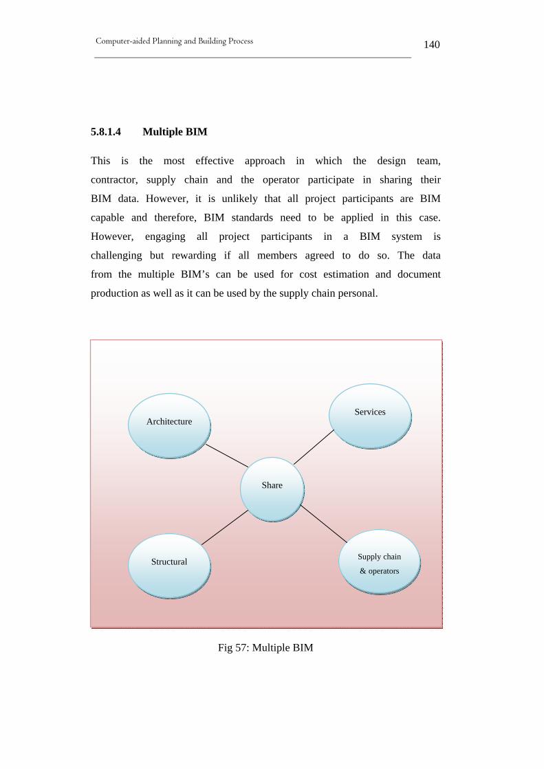
Computer-aided Planning and Building Process
140
5.8.1.4 Multiple BIM
This is the most effective approach in which the design team,
contractor, supply chain and the operator participate in sharing their
BIM data. However, it is unlikely that all project participants are BIM
capable and therefore, BIM standards need to be applied in this case.
However, engaging all project participants in a BIM system is
challenging but rewarding if all members agreed to do so. The data
from the multiple BIM’s can be used for cost estimation and document
production as well as it can be used by the supply chain personal.
Fig 57: Multiple BIM
Architecture
Structural
Share
Services
Supply chain
& operators

Computer-aided Planning and Building Process
141
5.8.2 Second category: BIM according to Tools
The second category promotes two BIM systems that evolved
according to techniques and CAD tools used to develop the systems.
The two systems are further explained as follows:
5.8.2.1 Object-Oriented CAD systems (OOCAD)
The OOCAD BIM compliant technology uses object-CAD software
that has been re-purposed for BIM such as Bentley Architectural,
Architectural Desktop, Allplan, etc. Initially, CAD system aimed to
automate the task of drafting mainly to replicate the traditional ways of
representing building information. Therefore, the focus of CAD
application was to represent 2D geometry via graphical elements, such
as lines, arcs, symbols, etc. In this case, walls, for example, were
represented as parallel lines and to establish some meaning behind
these graphical elements, the concept of layering was introduced to
group related elements together. For example, the lines that represent
walls are grouped on a given layer (wall layer). This techniques, allow
discrete 2D drawing files to be generated and plotted from CAD.
However, more complex information, such as the relationships
between elements could not be represented at this stage. In addition,
the emergence of 3D CAD also ignored this relationship and focused
almost entirely on creating geometry in support of visualization, and
more advance concentrated on creating realistic rendering and lighting
effects. Smilow [63] indicates that AutoCAD has greatly accelerated
drawing production process and significantly improved accuracy over
hand methods. However, these drawings are not “intelligent”
documents since no information is stored about the building systems or

Computer-aided Planning and Building Process
142
components. For example, a beam as produced by a 2D AutoCAD
document would be represented as a single line. Although the beam
size and related information could be shown as text adjacent to the
drawing lines, there are no information about the beam is known or
complied internally within the computer memory. On the other hand,
an intelligent document would also symbolize the beam as a single line
with size information adjacent to the drawing line. However, the
intelligent document stores the structural information associated with
that beam such as size, length, weight, and other relevant information
including all 3D properties.
Typically, Object-based data models define schemas that symbolize the
structure and organization of project data in the form of a class
hierarchy of objects. Utilizing of an object model offers consistence
project information, and served to integrate different project aspects
and facilitate sharing of data among project participants [46].
Recently, emerged OOCAD replaced the 2D symbols with building
elements which are capable of representing the behavior of common
building elements. Not only these building elements can be displayed
in multiple views but also having non-graphic attributes assigned to
them which add “intelligence” to these objects. This intelligence is
achieved by including parametric 3D geometry which means walls are
objects which can be stretched, joined, have height, be of a specific
cross-section type, and “own” associated properties, such as a fire
rating or insulation value. Also, windows and doors are represented as
objects and have relationship with the walls in which they are placed
and behaving accordingly. Indeed, realizing these relationships and
intelligent behaviors are just not possible in the previous CAD
paradigm [47].

Computer-aided Planning and Building Process
143
Howell and Batcheler [47] also believe that BIM is the latest
generation of OOCAD systems in which all building objects can be
included in one single project database that captures everything known
about the building. This makes BIM (in theory) the provider of a single
logical and consistent source for all information associated with the
building. Most importantly, OOCAD systems store some
(nongraphical) data about a building in a logical structure with the 3D
building graphics which assist users to produce information about
quantities and attributes, just as they extract 2D drawings from the 3D
graphics. Yet, object CAD systems remain anchored to graphics in
which additional tools and effort are required to keep the graphical and
nongraphical data in sync – to deliver the awaited benefits of BIM.
Some of these tools used to identity inconsistencies and errors in data
produced from object CAD models before the data is used for other
purposes such as Solibri Model Checker. However, the larger the
project, the greater the effort required to ensure co-ordinations and
avoid inconsistencies [48].
5.8.2.2 Parametric building modelers
Parametric BIM objects consist of geometric definitions and associated
data and rules in which geometry allows for no inconsistencies. This
means, if an object is shown as 3D, the shape cannot be represented
internally redundantly for example, as multiple 2D views. A plan and
elevation of the same object must always be consistent and the
dimensions are accurately guaranteed. Thus, parametric rules means
objects are automatically modify when inserted into a building model
or when changes are made to associated objects. Also, objects rules
will report any changes that violate object feasibility regarding size,
manufacturability, etc. However, the concept of parametric modeling
emerged as an extension of Constructive Solid Geometry (CSG) and

Computer-aided Planning and Building Process
144
Boundary Representations (B-rep) technologies based on university
research and intense industrial development especially by Parametric
Technologies Corporation® in the 1980’s. The fundamental idea
behind parametric building is that shape instances and other properties
can be defined and controlled according to a hierarchy of parameters at
the assembly and sub-assembly levels, as well as at an individual
object level. However, parametric design is not designing an instance
of a building such as a wall or door, rather it is defining a model family
or element class which is a set of relations and rules that control the
parameters by which elements instance can be generated. Typically, in
traditional 3D CAD every aspect on an element’s geometry must be
modified manually, whereas in a parametric modeler the shape and
assembly geometry are automatically adjusts to changes in context and
to high-level user controls [49]. In fact, a parametric object is a smart
object that can change its characteristics (size, materials, and graphic
look) but is consistently the same object. It enables designers to effect a
change of each parameter without affecting the others unless desired
[11].
In addition, parametric modeling engines use parameters (numbers or
characteristics) in order to determine the behavior of a graphical entity
and define the relationships between model components. For example,
“the diameter of a certain hole is 1 inch” or “the centre of this hole is
midway between these edges”. This indicates that the design criteria or
intent could be captured during the modeling process and allows easier
editing of the model and preserved the original design intent.
Moreover, parametric modeling allows for network of relationships
among and between all of the building elements and that illustrates its
strength. The ability to record, present, and manage relationships
between pieces of the building no matter where they occur in the
building thrive this technology. A parametric building modeler

Computer-aided Planning and Building Process
145
effectively manages the object data at the component level, but also
enables information about relationships between all of the components,
views, and annotations in the model. For example, a door to a stairwell
can be locked in a specific place to ensure certain clearance from the
riser; or a door can be locked at a specific distance from a wall to
ensure furniture clearance or pull-side clearance for accessibility. Also,
parametric modeling ensures that the entire model contains
information, not only the objects creating it. In other words, a
parametric building model combines a design model (geometry and
data) with a behavioral model (change management) in which the
entire building model and design documents are in an integrated
database, where everything is parametric and interconnected. Most
often parametric building modeling is compared to a spreadsheet where
a change made anywhere in a spreadsheet is updated everywhere
automatically. Indeed, no one is expected to have to manually update a
spreadsheet. The same is true for a parametric building modeler where
no one has to manually revise a schedule or design document produced
by a parametric building modeler [48]. The power of parametric
modeling is the ability to create relationships within objects and
between objects. For example, walls can be attached to roofs, so when
the roof is modified, all associated walls are automatically adapted to
the new roof shape [11]. However, the most commonly encountered
parametric building modelers BIM solutions are Autodesk Revit
platform for BIM and Bentley Generative components etc.
5.9 BIM issues and standardizations
The first issue arises when it comes to BIM implementation is
interoperability and compatibility among tools used to produces 3D
models for BIM systems. While the benefit of BIM and 3D modeling

Computer-aided Planning and Building Process
146
are well established and more firms are using BIM, each member of the
project’s team tends to have their own tool which cannot be integrated
with the others, resulting in duplication of information and poor
communication. Therefore, a common set of standards must be
established and implemented by all software vendors in the industry to
allow for better communications and to improve data exchange ability.
Additionally, the AEC industry requires an established standardized
process to successfully exchange and update model information.
A study executed by the National Institute of Standards and
Technology (NIST) of the U.S. Department of Commerce, found that
estimated $15.8 billion a year costs the capital facilities industry due to
interoperability problems in the industry [39]. However, some of the
most important standards that are being researched and developed
which aim to improve interoperability in the AEC industry are listed as
follows:
5.9.1 NBIMS (National Building Information Model Standard)
In December 2005 about 50 individuals, representing different industry
associations, developers and vendors, assembled under the National
Institute of Building Sciences (NIBMS) to find a way to overcome the
unacceptable losses due to inefficiency in the capital facilities industry.
Those people and organizations have been working solo for many
years to deal with various aspects of the problem and now they are
gathered together to discuss the possibilities and benefits to be
achieved by coordinating approaches to improve quality, reliability and
efficiency throughout the facility lifecycle. Following that meeting, the
formation and first products of the National Building Information
Modeling Standard Committee (NBIMS) have been achieved [50].
Computer-aided Planning and Building Process
147
In addition, since building information models are increasingly seen
throughout the public and private real estate and construction sectors as
a way to control costs and performance problems associated with
inaccurate and incomplete communications, the NBIMS Committee
objective is to facilitate life-cycle building process integration by
proving a common model that contains and describe the facility
information, common views of information and common standards for
sharing data between businesses and their data processing applications.
This common information model is expected to significantly reduce
costs, insurance liability, construction schedules, and operating
expense while improving performance and safety of facility. In this
manner the Facility Information Council (FIC) of the National Institute
of Building Sciences (NIBS) has formed a committee to structure a
National Building Information Model Standard (NBIMS). The mission
of the NBIMS committee is to improve the facilities over their full life-
cycle by promoting a common standard and integrated life-cycle
information model for the AEC industry and facilities managers
industry. This information model will enable free flow of graphic and
non-graphic information among project participants. The NBIMS
targets current and future BIM users in the field of Architecture,
engineering, construction, real estate, facility management and other
related fields. In fact, the new NBIMS committee counts for 26
organizations and businesses and over 80 individual working group
members. Now days, government agency and private organizations
demanding integrated service delivery approaches, use of ‘virtual
building models’ to reduce errors and omission, and the use and
delivery of digital datasets for facility operations, maintenance and
renewal to enhance emergency planning, management and response.
He anticipates using a common and open building information model
to facilitate these new demands and reduce delays, errors and liabilities

Computer-aided Planning and Building Process
148
associated with the construction process, while improving
performance, economy, safety and sustainability of facilities use [19].
5.9.2 IFC (Industry Foundation Classes)
The Industry Foundation Classes (IFC) data model is a neutral
and open specification that is not controlled by a singular or group
of vendors. It is an object oriented file format with a data model
developed by the International Alliance for Interoperability (IAI) to
facilitate interoperability in the building industry, and is a
commonly used format for Building Information modelling (BIM).
IFC allows information to be shared and maintained throughout a
construction project's life cycle: design, analysis, specification,
fabrication, construction, and occupancy [52].
Also identified by Brucker and others [21] as: IFCs are data
elements that represent the parts of buildings, or elements of the
process, and contain the relevant information about those parts.
IFCs are used by computer applications to assemble a computer-
readable model of the facility that contains all the information of
the parts and their relationships to be shared among project
participants. The project model constitutes an object-oriented
database of the information shared among project participants and
continues to grow as the project goes through design, construction,
and operation.
IFC is recognized largely by professionals as a data model developed
by the IAI (International Alliance for Interoperability) to simplify
interoperability in the building industry. In fact, major CAD vendors
were involved in the development of the IFC and its supporting tools,

Computer-aided Planning and Building Process
149
which was developed to handle 3D file data. However, it is a data
representation standard and file format used to define CAD graphic
data as 3D real-world objects which enable engineers and designers to
exchange data between CAD tools, cost estimation systems and other
construction-related applications. It also offers a set of definitions for
all object element types encountered in the building industry and a text-
based structure for storing those definitions in a data file. However, in
order to implement this IFC system, CAD vendors must create
programming within their own software structure. Thereby, “Save As
IFC” and “Read IFC” commands are provided, which map the IFC
object definitions into their CAD applications to represent these objects
[12].
Moreover, the IFC which was introduced at the 1995 AEC Systems
conference in Atlanta, as the “common language for interoperability in
the building industry” [15], is also acknowledged by Faulkner [12] as
an open international standard allowing AEC software vendors and
users to integrate and share data as well as combining all building
components into one BIM. However, BIM systems which are capable
of creating rich internal representations of building components
requiring IFC to add a common language to transfer that information
between multi BIM applications while preserving the meaning of
information being transferred. This adds more value to the model and
omits remodeling of the same building in each different application
[51]. In fact, the IFC has been available for several years and as of May
2003 it has been extended to include new functions for structural
engineers use. This is achieved in IFC 2x2 which incorporates
standards for communicating information related to both steel and
concrete structures [10].

Computer-aided Planning and Building Process
150
It is believed that IFC standard will impact the wide usefulness of BIM
by sharing these models across organizations, departments, IT systems
and databases without becoming dependent on other products or
vendors specific file formats. For example, the Danish government has
made the use of IFC format(s) compulsory for publicly aided building
projects, because of its aim to ease interoperability between software
platforms and enable architectural CAD users to transfer design data
between different software applications [53].
5.9.3 CIS/2 and IFC
The preceding section has briefly mentioned IFC 2x2 which
incorporates standards for communicating information related to both
steel and concrete structures. However, the IFC still lacks a
sufficiently complete representation of structural engineering to be
effectively used by structural engineers. Therefore, CIS/2 (CIMSteel
Integration Standard Version 2) has emerged as another open standard
that deals with one aspect of structural engineering which is steel
construction. By definition, CIS/2 is a digital standard for electronic
communication which originated from the Eureka CIMsteel (computer
Integrated Manufacturing for Constructional Steelwork) Project, a 10-
year $50 million research and development project in structural steel
that involved 70 organizations from nine European countries and
further developed by the American Institute of Steel Construction
(ASIC) to facilitate interoperability within the steel industry [79]. This
data exchange standard reduces the typical lead-time associated with
structural steel, thus allowing users to create a model in one program’s
native file format and transfer all the components and necessary
information to another program. In this case, and instead of starting
from scratch in an analysis package, users can simply import an

Computer-aided Planning and Building Process
151
existing model from different available design packages, ensuring time
saving and eliminating duplicated data. CIS/2 is also a translator
working as a bridge that allows software to communicate. For example,
it enables steel bidders to avoid recreating the building digital model by
using the model provided which shortens the biding process
significantly and ensures uniformity in the bids. It also eliminates the
confusion of bidders presenting different steel tonnages in which the
digital model clearly defines the piece count and tonnage of steel used.
They only variation in material quantities that can occur is the
allocation of steel connections which clearly identifies the tonnage
associated with connection material. Any change required for other bid
alternatives and updates are easily achieved via change to the digital
model [63].
However since the CIS/2 standard was developed for the steel industry,
inevitably though the questions come up: how does this standard fit
into industry and what place does CIS/2 have in the future of the
industry? The answer to that is BIM. There have been enormous
efforts to achieve harmonization between CIS/2 and IFCs which will
be an important component of BIM world. The aim is to have CIS/2 as
the repository for structural steel data while IFC standard will be the
repository for shared information in the BIM. Thereby, designers,
owners and decision-makers mostly concerned with clash detections,
avoidance and coordination issues will have access to high level,
shared data housed in the IFC standard whereas, steel detailing,
analysis, design and fabrication data will be housed in the CIS/2
model; allowing for a large amount of data, but only where needed
[12]. In fact, the IFC and CIS/2 share the same roots and they are both
closely related to STEP (STandard for the Exchange of Product model
data), which was initiated in 1984 by ISO (International Standards
Organization) to define standards for the representation and exchange

Computer-aided Planning and Building Process
152
of product information in general. Also, both use several resource
definitions (basic entity definitions such as geometry, cost, material
properties, loads, etc. that are used to define the properties of higher-
level entities) based on STEP and both applying the same STEP
modeling language (EXPRESS) for developing and defining the model.
Therefore, once BIM takes off and better interoperability is sought
between the AEC industry as a whole, the IFC and the CIS/2 need to
work closely together to improve the overall process of construction
[79]. Both organizations - the IAI (for IFC) and the AISC (for CIS/2)
have realized this and developed a translator to harmonize between the
two standards. The CIS/2-IFC translator is currently being developed
to handle three use cases:
1. IFC design to CIS/2 analysis.
2. IFC design to CIS/2 steel detailing applications.
3. CIS/2 to IFC for design coordination.
5.9.4 NSC (The United States National CAD Standard)
Reported by the buildingSmartalliance™ [89] and the National
Institute of Building Science [90], NSC simplifies the exchange of
design and construction data from project development throughout the
life of a facility. It coordinates the efforts of the entire industry by
classifying electronic building design data consistently allowing higher
degree of communication among owners and design and construction
project teams. The NCS primary aim is to reduce costs and produce
greater efficiency in the design and construction process.
NSC “Version 4.0” is intended for owners, architects, engineers,
contractors, facility managers, code officials, manufacturers, and
Computer-aided Planning and Building Process
153
suppliers which added the following improvements to older NSC
version 3.1:
• Expanded and reorganized CAD Layer Guidelines makes
locating layers name easier in addition to including new
telecommunications and electrical discipline layer names.
• Updated Uniform Drawing System includes new and revised symbols for geotech, security, masonry, plaster and updates and clarifies common drawing practices.
• Plotting rules are completely re-written which means line widths
are no longer needed to be mapped to color numbers as well as
new tables – gray scale, color, and line width tables.
• Additionally, the new version 4.0 includes documents in PDF,
Excel, and .dwg file formats, making it easier to search and
integrate the standard into CAD, BIM, costing, and other
software.
5.9.5 COBIE (Construction Operations Building Information
Exchange)
COBIE has been briefly mentioned as a tool used in the process of
construction documents handover. It is based on an open-source
platform (the IFCs) and designed to capture project information as it is
created, rather than rely on post-construction surveys or audits as is
current practice. Mainly to simplify the work required to capture and
record project handover data. This approach operates by entering the
data as it is created during design, construction, and commissioning as
illustrated by figure (58). Information entered into this approach are
provided by project’s team; thereby the space, system and equipment
layout are provided by the designer while product data such as make,

Computer-aided Planning and Building Process
154
model, and serial numbers of installed equipment are provided by the
contractor.
Fig 58: COBIE process overview Source: http://www.dtic.mil/cgi-bin/GetTRDoc?AD=ADA491932&Location=U2&doc=GetTRDoc.pdf
5.9.6 SDNF (Steel Detailing Neutral Format)
SDNF is used in steel detailing, and has become almost a standard for
data exchange between structural CAD systems. Unlike CIS/2 which
was developed as a comprehensive exchange mechanism for multiple
applications over the lifecycle of steel design, analysis, detailing,
fabrication and erection, SDNF supports the exchange of a steel
structure design between two applications. It is a standard format for
the exchange of steel structure elements (steel sections, plates etc.).

Computer-aided Planning and Building Process
155
5.10 Related Work (Real life situations and examples)
5.10.1 U.S. Army Corps of Engineers (USACE) is going BIM
The U.S Army Corps of Engineers (USACE) is implementing BIM
technology to its military and civil words processes. It has arranged for
the transformation process of Military Construction (MILCON) using
BIM as a new approach to its design process insuring that by the year
2008; BIM will be required for all military construction projects. They
believe that utilizing BIM technology will assist design and
construction activities to meet the critical deadlines of the MILCON
transformation process. However, the benefits of this new technology
are not limited to design and construction; but there is also the potential
that information contained in the BIM model could be used in the life
cycle of the building. In addition, data used during the design of the
BIM model can assist in the operating and maintaining the facility
surrounding the infrastructure.
However, when linked with systems that support life cycle
management, BIM allowed the USACE to better support its customers.
For instant, they used data from the BIM model to assist in installation
management and operations [32].

Computer-aided Planning and Building Process
156
Fig 59: Military Barracks BIM Model (USACE Honolulu District)
Source: https://cadbim.usace.army.mil/MyFiles/EdwardHuellBIM_FINAL.pdf
Fig 60: Fort Lewis Barracks, Seattle District
Source: http://www7.nationalacademies.org/ffc/mk_miles_usace.pdf

Computer-aided Planning and Building Process
157
Implementation issues encountered
Currently, the Centers of Standardization (COS) produces models with
information belonging to the rooms within a facility in order to
generate schedules for the construction drawings. On the other hand,
Administrators of Installation Management Systems (IMS) typically
field survey a building after construction to determine the layout of the
building and collect other vital information. However, this information
has already been collected by the COS during the development of the
model but lack of communication between participant lead to
redundancy in effort and therefore, wasting time and extra cost
encountered. Thus, information composed during the development of
the BIM model could used to support the IMS requirements.
Therefore, it is recommended that customers, owners and operators
should be involved in the BIM process to ensure collection of valuable
information to determine its impact on the BIM model. The interaction
of all entities early in the development stage, enable information to be
utilized in manners that are beneficial for the life cycle process.
5.10.2 New innovative office building in the heart of Vilnius, Lithuania
The SBA Group new innovative office building in the heart of Vilnius,
Lithuania is one of the major construction projects which utilize BIM
solution [54]. This project was scheduled for completion in the first
half of 2006 and is estimated to cost $20 million. Denmark-based PLH
arkitekter, which was chosen to produce the detailed design, has
decided to design the new office building using Bentley’s information
modeling (BIM) including Architecture. One reason for PLH’s
selection of BIM solution was the flexibility that offered to the
designers and the architects to sketch the unique forms envisioned for

Computer-aided Planning and Building Process
158
this building. Especially, helping architects in designing the main
bearing structure, which consists of eight intertwined steel helixes that
stand together as a unified tower around a central atrium. Using BIM
solutions proved to be a flexible and quick approach for sketching this
structure allowing for producing a series of models for evaluation in
very short time frame.
Fig 61: SBA Group new innovative office building (Vilnius, Lithuania) Source:
www.bentley.com/itIT/Products/Bentley+Architecture/Project+Gallery/Image+gallery+PLH+SBA1.htm

Computer-aided Planning and Building Process
159
What is more, PLH won the designing competition amongst Europe’s
top architectural firms by producing a number of different concepts
from many different views for evaluations and the best concept was
selected to be their entry in the office building competition. The 3D
model was designed so that several architects could work on it at the
same time by dividing this model files into building parts and all
individual models were referenced into the main model to the entire
building.
In addition, PLH agreed to use DWG as the data exchange format since
they use Bentley’s BIM solutions to generate production drawings and
the building engineer (Ramboll building and construction) uses DWG-
based software. This eliminates the need for PLH to double -produce
the steel portion of the model by referencing the Ramboll’s DWG-
based steel model directly into the PLH BIM main model. However,
due to the limitation of DWG-based systems, only the geometry of the
model and not the inherent intelligence behind the objects could be
exchange.
Overall, the major benefits of using BIM solution were the constant
geometry check of the model parts and their relationship. It was
possible at any time during the process to inspect design solutions and
evaluate these solutions for aesthetic and functional value. Also,
visualization in the form of still images and animations could be
produced on day-to-day bases. PLH acknowledge the benefit of using
BIM solution without a doubt. In fact, the production drawing started
early in January of 2004 and was completed by April 1, 2004. It was
clear after only a few weeks’ work that the designing process went far
beyond what could be accomplished by traditional 2D methods. While
this project could have been drawn in 2D, these factors must be taking
into consideration if the project had been drawn in 2D:

Computer-aided Planning and Building Process
160
1) the man-hours would have been at least doubled,
2) the time required would have been extremely high,
3) errors because it would have been so difficult to maintain
consistency between the different views.
4) the same level of detail could not have achieved using 2D
method.
5) the series of constant geometric control checks that come
inherently from the 3D model would have been impossible to
achieve by 2D techniques.
6) the drawings generated from the 3D model presented a high
level of sophistication, detail, and accuracy that is seldom seen
in traditional 2D drawings.
Additionally, PLH realized that using BIM solution as the basis for the
entire design process saved them time and improved accuracy. They
have completed this project in about half the time that would have been
required using conventional 2D methods, because they were able to
detect errors early and use the model to automatically generate
drawings and sections. Detecting errors early in the design stage made
the drawing package more accurate, which will save money as the
building is constructed.
5.10.3 Denver Art Museum Expansion
This project is an addition to the existing “Denver Art Museum” which
is more than doubles the existing building. The steel skeleton structure
covers 230,000 square feet of titanium shingles, and form a work of art
in its own way. In addition, the 2,740-ton steel superstructure is an
interwoven cluster of leaning braced frames and trusses. Thus, more

Computer-aided Planning and Building Process
161
than 3,100 pieces of steel are included by 20 sloping planes that from
the structure. The structure extends out 194-foot, 167 feet over and 100
feet above the avenue below. It is a true test to the power of BIM and
integrated teamwork in which the design and construction of the
building was made practical.
Using BIM techniques throughout this project allow for understanding
the spatial relationships and detect conflicts ahead of actual
construction. This approach enables “virtual construction” prior to the
first workers arriving to the site and before fabricating the complex
components of the structure. Moreover, during the design process, the
architects created a coordination model that allowed 3D coordination
of all participants. After defining the planes of each wall, a 3D
wireframe model was developed and exported to structural analysis
packages.
Fig 62: Computer generated image showing the steel frame (red)
Source: http://www.designbuild-network.com/projects/dam/dam3.html

Computer-aided Planning and Building Process
162
Fig 63: Addition to the existing Denver Art Museum
5.10.4 Park Hospital in Novi, Michigan
This project is a 500-square-foot, six story hospital that visibly
established a relationship between the pastoral site, the scientific
precision of modern medicine, and the human element of care giving.
The size and complexity of the building shape, the integration of the
new building with and existing building and the requirement of the
location formed a great technical challenges for the design team. These
challenges and obstacles were minimized using BIM techniques which
yield many benefits during the design phase of the hospital. For
example, adjustments and changes dealt with as the project progressed
without impact on the designated schedule.

Computer-aided Planning and Building Process
163
Fig 64: Park Hospital in Novi, Michigan Source: http:// www.nxtbook.com/nxtbooks/bemagazine/vol3issue4/
Additionally, the implementing of BIM throughout this project, the
NBBJ (architecture and design firm) was able to use a single, common
model that help the design team to clarify and understand relationship
between all the building components and how they would interact with
one another, as well as building interacting with the surrounding site.
BIM proves a valuable tool in which 10% of total cost and three
months time were saved during the design phase of this project.
Jonathan Wilch, principal at NBBJ [61], added that using BIM solution
in this project has significantly reduced the hours spent on design,
while improving the quality and the representations of the project. In
addition, the design team were able to better understand the complexity
of the design, and to broaden their work group to include engineers and
outside consultants to resolve issues and produce an integrated and
coordinated set of documents. Yet, this approach allows the design
team to use cell component modelling which increases the efficiency
when updating the design, especially for repetitive components.
Moreover, the design team were able to analyze different value-
engineering alternative to determine their impact on the project cost

Computer-aided Planning and Building Process
164
and schedule. They were also able to carry out significant analysis of
exterior material allocation, allowing for effective design decisions
regarding material quantities and use of sustainable material. The
model was also used to determine solar loads, allowing cooperative
work with engineers to locate the building to better respond to the
position of the sun for lighting. In fact, using BIM technique allows
the design team of a large project to tackle the project in a more
efficient way. The team members who each assigned to a particular
task or element were working together on the same design, producing
date directly from the digital model and output to a laser-cutting device
and 3D printers. Throughout this project, designers were able to
quickly produce updated, hard-copy documents as needed from the
digital model. They were also able to exchange 3D models with their
engineering consultants and construction partners more often and
earlier in the process, which improve integration of the architectural
and engineering information to avoid interferences and enable the
constructors to visualize the project prior to construction.
5.11 Case Studies
Two case studies are provided by Azhar among others [66] to illustrate
various tangible and intangible benefits yield using BIM for actual
projects which are obtained from the Holder Construction Company,
Atlanta, Georgia.

Computer-aided Planning and Building Process
165
5.11.1 Hilton Aquarium, Atlanta, Georgia:
A hotel and parking structure project that scope is about $46M
in which BIM is employed to coordinate the design, detect
clashes and arrange the work sequences. The BIM used in this
project consist of the architectural, structural and MEP system as
shown in figure (65). The BIM was developed during the design
development phase using detail level information provided by
subcontractor based on drawings from the designers.
Fig 65: BIM consists of architectural, structural and MEP system
Source: http://www.neduet.edu .pk/ICCIDC-I/Conference%20Proceedings/Papers/045.pdf
The following benefits are achieved from this approach:-
• About 590 conflicts between structural and MEP components
were identified and resolved prior to field installations. A saving
of about $200,000 in extras and avoiding months of delays were
achieved.
• Improve design coordination.
• Eliminate of additional costs.
• Allow owner scope revisions without issuing change orders.
• Design changes were accommodated.

Computer-aided Planning and Building Process
166
5.11.2 One Island East Project, Hong Kong:
This case study is to document the implementation of BIM to manage
the functional and financial relationships between design, construction
and facility management on a large, complex project by an owner-
developer. The goal was to manage information more efficiently and
save time and cost over the project life cycle. The seventy floors
reinforced concrete and aluminum curtain wall skyscraper scope is
about $300M and completed in May 2008.
Fig 66: BIM of One Island East (OIE) Project Source: http://www.neduet.edu .pk/ICCIDC-I/Conference%20Proceedings/Papers/045.pdf
However, using BIM throughout this project allow for managing all
project coordination issues. In fact, over 2000 clashes and errors were
identified prior to biding and construction, which yield cost savings
that would not be realized using a traditional 2D process.
Computer-aided Planning and Building Process
167
5.12 Conclusion
This chapter has thoroughly explored Building Information Model
(BIM) as a newly emerged technology which is being used by some the
AEC industry in many projects. However, although many great
potentials and benefits could be realized by BIM, the question is how
and at what cost? In addition, there are several issues and obstacles
that need to be addressed and tackled in order to ease and smooth the
transactions from ordinary deliverable construction documents designs
to a common BIM model. However, some of the major issues which
obstruct BIM adaptations and endorsement industry wide are discussed
as follows:
5.12.1 Who Owens BIM?
The shift from the historical deliverable construction documents to a
BIM model has fuelled awareness in the design community over “who
owns the final BIM?” If architects are not involved in the whole
construction process, they fear their vision for a project can be
compromised. Overall, there is a fear among designers and architects to
be left behind in the BIM movement. Although generally aware of the
BIM development, designers and architects are not actively driving the
BIM movement [36]. According to Yoders [27], Scott Mackenzie said:
architects are concerned if general contractors own the BIM, they will
be left out. They fear that contractors will be selling the model to the
client and just using architects as consultants merely to do the design
task. In addition, designers fear about the potential misuse and theft of
their digital intellectual property.
Yet, the issue of BIM ownership becomes even more complex when
the final model is a collection of data from many models in which
Computer-aided Planning and Building Process
168
many parties have contributed to it. Consequently, as the use of BIM
grow more and more, certain standards will have to evolve to who is
responsible for what and to what extent. An effort in this direction is
lead by the National Institute of Building Sciences (NIBS) which is
currently involve in developing standards to who is responsible for
inputting what information into a model[70].
5.12.2 Work in a Multidisciplinary Coordination
All participant of a construction project should be taught
multidisciplinary coordination of the project along with BIM software
training, rather than simply teaching them how to design a 3-D
environment. However, transition to BIM should be driven by
architects, engineers, and other design professionals who would be
working on a common model as a team [27]. In fact, this common
model can be accessed for coordination or electronically interchange
by all participants in CAD environment. Off course, because not all
participants within a project have been educated in the same way, it is
inevitable that will be conflicts between them. Therefore, teaching
multidisciplinary coordination along with BIM to project’s team is
necessary to achieve collaborative process and joint decision-making.
5.12.3 Legal and Liabilities Issues
Although BIM primary aim is to allow for collaborative framework for
design and construction, this new method of designing and
constructing buildings is challenging the existing legal system and
insurance structure that protects project participants. This is in fact
blurring the line of responsibility among participants as integrated

Computer-aided Planning and Building Process
169
practice continues to develop. This also raises the question concerning
protecting each participant involve in the building process, as well as
the intellectual property and confidentiality of information related [59].
AGC [70] argues that the existing legal environment is not able to cope
with all risk management implications associated with the emergence
of BIM as a tool that has dramatically changed design and construction
process. The question is “what are the liabilities associated with
participating and collaborating in the model? Although these issues are
acknowledged, resolving them remains an open question. In fact, some
fears that concern over liability, risk allocation, shifting and sharing
associated with BIM may discourage many from experimenting with it.
Additionally, it has been reported at Applied Software’s Executive
Roundtable on “Confronting the Challenges and Opportunities in
Integrated Practice, collaborative Design and BIM”, that BIM is
changing the standard method of design/bid/build process to a “shared
project model”. Tony Smith, senior partner for Construction &
Infrastructure Projects at Kilpatrick Stockton, LLP indicates that BIM
is recognized as a new project delivery method and not an influence on
traditional construction approaches, and among comes new risks, new
rewards and new relationships. He also argues that seeking to fit this
new BIM concept within the existing legal structure is similar to the
old saying about trying to fit a square peg into a round hole. Legal
experts agree that in order to reach BIM maximum goals and to support
collaboration between parties while providing legal protection, industry
standard contracts, insurance policies and surety bonds must be change
to suite this new technology. Last year, two new standards form
documents to facilitate the transmittance of digital data have been
published by the American Institute of Architects (AIA) to allow for
transmitting data in a digital working environment and maintaining
control over its future use. The digital Data Licensing Agreement

Computer-aided Planning and Building Process
170
(C106™-2007) and the Digital Data Protocol Exhibit (E201™-2007) to
allow for sharing digital data between project participants in
accordance with agreed-upon protocols form transmission, format, and
use of the data [60]. The new AIA standards could smooth the
transition to collaborative between parties by laying out conditions for
digital data exchange among project participants; include all members
from the owner to the mechanical subcontractor [59].
Indeed, while BIM offers improvement in the construction quality and
efficiency, current business and contract models hamper the adoption
of such collaborative teamwork. Experts believe business models and
contract relationships must be rewritten to reward “best of” project
decision-making and to distribute responsibility among all parties
equitably, while providing adequate protection for the intellectual
property and confidential information embedded in a BIM. Also,
Richard Burroughs, president of Applied Software [59] add, BIM offer
a better, more efficient and cheaper method to design and construct
buildings but careful consideration must be given to the legal issues for
it to extend beyond the early adopter phase into widespread us.
In addition, missing of legal and insurance protection to support a
collaborative project delivery framework was reported by Hartmann
and Fischer [36] in the “2007 AISC-ACCL eConstruction Roundtable
Event Report” which hinder the vertical integration between
participants involved in a construction project. Also reported is the lack
of understanding of new technology by lawyers who blame the court
decision to be focusing on the warranty of the rights of the individual
stakeholders of a project and not focusing on a collaborative
assessment. Indeed, lawyers need to keep up with current technological
developments to understand the legal requirements of a BIM
framework. In fact, insurers and lawyers are struggling with the new
form of collaborative project delivery introduced by BIM technology;

Computer-aided Planning and Building Process
171
they admitted to be behind the industry movement and need to keep up
and clearly announced the need for help of other AEC participants to
catch up. In addition, insurers are still hesitating to change their
policies until better understanding and clear vision of the consequences
of BIM implementation on AEC projects is achieved. Thus, they must
be provided with case studies and other historical data for a b better
legal and financial understanding. Generally, the industry seems to be
moving towards BIM without well defined legal or insurance policies
at hand. However, firms who decided to wait until then might be left
behind the fast technological developments.
Certainly, BIM and other similar technologies will eventually change
the way project teams are typically interacting and so will the
contractual language that defines them. However, this issue of
uncertainties that associated with BIM should not hamper the
embracing of this technology. With time, the typical tri-party approach
to design and construction will be replaced by “Integrated Practice”
and collaboration [70].
Moreover, Faulkner [12] concluded that digital does not always mean
computable. For instance, a financial data can be created using word
processors which include columns and rows of the numeric data.
However, most of the numeric calculation and modifications must be
done manually although the data is digital. On the other hand, the same
financial data can be created in a spreadsheet version that contains
numerical values, relationships and sophisticated calculations abilities
although it looks identical to the word processor version. The data
created in the spreadsheet is computable whereas the word processor
representation is not, even though both look identical and digital. This
is the case in the building industry for the most parts, which has
adopted the word processor approach to documenting building designs
for the past 20 years. Ordinary CAD tools are used widely to create

Computer-aided Planning and Building Process
172
electronic drawings of buildings and this applies also to some 3D
models which are little more than 3D drawings. Although the output of
these systems are similar to the output of a BIM solution (just like the
resemblances in our previous example between the financial data table
in the word processor and the spreadsheet) it is not computable
information.
However, the use of a single ‘total’ BIM on large projects, including all
architectural, structural and services object information is still not
available and may never be totally possible, due to the mass of
information and subsequent data compression that will be required
[81]. Currently most of these thoughts and wishes are exist only on
paper. Through AEC professionals, participates and findings in
literatures, many BIM systems that are achieved in the industry
includes only two or three models, generally architecture and structural
models and in some cases the MEP model. This is reflected in the
coming chapter which aims to propose a BIM system to generate
building abstractions such as plans, sections, elevation, details, and
schedules.

Computer-aided Planning and Building Process
173
6 A proposed BIM System
Considering Iran is one of the most earthquake endangered places in
the world. Just, the Bam earthquake in 2003 destroyed the city in
matters of minutes and killed more than 30,000 people [62]. This raises
the necessity to construct earthquake resistance building to minimized
damages and save lives. Therefore, a modern office building project is
being design at the Berlin University of Technology (TUB) which aims
to enhance earthquake resistance and energy consumption with respect
to the climatic comfort of Iran. This is due to an early mentioned
agreement between The Building and Housing Research Centre
(BHRC) in Iran and TUB to enlarge and broaden their cooperation and
establish collaboration on further academic and research related
development activities.
Furthermore, the preceding chapter has discussed BIM technology in
details including its uses and implementation within the AEC industry
covering most common aspects and related issues. However, this
chapter will present a practical example of a proposed BIM system
using available data through the previously mentioned agreement. The
system is to benefit from the availability of designing information of a
proposed office building in Iran (2D plans) to propose a BIM system to
generate building abstractions such as plans, sections, elevation,
details, and schedules. Mainly, this chapter will use the available 2D
plans to design 3D models of the office building to be used in
developing the proposed BIM system. The final results and findings
will be discussed throughout this chapter in more details.

Computer-aided Planning and Building Process
174
6.1 System Architecture
Typically any BIM system (at least within the building industry)
consists of several models (inputs) produced by different specialized
individuals with different levels of details and different software tools
[2]. Several 3D models could be included within a BIM system
however; the followings are examples of the most commonly produced
models as BIM system’s inputs:
• Architectural Model (walls, floors, roof, circulation, special
objects, etc.).
• Structural model (structural systems).
• MEP models (mechanical, electrical, plumbing).
• FP model (fire protection).
• Specialty models (equipment, finishes, temporary construction
such as: scaffolding, form work, trenching, etc.).
• Site model (context-land, buildings, landscape, etc.).
• HVAC model (heating, ventilating, and air conditioning).
These models are possible components of the system input where as
the output of the system will include extracted drawings, three-
dimensional virtual models of buildings, evacuation plans, schedules,
budget estimates, fabrication drawings, etc.
However, while BIM systems could include anything related to the
building industry including facility life cycle and energy issues, this
proposed BIM system consists of two 3D models of the architectural

Computer-aided Planning and Building Process
175
and structural systems of the proposed office building (see system
component section). Thus, these models were created during the
design development phase using details obtained from the designers,
utilizing Bentley’s MicroStation software. Two segments of Bentley’s
MicroStation software (architectural and structural) are used to create
the proposed system components. The first is used to produce the
architectural model which consists of all 3D elements associated with it
such as walls, floors, roofs, doors and windows, furniture, etc.
However, the structural model is produced using Bentley’s structural
software which includes all structural elements and membranes. This is
also going to affect the way data and reports are extracted and
produced from the proposed system. This is mean, all architectural
related data, drawings and quantity repots will be produced using
MicroStation Architecture software; whereas fabrication, workshop
drawings and steel lists and specifications are achieved using
MicroStation Structural software. As a direct result, two separate
databases for each application are produced along the way for each
building system. Bentley’s architecture database included all
information need to produce drawings, sections, and bill of quantities
for architectural model elements; and Bentley’s structural database
held data regarding steel membrane that form the building frame
(columns, girders, bracing, etc.). This means, in order to get the right
information and produce accurate media, the BIM model must be
opened in the specific application. For example, to extract a shop
drawing from the system, MicroStation Structural is utilized to open
the 3D model using the associated database to perform the task.
Moreover, the functionality and usability of the proposed system will
be the focus and discussion of this chapter. The discussion will explore
the system in more details including: system components (system
architecture), data extraction, as well as categorizing results of the
Computer-aided Planning and Building Process
176
system by disciplines. In addition, findings and final results of the
system will be explored and elaborated on as well as categorizing the
end results according to types and disciplines will be illustrated.
6.2 System components
6.2.1 System Input
Two 3D models of the proposed office building are produced as inputs
to form the proposed BIM system as follow:
6.2.1.1 Structural model
The structural model (Fig. 67) is created using Bentley’s MicroStation
TriForma Structural which contains all structural elements and
members used in the building (footings, columns, girders, etc.) and will
be used to produce information regarding structural detailing and
documents. Thereby, it will be used to produce a variety of different
types of structural construction drawings such as foundation plans,
framing plans and detail drawings (elevation, sections, and details and
many others).

Computer-aided Planning and Building Process
177
Fig 67: 3D structural model
6.2.1.2 Architectural model
The architectural model (Fig. 68) which is being used in forming the
BIM system is created using Bentley’s MicroStation TriForma
Architecture solution. It includes all architectural elements forming the
office building such as walls, frames, glass, floor, concrete, etc. This
model will be used to produce any information related to architectural
as needed. This includes drawings, schedules, and report extraction that
occurs throughout the life cycle of the facility, and beyond.

Computer-aided Planning and Building Process
178
Fig 68: 3D architectural model
6.2.2 System Output
Once the two 3D models are combined to form the BIM system,
different outputs (i.e. views and documents) are expected to be
extracted from the system as illustrated by the proposed BIM System
Chart in figure (69) which are:
6.2.2.1 Visualization
Different tools and means will be used to extract visualization data
from the proposed BIM system such as rendered views, 3D
visualization, animation, simulations and videos. This could be
achieved using different tools such as on computer screens
visualization, Google Earth tools or by Inserting the models into a
“*.pdf” file which are explained in more details in the following
sections.
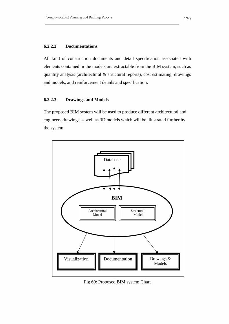
Computer-aided Planning and Building Process
179
6.2.2.2 Documentations
All kind of construction documents and detail specification associated with
elements contained in the models are extractable from the BIM system, such as
quantity analysis (architectural & structural reports), cost estimating, drawings
and models, and reinforcement details and specification.
6.2.2.3 Drawings and Models
The proposed BIM system will be used to produce different architectural and
engineers drawings as well as 3D models which will be illustrated further by
the system.
Fig 69: Proposed BIM system Chart
BIM
Visualization Documentation Drawings & Models
Database
Structural Model
Architectural Model
Computer-aided Planning and Building Process
180
6.2.3 The proposed BIM System in Action
Once the office building design data is digitally captured in the 3D
models and system is developed, several tools and methods are
conducted to present the data as coordinated documents which will be
shared across disciplines and serve as a centralized design management
tool. However, extracting and producing views and documents from
the proposed system are further illustrated as follows:
6.2.3.1 Extracting visualization from the BIM
Visualization has been an effective way to communicate between
project participants in the building industry and has proven beyond
doubt to be a vital aspect of 3D modeling if it’s not the core aspect. It
empowers designers and decision-makers to view their design and help
them understand how the proposed building will function before actual
construction started. This also allows detection of interferences and
hindrance early in the design process and therefore, costly changes
during construction are avoided. However, Kymmell [2] claimed that
incorrect visualization of the project information is the largest problem
when it comes to planning and construction. He argued, in order to
correctly present the building project, it must be fully visualized,
understood and communicated to avoid arising problems during
construction.
Therefore, visualization evolved as essentially 3D tool to assist
designers and decision-makers to better understand and study the
facility in a real-like environment, saving time and avoiding
inconsistency. Now a day’s the industry is dominated by VR
technology in which realistic photo-realism are generated and not only
a still view.

Computer-aided Planning and Building Process
181
However, the proposed BIM system is utilized to produce views,
rendered pictures, documents and videos of the office building using
chosen methods and tools as follows:
1.1. On Screen Visualization.
2.1. Google Earth Environment.
3.1. Inserting 3D model into a “*.pdf” file
6.2.3.1.1 On-Screen Visualization
Producing rendered views and photos of the office building is achieved
using Bentley’s MicroStation architectural program. The proposed
BIM system produces some photorealistic images and rendering of
office building including adding desired textures and materials to
improve visualization and provide earlier 3D visualization of the
building, as shown in figure (70).

Computer-aided Planning and Building Process
182

Computer-aided Planning and Building Process
183
Fig 70: A sample of rendered photos produced by the BIM system
In addition, this system allows for walkthrough techniques allowing
audience to view the project in a real-life like situation. This is
achieved in Bentley’s MicroStation Architectural, by specifying a
defined path around the model whereby a fixed camera takes a series of
shots automatically along this path and saves them as *.jpg files. These
files (pictures) can be then loaded to MicroStation video maker to
create a video to be viewed in MicroStation or can be saved in different
format. For the purpose of this research, two types of visualization
videos are produced, one illustrates the building as a wiremesh as
shown in figure (71) and the second shows the building in ray trace
rendered mode (figure 72). The program allow for the created videos to
be saved in different format, however the produced videos are saved as
Windows AVI (*.avi) files.
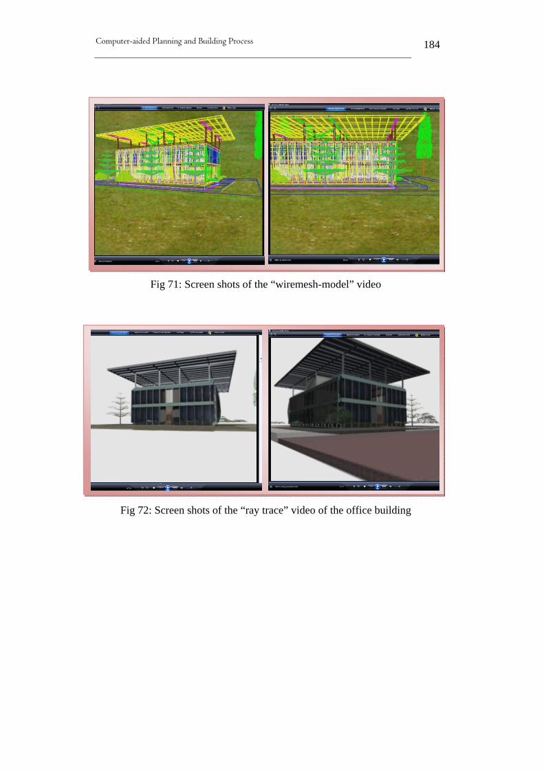
Computer-aided Planning and Building Process
184
Fig 71: Screen shots of the “wiremesh-model” video
Fig 72: Screen shots of the “ray trace” video of the office building

Computer-aided Planning and Building Process
185
6.2.3.1.2 Google Earth Tools
The second tool used to visualize the office building is Google Earth
which was recently linked to MicroStation. Since the linking between
MicroStation and Google earth, a new Google Earth setting tool was
introduced by MicroStation to allow for exporting models to Google
Earth environment. As mentioned earlier, the exported model will have
all associated data exported with it, so it can be modified and viewed
just as in its original program. However, Google Earth has been already
used earlier in chapter 4 as a visualization tool for the VRCE.
Additionally, the office building model has been also used there as an
example of a detailed 3D model viewed by Google Earth. The process
of exporting the model to Google earth and the results are further
explained next.
6.2.3.1.2.1 Visualizing the BIM in Google Earth Environment
The process of exporting MicroStation’s models to Google Earth (as
illustrated in the help document of the program) typically includes:
1. In Google Earth, creating a placemark at the required location
and save it as a “kml” file.
2. In the model, defining a monument point that matches the
location of that placemark.
3. In the design model, exporting the model to a Google Earth
“kml” or “kmz” file using the Google Earth setting tool “Export
Google Earth (KML)”.
Another alternative to exporting 3D models to Google Earth is to firstly
export the model to COLLAborative Design Activity “Collada (.dae)”
file and then add this model to a specific location in Google Earth.

Computer-aided Planning and Building Process
186
However, unlike exporting the model directly from MicroStation,
adding the model to Google Earth as a “Collada” file will not include
any layers or saved views and only navigation is allowed in this case.
In addition, models exported or added to Google Earth can only be
rendered as smooth no more.
However, the following (figure 73) are some captured views of the
office building model which was exported by the proposed system to
Google Earth environment. While, there are considerable benefits
viewing the model inside the Google Earth environment, there are also
some drawbacks associated with this tool which are discussed earlier in
chapter 4. However in general, the system allow for navigating the
model as in its original program in addition to zooming in and out as
required. It was also possible to switch layers of specific elements to
revel other hiding elements. So, one could explore the model with most
visualization options enabled within the rich texture of Google Earth
Environment.
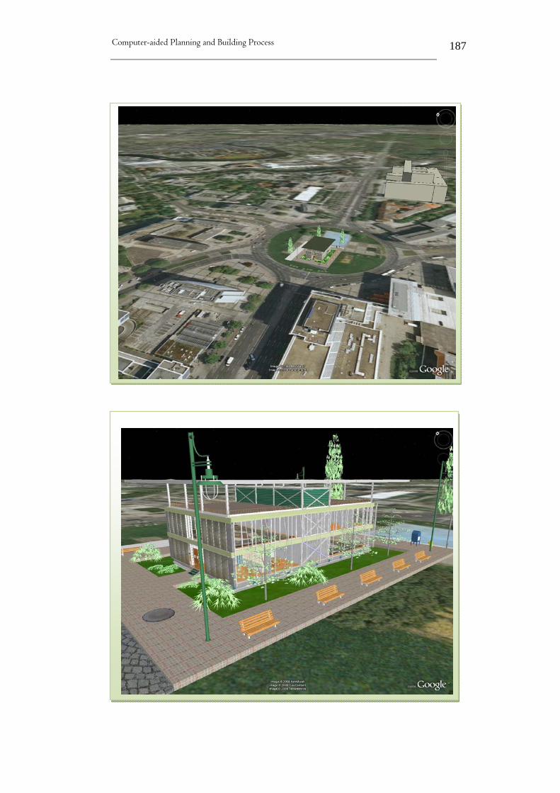
Computer-aided Planning and Building Process
187

Computer-aided Planning and Building Process
188

Computer-aided Planning and Building Process
189
Fig 73: Views of the office model in Google Earth environment
Computer-aided Planning and Building Process
190
6.2.3.1.3 3D Model in PDF Files (PDF Images)
Thirdly, Adobe® Reader® is counted for the third tools used as
visualizing method of the BIM model. Starting from Adobe® Reader®
7.0 and higher supports the insertion of 3D content within PDF
documents is allowed. This new technology enables publishing of 3D
visualization, designs, models and data, utilizing the free Adobe® PDF
Reader.
However, to embed 3D content within PDF documents, MicroStation
Uses “Universal 3D” (U3D) format which was introduced by the 3D
Industry Forum (http://www.3dif.org) as means for transferring three-
dimensional data from CAD systems to mainstream applications, to
export geometry directly to U3D or to seamlessly create PDF
documents with embedded U3D objects. Bentley was one of the few
companies that supported U3D and therefore, all Bentley applications
can automatically be converted into PDF files [56].
This enable CAD users to create PDF documents of their design
including 3D content that contain any visualization data and settings
that exist within the design file, such as lights, materials, texture map,
and animation or flythrough in addition to saved views [57].
However, in MicroStation, the procedure of creating PDF documents
with 3D content is similar to printing a standard 2D document. When
printing, the user enables the Plot to 3D settings in the print dialog box
and chooses “Bentley driver”.

Computer-aided Planning and Building Process
191
6.2.3.1.3.1 Inserting BIM into a PDF document
The BIM model will be exported as a PDF file including all
visualization data that associated with it. Once opened in Adobe®
Reader®, the user can navigate and interact with the BIM similar to
original program. For example, all levels, references, animation, and
saved views are conveyed with the model and they will react in the
same way as in original program. This enable users to switch desire
levels or lights on or off and select the preferred saved view as
required. They can also, rotate, zoom, select and explore to reveal
hidden information, all in the context of a PDF file. In addition,
Adobe® Reader’s users can add their own views to the model and
saved them as they like. This technique makes practical distributing
and interactive of 3D models to everyone with the free Adobe® Reader
possible which take up less space on computer’s hard drive.
However, the proposed BIM system has inserted the office building
model into a “pdf” which acted similarly to its original program
including saved animation. It was possible to switch layers and lights
on or off, rotate and zoom around the model and explore information
just as a CAD program in addition to the saved animation which
functioned automatically within Adobe®. Some screen shots of the
inserted model are provided by figure (74).

Computer-aided Planning and Building Process
192
Fig 74: The BIM is inserted in Acrobat as “pdf” file
6.2.3.1.3.2 Advantages and disadvantages of 3D plot in PDF
Adobe PDF animations is the ideal format for sharing walkthroughs
and flyovers, making proposals for review, or exchanging and
communicating construction sequencing [58]. The ability to export the
complete 3D model as a PDF file has many advantages, such as:-
1. Adobe® Reader® is free and easy to use.
2. Convey complex 3D designs to all project participants or clients
no matter what tools they use.
3. Export photorealistic renderings or shaded 3D models directly
from MicroStation.

Computer-aided Planning and Building Process
193
4. Visualization data and setting such as lights, materials, texture
map, and animation are carried on to the PDF file.
5. Saved views, references and levels are also included within the
PDF file and function similar to original software.
6. Some MicroStation users realized benefits of 3D PDF in the
following:-
• Using 3D PDF to demonstrate design intent in their proposals.
• Communicate project progress in their newsletters using 3D in PDF.
• Using 3D in PDF to visualize multiple stages in the construction process.
• Including 3D in PDF as an effective teaching aid in their training manuals.
However as in the case of many techniques and tools, inserting 3D
models into Adobe® Reader® to visualize BIM has some draw backs
such as:-
1. Plotting a 3D model in PDF with animation required a great deal
of computer memory otherwise; this could be a time consuming
process.
2. Only activated levels in the original model at the time of plotting
will be conveyed with the model.
3. Visualization is limited to the outside of the model (flythrough),
whereas in other techniques such as Google Earth one can go
deep inside the model and perform a walkthrough.
4. Adobe® Reader® PDF animations do not offer any rich
geographic imagery or surrounding that imitates reality like in
Google Earth.

Computer-aided Planning and Building Process
194
6.2.3.2 Extracting Documents from the BIM
BIM provides the greatest opportunity for improvement in construction
documents since CAD. It automates material take-off to aid design
verification and material procurement [30]. It is also considered as the
building industry’s application of product information modeling
concept, where the product is a building. However, its Implementations
used to be very “geometry centric”, but now a day’s BIM is expanded
to include properties for use in analysis applications like energy use
simulation, quantity take-off, cost estimating, construction planning
and many types of engineering analysis [15].
In addition, digital models enable designer to examine different
scenarios and answer ‘what if questions’; for example, what if we
replace the tiles with wood? Or what happens to the cost if we
increased the height of the ceiling? Nowadays, designers are
answering these questions in a matter of minutes or hours where it used
to take days and weeks to answer them. Although, three-dimensional
computer generated models have been used since the 1970’s and
designers have long used 3D representation as part of their analysis and
communication processes, in most conventional software systems,
these 3D models are created and maintained separately from 2D
representation and thus requiring manual coordination between the 3D
representation and the 2D contract documents or construction
drawings. In this case, it is the designer’s responsibility to make sure
that changes are incorporated to maintain consistency. However in
digital models, the 2D and 3D representation come from the same
source (database), so consistency is ensured. Digital models also
simplify the generation of 2D reports by slicing the model; designers
can easily generate floor plans, sections, elevations etc. Effectively,
these intelligent models may be assembled by the design team object
Computer-aided Planning and Building Process
195
by object, system by system, in a digital environment. This will not
only offer designers 3D visualization at any time during the design
process, but also enable them to extract, almost instantly, much richer
information and documentation than they could get from 2D drawings.
Additionally, integrated digital models give designers instant access to
relatively complex design information such as area calculations which
is a task performed several times during the course of sorting out a
building program. Subsequently, a digital model should allow the
design team to derive and update area calculation results effortlessly
whenever the design changed or modified. Likewise, cost information
should be quickly generated by attaching to any object the cost unit.
This can count or measure the objects and insert them in a schedule,
providing quick access to cost information whenever a change is made
[28].
However, the proposed BIM system has produced documents and
quantities reports as follows:-
6.2.3.2.1 Quantity take-off (Quantity Estimates)
Quantity take-off is the process of measuring the amount of something
in the project model (concrete, glass, wood, doors, windows, etc.) and
usually combining it with other information to produce a list of
quantities in a spreadsheet or database format. In fact, the quantities of
the various materials in the model can be extracted by the physical
information inherent in the model components [2]. Significant benefits
could be realized when producing quantity take-off based on
information contained within a single model, in addition to producing
the quantity report of a building automatically which can be very time-
consuming process when done from a traditional set of drawings and
specification.

Computer-aided Planning and Building Process
196
However, the proposed BIM system produces quantity reports using
Bentley’s MicroStation TriForma (architectural and structural). The
process of producing these reports by MicroStation requires each item
in the 3D model to have three elements (Part, component and formula)
in order to generate accurate quantity take-off of the proposed building.
In MicroStation, prior to modeling, during modeling or after modeling
the building, parts and components are created for each item that will
be placed in the model. The components are attached to each part
(item) and a formula is entered that will determine how the part (item)
will be measured for each component. For example, the formula for
concrete will measure the volume whereas; the formula for a wall will
measure the square area of that wall. All model elements are intelligent
and given a name when created (part) in which is attached to project
information. Further information regarding building materials, unit
costs and specifications are attached to that part through a component.
Parts and components are also applied in the process of extracting
presentation drawings and reports, which control the finial presentation
by determining for example, the line color and thickness, hatching of
sections, and other drawing symbols, etc.
This enables designers and users to generate reports about their design
in a matter of minutes. Also, the parametric model allows for reporting
any element contained in the BIM. Reports are generated as often as
necessary, counting elements by numbers, square or cubic meters, etc.
The report also includes unit prices, sub totals for each item, and a
grand total for cost.
However, the quantity reports produced from the proposed BIM system
are divided into two segments: 1) architectural quantity report, and 2)
structural quantity report. This due to system architecture discussed
earlier which includes architectural database and structural database,
thereby separate quantities reports are generated as follow:
Computer-aided Planning and Building Process
197
1. Architectural Quantity Reports
Producing an architectural quantity report directly from the BIM
system involves setting the quantified levels (location of the elements)
and the report as specified by MicroStation Architecture. Then, the
quantity report extracted from the BIM system is sent automatically to
an “Excel” file where modifications and improvements are further
achieved. Depending on the extraction layout, the architectural report
produced by the proposed BIM system includes two sections:
Detailed report
The “architectural detail report” extracted from the BIM system
produces a complete list of all elements included in the model
which are attached to part, components and valid formula. The list
of elements provided in this “detailed report” are specified and
arranged by the user in MicroStation (figure 75); thereby the user
selects the elements that needed to be included in the quantity,
defines their ranking order and specifies data to be associated with
each element (i.e. length, weight, price, etc.). Also, the user chooses
whether or not to have a grand total for similar elements (such as
glass, wood, concrete, plastic, etc.) contained in the quantity report.
The resulting quantity report is sent to an “Excel” file where the
user can further modified the presentation or round-off numbers and
totals. In addition, the final report could be converted to a “*.pdf”
file which is an option offered by “Excel”.

Computer-aided Planning and Building Process
198
Fig 75: Portion of the “architectural detailed report”
Summarized report
The summarized quantity report extracted from the BIM system is
specified by the user in MicroStation when setting the field to
produce the report. It is part of the “architectural quantity report”,
which is provided by “excel” options (figure 76). This report
represents the grand total quantity of elements contained in the
“architectural detail report”.

Computer-aided Planning and Building Process
199
Fig 76: Architectural Summarized quantity report
Grouped quantity report
This is produced directly from the proposed BIM system by given
identical elements similar component names. For example, all
concrete elements are given the same component name (Type 03)
and all “vertical aluminum frame” used in this model have the
component name (Type 01) in order to have a final total of these
elements together. Once the report exported to “Excel”, all similar
elements will be shown together with a grand total however, some
modifications are required to establish the “grouped quantity
report” as shown in figure (77), this including emphasizing group’s

Computer-aided Planning and Building Process
200
names and placing “snapshots” of the specific elements next to each
group for more details and illustration.
Fig 77: “grouped architectural quantity report”

Computer-aided Planning and Building Process
201
2. Structural Quantity Reports
The proposed BIM system produces the structural report using
“MicroStation TriForma Structural”, and it also consists of detailed,
summarized and grouped reports.
While both architectural and structural quantity reports extracted from
the proposed BIM system are sent directly to “Excel”, the structural
report is achieved differently which is produced using already define
elements. In this case, the desired structural elements (i.e. beams,
columns, girders, etc.) are selected (highlighted) in their original
program (TriForma Structural) and using “report commands” allowed
by the program, the elements are exported and the results could be
viewed in “Excel”. However, unlike “TriForma Architecture”, here the
structural elements are chosen from a wide variety of elements that
offered by program’s database, which means that these elements are
already defined and known by the program. Thereby, “TriForma
Structural” includes an “STR Spreadsheets” tool box which allows for
creating a Microsoft Excel spreadsheet that is populated with data from
the structural model. The STR Report Spreadsheet contains macros that
seek through the 3D model and generate the material and quantity of
the structural elements in an EXL spread sheet. Then the structural
quantity report which is exported to an EXL file format can be
modified and altered just as an ordinary spreadsheet. Interestingly, as
illustrated by figure (78) which shows a portion of the structural
report, there are two distinct columns of data are shown there (yellow
and white). This means, the data in the white columns are editable
while data in the yellow columns cannot be edited because it represents
data that are measured directly from the model or calculated using the
model data.
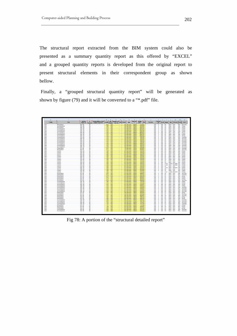
Computer-aided Planning and Building Process
202
The structural report extracted from the BIM system could also be
presented as a summary quantity report as this offered by “EXCEL”
and a grouped quantity reports is developed from the original report to
present structural elements in their correspondent group as shown
bellow.
Finally, a “grouped structural quantity report” will be generated as
shown by figure (79) and it will be converted to a “*.pdf” file.
Fig 78: A portion of the “structural detailed report”

Computer-aided Planning and Building Process
203
Fig 79: Developed “grouped structural quantity report”
6.2.3.2.2 Reinforcement Details and Specifications
Bentley [42] indicates that in addition to automatically extracted
architectural and structural quantity reports, BIM empowers structural
engineers and designers to:
• Develop structural systems for their building with unlimited freedom.

Computer-aided Planning and Building Process
204
• Investigate and study more design options in order to make better design decisions.
• Predict construction costs and building performance prior to actual construction.
However, the proposed BIM system contains no details or specification
within the developed two 3D models (system input) and therefore no
data or specification were extracted from the proposed system.
6.2.3.3 Drawings and Models
It has become evident that designers and architects can benefit from
BIM techniques in terms of drawings production, data storage and
drawings updating. For example, BIM enables a better storage of all
design data within a 3D model of a facility in which 2D plans and
drawings can be automatically generated from this model, including
details and sections. Designers can integrate changes in their design
easily, while drawings and details are updated automatically ensuring
consistency and accuracy of produced drawings and details [36].
Additionally, BIM systems enable designers to focus on their design by
developing 3D models from which presentation drawings and data
reports are easily extracted. Thus, the proposed BIM system produces
architectural and structural drawings, sections and details as required.
However, just as discussed earlier when producing quantity reports,
drawings and models are also produce from two sources (TriForma
architecture and structural), depending on the type of required details.
“MicroStation TriForma Architecture” is responsible for generating
architecture drawings from the system such as section cuts using
“Drawing Extraction Manager” utility, whereas “Triforma Structural”
is responsible for generating all steel drawings, sections and details.

Computer-aided Planning and Building Process
205
Extracting and producing drawings and models from the proposed BIM
system are explained below.
6.2.3.3.1 Architectural Drawings
The process of generating architecture drawings form the system using
“MicroStation TriForma Architecture”, involves the following:-
• defining the “section cutting planes” and
• forward and reflected views and
• the extracted information is processed, resymbolized, and written to a new drawing.
However, the “section plane” is separate and different from the
“forward view plane” and it resymbolized independently from the
forward view planes in drawing extracting. For example, a section cut
of a plan view through a wall looking downward will usually show that
wall in the cut plan while elements such as door swings are shown in
the forward view because the section did not cut through them. In
addition, the extraction of drawings from the BIM required very
complex rules for resymolization to be applied based on part
information (i.e. the appearance of the element can be determined by
the part name of the component). Such things like element thickness or
hatching are controlled by the part’s name of that element as illustrated
in figures (80&81).

Computer-aided Planning and Building Process
206
Fig 80: Architectural produced floor plan and details
Fig 81: Architectural produced drawings (sections & details)

Computer-aided Planning and Building Process
207
6.2.3.3.2 Structural Drawings
Bentley Structural produces a variety of different types of structural
construction drawings such as foundation plans, framing plans,
elevations, sections, and details, etc. Extracting structural drawings
from the BIM system by “MicroStation Structural” is achieved using
the “Drawing Extraction Manager” tool. There the user defines what
levels of a design file to process into a drawing, or define a cut or
forward view distance to show just a specific cross-section of the
design.
However, the structural drawings produced by the proposed BIM
system are controlled by “Bentley Structural” rules which are
established using the “Drawing Resymbolization Rules Manager” and
the “Edit Drawing Resymbolization Rule” dialog boxes. These rules
tell the software how to process the structural data in the extracted
drawings and how or if the structures are labeled. All preferences (how
it is viewed, how the members are drawn, which members appeared in
the drawing) are controlled by the structural rules so a user can go back
and produce the same drawing without having to redefine all the
criteria and settings. For example, beams that are behind another beam
are set by the rules to appear as hidden lines.
6.2.3.3.2.1 Reinforcement Drawings
The BIM system produces an overhead view of the steel section and
vertical detailing sections that include labels for the columns, beams
and girders as shown in figures (82 to 84).
However, these are only a few samples of the variety of drawings the
BIM system is capable off. Though, the BIM system produces
drawings as required full automatically, given the user total freedom in

Computer-aided Planning and Building Process
208
choosing the desire preferences such as color of elements, text
appearance or overall section presentation.
Fig 82: Top steel detailing view

Computer-aided Planning and Building Process
209
Fig 83: Portion of top steel detailing view produced by BIM
Fig 84: A vertical section generated from the BIM

Computer-aided Planning and Building Process
210
6.2.3.3.3 3D Models
3D model presentation is the core of BIM techniques, because visually
rich 3D views are direct presentations of the underlying building
information. In addition, 3D models allow for better understanding and
visually comprehending by viewing several different views of a design
from different angles in a very short time. In fact, older presentation
techniques (usually based on drawings) could not possibly provide
such an exhibition as readily or as effectively. Also, 3D models give
designers and clients the feel of actually walking around a new
building and experiencing a humanistic observation by looking at the
building while standing in front of it.
In this matter, the proposed BIM system offers several 3D models
techniques and tool. However, models can be extracted directly from
the system in MicroStation or combined with Adobe Acrobat, the
proposed BIM system is capable of generating different types of 3D
models for illustrations and visualization as shown in figure (85) which
are produced as “*pdf*” files.
Fig 85: 3D models produced by the BIM within pdf. file

Computer-aided Planning and Building Process
211
7 Discussing the results
It has being said “a picture is worth a thousand words”. Figure (86)
depicted the final picture of the proposed system components and its
end results (system architecture).
Fig 86: Illustrates proposed BIM system architecture
Architectural Model Structural Model
BIM
System Output
System Input
Documentations Visualization
Rendered Photos
Views
Animations
Videos
Pdf. views
Drawings & Models Quantity take-off
Sections
Elevations
Views
Arch.
Report
Plans
3D models
Detail Report Summary Report

Computer-aided Planning and Building Process
212
As already mentioned, this system consists of two 3D models of the
architectural and structural system of the proposed office building. It is
evident from the findings and the picture in figure (86) that the
proposed BIM system has achieved most requirements and tasks
anticipated. Simultaneously, many of these tasks are achieved as easy
as a simple push of a key, especially how accurate and fast producing
the quantity reports were. Traditionally, estimators produce this kind of
reports by digitizing their paper drawings or importing their CAD into
estimate packages or doing manual takeoffs from their drawings which
would take days to accomplish depending on the size of the project.
These methods are prone to human errors, inaccuracy and
inconsistency which can be avoided using BIM systems instead of the
drawings. BIM insures information consistency with the design and
when a change is made to the model, the report is automatically
updated as well as all other associated construction documents and
schedules.
In fact, unlike ordinary CAD systems, BIM is about the information
(B“I”M) that is being gathered in the back during the designing stage
of the 3D models. Now, this is where the “I” in the middle comes to
play, since BIM systems are supposed to build up their database
(information about component of the building) as the 3D model
evolves and develops; however, this knowledge is still not fully
comprehended by the AEC professionals. The development of the “I”
about the 3D model requires a great deal of interference from the
designer and has not been made simple, although this is supposed to be
automatically done as the software developer’s claim.
Practically speaking, there is a lot of effort needed to extract quantity
reports from the BIM, at least when using Bentley’s MicroStation,
which perhaps could be also applied to other BIM applications.
Although these tools promise automation and effortless production of

Computer-aided Planning and Building Process
213
documentation, there is still great deal of human involvement to
achieve data extraction.
In fact, interference with the database and changing it was necessary to
extract documents, reports and drawings, etc. For example, to extract a
simple drawing from the system, the user must be able to access the
system’ database, change and choose the desire requirement including,
line thickness, colors, etc.
7.1.1 Outputs break down
The preceding chart (Fig. 86) illustrates the proposed BIM system
architecture. However, the next diagram (Fig. 87) categorized the
system’s outputs according to the types of produced document which
are:
1) engineering views;
2) quantity reports; and
3) drawings and details.

Computer-aided Planning and Building Process
214
Building Information
Architectural Model
Structural Model
Building Database
Engineering Views
Quantity Reports
Drawings & Details
Fig 87: Categorizing the BIM system outputs

Computer-aided Planning and Building Process
215
7.1.2 Distributing BIM results among targeted disciplines
The final results of the proposed BIM system could also be divided
according to disciplines involved within the AEC industry. In this case,
the system targeted two specific disciplines (architects and structural
engineers) which several documents are possibly produced in
accordance as shown by figures (88 & 89).
7.1.2.1 Results for Architects
Figure (88) below illustrates the type of documents and drawings
architects in general are interested of gaining from the proposed BIM
system. For example, visualization which could be generated at any
stage of the process and expected to be dimensionally consistent in
every view. Most importantly the system enables architects to
visualize the project early in the design stage in order to convey their
design intent, convince a client, or sell the design. Additionally, the
system produces accurate and consistent 2D drawings, 3D models and
estimate reports at any stage of the design.

Computer-aided Planning and Building Process
216
Fig 88: BIM system results for Architects
BIM
Architectural Model Structural Model
System Input
System Output
For Architecture
Visualization Documentations
Drawings & Models
Quantity take-off
Details Rendered Photos
Views
Animations
Simulation
Videos
Arch. Report
Cost Report
Sections
Elevations
Views
Plans
3D models

Computer-aided Planning and Building Process
217
7.1.2.2 Results for Structural Engineers
From the structural model, the system produces accurate and
consistence workshop drawings, details, documents, bills of materials,
and views as requested by the structural engineer as illustrated in figure
(89).
Fig 89: BIM system results for Structural Engineers
BIM
Architectural Model Structural Model
System Input
System Output
For Structural Engineer
Visualization
Drawings & Details
Quantity take-off
Views
Animations
Simulation Struc. Report
Cost Report
Steel Details
Connection Details
Workshop DWG
Documentations

Computer-aided Planning and Building Process
218
7.1.3 Managing Changes and Modifying Process
Since drawings are only reflections of actual and assumed information
which are usually scattered among many drawings with countless
duplicated and conflicting information items, therefore managing these
changes is cumbersome and error prone [81]. Reichardt [82]
acknowledged that BIM is the respond to waste within the AEC
industry which faces challenges because so many diverse players are
involved and because it is difficult to bridge their different information
systems. For example, if a plumber contractor finds a design error that
must be fixed by changing the floor plan, that change may affect other
project participants. Most certainly, this change will cascade wildly
through schedules and budgets, resulting in substantial cost over-runs.
He suggested using BIM technique enables for change proposal to be
reviewed in terms of their implications, with efficient checking by
multiple participants, resulting in both better planning and reducing
expensive mid-construction changes. Also, indicated by Day [83] all
drawings produced by BIM would be views of a single model which
are automatically co-ordinate and if a component, such as a window,
were moved there would be no need to ensure that every drawing
containing that window was changed accordingly.
An example of “how the proposed BIM system can distribute changes
or modifications of design element among associated document?” is
illustrated by figure (90).

Computer-aided Planning and Building Process
219
Fig 90: Illustrates changing or modifying process
Visualization
BIM
Documentatio
Rendered
Views
Animations
Simulation
Videos
A column
modified

Computer-aided Planning and Building Process
220
7.2 Conclusion
The proposed BIM system has illustrated that extracting data and
documents although possible, it is still time consuming process and
difficult to master. In fact, each activity requires a specialist to
perform. For example, rendering a front view of the model involves
several tasks such as, applying materials, textures, lights, etc. which are
not made easy by the software. Also, producing a vertical or horizontal
section from the system requires a great deal of work within the
program’s database to achieve these tasks. In addition, every single
element contained within the model is uniquely represented in the
database, thereby the program needs to identify and execute each
element in order to be included and extracted. Thus, working with the
database is very tedious and requires a great deal of learning, which
raises the question: who is willing or who would pay for this learning
period? Robinson [81] strongly believes that BIM will become the
future way of working, however a new a specialist will have to be
added to the design team who will be responsible for just producing the
BIM data. However, the introduced specialist could be employed
directly by the owner for contract control or by other design team
members. Thus, the cost will be controlled by the model, which will
then be a major interest of the client, quantity surveyor or project cost
control.
Moreover, findings throughout this dissertation suggests that BIM is
most likely to positively impact the way buildings are constructed in
quality and on time completion. However, more research are needed to
fully realized this technology and harvest its benefits. Some thinks,
only time and results will determine whether BIM endorsement will

Computer-aided Planning and Building Process
221
bring collaboration and efficiency to the AEC industry and reduce
project’s cost and delivery time.
In fact, what the AEC industry hopes and what is being thought and
discussed throughout literatures and research, is that information
captured digitally within the BIM system can then be presented as
coordinated documents, be shared across multi disciplines, and serve as
a centralized design management tool. Yet, the ideal system is
anticipated to digitally represent the physical and functional
characteristics of a building and with the help of simulation tools the
system can detect and avoid clashes in a virtual world where
interferences are eliminated before construction ever begins. Indeed,
software vendors and the industry also wish to have BIM serve as a
source for information about a facility forming a database for decisions
making during its life-cycle from inception onward. They also
anticipate BIM systems to include everything related to the building
before construction and to store all building information in one location
which eliminates inconsistency and data overlap that may lead to
expensive construction errors. The aim is to insure that every
participant is working with the same exact information as everyone
else in the project and changes are made to objects only once.
Certainly, as mentioned in the proceeding chapter, achieving BIM
system including all architectural, structural and services objects
information is still far from reality, however figure (91) represents the
ideal BIM system with most common inputs and outputs at least within
the AEC industry. This system contains several models (architecture,
structure, HVAC, MEP, site model, FP model, etc) produced by
different specialized individuals with different levels of details and
different software tools. In addition, this BIM system could be linked
to many other tools and applications (i.e. energy analysis programs,
clashes and interferences detecting programs, performance simulations

Computer-aided Planning and Building Process
222
software, structural optimization programs, etc.) to be the only reliable
basis for decisions during the facility life-cycle from inception onward.
Fig 91: Illustrates a typical BM system architecture

Computer-aided Planning and Building Process
223
8 Overall Conclusions and Recommendations
This dissertation has started with a discussion of computer tools and
applications which for over three decades have played a major role in
the AEC industry and have progressed from being expensive and
highly specialized calculation machines to general-purpose tools
available on every desktop. Although, some of the software on the
market, such as word processors and spreadsheets, are easy to learn and
used productively, CAD packages are challenging and more difficult to
master. This is due to vendors aiming to automate the construction of a
facility form original concept to design and construction to ongoing
operations and maintenance as one process. Unlike other industries,
such as banking and insurance, where many of the tasks are
straightforward and repetitive, in which computers improved
productivity and services; the construction industry, where building
closer to prototypes than mass-produced good, the impact of computers
is much harder to quantify and many agree that new technology has not
been utilized effectively. However, Day [83] points out such
technology can greatly improve the way in which information is
processed and communicated and therefore offers new opportunities.
It promises the automation of construction tasks and activities as well
as blurring the existing boundaries between disciplines and to realize
the aim of creating an integrated database of project information to be
used by all participants.
Thus, the AEC industry is growing rapidly with new project delivery
methodologies are being embraced and designing of facilities is
continuously improving. Additionally, the industry has long sought
techniques and methods to increase productivity and quality, and
reduce project delivery time as well as decreasing overall project cost.

Computer-aided Planning and Building Process
224
However, the overall impression about this industry that it tends to
resist automation; yet the advance of computers and the increase ability
to model buildings using 3D models systems promises to shift that
impression. In fact, the AEC industry involves many teams from
different fields that have a specific role along the facility life cycle.
Each of the teams’ members (architect, engineer or project manager)
contributes to one part of the building completion. Thus, finding ways
to combine theses tasks and improve collaboration and communication
between project teams will lead to improving profitability, reduce cost,
better time management and improved customer/client relationships.
Therefore, 3D and Building information modeling (BIM) offer the
potential to achieve these objectives which hold tremendous promises
for the future of AEC industry and how projects are achieved. It is
believed, the future of the AEC industry is going to be driven by the
use of BIM technology, which acts as a single-source of repository for
information about a building and it aims to integrate every aspect of
that building.
However, the implementation of 3D modeling and BIM in the AEC
industry is inevitable; even though the industry still has to get over
several obstacles and hurdles in order to achieve full 3D virtual
modeling and BIM. One of these obstacles is “how to implement BIM
into AEC firms?” Unlike many other construction practices, currently
there are no clear instructions or roles on “how to implement or use
BIM”, which raise the urgent need to standardize the BIM process and
to define an outline for its implementations. Meaning, a national
standard is required to promote communication across software
platforms to drive adoption and improve collaboration and
communication between stakeholders.
Also, the AEC industry participants are concern regarding, who should
develop and operate the building information and how the cost of

Computer-aided Planning and Building Process
225
development and operational costs is distributed? “If all can
contribute, who should lead and who is responsible for failure?” [76]
Therefore, control over the BIM model raises the question: who owns
and maintains the model? In addition to legal and risk management
issues earlier discussed.
Another major concern is related to the ability of BIM software to
exchange information with other computer applications
(interoperability). While the benefit of BIM and 3D modeling are well
established and more firms are using BIM, each member of the
project’s team tends to have their own tool which cannot be integrated
with the others, resulting in duplication of information and poor
communication. Therefore, a common set of standards must be
established and implemented by all software vendors in the industry to
allow for better communications and to improve data exchange ability.
8.1 Recommendations
Although, the use of BIM is expected to continue to increase in the
AEC industry, AEC stakeholders and researchers have to develop
suitable solutions to overcome challenges and obstacles [66]. In
addition to standardization issues, some key aspects that will impact
the future of BIM endorsement are:
BIM education and training: the recent evolution of BIM software and
its endorsement among the AEC industry suggests that BIM holds
tremendous promises for the future of buildings and therefore, it must
be introduced to students at educational institutes [77]. In addition, the
benefits to students must be researched and evaluated to give them the
best opportunity for future employment. Moreover, implementing BIM
takes effort and demands careful planning, and a significant amount of

Computer-aided Planning and Building Process
226
education and training for all project participants. They must be
informed regarding benefits BIM can bring to both the project and the
construction team as well as trained in the new workflow [23].
Real world case studies: Quantifying the impact of a BIM approach
through real world construction case studies will offer a more
compelling argument for BIM adoption by the AEC industry [78].
Establishing database of knowledge: there is a need to establish a
source (database) with knowledge and experience in the use and
practices of BIM to be available for potential BIM users.
Research in BIM: investment in the research and development in
building information modeling will greatly benefit the AEC industry.
As the use of BIM is expected to improve collaboration and
communication between project teams which will lead to improving
profitability, reduce cost, better time management and improved
customer/client relationships.

9 References and Bibliography
[1]. Young Jr. N. W., Jones S.A., and Bernstein H.M.(2007) Interoperability in the Construction Industry: SmartMarket Report. [online] Available from: http://construction.ecnext.com/mcgraw_hill/includes/SMRI.pdf [accessed 15 October 2008].
[2]. Kymmell, W. (2008) Building Information Modeling: planning and managing construction projects with 4D CAD and simulations. USA: MaGraw Hill.
[3]. Kato, N., Okano, A. and Okuno, T. (1999) Modeling Virtual Cities Using Genetic Algorithms. 1999 IEEE MidnightSun Workshop on Soft Computing Methods in Industrial Applications. Kuusamo, Finland, June 1618, 1999. [online]. Available from: http://ieeexplore.ieee.org/stamp/stamp.jsp?arnumber=00782722 [accessed 22 October 2008].
[4]. Dodge, M. , Smith, A. and Doyle S. (1997) Virtual Cities on the WorldWide Web: Towards a Virtual City Information System. [online]. Available from: http://www.casa.ucl.ac.uk/martin /virtual_cities.html [accessed 10 October 2008].
[5]. Batty, M., Chapman, D., Dale, P., Densham, P., and Harley, I. (2006) Virtual London: A proposal. [online]. Available from: http://www.casa.ucl.ac.uk/vl.html. [accessed 14 March 2006].
[6]. Franklin, R., Heesom, D. and Felton, A. (2006) A Critical Review of Virtual Reality and Geographical Information Systems for Management of the Built Environment. Proceeding of the Information Visualization (IV’06), July 572006, London, England: IEEE computer Society Press.
[7]. Bourdakis. Virtual Reality: A communication tool for Urban Planning. Bath, UK: Centre of Advanced Studies in Architecture: University of Bath. [Online]. Available from: http://fos.prd.uth.gr/vas/papers/CAADTNDC/ [accessed on 22 October 2008].
[8]. Croser, J. (2006) MicroStation Connects to Google Earth Tools. BE magazine [online], 3(1),pp.2224. Available from: http://www.nxtbook.com/nxtbooks/bemagazine/vol3issue1/ [accessed 1 July 2008].

[9]. Czermuszenko, M., Pape, D., Sandin,D., DeFanti, T., Dawe, G.L., and Brown, M.D. (1997) The ImmersaDesk and Infinity Wall ProjectionBased Virtual Reality Displays. Computer Graphics. Available from: http://www.evl.uic.edu/pape/CAVE/idesk/ paper/ (accessed 4 June 2007).
[10]. Karp, R and Quinn, B. (2004) Computer Aided Design More than Just an Electronic Pencil and Paper. Structure magazine [online] July 2004. Available from: www.structuremag.Org /Old Archives/2004/july/The%20Power.pdf [accessed 8 April 2008].
[11]. Demchak, G., Dzambazova, T. and Krygiel, E. (2008) Introducing REVIT® Architecture 2009: BIM for Beginners. Canada:Wiley.
[12]. Faulkner, L. (2006) Interoperability for the Steel Industry. Structure magazine [online], November 2006, page 18. Available from: http://www.structuremag.org/archives/2006/ February2006/CTechnologyFeb06.pdf [accessed 26 March 2008].
[13]. Smith, D. (2007). An Introduction to Building Information Modeling (BIM). Journal of Building Information Modeling (JBIM) [online], Fall 2007. Available from: http://www.wbdg.org/pdfs/jbim_fall07.pdf [Accessed 23 July 2008].
[14]. Laasonen, M., and Karlakari, T. (2006) Maintaining data in building modelbased facility management system. Symposium, Changing user demands on buildings, edited by Haugen, T.I., Moun, A. , Bröcher, J. , Norwegian University of Science and Technology, Trondheim, 2006 .pp.306316. Available from: http://www.tut.fi/units/rka/rtt/tutkimus/rakennusmittaus/CIBW70_2006_ Model_to_FM.pdf (accessed 20 January 2008).
[15]. See, R. (2007). Building Information Models and Model Views. Journal of Building Information Modeling (JBIM) [online], Fall 2007. Available from: http://www.wbdg.org/pdfs/jbim_fall07 .pdf [Accessed 23 July 2008].
[16]. Erger K. (2007) The Rewards and Risks of BIM [online], Available from: http://karenerger.com/Documents/BIM%20Risks%20and %20Rewards.doc. [accessed 24 September 2007].
[17]. Smith, D. K. and Edgar, A. (2007). Building Information Models (BIM). WBDG (Whole Building Design Guide). www.wbdg.org/resources/bim [updated 07092007 accessed 18 January 2008].

[18]. DeStefano, J (2007) Computer Technology in the Practice of Structural Engineering [online], Structure magazine May 2007. Available from: http://www.structuremag.org/Archives/20075/CTechnology%20%20DeStefanoMay07.pdf [accessed 27 March 2008].
[19]. Kennetts, E (2006) National Building Information Model Standards Committee Formed New NIBS Group Will Create U.S. BIM Standard. National Institute of Building Science. Available from: http://www.nibs.org/newsstory1.html [updated 2008 accessed 19 January 2008].
[20]. Autodesk (2007) REVIT building information modelling. BIM in Action [online], Available from: http://images.autodesk.com/latin_am_main/files/Revit_BIM_Oculus_CAD_Mgr_Jun05.pdf [accessed 24 September 2007].
[21]. Brucker B. A., Case, M. P., East, E. W. Huston, B. K., Nachtigall, S. D., Shockley, J. C., Spangler, S. C. and Wilson, J. T. (2006) Building Information Modeling (BIM): ARoad Map for Implementation To Support MILCON Transformation and Civil Works Projects within the U.S. Army Corps of Engineers [online], Available from: https://cadbim.usace.army.mil/MyFiles/ERDC_ TR0610.pdf [accessed on 12 September 2007].
[22]. Autodesd Revit whit paper (2005) Building information Modeling for Sustainable Design [online] Available from: http://www.ddscad.com/BIM___Sustainable_Design.pdf [accessed on 7 September 2007].
[23]. Cyon Research (2003) The Building Information Model: A Look at Graphisoft’s Virtual Building Concept [online], Bethesda, USA. Cyon Research Corporation. Available from: http://wbh.com/WhitePapers/Graphisoft_Virtual_Building_Modela_Cyon_Research_White_Paper_030102.pdf [accessed on 12 May 2005].
[24]. Industry Directions (2006) Leveraging the Value Chain in Construction Building information Modeling [online]. Available from: http://www304.ibm.com/jct03004c/tools/cpeportal/ fileserve/download1/41842/Construction.pdf?contentid=41842 [accessed 28 March 2008]
[25]. Turner, B. (2005) Integrate Design with Construction and Operating Costs Using BIM. The American Institute of Architects (AIA). Available from: http://www.aia.org/k_a_200612_ftr (updated 2007, accessed 24 September 2007).
[26]. Autodesk (2007) BIM in Action [online] Available from: http://www.therightangle.ie/Uploads/product_data/revit%20 architecture%202008/revit_bim_in_action_jan07.pdf [accessed 24 September 2007].
[27]. Yoders, J. (2006). The Merry Road to BIM. Building Design and Construction [online]. Available from: http://www.bdcnetwor .com/article/CA6354606.html?industryid=42772&q=jeff+yoders%2C+the+merry+road+to+bim [accessed 27 March 2008].
[28]. Rocha, L. (2003) Comprehensive Building Modelling. Architecture Week: Page T1.1. 25 June 2003. online]. Available from: http://www.architectureweek.com/2003/0625/tools_11.html (accessed 15 January 2008).
[29]. Dossick, C. S. (2006) Building Information Modeling (BIM) – Fully Integrated and Automated Project process (FIAPP) [online]. Available from: http://faculty.washington.edu/cdossick/ research.shtml [updated 8 March 2006, accessed 24 September 2007].
[30]. Williams, PE. S. D., (2007) Construction Document Changes to Improve Constructability. National Conference on Building Commissioning: May 24, 2007. Available from: http://www.peci.org/ncbc/proceedings/2007/Williams_NCBC2007.pdf> (accessed 15 January 2008).
[31]. Autodesk (2003) Building Information Modeling: A Key to PerformanceBased Design [online], Available from: http://images.autodesk.com/adsk/files/bim_a_key_to_performancebased_design.pdf [accessed 24 September 2007].
[32]. Huell, E., (2006) Building Information Modeling: Collaboration, Integration, and Interoperability. U.S. Army Corps Engineers. The CAD/BIM Technology Centre Available from: https://cadbim.usace.army.mil/MyFiles/EdwardHuellBIM_FINAL.pdf > (accessed on 12 September 2007).
[33]. Matta, C., Kam, C., Clevenger, C., Ho P. (2006). GSA’s National 3D4DBIM Program. [online] Available from: http://www7 .nationalacademies.org/ffc/2calvin_kam_gsa.pdf (accessed 15 January 2008).
[34]. Harris, D. A. (2007) Message from NIBS “This new and significant journal will be an essential information source on business, standards and technical issues related to Building Information Modeling.” Journal of Building Information Modeling, (Fall 2007), Available from: http://www.wbdg.org/pdfs/jbim_fall07 .pdf (accessed 17 June 2008).

[35]. East, E. W. (2007). BIM for Construction Handover. Journal of Building Information Modeling (JBIM) [online], Fall 2007. Available from: http://www.wbdg.org/pdfs/jbim_fall07.pdf [Accessed 23 July 2008].
[36]. Hartmann, T. and Fischer, M. (2008). Application of BIM and Hurdles for Widespread Adoption of BIM. 2007 AISCACCL eConstruction Roundtable Event Report. CIFE Working Paper #WP105. Revised – FEBRUARY 2008. Stanford University. Available from: http://cife.stanford.edu/online.publications /WP105.pdf [accessed 30 July 2008].
[37]. Edgar, A. (2008) Building Value through Building Information Innovation. Journal of Building Information Modeling (JBIM) [online], Spring 2008. Available from: http://www.wbdg.org /pdfs/jbim_spring08.pdf [Accessed 23 July 2008].
[38]. Bernstein and Pittman (2005) Barriers to the adoption of Building Information Modeling in the Building Industry. Autodesk building solutions white paper. [online] Available from: http://images.autodesk.com/adsk/files/bim_barriers_wp_mar05.pdf[accessed 19 January 2009].
[39]. NIST (2004) Cost Analysis of Inadequate Interoperability in the U.S. Capital Facilities Industry. U.S. Department of Commerce. National Institute of Standards and Technology. Available from: http://www.bfrl.nist.gov/oae/publications/gcrs/04867.pdf [accessed 24 October 2008]
[40]. Howard, R and Bjork, B. (2003) Building information models – experts’ views on BIM/IFC developments. [online] Available from: http://itc.scix.net/data/works/att/w782007007043Howard.pdf [accessed 7 February 2008]
[41]. NavisWorks (2008) Working together you can achieve more with JetStream[online] Available from: http://navisworks.com/de [accessed on 4 June 2008]
[42]. Bentley (2008) MicroStation Platform Technology and Products [online] Available from: http://www.bentley.com/enUS/Products/MicroStation+Product+Line/ [accessed on 22 April 2008].
[43]. VICOsoftware (2008) Vico software: Integrating Construction. [online] Available from: http://www.vicosoftware.com/ [accessed 10 October 2008].
[44]. Nemetschek (2008) “Home page”. [online] Available from: http://www.allplan.com/en/home.html [accessed 10 October 2008].
[45]. 4BIM (2007) 4BIM discussion [home page] http://www.4bim.com/ (accessed on 17 November 2005).
[46]. Halfawy, M. and Froese, T. (2005) Integration of data and processes of AEC projects using the industry foundation classes. 6th Construction Specialty Conference, Toronto, Ont., June 24, 2005, pp. 110.
[47]. Howell, I and Batcheler, B. (2005) Building information Modeling Two Year Later – Huge Potential, Some Success and Several Limitations. [online] Available from: http://www.laiserin.com /features/bim/newforma_bim.pdf [accessed June 2008].
[48]. Autodesk (2005) Parametric Building Modeling: BIM’s Foundation [online] Available from: www.ideateinc.com/whitepapers/all /Revit%20Parametric%20Building%20Modeling%20 Foundation .pdf> (accessed 2 June 2008).
[49]. Eastman C., Teicholz P., Sacks R., and Liston K. (2008) BIM Handbook: A Guide to Building Information Modeling for Owners, Engineers, and Contractors. New Jersey: John Wiley & Sons, Inc
[50]. Edgar, A. (2007) “The Committee recognizes that this is a deceptively simple concept requiring a great deal of cooperation for the good of all and, for this reason, frequent and open communication is a key success factor, ” Journal of Building Information Modeling (JBIM) [online], (Fall 2007), Available from: http://www.wbdg.org/pdfs/jbim_fall07.pdf [Accessed 17 June 2008].
[51]. SOLIBRI (2008). The World Leader in Design Spell Checking. [online], Available from: http://www.solibri.com/buildinginformationmodeling/ifcandbim.html [accessed 17 January 2008].
[52]. Vectorworks (2008) Nemetschek North America Announces Public Beta for Upcoming IFC Version 2x3 Plugins and GSAcompliant Space Object. [online], Available from: http://www.nemetschek.net/news/pressreleases/2007/041807.php [accessed 18 January 2008].

[53]. Wikipedia (2008) The world free encyclopedia [online], Available from: http://en.wikipedia.org/wiki/Industry_Foundation_Classes [accessed 21 January 2008]
[54]. BE Magazine (2005)Building Design Reflects Dynamic Stability, Architectural firm’s use of 3D model cuts design time in half, improves accuracy [online], BE magazine, volume 3, Issue 1. Available from: http://www.nxtbook.com/nxtbooks/bemagazine /vol3issue1/index.php [accessed 19 January 2008]
[55]. Al‐Charieh, K. (2008) 3D‐Labour: TU Berlin. www.math.tuberlin.de/3dlabor. Personal interview.
[56]. Yoders, J. (2007) Acrobat 3D 8 makes 3D/CAD filesharing easier [online]. Building Design and Construction. [online] Available from: http://www.bdcnetwork.com/article/CA6466254.html [accessed 14 July 2008].
[57]. Flynn, J. (2005) Rendering with MicroStation, Exton, USA: Bentley Institute Press; 2005. 413p.
[58]. Bentley (2009) A Source of Innovation, a CAD Platform for Integration [online] Available from: www.bentley.com/enUS/ Products/MicroStation/Interactive+3D+PDF.htm [accessed on 12 February 2009].
[59]. Market Wire (2008) "Resolving Risk Issues Key to Widespread Adoption of BIM". Market Wire. May 2008. FindArticles.com. 28 Jul. 2008. [online] Available from: http://findarticles.com/p/ articles/mipwwi/is_200805/ai_n25415885. [accessed 25 April 2009].
[60]. AIA (The American Institute of Architects) (2007). 2007 AIA Digital Practice Documents. [online] Available from: http:// www.aia.org/SiteObjects/files/2007%20Digital%20Practice%20Documents.pdf [accessed 28 July 2008]
[61]. BE Magazine (2006) [online] 2006 BE Award Winner. A Marriage of Science and Nature. BIM saves months off timeline during design of sixstory hospital in parklike setting [online], BE magazine, volume 3, Issue 4. Available from: http:// www.nxtbook.com/nxtbooks/bemagazine/vol3issue4/ [accessed 1 July 2008]
[62]. SIAP (2003) Society of Iranian Architects & Planners. Bam: Killer Earthquake. [online] Available from: http://www.siap.org/ News/BamEQ2003/BamEQ2003.htm [accessed 7 February 2008].

[63]. Smilow, J (2007) Practical BIM. How are engineers and architects implementing and using the developing technology? Modern Steel Construction (November 2007). [online] Available from: http://www.modernsteel.com/Uploads/Issues/November_2007/112007_30771_WSP_cantor_web.pdf [accessed 20 January 2009].
[64]. Howard, R. and Bjork, B. (2007) Building Information Models – Experts’ view on BIM/IFC developments. ITC Digital Library. [online] Available from: http://itc.scix.net/data/works/att/w 782007007043Howard.pdf [accessed 20 January 2009].
[65]. Bacon, S. (2008) BIM Crosses Boundaries at SeattleArea High Rise. Structural magazine [online] January 2008. Available from: http://www.structuremag.org/Archives/20081/SFBIMHyattHotelBaconJan08.pdf [accessed 26 January 2009]
[66]. Azhar S., Nadeem, A., Mok, J.Y.N., Leung, B.H.Y (2008) Building Information Modeling (BIM): A New Paradigm for Visual Interactive Modeling and Simulation for Construction Projects. First International Conference on Construction in Developing Countries (ICCIDC1) “Advancing and Integrating Construction Education, Research & Practice” August 45, 2008, Karachi, Pakistan. [online] Available from: http://www.neduet.edu .pk/ICCIDCI/Conference%20Proceedings/Papers/045.pdf [accessed 28 January 2009].
[67]. Wyatt, G. (2007) Maintaining BIM Integrity in the Structural Engineering Office. AutodeskREVIT® STRUCTURE. [online] Available from: http://images.autodesk.com/adsk/files/ maintaining_bim_integrity_in_structural_engineering_office.pdf [accessed on 28 January 2009].
[68] Condon, T. (2006) Building Information Modeling. This approach to project documentation has the potential to synthesize the entire life cycle of a facility. Today’s Facility Manager, (November 2006) [online] Available from: http://www.todaysfacility manager.com/tfm_06_11_factech.php [accessed on 28 January 2009].
[69]. Khemlani, L. (2006) Use of BIM by Facility Owners: An “Expotitions” Meeting. AECbytes “Building the Future. (May 16, 2006) [online] Available from: http://www.aecbytes.com /buildingthefuture/2006/Expotitions_meeting.html [accessed on 28 January 2009].

[70]. AGC (2005) the Contractors’ Guide to BIM, 1st ed. The Associated General Contractors of America. [online] Available from: http://www.agcnebuilders.com/documents/BIMGuide.pdf [accessed on 29 January 2009].
[71]. Goldberg, E. (2006) AEC From the Ground UpState of the AEC Industry 2006. BIM solutions are changing the AEC landscape. Cadalyst, May 1, 2006 [online] Available from: http://aec.cadalyst.com/aec/article/articleDetail.jsp?id=324995 [accessed on 31 January 2009].
[72]. Goldberg, E. (2005) AEC From the Ground UpState of the AEC Industry. BIM implementation slow, but inevitable. Cadalyst, May 1, 2005 [online] Available from: http://aec.cadalyst.com /aec/article/articleDetail.jsp?id=161716 [accessed 31 January 2009].
[73]. Azhar, S., Hein, M., Sketo, B. (2008) Building Information Modeling (BIM): Benefits, Risks and Challenges. [online] Available from: https://fp.auburn.edu/heinmic/Pubs/ASC%202008BIM%20Benefits.pdf [accessed 31 January 2009].
[74]. Kunz, J. , Gilligan, B. (2007) Value from VDC / BIM Use: Survey Results. Center for Integrated Facility Engineering (CIFE) Stanford University, 6 November 2007 [online] Available from: http://cife.stanford.edu/VDCSurvey.pdf [accessed on 31 January 2009].
[75]. Khemlani, L. (2007) Top Criteria for BIM solutions: AECbytes Survey Results. AECbyets, October 10, 2007. [online] Available from: www.aecbytes.com/feature/2007/BIMSurveyReport.html [accessed 31 January 2009].
[76]. Thomson, D. (2001) The construction law briefing paper. [online] Available from: http://www.minnlaw.com/Articles/68553.pdf [accessed 9 February 2009].
[77]. Taylor, J. M., Liu, J. , Hein, M. F. (2008) Integration of Building Information Modeling (BIM) into an ACCE Accredited Construction Management Curriculum. [online] Available from: https://fp.auburn.edu/heinmic/Pubs/ASC%202008Integration .pdf [accessed 10 February 2009].
[78]. Suermann, P.C., Issa, R. R.A. (2007) Evaluating the Impact of Building Information Modeling (BIM) on Construction. 7th International Conference on Construction Applications of Virtual Reality: October 2223, 2007. [online] Available from: http://www.engr.psu.edu/convr/proceedings/papers/22_Suermann_submission_47.pdf [accessed on 10 February 2009].

[79]. AECbytes “Building the Future”. (2005) The CIS/2 Format: Another AEC Interoperability Standard [online] Available from: www.aecbytes.com/buildingthefuture/2005/CIS2format.html [Accessed 29 January 2009]
[80]. Hartmann, T., Goodrich, W.E., Fischer, M., Ederhard, D. (2007) Fulton Street Transit Center Project: 3D/4D Model Application Report. CIFE Technical Report #TR170, May 2007: Stanford University. [online] Available from: http://cife.stanford.edu /online.publications/TR170.pdf [Accessed 17 July 2008]
[81]. Robinson, C. (2007) Structural BIM: Discussion, case studies and latest developments. The Structural Design of Tall and Special Buildings [online] December 2007; 16(4): 519533. Available from: www3.interscience.wiley.com/cgibin/fulltext/11683353 8/PDFSTART [Accessed 15 April 2009].
[82]. Reichardt, M. (2008) CAD, Geospatial, 3D and BIM Standards Converge. GIS Dvelopment: The Global Geospatial Magazine [online] April 2008. Available from: www.gisdevelopment.net /magazine/glob al/2008/april/56.htm. Accessed 2009 April 20.
[83]. Day A (1997) Digital Building. Oxford: Laxton’s:168p.
[84]. Parish, Y. I. H., Müller P. (2001) Procedural Modeling of Cities. ACM SIGGRAPH [online] 1217 August 2001; Los Angeles, CA, USA. Available from: http://graphics.ethz.ch/Downloads/Publi cations/Papers/2001/p_Par01.pdf [Accessed 23 April 2009].
[85]. Wingly, S. (2005) CAVE as CritSpace: A single Display Croupware Application on Virtual Environment. CAAD Futures: learning from the Past. Special publication of papers presented at the CAAD futures 2005 conference held at the Vienna University of Technology, Vienna, Austria: June 2025, 2005.
[86]. Whyte, J. (2002) Virtual Reality and the Built Environment. UK: Architecture Press.
[87]. Birx, G. W. (2006) BIM Creates Change and Opportunity. Adapted from an article originally published in AIArchitect [online] October 2006. Available from: http://www.aia.org/aiaucmp/groups/ek_members/documents/pdf/aiap016610.pdf [Accessed 1 May 2009].
[88]. Brucker, B. (2009) Building Information Modeling to Benefit Entire Facility Life Cycle [online] Available from: http://www.cecer.army.mil/td/tips/docs/BIMLC.pdf [accessed 4 May 2009].

[89]. buildingSmartalliance (2009) United States National CAD Standard [home page] Available from: www.buildingsmartalliance.org/ncs/ [accessed 4 May 2009].
[90]. National Institute of Building Science (2009) New Version of the United States National CAD Standard® Now Available [home page] Available from: http://www.nibs.org/newsstory1.html [accessed 4 May 2009]
[91]. East, E. W. (2007) Construction Operations Building Information Exchange (COBIE) Requirements Definition and Pilot Implementation Standard. US Army Corps of Engineers: Engineering Research Center [online] Available from: http://www.dtic.mil/cgibin/GetTRDoc?AD=ADA491932& Location=U2&doc=GetTRDoc.pdf [accessed 5 May 2009]


10 List of Figures
Fig 1: Exporting and importing process between proposed applications .................... 24
Fig 2: MicroStation arch behaves differently in “Nemetschek Allplan” ..................... 28
Fig 3: Illustrates lost of hatching in Nemetschek Allplan ............................................ 29
Fig 4: Texts and notes exported from MS disappeared in “Allplan”. .......................... 30
Fig 5: Annotation elements lost their associated text in Allplan (right). ..................... 31
Fig 6: Spline does not look as smooth in Arch. Desktop 3.3 ....................................... 34
Fig 7: Circle does not look as smooth in Arch. 3.3 ...................................................... 35
Fig 8: The two cylinders are attached in Arch. Desktop 3.3 ........................................ 36
Fig 9: Cylinders (sold & surface) look the same when rendered in Arch. 3.3 ............. 37
Fig 10: “circular filleted” and “chamfered corners” differ in Arch. 3.3 ...................... 38
Fig 11: Sold slab behaves differently in Arch. 3.3 ....................................................... 39
Fig 12: Shows sphere’s different appearance in Arch. 3.3 ........................................... 40
Fig 13: Arch. 3.3 represents “Cones” wiremesh differently ........................................ 41
Fig 14: Illustrates lost of dimension association in Arch. 3.3 ...................................... 45
Fig 15: Illustrates the difference in Spline appearance ................................................ 45
Fig 16: Shows extra information on top of each element in Ms .................................. 46
Fig 17: Symbols from Allplan are represented by numbers ......................................... 47
Fig 18: Spline with connection appeared differently in MicroStation ......................... 47
Fig 19: Barcode looks different in MicroStation ......................................................... 48
Fig 20: Automatic dimensioning association and accuracy problems ......................... 49
Fig 21: Stairs exported from Allplan to MS included hiding information ................... 50
Fig 22: “Allplan” wall unit accepts “Arch. 3.3” rendering command ......................... 54

Fig 23: illustrates the difference in wall unit at bottom ............................................... 54
Fig 24: Nemetschek Allplan “Spline” works as one unit ............................................. 55
Fig 25: Arch. 3.3 “Spline” behaves as separate elements and modified differently .... 55
Fig 26: Shows the difference in braces at bottom ........................................................ 56
Fig 27: Extra information introduced in all views in “Arch.3.3” ................................. 56
Fig 28: Extra data and falls “wiremesh” presentation of elements. ............................. 57
Fig 29: Sphere imported from Arch.3.3 to MS in different stages .............................. 59
Fig 30: 3D shapes falsely represented and did not render in MicroStation. ................ 60
Fig 31: Hatching imported from Arch.3.3 to Allplan look different. .......................... 62
Fig 32: Illustrates the loss of hatching association. ...................................................... 63
Fig 33: Arch. 3.3 Spline is modified differently in Nemetschek Allplan .................... 63
Fig 34: “Architectural Desktop” 3D elements cannot be rendered by “Allplan” ........ 64
Fig 35: Examples of Virtual Cities on the WWW ....................................................... 71
Fig 36: A small section of 2D plan of Hashtgerd Newtown ........................................ 73
Fig 37: 2D section of Hashtgerd after eliminating extra information .......................... 74
Fig 38: A photo image of Hashtgerd Newtown ........................................................... 75
Fig 39: the full developed 2D plan of the VRCE ......................................................... 76
Fig 40: 2D CAD plan of the Hashtgerd New Town..................................................... 77
Fig 41: 3D models as placed to form the VRCE .......................................................... 79
Fig 42: Simple 3D models developed differently to form VREC ................................ 80
Fig 43: The CAVE (Cave Automatic Virtual Environment) ....................................... 82
Fig 44: Screen shots of visit to the TU portal .............................................................. 83
Fig 45: A sample of the images created along the walkthrough path .......................... 85
Fig 46: Showed snap shots of VRCE video ................................................................. 86
Fig 47: Illustrates the process of exporting the VRCE to Google Earth ...................... 89

Fig 48: Hashtgerd location as presented by Google Earth ........................................... 90
Fig 49: 2D plan of Hashtgerd as placed on Google Earth ............................................ 91
Fig 50: Visualizing the VRCE in Google Earth ........................................................... 93
Fig 51: Visualizing detailed VRCE Models by Google Earth ..................................... 94
Fig 52: layers and associated data exported to Google earth ....................................... 96
Fig 53: The “IFC-mBomb” project model diagram ................................................... 119
Fig 54: Single BIM (x1) ............................................................................................ 138
Fig 55: BIM (x2) ........................................................................................................ 138
Fig 56: BIM (x3) ....................................................................................................... 139
Fig 57: Multiple BIM ................................................................................................. 140
Fig 58: COBIE process overview .............................................................................. 154
Fig 59: Military Barracks BIM Model (USACE Honolulu District) ........................ 156
Fig 60: Fort Lewis Barracks, Seattle District ............................................................. 156
Fig 61: SBA Group new innovative office building (Vilnius, Lithuania) .................. 158
Fig 62: Computer generated image showing the steel frame (red) ............................ 161
Fig 63: Addition to the existing Denver Art Museum ............................................... 162
Fig 64: Park Hospital in Novi, Michigan ................................................................... 163
Fig 65: BIM consists of architectural, structural and MEP system ........................... 165
Fig 66: BIM of One Island East (OIE) Project.......................................................... 166
Fig 67: 3D structural model ...................................................................................... 177
Fig 68: 3D architectural model ................................................................................. 178
Fig 69: Proposed BIM system Chart .......................................................................... 179
Fig 70: A sample of rendered photos produced by the BIM system .......................... 183
Fig 71: Screen shots of the “wiremesh-model” video ................................................ 184
Fig 72: Screen shots of the “ray trace” video of the office building .......................... 184
Fig 73: Views of the office model in Google Earth environment .............................. 189
Fig 74: The BIM is inserted in Acrobat as “pdf” file ................................................. 192
Fig 75: Portion of the “architectural detailed report”................................................. 198
Fig 76: Architectural Summarized quantity report .................................................... 199
Fig 77: “grouped architectural quantity report” ......................................................... 200
Fig 78: A portion of the “structural detailed report” .................................................. 202
Fig 79: Developed “grouped structural quantity report” ........................................... 203
Fig 80: Architectural produced floor plan and details ............................................... 206
Fig 81: Architectural produced drawings (sections & details) ................................... 206
Fig 82: Top steel detailing view ................................................................................. 208
Fig 83: Portion of top steel detailing view produced by BIM .................................... 209
Fig 84: A vertical section generated from the BIM ................................................... 209
Fig 85: 3D models produced by the BIM within pdf. file .......................................... 210
Fig 86: Illustrates proposed BIM system architecture ............................................... 211
Fig 87: Categorizing the BIM system outputs ........................................................... 214
Fig 88: BIM system results for Architects ................................................................. 216
Fig 89: BIM system results for Structural Engineers ................................................. 217
Fig 90: Illustrates changing or modifying process ..................................................... 219
Fig 91: Illustrates a typical BM system architecture .................................................. 222

11 List of Tables
Table (1) Exporting elements from MicroStation to Nemetschek Allplan .................. 27
Table (2) Exporting elements from MicroStation to Arch. Desktop 3.3 ...................... 33
Table (3) Exporting elements from Nemetschek Allplan to MicroStation .................. 44
Table (4) Exporting elements from Nemetschek Allplan to Arch.3.3 ......................... 53
Table (5) Exporting elements from Arch.3.3 to MicroStation V8 ............................... 58
Table (6) Exporting elements form Arch. 3.3 to Nemetschek Allplan ........................ 61