COMPUTATIONAL FLUID DYNAMICS MODELING PATTERNS …
11
Song, Y., et al.: Computational Fluid Dynamics Modeling Patterns and Force ... THERMAL SCIENCE: Year 2017, Vol. 21, No. 6A, pp. 2553-2563 2553 COMPUTATIONAL FLUID DYNAMICS MODELING PATTERNS AND FORCE CHARACTERISTICS OF FLOW OVER IN-LINE FOUR SQUARE CYLINDERS by Yidan SONG a,b , Rui ZHU a , Terrence W. SIMON b , and Gongnan XIE a * a Department of Mechanical and Power Engineering, School of Marine Science and Technology, Northwestern Polytechnical University, Xi’an, China b Department of Mechanical Engineering, University of Minnesota, Minneapolis, Minn., USA Original scientific paper https://doi.org/10.2298/TSCI170211035S The flow over four square cylinders in an in-line, square arrangement was nu- merically investigated by using the finite volume method with CFD techniques. The working fluid is an incompressible ideal gas. The length of the sides of the array, L, is equal. The analysis is carried out for a Reynolds number of 300, with center-to-center distance ratios, L/D, ranging from 1.5 to 8.0. To fully understand the flow mechanism, details in terms of lift and drag coefficients and Strouhal numbers of the unsteady wake frequencies are analyzed, and the vortex shedding patterns around the four square cylinders are described. It is concluded that L/D has important effects on the drag and lift coefficients, vortex shedding frequencies, and flow field characteristics. Key words: four square cylinders, flow patterns, drag coefficients, lift coefficients, Strouhal numbers, CFD Introduction Flow past multiple bluff bodies has become an active research topic in recent years. Examples can be found in numerous engineering applications, such as offshore platforms, pow- er generators, cooling towers, heat exchanger tubes, bridge piers, chimney stacks, and so on. Investigation of the flow past a group of cylinders can provide better understanding of fluid characteristics, such as vortex patterns, pressure distributions and body forces, which are im- portant for engineering design practice. To date, there are a number of experimental and numerical studies published for de- scribing fluid flow over single or two cylinders. Sumner [1] reviewed recent studies with two circular cylinders of equal diameter in different arrangements immersed in a steady cross-flow. He primarily focused on the near-wake flow patterns, Reynolds number effects, intermediate wake structure, and the general trends in the measurements of the aerodynamic force coeffi- cients and Strouhal numbers. Han et al. [2] investigated the flow past two circular cylinders in a tandem arrangement utilizing spectral element methods in which the Reynolds number was chosen as 200. The results show three wake flow patterns, which are determined by spac- ing ratios. Forces are highly depended on flow patterns. One paper of Mittal and Kumar [3] researched incompressible flow past two cylinders in tandem and staggered arrangements at * Corresponding author, e-mail: [email protected]
Transcript of COMPUTATIONAL FLUID DYNAMICS MODELING PATTERNS …

Song, Y., et al.: Computational Fluid Dynamics Modeling Patterns and Force ... THERMAL SCIENCE: Year 2017, Vol. 21, No. 6A, pp. 2553-2563 2553
COMPUTATIONAL FLUID DYNAMICS MODELING PATTERNS AND FORCE CHARACTERISTICS OF FLOW OVER IN-LINE
FOUR SQUARE CYLINDERS
by
Yidan SONG a,b, Rui ZHU a, Terrence W. SIMON b, and Gongnan XIE a*
a Department of Mechanical and Power Engineering, School of Marine Science and Technology, Northwestern Polytechnical University, Xi’an, China
b Department of Mechanical Engineering, University of Minnesota, Minneapolis, Minn., USA
Original scientific paper https://doi.org/10.2298/TSCI170211035S
The flow over four square cylinders in an in-line, square arrangement was nu-merically investigated by using the finite volume method with CFD techniques. The working fluid is an incompressible ideal gas. The length of the sides of the array, L, is equal. The analysis is carried out for a Reynolds number of 300, with center-to-center distance ratios, L/D, ranging from 1.5 to 8.0. To fully understand the flow mechanism, details in terms of lift and drag coefficients and Strouhal numbers of the unsteady wake frequencies are analyzed, and the vortex shedding patterns around the four square cylinders are described. It is concluded that L/D has important effects on the drag and lift coefficients, vortex shedding frequencies, and flow field characteristics.Key words: four square cylinders, flow patterns, drag coefficients,
lift coefficients, Strouhal numbers, CFD
Introduction
Flow past multiple bluff bodies has become an active research topic in recent years. Examples can be found in numerous engineering applications, such as offshore platforms, pow-er generators, cooling towers, heat exchanger tubes, bridge piers, chimney stacks, and so on. Investigation of the flow past a group of cylinders can provide better understanding of fluid characteristics, such as vortex patterns, pressure distributions and body forces, which are im-portant for engineering design practice.
To date, there are a number of experimental and numerical studies published for de-scribing fluid flow over single or two cylinders. Sumner [1] reviewed recent studies with two circular cylinders of equal diameter in different arrangements immersed in a steady cross-flow. He primarily focused on the near-wake flow patterns, Reynolds number effects, intermediate wake structure, and the general trends in the measurements of the aerodynamic force coeffi-cients and Strouhal numbers. Han et al. [2] investigated the flow past two circular cylinders in a tandem arrangement utilizing spectral element methods in which the Reynolds number was chosen as 200. The results show three wake flow patterns, which are determined by spac-ing ratios. Forces are highly depended on flow patterns. One paper of Mittal and Kumar [3] researched incompressible flow past two cylinders in tandem and staggered arrangements at
* Corresponding author, e-mail: [email protected]

Song, Y., et al.: Computational Fluid Dynamics Modeling Patterns and Force ... 2554 THERMAL SCIENCE: Year 2017, Vol. 21, No. 6A, pp. 2553-2563
Reynolds numbers of 100 and 1000 with a stabilized finite element formulation. The spacing ratio, L/D, ranged from 2.5 to 5.5 in a tandem arrangement. The results show that when the flow is unsteady, the downstream cylinder experiences very large unsteady forces that may lead to wake-induced flutter. Other papers of flow characteristics about flow over two cylinders in different configurations were published in [4-6], and in other studies, that relate to heat transfer and fluid flow over two cylinders can be found in the contemporary literature [7-10].
In contrast to many studies about flow past one or two cylinders, there are fewer in the open literature that relate to research on flow over more than two cylinders. Recent studies in the literature that expand knowledge of flow over multiple cylinders are next discussed. Flow past multiple cylinders generates a complex flow structure as a consequence of wake interactions of shed vortices. The resultant combined wake structures behind multiple cylinders are considerably different from those behind single or two cylinders. Sayers [11] experimen-tally studied flow over four circular cylinders in an in-line, square arrangement. Drag and lift coefficients were measured by using an open-jet wind tunnel with Re = 30000 and four equal-ly-spaced cylinders. An experimental study of turbulent flow past four cylinders in a square arrangement with equal space ratios (L/D = 2.88) was performed by Ladjedel et al. [12]. Four smooth cylinders and four grooved cylinders were investigated. The experimental results show that a bi-stable flow pattern exists behind the downstream cylinders. With increasing Reynolds numbers, the absolute value of the pressure coefficient increased. The effects of Reynolds num-ber on flow past four square cylinders in an in-line, square configuration for different spacing distances were computed by Waqas et al. [13]. The results show that the jets between the gaps strongly influence the wake interactions for certain gap spacing and Reynolds number combi-nations. Lam and Zou [14] investigated turbulent cross-flow past four cylinders under an in-line configuration with different spacing ratios at a subcritical Reynolds number. The numerical results accurately predict certain wake flow characteristics over the four cylinders, agreeing well with experimental data. A 3-D numerical investigation of cross-flow around four circular cylinders in a diamond array at a Reynolds number of 200 was carried out by Zou et al. [15]. It was concluded that the spacing ratio has important effects on development of the free shear layers about the cylinders and has significant effects on forces and pressure characteristics of the four cylinders as well. Beyond that, there were several experimental and numerical papers examining four cylinders in an in-line, square configuration with high and low Reynolds num-bers [16-19].
Additionally, there are many reported works on flow over square cylinders with var-ious arrangements. Here, one must note that the flow patterns behind a group of square cylin-ders are considerably different from those over a row of circular cylinders. For example, the separation points on square cylinders are fixed, causing different transitions to critical regimes compared to those of circular cylinders. Moreover, the shedding frequencies, depending on the separation mechanisms, and the aerodynamic forces of these two geometries are different. For more details, readers are referred to Alam et al. [20]. The effect of gap spacing of 0.7 and 2.5 with Re = 73 for flow past two side-by-side square cylinders was numerically investigated by Agrawal et al. [5] using the lattice Boltzmann method. They found that the wake patterns strongly depend on the jets between the cylinders and their interactions with the wakes and the strength of this interaction heavily depend on gap spacing. Yen et al. [21] studied the effects of Reynolds number, spacing ratio, and rotation angle of a downstream cylinder of two, in-line, square cylinders using particle image velocimetry.
The survey indicates that, although there are results for flow around four circular cyl-inders arranged in a staggered configuration, the square-cylinder counterparts are surprisingly
Song, Y., et al.: Computational Fluid Dynamics Modeling Patterns and Force ... THERMAL SCIENCE: Year 2017, Vol. 21, No. 6A, pp. 2553-2563 2555
unavailable. The present work investigates flow behavior around four square cylinders in an in-line configuration with an air cross-flow. The simulation is conducted at a Reynolds number of 300 and center-to-center distance ratios varying from 1.5 to 8.0. The side dimension of each square cylinder is fixed at 25 mm. The numerical simulations were carried out by CFD for con-stant-property air. The main objective of this paper is to document the effect of spacing ratios between cylinders on vortex dynamics and force characteristics.
The computational model and equations
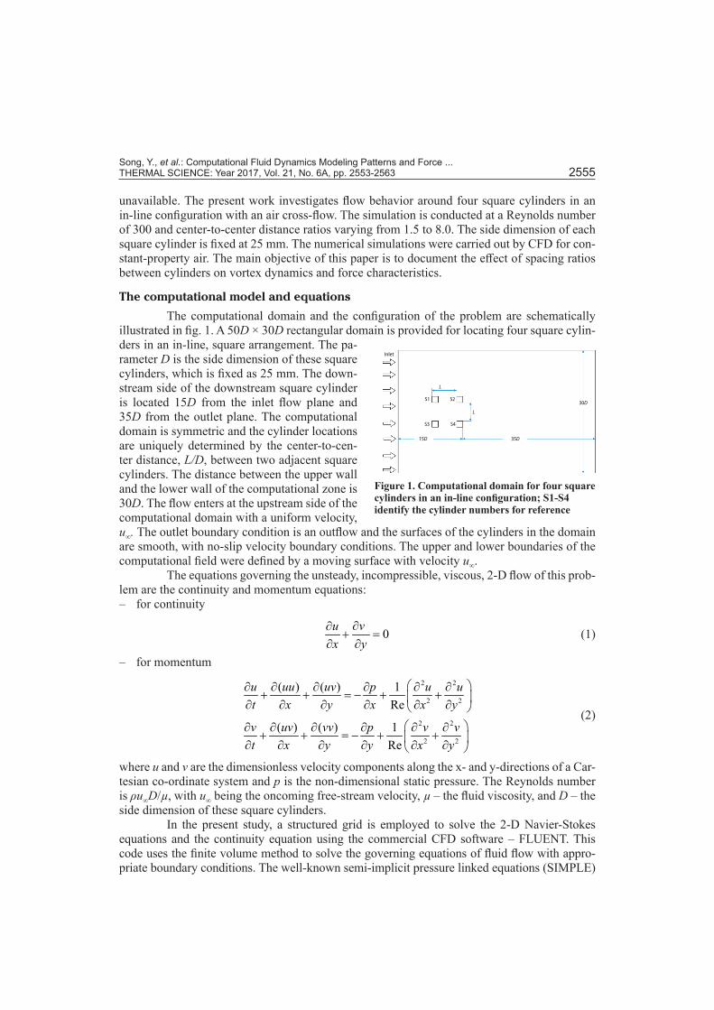
The computational domain and the configuration of the problem are schematically illustrated in fig. 1. A 50D × 30D rectangular domain is provided for locating four square cylin-ders in an in-line, square arrangement. The pa-rameter D is the side dimension of these square cylinders, which is fixed as 25 mm. The down-stream side of the downstream square cylinder is located 15D from the inlet flow plane and 35D from the outlet plane. The computational domain is symmetric and the cylinder locations are uniquely determined by the center-to-cen-ter distance, L/D, between two adjacent square cylinders. The distance between the upper wall and the lower wall of the computational zone is 30D. The flow enters at the upstream side of the computational domain with a uniform velocity, u∞. The outlet boundary condition is an outflow and the surfaces of the cylinders in the domain are smooth, with no-slip velocity boundary conditions. The upper and lower boundaries of the computational field were defined by a moving surface with velocity u∞.
The equations governing the unsteady, incompressible, viscous, 2-D flow of this prob-lem are the continuity and momentum equations: – for continuity
0vux y
∂∂+ =
∂ ∂ (1)
– for momentum
2 2
2 2
2 2
2 2
( ) ( ) 1Re
( ) ( ) 1Re
u uu uv p u ut x y x x y
v uv vv p v vt x y y x y
∂ ∂ ∂ ∂ ∂ ∂+ + = − + + ∂ ∂ ∂ ∂ ∂ ∂
∂ ∂ ∂ ∂ ∂ ∂+ + = − + + ∂ ∂ ∂ ∂ ∂ ∂
(2)
where u and v are the dimensionless velocity components along the x- and y-directions of a Car-tesian co-ordinate system and p is the non-dimensional static pressure. The Reynolds number is ρu∞D/µ, with u∞ being the oncoming free-stream velocity, µ – the fluid viscosity, and D – the side dimension of these square cylinders.
In the present study, a structured grid is employed to solve the 2-D Navier-Stokes equations and the continuity equation using the commercial CFD software – FLUENT. This code uses the finite volume method to solve the governing equations of fluid flow with appro-priate boundary conditions. The well-known semi-implicit pressure linked equations (SIMPLE)
Figure 1. Computational domain for four square cylinders in an in-line configuration; S1-S4 identify the cylinder numbers for reference
Inlet
S1
S3 S4
S2
35D15D
L
L
30D

Song, Y., et al.: Computational Fluid Dynamics Modeling Patterns and Force ... 2556 THERMAL SCIENCE: Year 2017, Vol. 21, No. 6A, pp. 2553-2563
scheme is utilized in the advection calculations, and the second-order discrete format is used for the pressure simulation. A second-order accurate upwind difference scheme is used because of its higher stability and accuracy than the first-order upwind scheme offers.
The mean drag coefficients, maximum amplitude of lift coefficients, and frequency of vor-tex shedding are discussed in this paper. Some definitions of these parameters are computed from:
22 DD
FCu Dρ ∞
= (3)
22 LL
FCu Dρ ∞
= (4)
St fDu∞
= (5)
where CD and CL are the drag and lift coefficients, respectively, St – the Strouhal number, FD – the force in the stream wise direction, and FL – the force in the transverse direction (lift). The velocity of the flow is u∞ and f is the vortex shedding frequency. The characteristic length scale is D, the side dimension of the square cylinder. It should be emphasized that the fluid is assumed to be incompressible and the dynamic viscosity is 1.5E–5 kg/ms in the current research.
The model validation
The grid independence test and the validation of numerical models have signifi-cant meaning for numerical simulations. The whole domain was discretized by the structured mesh illustrated in fig. 2. To ensure proper boundary-layer growth, flow separation and vortex growth, layers were constructed with y+ ≈ 1 in the region near the cylinder walls for all the
cases tested. The mesh size, Δy, around the cylinder could be obtained by the following relationship:
0.9'0.172 Reyy
L+ ∆= (6)
where the L’ is the feature length of the cyl-inder.
In view of the accuracy and cost of computation, four mesh sizes given the to-tal number of meshes of (116400, 124100, 147300, and 158700) were constructed for the grid independence test run at Re = 300. Table 1 shows the mean drag coefficients and maximum lift coefficients of these four mesh number cases. The percentage change in the values of time average coefficients and maximum lift coefficients for the coars-est grid (116400) with respect to the finest grid (158700) are found to be 1.85% and 3.57%, respectively. While the same for the
Figure 2. The structured mesh near the four square cylinders surfaces
Table 1. The drag coefficients and maximum lift coefficients under different mesh sizes
Mesh CD CLmax ΔCD ΔCLmax 116400 2.12 2.16 1.85% 3.57%124100 2.10 2.19 2.78% 2.23%147300 2.13 2.22 1.39% 0.89%158700 2.16 2.24 baseline baseline

Song, Y., et al.: Computational Fluid Dynamics Modeling Patterns and Force ... THERMAL SCIENCE: Year 2017, Vol. 21, No. 6A, pp. 2553-2563 2557
grids of 124100 are 2.78% and 2.23%, and the values for mesh 147300 are 1.39% and 0.89%. Accordingly, the 147300 mesh size is preferred, keeping in view the accuracy of the results and computational convenience in the simulations.
In order to validate the computational model, a case with uniform cross-flow along the x-direction over a single square cylinder with a diameter, D, for Reynolds number 250 was computed. Table 2 shows the com-parison with other works of computed mean drag coefficients and Strouhal numbers, at Re = 250 [22-24]. The calculated values of the CD and St match well the values in the literature. The validation results show that the model and methods used for the results to follow are well verified for the single cylinder and it is reasonable to assume that they could be em-ployed for simulating flow past four square cylinders in an in-line, square arrangement.
Results and discussion
The flow around four square cylinders in an in-line arrangement is expected to lead to different flow fields than those around a single or two cylinders. After validation of mesh in-dependence and numerical methods, a numerical simulation made by varying the spacing ratio for flow over four square cylinders at a Reynolds number of 300 was systematically carried out. In this section, the relationship between center-to-center distances, vortex shedding force parameters and other flow characteristics, are documented.
Flow patterns analysis
Figure 3 depicts the computed instantaneous vorticity patterns at a Reynolds number of 300 and spacing ratios, L/D, varying from 1.5 to 8.0. When L/D =1.5, the flow pattern behind the four square cylinders is similar to that of an isolated cylinder because the four cylinders are sufficiently close to each other. The vortices are immediately downstream of the cylinders, this can be attributed to the fact that the flow interferences between cylinders are quite strong with this small spacing ratio and, consequently, oscillating regions exist. In this case, the down-stream cylinders are totally engulfed by the shear layers of the upstream cylinders. The shed vortex wake behind the downstream cylinders (S2 and S4) is narrower than the vortex patterns of cases with the other spacing ratios. This is due to the inner shear layers of the upstream cyl-inders (S1 and S3) being biased toward one of the downstream cylinders. With this spacing, we can see a bi-stable state of wide and narrow wakes attached behind the downstream cylinders, which was also observed by Lam and Lo [25] with L/D =1.7. The flow pattern is almost steady during the whole process, called a stable shielding flow pattern (I) [18, 26]. The effect of jet flow between cylinders is obvious, and a larger flow acceleration results in strong jet spreading laterally behind the downstream cylinders.
Figures 3(b)-3(d) show that the inner shear layers of the upstream cylinders reattach immediately onto the downstream cylinder. However, there is no reattachment of the outer shear layers from the upstream cylinders on the downstream cylinders, and the outside shear layers are alternately wiggling near the downstream cylinders. Also, the vortex patterns merge behind the downstream cylinders at a small distance, and for those spacing ratios it is hard to show significant wiggling for both inner and outer shear layers. No vortex shedding occurs after the upstream cylinders, and the shear layers of the upper cylinders grow into mature vortices
Table 2. Comparisons of the Strouhal numbers and drag coefficients
Re Work name CD St
Re = 250
Saha et al. [22] 1.77 0.142Davis and Moore [23] 1.77 0.165
Franke et al. [24] 1.67 0.141Present work 1.72 0.149

Song, Y., et al.: Computational Fluid Dynamics Modeling Patterns and Force ... 2558 THERMAL SCIENCE: Year 2017, Vol. 21, No. 6A, pp. 2553-2563
after they have reattached to the downstream cylinders. This type of vortex pattern is referred to as a wiggling shielding flow pattern (II) [18, 26].
In figs. 3(e)-3(h), distinct vortex shedding from the upstream cylinders occur and a synchronized shedding pattern is observed. This type of vortex shedding is defined as the vor-tex shedding flow pattern (III) [18, 26]. These pictures clearly show that between the upstream cylinders (S1 to S2) there is a large scale re-circulation region and the vortex shedding pattern becomes mature because of free shear layers observed on the upstream cylinders which then impinge onto the downstream cylinders. The flow patterns remain distinct and move forward without any lateral spreading or distortion and the wake interactions are weak compared with those with smaller spacing ratios, and the vortices keep the same width and size. This is because of the relatively large distance between the upstream and downstream cylinders, which results in a weaker interaction between the upstream and downstream cylinders. With a larger spacing, the vortex pattern downstream of the four cylinders becomes steadier. A comparison of these four flow patterns shows that the overall flow patterns for L/D =6.0 and 7.0 are similar to those for the flow past two cylinders in a tandem arrangement.
Force characteristics and Strouhal numbers
Figure 4 illustrates the variations of time averaged drag coefficients, CD, with differ-ent spacing ratios, L/D, (1.5 to 8.0) with Re =300. To compute the time averaged value, the
Figure 3. Instantaneous flow patterns of four-cylinder array with different spacing ratios
(a) 1.5D (b) 2.5D
(c) 3.0D (d) 3.5D
(e) 4.0D (f) 5.0D
(g) 6.0D (h) 7.0D

Song, Y., et al.: Computational Fluid Dynamics Modeling Patterns and Force ... THERMAL SCIENCE: Year 2017, Vol. 21, No. 6A, pp. 2553-2563 2559
instantaneous values are averaged over ap-proximately 15 shedding cycles after the pe-riodic behavior condition (where the starting point for processing is unimportant) is met. This figure shows that the values of mean drag coefficients of upstream cylinders (S1 and S3) are close to each other, as are the values for the downstream cylinders (S2 and S4). The mean drag coefficients of upstream cylinders (S1 and S3) are much larger than those of the downstream cylinders (S2 and S4), which is a result of the downstream cyl-inders being mostly located in the wakes of the upstream cylinders; thus, the drag mainly acts on the upstream cylinders. Furthermore, all of the values are smaller than that for a single cylinder case. The mean drag forces, CD, of cylinders (S1 and S3) seem to keep constant with increasing spacing ratios when L/D > 4.0. Moreover, the variation of CD with L/D has a slight increase with the change of L/D from 1.5 to 4.0. The values of the mean drag coefficients for the downstream cylinders increase sharply with increasing spacing ratios when L/D < 3.5, this is because the outside free shear layers from the upper cylinders reattach to the downstream cylinders and parts of the drag are assigned to the downstream cylinders. However, at a higher spacing ratio, such as L/D > 3.5, the mean drag coefficients of the downstream cylinders de-crease gradually with increasing L/D. Lam et al. [17] and Lam and Fang [27] report that, with L/D < 2.0, CD4 is negative, while the present results show that CD4 values are small but positive.
Figures 5(a)-5(i) represent the time histories of drag coefficients for different spacing ratios. It is observed that the time signals for L/D = 1.5 show steady behavior compared with signals from cases of other spacing ratios. Upstream cylinders (S1 and S3) have similar fluctu-ating trends, especially for L/D > 4.0, where the drag coefficient curves of (S1 and S3) almost coincide with each other. It is found that the spacing ratio, L/D, has a significant influence on amplitudes of signals for downstream cylinders (S2 and S4). It can also be seen that the peri-odicity of values of drag coefficients for cylinders (S2 and S4) become somewhat lost and the signals become more disordered when 3.0 < L/D < 6.0.
Time averaged lift coefficients for four cylinders with different spacing ratios can be seen in fig. 6. The mean lift coefficients of upstream cylinders (S1 and S3) are generally equal in magnitude and opposite in direction and the value of lift force asymptotically approaches zero with increasing spacing ratio, L/D, on the upstream cylinders. This shows weakening of flow interference between the two rows of cylinders. The mean lift coefficient is not exactly symmetric about the x-axis because of bi-stable flow pattern that has been observed for this four-square-cylinders array. When L/D = 1.5-3.0, the mean lift of cylinder S1 gradually de-creases. However, when L/D > 3.0, the value slightly increases but still is negative, which results from a transformation of the flow pattern. For L/D > 3.0, the upstream (S1 and S3) and downstream (S2 and S4) cylinder pairs each have lift coefficients of opposite sign. The mean lift coefficients of downstream the cylinders (S2 and S4) are equal in magnitude and opposite in direction, except when L/D = 2.5 and 3.0. At the flow transition region (L/D = 3.0-4.0), a different trend of cylinder S2 can be seen, which indicates the mean lift forces of downstream cylinders are closely related to the transformation of flow patterns, figs. 3(b) and 3(c).
Figure 4. Time averaged drag coefficients of four cylinders at different spacing ratios
1.5D 2.5D 3D 3.5D 4D 5D 6D 7D 8D
0.0
0.5
1.0
1.5
2.0
Mea
n dr
ag c
oeffi
cien
tsL/D
S1 S2 S3 S4

Song, Y., et al.: Computational Fluid Dynamics Modeling Patterns and Force ... 2560 THERMAL SCIENCE: Year 2017, Vol. 21, No. 6A, pp. 2553-2563
Figure 7 shows the amplitude val-ues of lift coefficient oscillations for the four cylinders arrangements with different spacing ratios. It can be seen that the am-plitude values of lift of the downstream cylinders (S2 and S4) are about 1.5 times those of the upstream cylinders (S1 and S3) when L/D > 2.5, which illustrates a stabilizing effect of shielding flow on the upper cylinders and vortex shedding after the downstream cylinders. It is interesting to note that the trends and magnitudes of amplitude values of lift force of upstream cylinders (S1 and S3) are basically the same, as are those of downstream cylin-ders (S2 and S4). The changes of the mean
Figure 5. Time history analysis of drag coefficients with different spacing ratios
228 230 232 234 236 238-1
0
1
2
3
4
5CD
Time
S1 S2 S3 S4
84 85 86 87 88 89-1
0
1
2
3
4
5
Time50 52 54 56 58 60
-10
1
2
3
4
5
Time
160 162 164 166 168 170-1
0
1
2
3
4
5
Time36 38 40 42 44
-1
0
1
2
3
4
5
Time80 82 84 86 88 90
-1
0
1
2
3
4
5
Time
30 32 34 36 38 40-1
0
1
2
3
4
5
Time20 22 24 26 28 30
-1
0
1
2
3
4
5
Time30 32 34 36 38 40
-1
0
1
2
3
4
5
Time
(a)
1.5D
(b)
2.5D
(c)
3.0D
(d)
3.5D
(e)
4.0D
(f)
5.0D
(g)
6.0D
(h)
7.0D
(i)
8.0D
CD CD
CDCDCD
CD CD CD
Figure 6. Time averaged lift coefficients of four cylinders with different spacing ratios
1.5D 2.5D 3D
Mea
n lif
t coe
ffici
ents
4D 5D 6D 7D 8D-0.4
-0.2
0.0
0.2
0.4
L/D
S1 S2 S3 S4

Song, Y., et al.: Computational Fluid Dynamics Modeling Patterns and Force ... THERMAL SCIENCE: Year 2017, Vol. 21, No. 6A, pp. 2553-2563 2561
lift coefficients on the downstream cylinders are significantly larger than changes on the upstream cylinders for L/D > 4.0.
The variation of Strouhal number with center-to-center distance ratio is depicted in fig. 8. The values of Strouhal number are obtained through frequency analysis of the lift force using fast fourier transform func-tion. It is worth mentioning that the frequen-cies of cylinder S1 are the same as those of cylinder S2, and, similarly, for cylinders (S3 and S4), so the Strouhal number values of cylinders (S1 and S3) are discussed in this paper. From fig. 8, we can see that the trends of cylinders (S1 and S3) are almost the same but there exists a slight difference of magni-tudes of Strouhal number. The values of Strouhal number gradually increase and approach the vortex frequency of flow around a single cylinder with increasing of L/D, while the growth rate of Strouhal numbers reduces beyond L/D = 4.0.
Conclusions
This paper presents a 2-D numerical scheme for documentation of the effects of spac-ing ratio on laminar flow fields and forces for field around four square cylinders in an in-line square configuration at a Reynolds number of 300. Valuable data, such as the wake structure, drag and lift force characteristics, and Strouhal numbers are obtained.
In general, the wake patterns vary from a bi-stable shielded flow pattern to a vortex shedding flow pattern with increases of spacing ratio. The critical spacing ratio for Re = 300 is around a value of L/D = 3.5. For a smaller spacing ratio, the interferences from the side cylin-ders become more pronounced and forces on the cylinders opposed in direction increase. The interference between two cylinders in tandem is much stronger than seen between side-by-side cylinders, with a larger L/D.
The patterns of flow around four cylinders have an essential influence on the force dis-tributions. Smaller drag forces are exerted on downstream cylinders because they are engulfed
Figure 7. The amplitudes of lift coefficients for four cylinders with different spacing ratios; (a) the maximum amplitude, (b) the minimum amplitude
1.5D 2.5D 3D 4D 5D 6D 7D 8D-0.5
0.0
0.5
1.0
1.5
2.0
2.5
3.0
3.5
L/D
S1 S2 S3 S4
1.5D 2.5D 3D 4D 5D 6D 7D 8D-4.0
-3.5
-3.0
-2.5
-2.0
-1.5
-1.0
-0.5
0.0
0.5
L/D
S1 S2 S3 S4
Max
am
plitu
de o
f CL
Min
am
plitu
de o
f CL
Figure 8. Strouhal numbers of S1 and S3 with different spacings
2.5D 3D 3.5D 4D 5D 6D 7D 8D0.85
0.90
0.95
1.00
1.05
1.10
St
L/D
S1 S3

Song, Y., et al.: Computational Fluid Dynamics Modeling Patterns and Force ... 2562 THERMAL SCIENCE: Year 2017, Vol. 21, No. 6A, pp. 2553-2563
by the outer shear layers of upstream cylinders. The mean lift coefficients of the two upstream cylinders are generally equal in magnitude and opposite in direction to those of the two down-stream cylinders.
Acknowledgment
The authors wish thanks, the National Natural Science Foundation of China (51676163) and the Fundamental Research Funds of Shaanxi Province (2015KJXX-12). This work was carried out in part using computing resources at the University to Minnesota Super-computing Institute.
NomenclatureCD – mean drag coefficient of the cylinders, [–]CD4 – mean drag coefficient of the
four cylinders, [–]CL – mean lift coefficient of the cylinders, [–]D – square cylinders side dimension, [m]FD – force in the stream-wise direction, [N]]FL – force in the transverse direction, [N]f – vortex shedding frequency, [–]L – distance between two cylinders, [m]L’ – feature length of the cylinders, [m]L/D – spacing ratio of two cylinders, [–]p – pressure, [Pa]Re – Reynolds number, [–]St – Strouhal numbers of downstream cylinder, [–]
S1 – number of cylinder 1S2 – number of cylinder 2S3 – number of cylinder 3S4 – number of cylinder 4t – temperature [K]u∞ – inlet velocity of flow, [ms–1]u – dimensionless x-velocity, [–]v – dimensionless y-velocity, [–]x, y – axial and normal co-ordinates, [m] Δy – mesh size close the cylinders wall, [–]
Greek symbols
μ – kinematic viscosity of fluid, [m2s–1] ρ – flow density, [kgm–3]
References[1] Sumner, D., Two Circular Cylinders in Cross-Flow: A review, Journal of Fluids and Structures, 26 (2010),
6, pp. 849-899[2] Han, Z. L., et al., Flow Past Two Tandem Circular Cylinders Using Spectral Element Method, Proceed-
ings, 7th International Colloquium on Bluff Body Aerodynamics and Applications (BBAA7), Shanghai, China, 2012, pp. 546-554
[3] Mittal, S., Kumar, V. A., Unsteady Incompressible Flows Past Two Cylinders in Tandem and Staggered Arrangements, International Journal of Numerical Methods in Fluids, 25 (1997), 11, pp. 1315-1344
[4] Huang, G., et al., Simulation of Flow Past Two Tandem Cylinders Using Deterministic Vortex Method, Thermal Science, 16 (2012), 5, pp. 1460-1464
[5] Agrawal, A., et al., Investigation of Flow around a Pair of Side-by-Side Square Cylinders Using the Lat-tice Boltzmann Method, Computer and Fluids, 35 (2006), 10, pp. 1093-1107
[6] Sumner, D., et al., Flow-Pattern Identification for Two Staggered Circular Cylinders in Cross-Flow, Jour-nal of Fluid Mechanics, 411 (2000), May, pp. 263-303
[7] Nikolay, P. M., Jakgrit, S., Numerical Simulation of Heat Transfer and Fluid Flow over Two Rotating Circular Cylinders at Low Reynolds Number, Heat Transfer Asian Research, 39 (2010), 4, pp. 246-261
[8] Mohammad, S. V., Ariyan, Z. G., Numerical Investigation of Fluid Flow and Heat Transfer around a Solid Circular Cylinder Utilizing Nanofluid, International Communications in Heat and Mass Transfer, 38 (2011), 9, pp. 1296-1304
[9] Afshin, M., et al., Convective Cooling of Tandem Heated Triangular Cylinders Placed in a Channel, Ther-mal Science, 14 (2010), 1, pp. 183-197
[10] Chang, B. H., Mills, A. F., Effect of Aspect Ratio on Forced Convection Heat Transfer from Cylinders, International Journal of Heat and Mass Transfer, 47 (2004), 6, pp. 1289-1296
[11] Sayers, A. T., Flow Interference between Four Equispaced Cylinders when Subjected to a Cross Flow, Journal of Wind Engineering and Industrial Aerodynamics, 31 (1988), 1, pp. 9-28
[12] Ladjedel, O., et al., Experimental Investigation of Turbulent Flow Past Four Grooved and Smooth Cylin-ders in an In-Line Square Arrangement, EPJ Web of Conference, 92 (2015), May, pp. 02046-1-02046-4

Song, Y., et al.: Computational Fluid Dynamics Modeling Patterns and Force ... THERMAL SCIENCE: Year 2017, Vol. 21, No. 6A, pp. 2553-2563 2563
[13] Waqas, S. A., et al., Effect of Reynolds Numbers on Flow Past Four Square Cylinders in an In-Line Square Configuration for Different Gap Spacing, Journal of Mechanical Science and Technology, 28 (2014), 2, pp. 539-552
[14] Lam, K., Zou, L., Experimental and Numerical Study for the Cross-Flow around Four Cylinders in an In-Line Square Configuration, Journal of Mechanical Science and Technology, 21 (2007), 9, pp. 1338-1343
[15] Zou, L., et al., Flow Patterns and Force Characteristics of Laminar Flow Past Four Cylinders in Diamond Arrangement, Journal of Hydrodynamics, 23 (2011), 1, pp. 55-64
[16] Lam, K., et al., Flow Pattern and Velocity Field Distribution of Cross-Flow around Four Cylinders in a Square Configuration at Low Reynolds Number, Journal of Fluids and Structures, 17 (2003), 5, pp. 579-665
[17] Lam, K., et al., Force Coefficient and Strouhal Numbers of Four Cylinders in Cross Flow, Journal of Fluids and Structures, 18 (2003), 3, pp. 305-324
[18] Lam, K., et al., Numerical Simulation of Cross-Flow around Four Cylinders in an In-Line Square Config-uration, Journal of Fluids and Structures, 24 (2008), 1, pp. 34-57
[19] Huang, L. Z., Nie, D. M., Vortex Shedding Patterns in Flow Past Inline Oscillating Elliptical Cylinders, Thermal Science, 16 (2012), 5, pp. 1395-1399
[20] Alam, M. M., et al., The Wake of Two Side-by-Side Square Cylinders, Journal of Fluid Mechanics, 669 (2011), Feb., pp. 432-471
[21] Yen, S. C., et al., Interactions of Tandem Square Cylinders at Low Reynolds Numbers, Experimental Thermal and Fluid Science, 32 (2008), 4, pp. 927-938
[22] Saha, A. K., et al., Transition and Chaos in a 2-D Flow Past a Square Cylinder, ASME Journal of Engi-neering Mechanics, 136 (2000), 5, pp. 523-532
[23] Davis, R., Moore, E. F., A Numerical Study of Vortex Shedding from Rectangles, Journal of Fluid Me-chanics, 116 (1982), 5, pp. 475-506
[24] Franke, R., et al., Numerical Calculation of Laminar Vortex Shedding for Flow Past Cylinders, Journal of Wind Engineering and Industrial Aerodynamics, 35 (1990), Jan., pp. 237-257
[25] Lam, K., Lo, S. C., A Visualization Study of Cross-Flow around Four Cylinders in a Square Configura-tion, Journal of Fluids and Structures, 6 (1992), 1, pp. 109-131
[26] Kang, X. Y., Su, Y. P., Lattice Boltzmann Simulation of Flow around Two, Three and Four Circular Cylin-ders in Close Proximity, Science China, Physics, Mechanics & Astronomy, 55 (2012), 10, pp. 1873-1885
[27] Lam, K., Fang, X., The Effect of Interference of Four Equi-Spaced Cylinders in Cross Flow on Pressure and Force Coefficients, Journal of Fluids and Structures, 9 (1995), 2, pp. 195-214
Paper submitted: February 11, 2017Paper revised: February 13, 2017Paper accepted: February 25, 2017
© 2017 Society of Thermal Engineers of SerbiaPublished by the Vinča Institute of Nuclear Sciences, Belgrade, Serbia.
This is an open access article distributed under the CC BY-NC-ND 4.0 terms and conditions