Computational Fluid Dynamics
12
Engineering & Expertise Hydraulic modeling COMPUTATIONAL FLUID DYNAMICS
-
Upload
kudzie-craig-kelvin-mutasa -
Category
Documents
-
view
31 -
download
6
description
cfd
Transcript of Computational Fluid Dynamics
Engineering & ExpertiseHydraulic modelingComputational fluid dynamiCs
Theo
retic
al a
naly
sis
Products
Reference installations
Physical tests
E n g i n e e r i n g & E x p e r t i s e
Investment
UnplannedOperational
2
EnginEEring & ExpErtisE
total solution engineeringincreases operational efficiency
introduction
Understanding fluid flow inside hydraulic structures is a critical factor in the design of pump stations. But intuition and expe-rience are not always enough to develop optimized solutions or to communicate with customers about the advantages of the proposed design. Computational Fluid Dynamics, or CFD, is an excellent modeling tool that can be used in the design process to simulate various design alternatives, iden-tify flow problems, develop solutions and evaluate operating strategies. As such, the CFD is a cost-effective alternative to physical modeling.
in this brochure, we will show how we use CFD to solve engineering problems related to pump station design for specific customer projects. But we also use CFD in developing generic designs for different types of pump stations or process applications, and last but not least, we use CFD in the design of pumps and mixers.
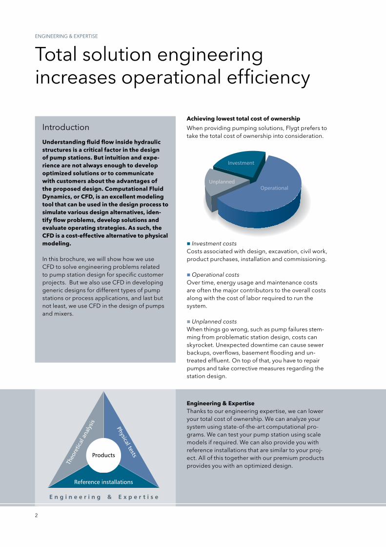
Achieving lowest total cost of ownership
Investment costsCosts associated with design, excavation, civil work, product purchases, installation and commissioning.
Operational costsOver time, energy usage and maintenance costs are often the major contributors to the overall costs along with the cost of labor required to run the system.
Unplanned costsWhen things go wrong, such as pump failures stem-ming from problematic station design, costs can sky rocket. Unexpected downtime can cause sewer backups, overflows, basement flooding and un-treated effluent. On top of that, you have to repair pumps and take corrective measures regarding the station design.
When providing pumping solutions, Flygt prefers to take the total cost of ownership into consideration.
Engineering & Expertisethanks to our engineering expertise, we can lower your total cost of ownership. We can analyze your system using state-of-the-art computational pro-grams. We can test your pump station using scale models if required. We can also provide you with reference installations that are similar to your proj-ect. All of this together with our premium products provides you with an optimized design.
3
intrODUCtiOn
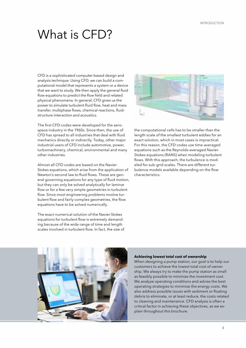
Achieving lowest total cost of ownershipWhen designing a pump station, our goal is to help our customers to achieve the lowest total cost of owner-ship. We always try to make the pump station as small as feasibly possible to minimize the investment cost. We analyze operating conditions and advise the best operating strategies to minimize the energy costs. We also address possible issues with sediment or floating debris to eliminate, or at least reduce, the costs related to cleaning and maintenance. CFD analysis is often a critical factor in achieving these objectives, as we ex-plain throughout this brochure.
What is CFD?
CFD is a sophisticated computer-based design and analysis technique. Using CFD, we can build a com-putational model that represents a system or a device that we want to study. We then apply the general fluid flow equations to predict the flow field and related physical phenomena. in general, CFD gives us the power to simulate turbulent fluid flow, heat and mass transfer, multiphase flows, chemical reactions, fluid-structure interaction and acoustics.
the first CFD codes were developed for the aero-space industry in the 1960s. since then, the use of CFD has spread to all industries that deal with fluid mechanics directly or indirectly. today, other major industrial users of CFD include automotive, power, turbomachinery, chemical, environmental and many other industries.
Almost all CFD codes are based on the navier-stokes equations, which arise from the application of newton’s second law to fluid flows. these are gen-eral governing equations for any type of fluid motion, but they can only be solved analytically for laminar flow or for a few very simple geometries in turbulent flow. since most engineering problems involve tur-bulent flow and fairly complex geometries, the flow equations have to be solved numerically.
the exact numerical solution of the navier-stokes equations for turbulent flow is extremely demand-ing because of the wide range of time and length scales involved in turbulent flow. in fact, the size of
the computational cells has to be smaller than the length scale of the smallest turbulent eddies for an exact solution, which in most cases is impractical. For this reason, the CFD codes use time-averaged equations such as the reynolds-averaged navier-stokes equations (rAns) when modeling turbulent flows. With this approach, the turbulence is mod-eled for sub-grid scales. there are different tur-bulence models available depending on the flow characteristics.
4
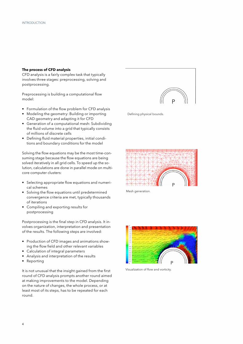
Mesh generation.
Visualization of flow and vorticity.
p
Defining physical bounds.
p
p
intrODUCtiOn
The process of CFD analysisCFD analysis is a fairly complex task that typically involves three stages: preprocessing, solving and postprocessing.
preprocessing is building a computational flow model:
• FormulationoftheflowproblemforCFDanalysis• Modelingthegeometry:Buildingorimporting
CAD geometry and adapting it for CFD• Generationofacomputationalmesh:Subdividing
the fluid volume into a grid that typically consists of millions of discrete cells
• Definingfluidmaterialproperties,initialcondi-tions and boundary conditions for the model
solving the flow equations may be the most time-con-suming stage because the flow equations are being solved iteratively in all grid cells. to speed up the so-lution, calculations are done in parallel mode on multi-core computer clusters:
• Selectingappropriateflowequationsandnumeri-cal schemes
• Solvingtheflowequationsuntilpredeterminedconvergence criteria are met, typically thousands of iterations
• Compilingandexportingresultsforpostprocessing
postprocessing is the final step in CFD analysis. it in-volves organization, interpretation and presentation of the results. the following steps are involved:
• ProductionofCFDimagesandanimationsshow-ing the flow field and other relevant variables
• Calculationofintegralparameters• Analysisandinterpretationoftheresults• Reporting
it is not unusual that the insight gained from the first round of CFD analysis prompts another round aimed at making improvements to the model. Depending on the nature of changes, the whole process, or at least most of its steps, has to be repeated for each round.
5
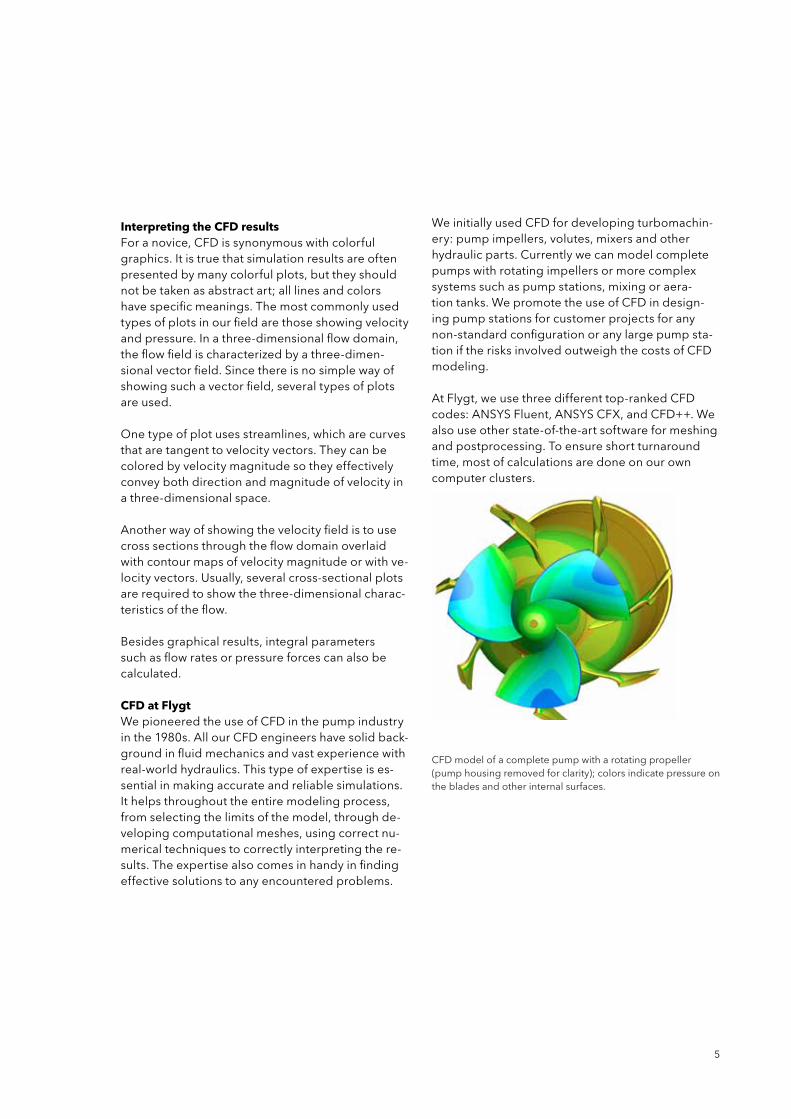
CFD model of a complete pump with a rotating propeller (pump housing removed for clarity); colors indicate pressure on the blades and other internal surfaces.
Interpreting the CFD resultsFor a novice, CFD is synonymous with colorful graphics. it is true that simulation results are often presented by many colorful plots, but they should not be taken as abstract art; all lines and colors have specific meanings. the most commonly used types of plots in our field are those showing velocity and pressure. in a three-dimensional flow domain, the flow field is characterized by a three-dimen-sional vector field. since there is no simple way of showing such a vector field, several types of plots are used.
One type of plot uses streamlines, which are curves that are tangent to velocity vectors. they can be colored by velocity magnitude so they effectively convey both direction and magnitude of velocity in a three-dimensional space.
Another way of showing the velocity field is to use cross sections through the flow domain overlaid with contour maps of velocity magnitude or with ve-locity vectors. Usually, several cross-sectional plots are required to show the three-dimensional charac-teristics of the flow.
Besides graphical results, integral parameters such as flow rates or pressure forces can also be calculated.
CFD at FlygtWe pioneered the use of CFD in the pump industry in the 1980s. All our CFD engineers have solid back-ground in fluid mechanics and vast experience with real-world hydraulics. this type of expertise is es-sential in making accurate and reliable simulations. it helps throughout the entire modeling process, from selecting the limits of the model, through de-veloping computational meshes, using correct nu-merical techniques to correctly interpreting the re-sults. the expertise also comes in handy in finding effective solutions to any encountered problems.
We initially used CFD for developing turbomachin-ery: pump impellers, volutes, mixers and other hydraulic parts. Currently we can model complete pumps with rotating impellers or more complex systems such as pump stations, mixing or aera-tion tanks. We promote the use of CFD in design-ing pump stations for customer projects for any non-standard configuration or any large pump sta-tion if the risks involved outweigh the costs of CFD modeling.
At Flygt, we use three different top-ranked CFD codes: AnsYs Fluent, AnsYs CFx, and CFD++. We also use other state-of-the-art software for meshing and postprocessing. to ensure short turnaround time, most of calculations are done on our own computer clusters.
6
DEsign COnDitiOns
Adverse hydraulic phenomena
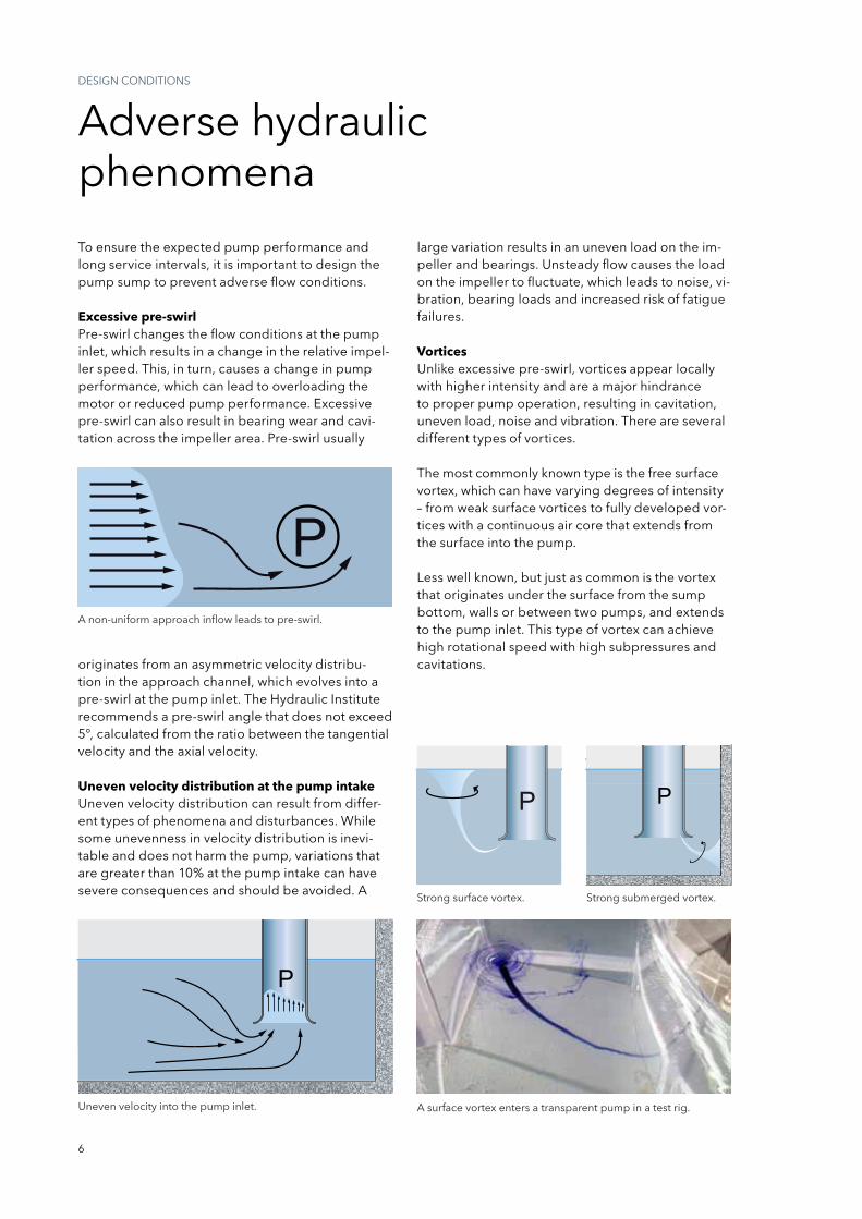
A non-uniform approach inflow leads to pre-swirl.
Uneven velocity into the pump inlet.
to ensure the expected pump performance and long service intervals, it is important to design the pump sump to prevent adverse flow conditions.
Excessive pre-swirlpre-swirl changes the flow conditions at the pump inlet, which results in a change in the relative impel-ler speed. this, in turn, causes a change in pump performance, which can lead to overloading the motor or reduced pump performance. Excessive pre-swirl can also result in bearing wear and cavi-tation across the impeller area. pre-swirl usually
originates from an asymmetric velocity distribu-tion in the approach channel, which evolves into a pre-swirl at the pump inlet. the Hydraulic institute recommends a pre-swirl angle that does not exceed 5°, calculated from the ratio between the tangential velocity and the axial velocity.
Uneven velocity distribution at the pump intakeUneven velocity distribution can result from differ-ent types of phenomena and disturbances. While some unevenness in velocity distribution is inevi-table and does not harm the pump, variations that are greater than 10% at the pump intake can have severe consequences and should be avoided. A
large variation results in an uneven load on the im-peller and bearings. Unsteady flow causes the load on the impeller to fluctuate, which leads to noise, vi-bration, bearing loads and increased risk of fatigue failures.
VorticesUnlike excessive pre-swirl, vortices appear locally with higher intensity and are a major hindrance to proper pump operation, resulting in cavitation, uneven load, noise and vibration. there are several different types of vortices.
the most commonly known type is the free surface vortex, which can have varying degrees of intensity – from weak surface vortices to fully developed vor-tices with a continuous air core that extends from the surface into the pump.
Less well known, but just as common is the vortex that originates under the surface from the sump bottom, walls or between two pumps, and extends to the pump inlet. this type of vortex can achieve high rotational speed with high subpressures and cavitations.
strong surface vortex. strong submerged vortex.
A surface vortex enters a transparent pump in a test rig.
7
CAsE stUDiEs
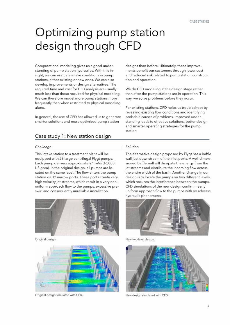
Original design simulated with CFD. new design simulated with CFD.
Optimizing pump station design through CFD
Computational modeling gives us a good under-standing of pump station hydraulics. With this in-sight, we can evaluate intake conditions in pump stations, either existing or new ones. We can also develop improvements or design alternatives. the required time and cost for CFD analysis are usually much less than those required for physical modeling. We can therefore model more pump stations more frequently than when restricted to physical modeling alone.
in general, the use of CFD has allowed us to generate smarter solutions and more optimized pump station
Original design. new two-level design.
designs than before. Ultimately, these improve-ments benefit our customers through lower cost and reduced risk related to pump station construc-tion and operation.
We do CFD modeling at the design stage rather than after the pump stations are in operation. this way, we solve problems before they occur.
For existing stations, CFD helps us troubleshoot by revealing existing flow conditions and identifying probable causes of problems. improved under-standing leads to effective solutions, better design and smarter operating strategies for the pump station.
Case study 1: new station design
this intake station to a treatment plant will be equipped with 23 large centrifugal Flygt pumps. Each pump delivers approximately 1 m³/s (16,000 Us gpm). in the original design, all pumps are lo-cated on the same level. the flow enters the pump station via 12 narrow ports. these ports create very high velocity jet streams, which result in a very non-uniform approach flow to the pumps, excessive pre-swirl and consequently unreliable installation.
the alternative design proposed by Flygt has a baffle wall just downstream of the inlet ports. A well dimen-sioned baffle wall will dissipate the energy from the jet streams and distribute the incoming flow across the entire width of the basin. Another change in our design is to locate the pumps on two different levels, which reduces the interference between the pumps. CFD simulations of the new design confirm nearly uniform approach flow to the pumps with no adverse hydraulic phenomena.
Challenge | Solution
8
CAsE stUDiEs
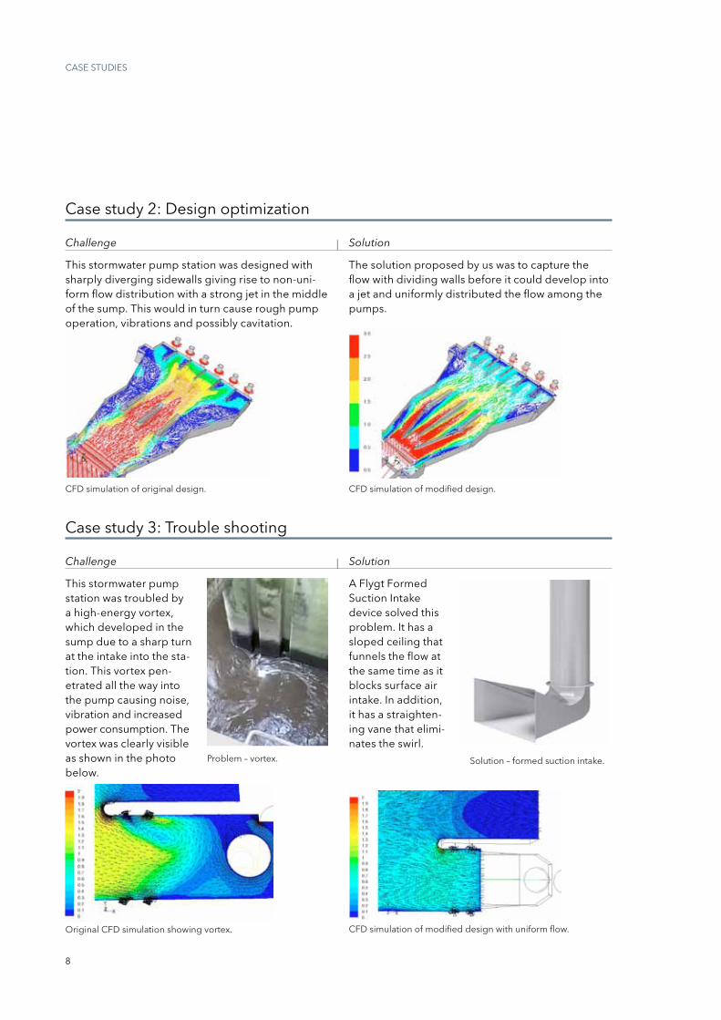
Case study 2: Design optimization
CFD simulation of original design. CFD simulation of modified design.
the solution proposed by us was to capture the flow with dividing walls before it could develop into a jet and uniformly distributed the flow among the pumps.
Challenge | Solution
this stormwater pump station was designed with sharply diverging sidewalls giving rise to non-uni-form flow distribution with a strong jet in the middle of the sump. this would in turn cause rough pump operation, vibrations and possibly cavitation.
problem – vortex.
Original CFD simulation showing vortex.
solution – formed suction intake.
CFD simulation of modified design with uniform flow.
Case study 3: trouble shooting
Challenge | Solution
this stormwater pump station was troubled by a high-energy vortex, which developed in the sump due to a sharp turn at the intake into the sta-tion. this vortex pen-etrated all the way into the pump causing noise, vibration and increased power consumption. the vortex was clearly visible as shown in the photo below.
A Flygt Formed suction intake device solved this problem. it has a sloped ceiling that funnels the flow at the same time as it blocks surface air intake. in addition, it has a straighten-ing vane that elimi-nates the swirl.
9
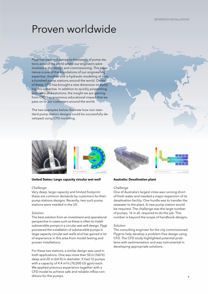
proven worldwide
Flygt has supplied pumps to thousands of pump sta-tions around the world where our engineers were involved in the design and commissioning. this expe-rience is one of the foundations of our engineering expertise. Another one is hydraulic modeling of over a hundred pump stations around the world. On top of these, CFD has brought a new dimension to build-ing this expertise. in addition to quickly pinpointing problems and solutions, the insight we are gaining from CFD has enormous educational impact that we pass on to our customers around the world.
the two examples below illustrate how non-stan-dard pump station designs could be successfully de-veloped using CFD modeling.
rEFErEnCE instALLAtiOns
Australia: Desalination plant
ChallengeOne of Australia’s largest cities was running short of fresh water and needed a major expansion of its desalination facility. One hurdle was to transfer the seawater to the plant. A new pump station would be required. the challenge was the large number of pumps, 16 in all, required to do the job. this number is beyond the scope of handbook designs.
Solutionthe consulting engineer for the city commissioned Flygt to help develop a problem-free design using CFD. the CFD study highlighted potential prob-lems with sedimentation and was instrumental in developing appropriate solutions.
United States: Large capacity circular wet well
ChallengeVery deep, large capacity and limited footprint: these are common demands by customers for their pump stations designs. recently, two such pump stations were needed in the Us.
Solutionthe best solution from an investment and operational perspective in cases such as these is often to install submersible pumps in a circular wet well design. Flygt pioneered the installation of submersible pumps in large capacity circular wet wells and has gained a lot of experience in this area from model testing and proven installations.
For these two stations, a similar design was used in both applications. One was more than 50 m (160 ft) deep and 20 m (64 ft) in diameter. it had 12 pumps with a capacity of 4.4 m³/s (70,000 Us gpm) each. We applied previous experience together with a CFD model to achieve safe and reliable inflow con-ditions for the pumps.
solution – formed suction intake.

10
Engineering & ExpertisesErViCEs AnD sUppOrt
theoretical analysis
Design tools
When you design pump stations, we can offer advanced engineering tools to generate sump designs. Our design recommendations give you essential information regarding dimensions and layout. in short, we assist you every step of the way to make sure you optimize performance and achieve energy-efficient operations.
To ensure reliable and highly efficient operation, we offer comprehensive support and service for pump station design, system analysis, installation, commissioning, operation and maintenance.
Computational fluid dynamics (CFD) can provide far more detailed information about the flow field in a fraction of the time required to get the same infor-mation through physical hydraulic scale model test-ing. Using CFD in combination with computer-aided design (CAD) tools, it is possible to obtain a more efficient method of numerical simulation for pump station design.
to obtain a reliable, energy-efficient pumping system, it is important to analyze all modes of op-eration. to analyze the transient effects at pump start and stop with respect to flow and head as well as the electrical parameters such as current and torque, it is also important to have an accurate mathematical description of the pump and motor, which is gained, in part, from extensive testing in our laboratories.
Theo
retic
al a
naly
sis
Products
Reference installations
Physical tests
E n g i n e e r i n g & E x p e r t i s e
11
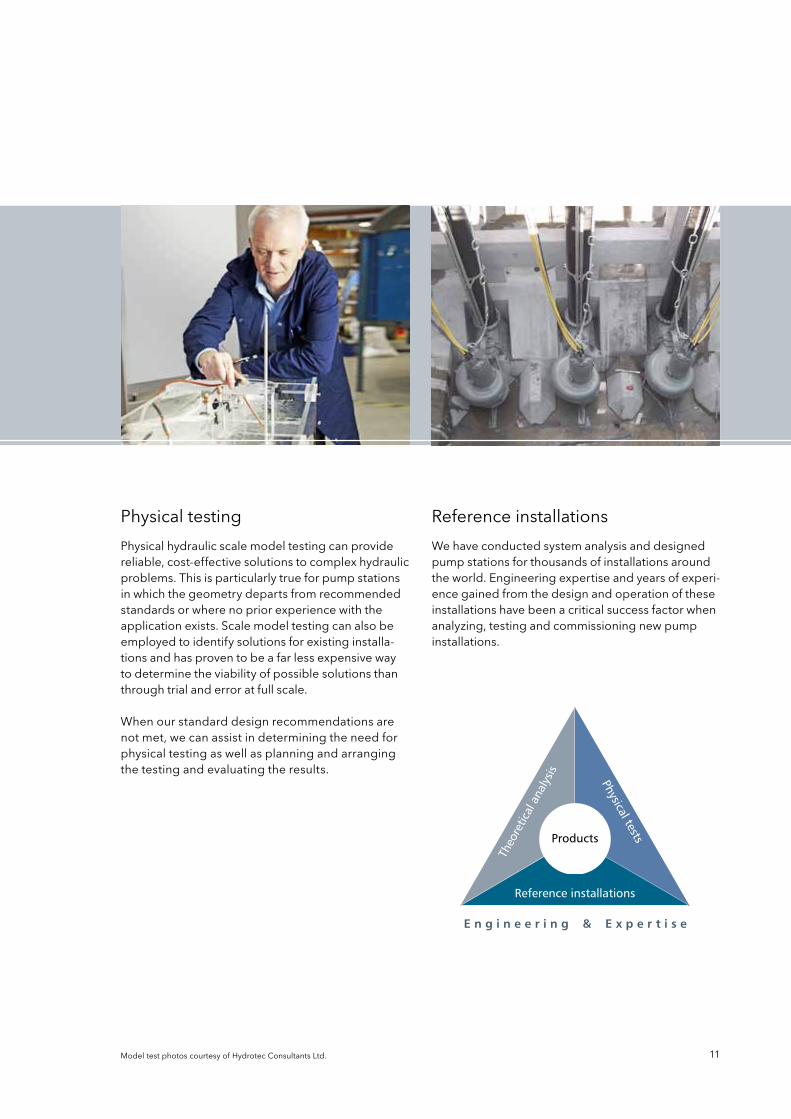
physical testing reference installations
physical hydraulic scale model testing can provide reliable, cost-effective solutions to complex hydraulic problems. this is particularly true for pump stations in which the geometry departs from recommended standards or where no prior experience with the application exists. scale model testing can also be employed to identify solutions for existing installa-tions and has proven to be a far less expensive way to determine the viability of possible solutions than through trial and error at full scale.
When our standard design recommendations are not met, we can assist in determining the need for physical testing as well as planning and arranging the testing and evaluating the results.
We have conducted system analysis and designed pump stations for thousands of installations around the world. Engineering expertise and years of experi-ence gained from the design and operation of these installations have been a critical success factor when analyzing, testing and commissioning new pump installations.
Model test photos courtesy of Hydrotec Consultants Ltd.
Flygt is a brand of xylem. For the latest version of this document and more information about Flygt products visitwww.flygt.com
1200
. H
ydra
ulic
Mo
del
ing
. 1
. Mas
ter
. 1
. 201
2041
9
1) the tissue in plants that brings water upward from the roots 2) A leading global water technology company We’re 12,000 people unified in a common purpose: creating innovative solutions to meet our world’s water needs. Developing new technologies that will improve the way water is used, conserved, and re-used in the future is central to our work. We move, treat, analyze, and return water to the environment, and we help people use water efficiently, in their homes, buildings, factories and farms. in more than 150 countries, we have strong, long-standing relationships with customers who know us for our powerful combination of leading product brands and applications expertise, backed by a legacy of innovation. For more information on how xylem can help you, go to xyleminc.com.