Computational Analysis of Internal and External EGR ... · PDF fileThe Miller cycle is an...
27
GT-Suite Users International Conference Frankfurt a.M., October 22 nd 2012 Computational Analysis of Internal and External EGR Strategies combined with Miller Cycle Concept for a Two Stage Turbocharged Medium Speed Marine Diesel Engine F. Millo, M. Gianoglio Bernardi (Politecnico di Torino - Italy) D. Delneri (Wärtsilä)
Transcript of Computational Analysis of Internal and External EGR ... · PDF fileThe Miller cycle is an...

GT-Suite Users International ConferenceFrankfurt a.M., October 22nd 2012
Computational Analysis of Internal and External EGR Strategies
combined with Miller Cycle Concept for a Two Stage Turbocharged
Medium Speed Marine Diesel Engine
F. Millo, M. Gianoglio Bernardi (Politecnico di Torino - Italy)
D. Delneri (Wärtsilä)

Presentation Overview
• Introduction
• Model set-up and validation
• Dual stage turbocharging and Miller cycle analysis
• External EGR analysis
• Conclusions

Presentation Overview
• Introduction
• Model set-up and validation
• Dual stage turbocharging and Miller cycle analysis
• External EGR analysis
• Conclusions
Introduction
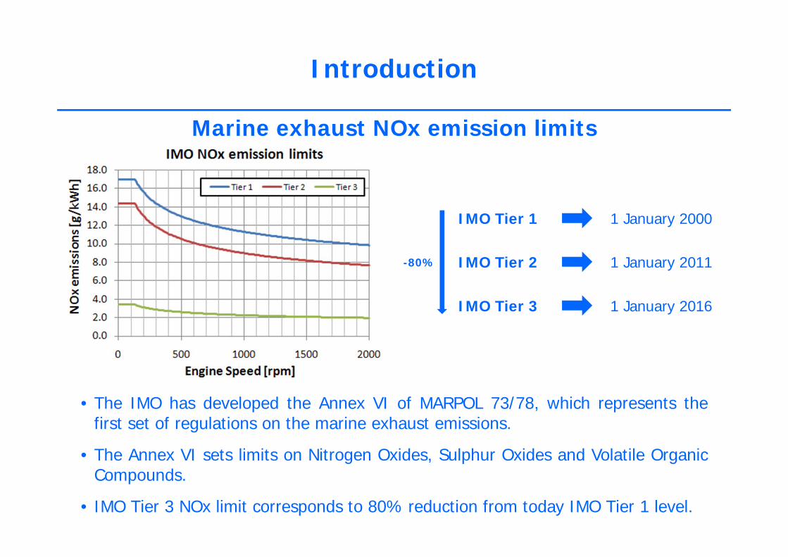
Marine exhaust NOx emission limits
• The IMO has developed the Annex VI of MARPOL 73/78, which represents thefirst set of regulations on the marine exhaust emissions.
• The Annex VI sets limits on Nitrogen Oxides, Sulphur Oxides and Volatile OrganicCompounds.
• IMO Tier 3 NOx limit corresponds to 80% reduction from today IMO Tier 1 level.
IMO Tier 1
IMO Tier 2
IMO Tier 3
1 January 2000
1 January 2011
1 January 2016
-80%

Introduction
Emission Control Areas (ECA’s)

Introduction
NOx emission reduction technologies potentials
Although different combustion and aftertreatment technologies could be combined
in order to reach the IMO Tier 3 NOx emissions target, the aim of this work is the
analysis of the potential of internal and external Exhaust Gas Recirculation
strategies combined with Miller cycle concept and dual stage turbocharging.

Introduction
Miller cycle concept and two stage turbochargingOne possible strategy to approach IMO Tier 3 limits and decrease NOx emissions is thecombustion process cooling that can be achieved using a Miller cycle.
The Miller cycle is an operating cycle for ICE which is essentially characterized by aneffective compression stroke shorter than the expansion stroke.
Diesel cycle
One possible way to reduce thecompression ratio in the Miller cycle is theEarly Intake Valve Closing (EIVC) strategy

Miller cycle
Introduction
Miller cycle concept and two stage turbocharging
Diesel cycle
One possible way to reduce thecompression ratio in the Miller cycle is theEarly Intake Valve Closing (EIVC) strategy
In cylinder chargeexpansion
Higher boostpressure level
EIVC
One possible strategy to approach IMO Tier 3 limits and decrease NOx emissions is thecombustion process cooling that can be achieved using a Miller cycle
The Miller cycle is an operating cycle for ICE which is essentially characterized by aneffective compression stroke shorter than the expansion stroke.

Introduction
Miller cycle concept and two stage turbocharging
However, to achieve the high boost pressure level needed for the Miller cycle, a2 stage turbocharging system is mandatory.
Nevertheless, although two stages turbocharging, combined with extreme Millertimings may allow up to 50 % NOx reduction compared to a conventionalarchitecture, further NOx emissions reductions are necessary to meet the IMOTier 3 limits.One possible solution could be the combination of this combustion coolingstrategy with the external Exhaust Gas Recirculation (EGR).

Presentation Overview
• Introduction
• Model set-up and validation
• Dual stage turbocharging and Miller cycle analysis
• External EGR analysis
• Conclusions

Model set-up and validation
Main design features of test engineBore 200 mm
Stroke 280 mmCompression Ratio 16
Speed 1000 rpmMaximum Power 200 kW/cylinder
BMEP 27.3 bar (load 100%)
From real engine… …To 1D GT-Power model

Model set-up and validation
GT-Power model characteristics
• Combustion model: predictive combustion model DI-Jet.
• NOx emissions estimation based on the Extended Zeldovich Mechanism coupled
with Multi Zones combustion model.
• Engine Load: 100%.
• Imposed outlet EGR temperature: 100°C.

Model set-up and validation
Steady state engine model validation
Miller 33 Miller 83
Speed [rpm] Load [%] Miller [deg]1000 100 331000 100 83
Scavenging period – Valve overlap
Standard intake valve lift profile:
• EIVC of 33° CA (Miller 33)
• EIVC of 83° CA (Miller 83)
Standard exhaust valve lift profile:
• Overlap: 60° CA symmetric
Model validation has been performed over 2 steady state operating points:

Model set-up and validation
Steady state engine model validationSpeed [rpm] Load [%] Miller [deg]
1000 100 331000 100 83

Presentation Overview
• Introduction
• Model set-up
• Dual stage turbocharging and Miller cycle analysis
• External EGR analysis
• Conclusions

Dual stage turbocharging and Miller cycle analysis
Simulation Matrix
Miller Timing [°CA]
33 50 70 80 90 100
Ove
rlap
[°C
A] 60 A/S A/S A/S A/S A/S A/S
45 A/S A/S A/S A/S A/S A/S
30 A/S A/S A/S A/S A/S A/S
15 A/S A/S A/S A/S A/S A/S
0 A/S A/S A/S A/S A/S A/S
6 IVC timings:•33° CA (Miller 33)
•50° CA (Miller 50)
•70° CA (Miller 70)
•80° CA (Miller 80)
•90° CA (Miller 90)
•100° CA (Miller 100)
2 scavenging period variation strategies:•asymmetric overlap (A)
•symmetric overlap (S)
5 scavenging period durations:
•60° CA (Overlap 60)
•45° CA (Overlap 45)
•30° CA (Overlap 30)
•15° CA (Overlap 15)
•0° CA (Overlap 0)

Dual stage turbocharging and Miller cycle analysis

Dual stage turbocharging and Miller cycle analysis
The best solution in order to reduce NOxemissions without excessive penalties in termof fuel consumption seems to be theadoption of an early intake valve closure of90° (Miller 90) coupled with a symmetricoverlap of 30°.

• Introduction
• Model set-up
• Dual stage turbocharging and Miller cycle analysis
• External EGR analysis
• Conclusions
Presentation Overview

External EGR analysis
Different external EGR architectures
1
2
3
4
Solution #1: “Intermediate connection”
Solution #2: “EGR Blower”
Solution #3: “EGR Turbocharger”
Solution #4: “Backpressure driven EGR”

External EGR analysis

External EGR analysis
Even if system # 4 shows the best NOx-bsfc trade-off, it leads to significantincreases of the HP turbine inlet temperature, that suggests the choice of EGRsystem #3 (i.e. EGR turbocharger), which using a 20% EGR rate can achievecomparable NOx reductions (about 90% lower than IMO Tier 1 values) with stillacceptable fuel consumption penalties (about 3%).

Presentation Overview
• Introduction
• Model set-up
• Dual stage turbocharging and Miller cycle analysis
• External EGR analysis
• Conclusions

Conclusions
• Different internal and external EGR strategies, combined with extreme Miller cycles,were analyzed by means of numerical simulation.
• Extreme Miller cycles, with EIVC (up to 100 crank angle degrees before BDC),combined with 2 stage turbocharging were firstly evaluated and the best solution, inorder to reduce NOx emissions without excessive BSFC penalties, was found to be theadoption of a 90° EIVC coupled with a symmetric overlap of 30°, which allowed a35% NOx abatement and BSFC values comparable with the reference solution.
• Afterwards, several different complex EGR routes were evaluated in combination withthe two-stage turbocharged, 90° EIVC Miller, for the preliminary assessment of theirNOx emissions abatement potentialities.
• Although all the tested external EGR systems were capable to reduce NOx emissionsdown to approximately 10% of the reference Miller 33 value when using the highestEGR rate (20%), the use of an EGR turbocharger allowed maintaining componentsthermal loads under control, with still acceptable fuel consumption penalties (about3%).
• In conclusion, the achievement of IMO Tier 3 NOx emissions levels was proved to befeasible, although further experimental investigation will be needed to confirm thenumerical simulation results.

GT-Suite Users International ConferenceFrankfurt a.M., October 22nd 2012
Computational Analysis of Internal and External EGR Strategies
combined with Miller Cycle Concept for a Two Stage Turbocharged
Medium Speed Marine Diesel Engine
F. Millo, M. Gianoglio Bernardi (Politecnico di Torino - Italy)
D. Delneri (Wärtsilä)

Working principle of the low-pressure loopMiller 33 – Symmetric overlap
• The pumping loop analysis does notshow any remarkable differencebetween symmetric overlap 60 andsymmetric overlap 0.
• The pumping work is positive (i.e.transferred from cylinder gases to thepiston) for both cases, since thepressure level during the exhaust strokeis lower than the pressure level duringthe intake stroke.
Further discussions

Working principle of the low-pressure loopMiller 100 – Symmetric overlap
• The pumping work becomes negative(i.e. transferred from the piston tocylinder gases) since the pressure levelduring the exhaust stroke is higher thanthe pressure level during the intakestroke.
• This induces the fuel consumptionworsening.
• Thanks to the overlap reduction from60° to 0 ° CA degrees, the exhauststroke pressure level decreases underboost pressure level, achieving apositive pumping work with somebenefits in term of fuel economy.
Further discussions