Computational Analysis of Clement Kleinstreuer Non ...
19
Clement Kleinstreuer 1 Department of Mechanical and Aerospace Engineering, North Carolina State University, Raleigh, NC 27695-7910; Joint Department of Biomedical Engineering, University of North Carolina at Chapel Hill and NC State University, Raleigh, NC 27695-7910 e-mail: [email protected] Yu Feng Department of Mechanical and Aerospace Engineering, North Carolina State University, Raleigh, NC 27695-7910 Computational Analysis of Non-Spherical Particle Transport and Deposition in Shear Flow With Application to Lung Aerosol Dynamics—A Review All naturally occurring and most man-made solid particles are nonspherical. Examples include air-pollutants in the nano- to micro-meter range as well as blood constituents, drug particles, and industrial fluid-particle streams. Focusing on the modeling and simu- lation of inhaled aerosols, theories for both spherical and nonspherical particles are reviewed to analyze the contrasting transport and deposition phenomena of spheres and equivalent spheres versus ellipsoids and fibers. [DOI: 10.1115/1.4023236] Keywords: lung-aerosol dynamics, nonspherical particles, particle transport and deposition 1 Introduction The shape and size of inhaled particles, together with a sub- ject’s respiratory tract geometry and breathing patterns, greatly determine the particle motion and subsequent airway deposition. This in turn, followed by barrier mass transfer into systemic regions, may have a strong health impact depending on the particles’ localized concentrations and whether they are toxic or therapeutic. Although most investigations assumed particles to be perfectly spherical, nonspherical particles, such as fibers, ellip- soids and disks, exhibit quite different airway trajectories and hence deposition patterns in terms of local wall concentrations and propensity for mass transfer and clearance. In particular, ellip- soids and fibers form a unique class of particles, ranging from toxic fibers as in asbestos to carbon nanotubes as well as multifunctional nanoparticles used as drug-carriers. Specifically, respirable fibers are longer than 5 lm and less than 3 lm in diame- ter with aspect ratios (i.e., fiber length/fiber diameter) larger than three. Several key factors play simultaneously a role in particle trans- port and deposition: (1) Respiratory Tract Geometry. Geometric variations have a strong impact on the flow field, i.e., different subject-specific airway-geometries will gener- ate unique airflow patterns and hence cause different parti- cle deposition regions, due to impaction as well as secondary flows, diffusion, and/or gravity. Also, certain configurations of the larynx or partial airway occlusion due to diseases may induce high local Reynolds numbers for a given peak inlet velocity, leading to transitional and turbu- lent flows. (2) Breathing Pattern. Inhalation/exhalation waveforms, maximum, and mean air velocities and breathing frequencies may greatly influence the fluid-particle dynamics. (3) Particulate Characteristics. As expected, particle size, shape, density, hygroscopicity, and surface properties have a major impact on particle transport and the dominant form of deposition. For exam- ple, with inertial impaction being the major mechanism of fiber deposition, the rotation of nonspherical particles is an important transport mechanism, as it can lead to temporal changes in the particle’s drag force. (4) Interaction Phenomena. Assuming typically dilute particle suspensions, one-way coupling between the fluid flow field and the particle trajec- tories is assumed. However, in many industrial cases com- plex fluid-particle, particle-particle, and particle-wall interaction phenomena have to be considered. An example would be three-phase flow of inhaled drug-aerosols deposit- ing in the moving mucus layer. 2 Inhaled Nonspherical Particle Effects Before launching into various theories describing inhaled particle transport, comparing spherical, effectively spherical and nonspherical modeling approaches, health impacts of fibrous-like particles are discussed. 2.1 Particle Toxicology. Cancers of the respiratory system, especially lung cancer, account for more deaths than any other cancer in both men and women [1]. An estimated 160,340 deaths, making up 28% of all cancer deaths, are expected to occur in the United States in 2012 (see Fig. 1). Furthermore, according to the statistical results shown in Fig. 2 [2], chronic lower respiratory diseases, including chronic obstructive pulmonary diseases (COPDs), were thethird leading cause of deaths in the United States. Occupational or environmental exposure to cigarette smoke, asbestos, and other fine-to-ultrafine toxic materials is by far the most important risk factor for respiratory diseases. Airborne particulate matter has been a health concern for many decades. Although nanotechnology creates possibilities to produce materials with great benefits and improved characteristics on the nano-to-micron scales, occupational exposures to those small particulates may adversely affect human health. In fact, an 1 Corresponding author. Contributed by the Bioengineering Division of ASME for publication in the JOURNAL OF BIOMECHANICAL ENGINEERING. Manuscript received November 9, 2012; final manuscript received December 3, 2012; accepted manuscript posted December 22, 2012; published online February 7, 2013. Editor: Victor H. Barocas. Journal of Biomechanical Engineering FEBRUARY 2013, Vol. 135 / 021008-1 Copyright V C 2013 by ASME Downloaded From: http://biomechanical.asmedigitalcollection.asme.org/ on 10/30/2013 Terms of Use: http://asme.org/terms
Transcript of Computational Analysis of Clement Kleinstreuer Non ...

Clement Kleinstreuer1
Department of Mechanical and
Aerospace Engineering,
North Carolina State University,
Raleigh, NC 27695-7910;
Joint Department of Biomedical Engineering,
University of North Carolina at Chapel Hill
and NC State University,
Raleigh, NC 27695-7910
e-mail: [email protected]
Yu FengDepartment of Mechanical and
Aerospace Engineering,
North Carolina State University,
Raleigh, NC 27695-7910
Computational Analysis ofNon-Spherical Particle Transportand Deposition in Shear FlowWith Application to Lung AerosolDynamics—A ReviewAll naturally occurring and most man-made solid particles are nonspherical. Examplesinclude air-pollutants in the nano- to micro-meter range as well as blood constituents,drug particles, and industrial fluid-particle streams. Focusing on the modeling and simu-lation of inhaled aerosols, theories for both spherical and nonspherical particles arereviewed to analyze the contrasting transport and deposition phenomena of spheres andequivalent spheres versus ellipsoids and fibers. [DOI: 10.1115/1.4023236]
Keywords: lung-aerosol dynamics, nonspherical particles, particle transport anddeposition
1 Introduction
The shape and size of inhaled particles, together with a sub-ject’s respiratory tract geometry and breathing patterns, greatlydetermine the particle motion and subsequent airway deposition.This in turn, followed by barrier mass transfer into systemicregions, may have a strong health impact depending on theparticles’ localized concentrations and whether they are toxic ortherapeutic. Although most investigations assumed particles to beperfectly spherical, nonspherical particles, such as fibers, ellip-soids and disks, exhibit quite different airway trajectories andhence deposition patterns in terms of local wall concentrationsand propensity for mass transfer and clearance. In particular, ellip-soids and fibers form a unique class of particles, rangingfrom toxic fibers as in asbestos to carbon nanotubes as well asmultifunctional nanoparticles used as drug-carriers. Specifically,respirable fibers are longer than 5 lm and less than 3 lm in diame-ter with aspect ratios (i.e., fiber length/fiber diameter) larger thanthree.
Several key factors play simultaneously a role in particle trans-port and deposition:
(1) Respiratory Tract Geometry.Geometric variations have a strong impact on the flow field,i.e., different subject-specific airway-geometries will gener-ate unique airflow patterns and hence cause different parti-cle deposition regions, due to impaction as well assecondary flows, diffusion, and/or gravity. Also, certainconfigurations of the larynx or partial airway occlusion dueto diseases may induce high local Reynolds numbers for agiven peak inlet velocity, leading to transitional and turbu-lent flows.
(2) Breathing Pattern.Inhalation/exhalation waveforms, maximum, and mean airvelocities and breathing frequencies may greatly influencethe fluid-particle dynamics.
(3) Particulate Characteristics.As expected, particle size, shape, density, hygroscopicity,and surface properties have a major impact on particletransport and the dominant form of deposition. For exam-ple, with inertial impaction being the major mechanism offiber deposition, the rotation of nonspherical particles is animportant transport mechanism, as it can lead to temporalchanges in the particle’s drag force.
(4) Interaction Phenomena.Assuming typically dilute particle suspensions, one-waycoupling between the fluid flow field and the particle trajec-tories is assumed. However, in many industrial cases com-plex fluid-particle, particle-particle, and particle-wallinteraction phenomena have to be considered. An examplewould be three-phase flow of inhaled drug-aerosols deposit-ing in the moving mucus layer.
2 Inhaled Nonspherical Particle Effects
Before launching into various theories describing inhaledparticle transport, comparing spherical, effectively spherical andnonspherical modeling approaches, health impacts of fibrous-likeparticles are discussed.
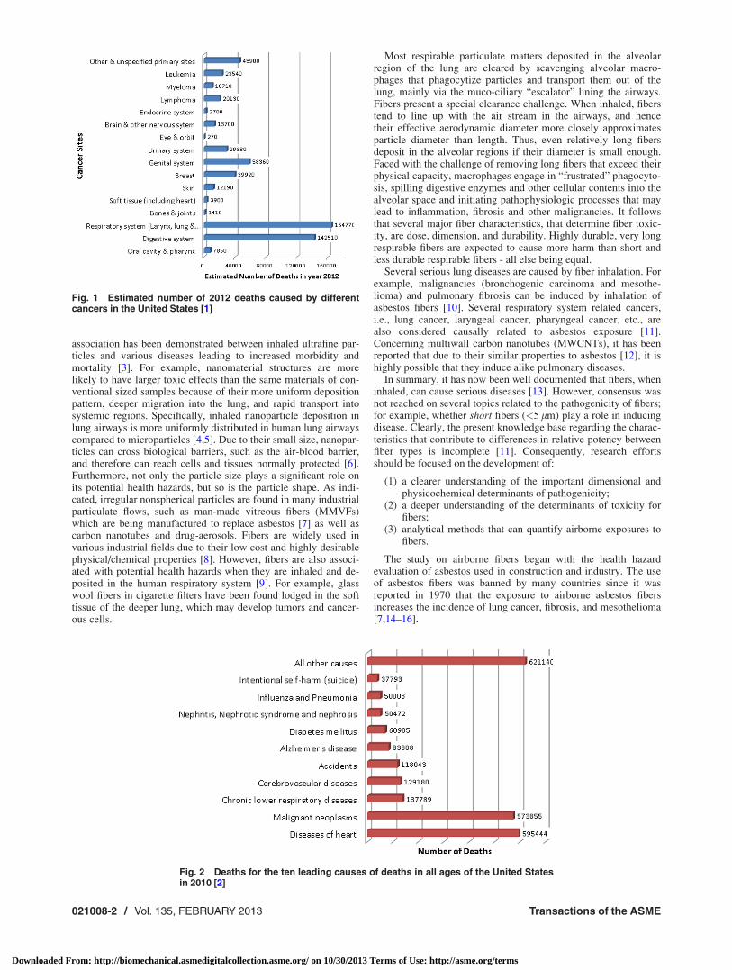
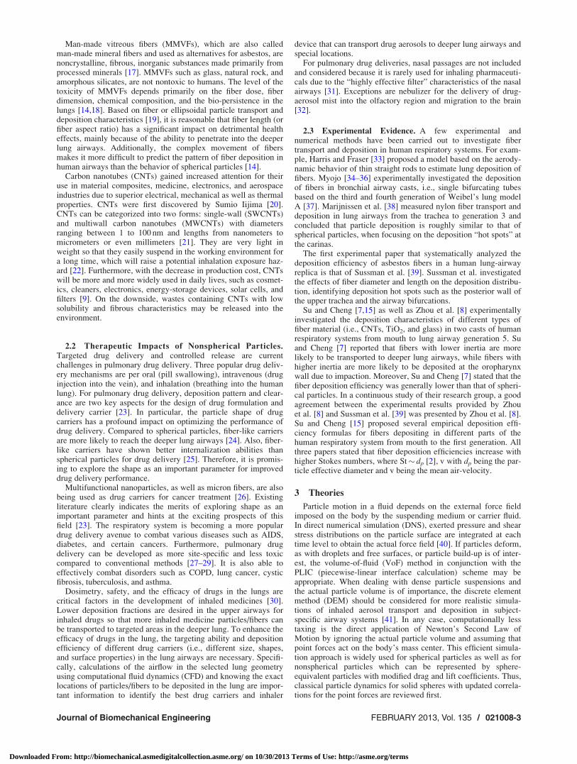
2.1 Particle Toxicology. Cancers of the respiratory system,especially lung cancer, account for more deaths than any othercancer in both men and women [1]. An estimated 160,340 deaths,making up 28% of all cancer deaths, are expected to occur in theUnited States in 2012 (see Fig. 1). Furthermore, according tothe statistical results shown in Fig. 2 [2], chronic lower respiratorydiseases, including chronic obstructive pulmonary diseases(COPDs), were thethird leading cause of deaths in the UnitedStates. Occupational or environmental exposure to cigarettesmoke, asbestos, and other fine-to-ultrafine toxic materials is byfar the most important risk factor for respiratory diseases.
Airborne particulate matter has been a health concern for manydecades. Although nanotechnology creates possibilities to producematerials with great benefits and improved characteristics onthe nano-to-micron scales, occupational exposures to those smallparticulates may adversely affect human health. In fact, an
1Corresponding author.Contributed by the Bioengineering Division of ASME for publication in the
JOURNAL OF BIOMECHANICAL ENGINEERING. Manuscript received November 9, 2012;final manuscript received December 3, 2012; accepted manuscript posted December22, 2012; published online February 7, 2013. Editor: Victor H. Barocas.
Journal of Biomechanical Engineering FEBRUARY 2013, Vol. 135 / 021008-1Copyright VC 2013 by ASME
Downloaded From: http://biomechanical.asmedigitalcollection.asme.org/ on 10/30/2013 Terms of Use: http://asme.org/terms
association has been demonstrated between inhaled ultrafine par-ticles and various diseases leading to increased morbidity andmortality [3]. For example, nanomaterial structures are morelikely to have larger toxic effects than the same materials of con-ventional sized samples because of their more uniform depositionpattern, deeper migration into the lung, and rapid transport intosystemic regions. Specifically, inhaled nanoparticle deposition inlung airways is more uniformly distributed in human lung airwayscompared to microparticles [4,5]. Due to their small size, nanopar-ticles can cross biological barriers, such as the air-blood barrier,and therefore can reach cells and tissues normally protected [6].Furthermore, not only the particle size plays a significant role onits potential health hazards, but so is the particle shape. As indi-cated, irregular nonspherical particles are found in many industrialparticulate flows, such as man-made vitreous fibers (MMVFs)which are being manufactured to replace asbestos [7] as well ascarbon nanotubes and drug-aerosols. Fibers are widely used invarious industrial fields due to their low cost and highly desirablephysical/chemical properties [8]. However, fibers are also associ-ated with potential health hazards when they are inhaled and de-posited in the human respiratory system [9]. For example, glasswool fibers in cigarette filters have been found lodged in the softtissue of the deeper lung, which may develop tumors and cancer-ous cells.
Most respirable particulate matters deposited in the alveolarregion of the lung are cleared by scavenging alveolar macro-phages that phagocytize particles and transport them out of thelung, mainly via the muco-ciliary “escalator” lining the airways.Fibers present a special clearance challenge. When inhaled, fiberstend to line up with the air stream in the airways, and hencetheir effective aerodynamic diameter more closely approximatesparticle diameter than length. Thus, even relatively long fibersdeposit in the alveolar regions if their diameter is small enough.Faced with the challenge of removing long fibers that exceed theirphysical capacity, macrophages engage in “frustrated” phagocyto-sis, spilling digestive enzymes and other cellular contents into thealveolar space and initiating pathophysiologic processes that maylead to inflammation, fibrosis and other malignancies. It followsthat several major fiber characteristics, that determine fiber toxic-ity, are dose, dimension, and durability. Highly durable, very longrespirable fibers are expected to cause more harm than short andless durable respirable fibers - all else being equal.
Several serious lung diseases are caused by fiber inhalation. Forexample, malignancies (bronchogenic carcinoma and mesothe-lioma) and pulmonary fibrosis can be induced by inhalation ofasbestos fibers [10]. Several respiratory system related cancers,i.e., lung cancer, laryngeal cancer, pharyngeal cancer, etc., arealso considered causally related to asbestos exposure [11].Concerning multiwall carbon nanotubes (MWCNTs), it has beenreported that due to their similar properties to asbestos [12], it ishighly possible that they induce alike pulmonary diseases.
In summary, it has now been well documented that fibers, wheninhaled, can cause serious diseases [13]. However, consensus wasnot reached on several topics related to the pathogenicity of fibers;for example, whether short fibers (<5 lm) play a role in inducingdisease. Clearly, the present knowledge base regarding the charac-teristics that contribute to differences in relative potency betweenfiber types is incomplete [11]. Consequently, research effortsshould be focused on the development of:
(1) a clearer understanding of the important dimensional andphysicochemical determinants of pathogenicity;
(2) a deeper understanding of the determinants of toxicity forfibers;
(3) analytical methods that can quantify airborne exposures tofibers.
The study on airborne fibers began with the health hazardevaluation of asbestos used in construction and industry. The useof asbestos fibers was banned by many countries since it wasreported in 1970 that the exposure to airborne asbestos fibersincreases the incidence of lung cancer, fibrosis, and mesothelioma[7,14–16].
Fig. 1 Estimated number of 2012 deaths caused by differentcancers in the United States [1]
Fig. 2 Deaths for the ten leading causes of deaths in all ages of the United Statesin 2010 [2]
021008-2 / Vol. 135, FEBRUARY 2013 Transactions of the ASME
Downloaded From: http://biomechanical.asmedigitalcollection.asme.org/ on 10/30/2013 Terms of Use: http://asme.org/terms
Man-made vitreous fibers (MMVFs), which are also calledman-made mineral fibers and used as alternatives for asbestos, arenoncrystalline, fibrous, inorganic substances made primarily fromprocessed minerals [17]. MMVFs such as glass, natural rock, andamorphous silicates, are not nontoxic to humans. The level of thetoxicity of MMVFs depends primarily on the fiber dose, fiberdimension, chemical composition, and the bio-persistence in thelungs [14,18]. Based on fiber or ellipsoidal particle transport anddeposition characteristics [19], it is reasonable that fiber length (orfiber aspect ratio) has a significant impact on detrimental healtheffects, mainly because of the ability to penetrate into the deeperlung airways. Additionally, the complex movement of fibersmakes it more difficult to predict the pattern of fiber deposition inhuman airways than the behavior of spherical particles [14].
Carbon nanotubes (CNTs) gained increased attention for theiruse in material composites, medicine, electronics, and aerospaceindustries due to superior electrical, mechanical as well as thermalproperties. CNTs were first discovered by Sumio Iijima [20].CNTs can be categorized into two forms: single-wall (SWCNTs)and multiwall carbon nanotubes (MWCNTs) with diametersranging between 1 to 100 nm and lengths from nanometers tomicrometers or even millimeters [21]. They are very light inweight so that they easily suspend in the working environment fora long time, which will raise a potential inhalation exposure haz-ard [22]. Furthermore, with the decrease in production cost, CNTswill be more and more widely used in daily lives, such as cosmet-ics, cleaners, electronics, energy-storage devices, solar cells, andfilters [9]. On the downside, wastes containing CNTs with lowsolubility and fibrous characteristics may be released into theenvironment.
2.2 Therapeutic Impacts of Nonspherical Particles.Targeted drug delivery and controlled release are currentchallenges in pulmonary drug delivery. Three popular drug deliv-ery mechanisms are per oral (pill swallowing), intravenous (druginjection into the vein), and inhalation (breathing into the humanlung). For pulmonary drug delivery, deposition pattern and clear-ance are two key aspects for the design of drug formulation anddelivery carrier [23]. In particular, the particle shape of drugcarriers has a profound impact on optimizing the performance ofdrug delivery. Compared to spherical particles, fiber-like carriersare more likely to reach the deeper lung airways [24]. Also, fiber-like carriers have shown better internalization abilities thanspherical particles for drug delivery [25]. Therefore, it is promis-ing to explore the shape as an important parameter for improveddrug delivery performance.
Multifunctional nanoparticles, as well as micron fibers, are alsobeing used as drug carriers for cancer treatment [26]. Existingliterature clearly indicates the merits of exploring shape as animportant parameter and hints at the exciting prospects of thisfield [23]. The respiratory system is becoming a more populardrug delivery avenue to combat various diseases such as AIDS,diabetes, and certain cancers. Furthermore, pulmonary drugdelivery can be developed as more site-specific and less toxiccompared to conventional methods [27–29]. It is also able toeffectively combat disorders such as COPD, lung cancer, cysticfibrosis, tuberculosis, and asthma.
Dosimetry, safety, and the efficacy of drugs in the lungs arecritical factors in the development of inhaled medicines [30].Lower deposition fractions are desired in the upper airways forinhaled drugs so that more inhaled medicine particles/fibers canbe transported to targeted areas in the deeper lung. To enhance theefficacy of drugs in the lung, the targeting ability and depositionefficiency of different drug carriers (i.e., different size, shapes,and surface properties) in the lung airways are necessary. Specifi-cally, calculations of the airflow in the selected lung geometryusing computational fluid dynamics (CFD) and knowing the exactlocations of particles/fibers to be deposited in the lung are impor-tant information to identify the best drug carriers and inhaler
device that can transport drug aerosols to deeper lung airways andspecial locations.
For pulmonary drug deliveries, nasal passages are not includedand considered because it is rarely used for inhaling pharmaceuti-cals due to the “highly effective filter” characteristics of the nasalairways [31]. Exceptions are nebulizer for the delivery of drug-aerosol mist into the olfactory region and migration to the brain[32].
2.3 Experimental Evidence. A few experimental andnumerical methods have been carried out to investigate fibertransport and deposition in human respiratory systems. For exam-ple, Harris and Fraser [33] proposed a model based on the aerody-namic behavior of thin straight rods to estimate lung deposition offibers. Myojo [34–36] experimentally investigated the depositionof fibers in bronchial airway casts, i.e., single bifurcating tubesbased on the third and fourth generation of Weibel’s lung modelA [37]. Marijnissen et al. [38] measured nylon fiber transport anddeposition in lung airways from the trachea to generation 3 andconcluded that particle deposition is roughly similar to that ofspherical particles, when focusing on the deposition “hot spots” atthe carinas.
The first experimental paper that systematically analyzed thedeposition efficiency of asbestos fibers in a human lung-airwayreplica is that of Sussman et al. [39]. Sussman et al. investigatedthe effects of fiber diameter and length on the deposition distribu-tion, identifying deposition hot spots such as the posterior wall ofthe upper trachea and the airway bifurcations.
Su and Cheng [7,15] as well as Zhou et al. [8] experimentallyinvestigated the deposition characteristics of different types offiber material (i.e., CNTs, TiO2, and glass) in two casts of humanrespiratory systems from mouth to lung airway generation 5. Suand Cheng [7] reported that fibers with lower inertia are morelikely to be transported to deeper lung airways, while fibers withhigher inertia are more likely to be deposited at the oropharynxwall due to impaction. Moreover, Su and Cheng [7] stated that thefiber deposition efficiency was generally lower than that of spheri-cal particles. In a continuous study of their research group, a goodagreement between the experimental results provided by Zhouet al. [8] and Sussman et al. [39] was presented by Zhou et al. [8].Su and Cheng [15] proposed several empirical deposition effi-ciency formulas for fibers depositing in different parts of thehuman respiratory system from mouth to the first generation. Allthree papers stated that fiber deposition efficiencies increase withhigher Stokes numbers, where St� dp [2], v with dp being the par-ticle effective diameter and v being the mean air-velocity.
3 Theories
Particle motion in a fluid depends on the external force fieldimposed on the body by the suspending medium or carrier fluid.In direct numerical simulation (DNS), exerted pressure and shearstress distributions on the particle surface are integrated at eachtime level to obtain the actual force field [40]. If particles deform,as with droplets and free surfaces, or particle build-up is of inter-est, the volume-of-fluid (VoF) method in conjunction with thePLIC (piecewise-linear interface calculation) scheme may beappropriate. When dealing with dense particle suspensions andthe actual particle volume is of importance, the discrete elementmethod (DEM) should be considered for more realistic simula-tions of inhaled aerosol transport and deposition in subject-specific airway systems [41]. In any case, computationally lesstaxing is the direct application of Newton’s Second Law ofMotion by ignoring the actual particle volume and assuming thatpoint forces act on the body’s mass center. This efficient simula-tion approach is widely used for spherical particles as well as fornonspherical particles which can be represented by sphere-equivalent particles with modified drag and lift coefficients. Thus,classical particle dynamics for solid spheres with updated correla-tions for the point forces are reviewed first.
Journal of Biomechanical Engineering FEBRUARY 2013, Vol. 135 / 021008-3
Downloaded From: http://biomechanical.asmedigitalcollection.asme.org/ on 10/30/2013 Terms of Use: http://asme.org/terms

3.1 Spherical Particle Dynamics. For a single particle inshear flow, the particle trajectory equation, i.e., Newton SecondLaw, can be expressed as [42]:
mpd~vp
dt¼X
~Fbody þX
~Fsurface þX
~Finteraction (1)
where
d
dt¼ @
@tþ~vp � r (2)X
~Fbody ¼ ~FBuoyancy þ ~FVM (3)X~Fsurface ¼ ~FD þ ~FPressure þ ~FBasset þ ~FSaffman þ ~FMagnus (4)
S~FInteraction ¼ ~FBM þ ~FParticle�particle þ ~FParticle�wall (5)
Equation (1) is a reduced form of the generalized Basset–Boussinesq–Oseen (BBO) equation discussed by Ref. [43]. Therelative importance of each term when compared to the drag forceis outlined in Table 1. Still, the BBO equation can be quite com-plex as it includes a wide range of length scales and time scales,as well as issues concerning turbulence, convection, settling, two-way coupling, collisions, aggregation, etc.
In this section, all expressions are based on the spherical parti-cle assumption. Newton’s second law is solved for the particle’strajectory in airflow fields, where multiple polydisperse particlescan be individually tracked by solving Eq. (1).
Drag force. To obtain precise motion of a spherical particle, anaccurate relationship between Reynolds number and drag force(i.e. drag coefficient) is required. The drag coefficient is intro-duced as:
CD ¼~FD
pd2p
4
1
2qf ~vp �~vf
� �~vp �~vf
�� ��� � (6)
Thus, the drag force on a spherical particle in “uniform Newtonianfluid flow” can be expressed as [44]:
~FD ¼1
2CD
pd2p
4qf ~vp �~vf
� �~vp �~vf
�� �� (7)
with assumptions that the pressure field is uniform and no acceler-ation is induced by the difference between vp and vf. Generally,the drag coefficient depends on particle shape and orientation,Reynolds number, and turbulence level, if any. For creeping flow(i.e., Rep <1), the Stokes drag force can be written as:
~FD ¼ 3plf dp ~vp �~vf
� �(8)
In nonuniform shear flows and for particles near a wall, drag-force corrections are necessary [44–46], as summarized below. Inall cases, the relative particle Reynolds number Rep is defined as:
Rep ¼vp!� vf
!�� �� � dp � qf
l(9)
Specifically, for solid spherical particles,
CD ¼
24
Rep; 0 < Rep < 1
24
Re0:646p
1 < Rep < 400
8>><>>: (10)
For spherical droplets,
CD ¼3:05 783j2 þ 2142jþ 1080ð Þ
60þ 29jð Þ 4þ 3jð Þ Re�0:74p (11)
where j ¼ lp=lf . Equation (11) holds for 4 <Rep <100. Addi-tional correlations were summarized by Loth [47]. For example,White [48] proposed a correlation for CD in the form of:
Table 1 The relative importance of forces compared to Stokes drag force
Name ofthe force Origin of the force
The relative importance comparedto stokes drag force
Negligibility compared tostokes drag force
F!
Basset It is a result from the acceleration of thefluid around the particle, i.e., a temporalvelocity changes with time. It accounts forthe effects of past acceleration on theresistance.
RBasset ¼~FBasset
FD
���������� �
ffiffiffiffiffiffiffiffiffiffiqf
qp
ss
t
rss ¼
qpd2p
18lf
qf � qp and ss is relatively small for
submicron particles, it can be neglected
F!
PressCaused by the pressure gradient
RPressure ¼~FPressure
FD
���������� � d2
prpFor submicron particles, since dp is smalland the pressure gradient around the particlecan be considered very small, it can beneglected.
F!
FaxenThe near-wall correction term to the Stokesdrag force caused by the nonuniform shearfield especially near the wall
RFaxen ¼~FFaxen
~FD
���������� � dp
L
� 2 For submicron particles, since dp is small, itcan be neglected
F!
MagnusLift force induced by the particle rotation
RMagnus ¼~FMagnus
FD
���������� � qf d2
p
lf
~xj jFor submicron particles, since dp is small, itcan be neglected
F!
BuoyancyCaused by the buoyancy and gravity
Rbuoyancy ¼~Fbuoyancy
FD
���������� � qf � qp
� �d2
p
lf v!f � v!p
� � For submicron particles, it is not neglected;while for nanoparticles, it is neglected.
F!
OthersIncluding Brownian motion induced force,contact force between particles, etc.
N/A For submicron particles, Brownian motionforce can be neglected; while fornanoparticles, Brownian motion force needto be considered.For dilute particulate suspensions, contactforce between particles can be neglected; fordense particulate suspensions, contact forcebetween particles need to be considered.
021008-4 / Vol. 135, FEBRUARY 2013 Transactions of the ASME
Downloaded From: http://biomechanical.asmedigitalcollection.asme.org/ on 10/30/2013 Terms of Use: http://asme.org/terms
CD ¼24
Repþ 6
1þffiffiffiffiffiffiffiffiRep
p þ 0:4 Rep < 2� 105 (12)
A generally more accurate sub-critical expression (being within6% of experimental data) was given by Clift and Gauvin [49] as:
CD ¼24
Rep1þ 0:15Re0:687
p
�� �þ 0:42
1þ 42500
Re1:16p
Rep < 2 (13)
Buoyancy. The buoyancy force executed on the particleimmersed in the fluid can be expressed as:
~FBuoyancy ¼ qf � qp
� �Vp �~g (14)
Pressure gradient force. The effect of the local pressuredistribution gives rise to a force in the direction of the pressuregradient. Therefore, the pressure gradient force ~Fp can be writtenas [50,51]:
~FPressure ¼p6
d3prp (15)
The pressure gradient force is significant only in high-Reynoldsnumber flows.
Virtual mass force. The virtual mass force is a result of theaccelerating fluid surrounding the accelerating particle. It has atendency to keep the particle from being accelerated in any direc-tion. The origin of the force is that the fluid will gain kineticenergy at the expense of the work done by an accelerating sub-merged particle. It can be expressed as:
~FVM ¼1
2qf Vp
d~vf
dt� d~vp
dt
� (16)
of which the magnitude is one half of the inertia force for the fluidwith the same volume of the particle. It is worth noting that ~Fvm
can be neglected if the relative acceleration, i.e., jðd~vf =dtÞ�ðd~vp=dtÞj is small. Expressions of the virtual mass force wereproposed for cylinders and ellipsoids by Loewenberg [52].
Basset force. The Basset force is due to the lagging boundarylayer development with changing relative velocity when particlesmove through a fluid. It accounts for viscous effects and addressesthe temporal delay in boundary layer development as the relativevelocity changes with time. It can be rigorously derived from themotion of a single accelerating sphere in the Stokes regime in aquiescent fluid as:
~FBasset ¼3
2d2
p
ffiffiffiffiffiffiffiffiffiffiffiffipqf lf
p ðt
0
d~vf
ds� d~vp
dsffiffiffiffiffiffiffiffiffiffit� sp
0B@
1CAds (17)
The Basset force accounts for the effects of past acceleration onthe resistance. In the expression, (–s) represents the time elapsedsince past acceleration from 0 to t [53]. Therefore, this force isdue to the diffusion of the vorticity around spherical particles anddecays as t�1/2, which is typical of diffusion processes. It is alsocalled the history term/force [43].
For Rep >1, i.e., beyond the Stokes regime, ~FBasset can be modi-fied by introducing a correction factor. The magnitude ratiobetween ~FBasset and ~FD can be written as [53]:
RBasset ¼~FBasset
FD
���������� ¼
ffiffiffiffiffiffiffiffiffiffiffiffiffiffiffi18
p
qf
qp
ss
t
s(18)
where ss is the Stokes relaxation time defined as:
ss ¼qpd2
p
18lf
(19)
~FBasset can be neglected if qf � qp or the Stokes relaxation timeis relatively small compared to the time duration from 0 to t.
Lift forces. The total lift coefficient can be defined as [54]:
CL ¼FL
1
8qf ~vf �~vp
�� ��2pd2p
(20)
The total lift force is composed of forces due to different physicalmechanisms.
(1) Saffman Force.The Saffman Force is a lift force due to local flow velocitygradients (i.e., shear flows). For small particles translatingin a linear unbounded shear field, the expression for theSaffman force’s magnitude can be expressed as follows forRep < 1:
~FSaffman
�� �� ¼ Klf
4~vf �~vp
�� ��d2p
ffiffiffiffiffiffiffiffiffiffiffiffiffiffiffiffiffiffiffiffiffiffiffiffiffiffiffiffiffi1
�f
@ ~vf �~vp
� �@y
��������
s
� sign@ ~vf �~vp
� �@y
� (21)
K¼ 1.615 is a constant determined based on a numericalintegration for creeping flows at low shear rates [55]. Thedirection of ~FSaffman is either in positive y-direction or nega-tive y-direction. For higher Rep values or near-wall regions,the expression of the Saffman force needs to be modified.For creeping flows at low shear rates, the magnitude ratiobetween ~FMagnus and ~FD can be written as [53]:
RSaffman ¼~FSaffman
FD
���������� ¼ 1:615dp
3p
ffiffiffiffiffiffiffiffiffiffiffiffiffiffiffiffiffiffiffiffiffiffiffiffiffiffiffiffiffi1
�f
@ ~vf �~vp
� �@y
��������
s(22)
It can be neglected when the shear rate is very small or Rep
is very small.(2) Magnus Force.
The Magnus force is a rotation-induced lift force acting onthe particle. The expression for such a force is:
~FMagnus ¼1
8pd2
pqf ~x� ~vf �~vp
� �(23)
where ~x is the angular velocity vector of the particle.The magnitude ratio between ~FMagnus and ~FD can be writtenas [53]:
RMagnus ¼~FMagnus
FD
���������� ¼ d2
p
24
qf
lf
~xj j (24)
Therefore, for small particles (e. g., nanoparticles) the Mag-nus force can be neglected.
(3) Wall-Induced Lift Force.The hydrodynamic force on a particle moving in a linearshear flow close to a wall is of fundamental significance influid dynamics. The effect of the wall is the strongest whenthe particle is in contact, while the wall effect decaysrapidly with distance from the wall [56]. Specifically, thewall-induced lift force is due to two possible mechanisms[46]: (i) the presence of a wall near a particle will break upthe axisymmetry of the wake vorticity field, which resultsin an effective lift force on the particle directed away fromthe wall; (ii) flow relative to the particle will acceleratefaster in the gap between the particle and the wall rather
Journal of Biomechanical Engineering FEBRUARY 2013, Vol. 135 / 021008-5
Downloaded From: http://biomechanical.asmedigitalcollection.asme.org/ on 10/30/2013 Terms of Use: http://asme.org/terms
than further away. The resulting low pressure in the gap(see Bernoulli principle) will induce a lift force directed to-ward the wall.
Although the wall-induced asymmetry of the flow also inducesrotational motion of the particle, many papers claimed that the liftforce induced by such a rotation can be neglected when comparedto the Saffman force [45,55].
Brownian motion force. FBM;i is the Brownian motion force onthe particle in the i-th direction which can be modeled as a Gaus-sian white noise process [57].
FBM;i ¼ fi
ffiffiffiffiffiffiffipS0
Dt
r(25)
where fi are three zero-mean, unit-variance-independent Gaussianrandom numbers, Dt is the time step, and S0 is presented asfollows:
S0 ¼216 � tf � jB � T
p2qf d5p
qp
qf
!2
Cc
(26)
in which T is the bulk temperature of the mixture, Cc is the Cun-ningham correction factor:
Cc ¼ 1þ 2kdp
1:257þ 0:4 exp � 1:1dp
2k
� � (27)
and jB is the Boltzmann constant.
Particle–particle interaction forces. Particle–particle interac-tion forces are necessary to be considered for dense particle sus-pensions. Hard sphere model and soft sphere model are the twomodels which are widely used for numerical simulations [40].
Drag force corrections. For particles in unbounded linear shearflows, the drag force on the particle is not significantly influencedcompared to the situation in uniform flows [45]. However, in non-uniform shear field, an additional term for correction, i.e., theFaxen force [44], has to be considered:
~FFaxen ¼ lf pd3
p
8r2~vf (28)
Zeng [46] indicated that when particles move parallel to a wall,the drag coefficient for all separations between particle and wallcan be curve-fitted for all Rep-numbers as:
CD ¼24
Rep1þ 0:15Re0:687
p
�1þ 0:7005exp �2:1
L
dp� 0:5
� � � (29)
where L is the distance between the particle and the wall.
Lift force corrections. For Saffman’s derivation [55], the liftcoefficient can be expressed as:
CL ¼ 5:816a�
Rep
� 12
�0:875a� þ 2x� (30)
Where a* is the dimensionless shear rate of the fluid:
a� ¼ dp
2 ~vf �~vp
�� �� @vf
@y(31)
And x* is the dimensionless rotational angular speed of theparticle
x� ¼ dp
2 ~vf �~vp
�� ��x (32)
As mentioned, Saffman’s expression is only suitable for creep-ing flow. Specifically, experiments [54] suggested that the liftforce acts towards the lower-fluid-velocity side from the higher-fluid-velocity side for Rep �1. The direction of particle move-ment is exactly opposite to Saffman’s expression. McLaughlin[58] extended Saffman’s theory to larger Rep numbers. Dandy andDwyer [59] numerically studied the drag and lift forces acting ona stationary sphere in a uniform shear flow for 0.1 <Rep <100.Cherukat et al. [60] investigated spherical particles movingparallel near wall and concluded that the presence of the solidboundary and a large velocity gradient can give rise to a lift forcethat can affect the trajectory of the aerosol particles.
Based on the theoretical results of Saffman [55] and numericalresults obtained by Dandy and Dwyer [59], Mei [61] proposedan expression for the shear lift force on a particle withoutrotation:
FL
Fsaffman
¼1� 0:3314a�
12
�exp �Rep
10
� þ 0:3314a�
12; Rep 40
0:0524 a�Rep
� �12; 100 > Rep > 40
8><>: (33)
Kurose and Komori [54] proposed new correlations for the liftcoefficient CL in linear shear flow, considering rotational sphericalparticles (1<Rep< 500):
CL Rep; a�;x�
� �¼ K0a
�0:9 þ K1a�1:1
þ K2 þ K3a� þ K4a
�2:0 þ K5a�9:5� �
x� (34)
where K0 to K5 are constants changing with Rep which can befound in the paper by Kurose and Komori [54] Equation (34) issuitable for L> 2dp. Zeng [45] proposed a CL-expression for aparticle touching the wall (L¼ 0.5dp) as follow:
CL Rep; a�;x�
� �¼ K0a
�0:9 þ K1a�1:1
þ K2 þ K3a� þ K4a
�2:0 þ K5a�9:5� �
x� (35)
Experimental and numerically studies of the near-wall and non-creeping flow effects on lift forces are ongoing.
3.2 Nonspherical Particle Dynamics Theory. Fibers areparticles that have one dimension significantly longer than its othertwo dimensions [62]. Numerous studies have demonstrated that thefiber aspect ratios as well as fiber durability are critical factorsinvolved in pathogenicity. Therefore, it is important to accuratelydescribe the orientation effect of fibers caused by their rotations.Other than a fiber’s translational equation, i.e., Newton’s Secondlaw, Eulerian rotational equations must be introduced and solved inorder to predict fiber orientation when transported in shear flows.
Complete Numerical Simulation (CNS) Methods. Computa-tional studies of gas-solid flows go back to the very beginning
021008-6 / Vol. 135, FEBRUARY 2013 Transactions of the ASME
Downloaded From: http://biomechanical.asmedigitalcollection.asme.org/ on 10/30/2013 Terms of Use: http://asme.org/terms

of CFD [42,44]. However, direct numerical simulation (DNS)methods for multiphase flow have emerged as a major researchtool only during the last 20 years [63]. The definition of DNS formultiphase flow is a little confusing. Actually, DNS is a categoryof simulations which is more often associated with detailedturbulence modeling of the carrier phase with point particleapproximations for the dispersed phase [40,63]. Concerning turbu-lent flow, DNS is a numerical technique to obtain 3D, time-dependent solutions to the nonlinear Navier–Stokes equations[64]. The solution should capture all the scales of turbulence,ranging from large-scale structures to spatial and temporalKolmogorov-scale turbulence in the flow without employing anyempirical closure models.
In this section, detailed numerical simulation of multiphaseflows is equivalent to Complete Numerical Simulation (CNS) toavoid confusion with DNS for numerical turbulence analysis[40]. Specifically, CNSs are numerical techniques where theNavier–Stokes equations are applied to finite-size particles insteadof introducing “point particle” forces. Joseph [65] indicated thatCNS methods for solid-liquid flows are ways of solving the initialvalue problem for the motion of particles in fluids exactly. Particlemovement is described by Newton’s laws under the action ofhydrodynamic forces computed from the numerical solution of thefluid flow equations.
Characteristics of CNS methods for multiphase flows can bedescribed as follows. Ideally, all surface and exchange forcesshould be accurately integrated from the fluid-particle andparticle–particle interactions to obtain the velocity, pressure, andstress fields surrounding each particle [42]. Specifically, becausescales of meshes for CNS methods are much smaller than thescales of particles, forces such as drag force, lift force, andinteraction forces between particles can be obtained directly byintegrating the shear stress and pressure distributed alongthe particle surfaces without employing any empirical correla-tions, such as drag and lift coefficients. Therefore, compared toEuler–Euler models and Euler–Lagrange models, CNS can accu-rately describe motions of particles with arbitrary shapes on the“meso-scale.” Clearly, CNS of multiphase flows is able to producedetailed results and hence improved knowledge, e. g., the nonlin-ear and geometrically complicated phenomena of particle–particleand particle–wall interactions [66]. Compared to the Euler-Eulermethod and Euler-Lagrange method, CNS methods have severaladvantages:
(1) The motion of the fluid and that of the solid particles arefully coupled (i.e., two-way coupling). Hence the interac-tions of both the fluid and the individual solid particles canbe calculated.
(2) Hydrodynamic forces and torques imposed on particles canbe obtained by direct integration of the shear stress andpressure distributed along the particle surface without anyempirical correlations.
However, the computational cost of the CNS method is still toohigh for engineering application, especially for a large number ofparticles in light of the current computational resources available[40]. Thus, in recent years, simplified CNS methods for fluid-solidflows were developed. Several popular approaches, whichdiffer in how to deal with the moving boundaries of the particles(i.e., employing moving meshes), are the arbitrary Lagrangian–Eulerian (ALE) method [66], distributed Lagrange-multiplier(DLM) method [67], and the lattice Boltzmann method (LBM)[68,69].
“Particle Mover” algorithms are essential in realizing CNSmethods. Two different kinds of particle movers are widely used:one is based on body-fitted, moving unstructured grids, e.g., theALE method; another is based on fixed structured grids overwhich bodies move by a technique involving a system ofLagrange multipliers, e.g., the DLM method. Taking the ALE andDLM methods as examples, details of direct numerical simula-tions are presented as follows.
(i) Arbitrary Lagrangian-Eulerian Technique. The ArbitraryLagrangian–Eulerian (ALE) technique was first developed by Huet al. [66]. It can be used to solve particle motions in 2D and 3Dflow fields and it can handle particles of different sizes, shapesand materials. In addition, ALE uses a technique based on a com-bined formulation of the fluid and particle momentum equations,together with a moving, unstructured, finite-element mesh tech-nique to deal with the movement of the particles. The hydrody-namics forces acting on the solid particles are directly computedfrom the fluid flow field, where the motion of the fluid flow andsolid particle trajectories are carefully coupled. The ALE methodis also categorized as a boundary-fitted method. Specifically, ALEconsiders the motion of N rigid solid particles in an incompressi-ble fluid. X0(t) represents the domain occupied by the fluid at agiven time instant t, t 2 0; T½ , and Xi(t) as the domain occupiedby the ith particle (i¼ 1,2, …, N), where @X0(t) and @Xi(t) repre-sent the boundaries of X0(t) and Xi(t) (see Fig. 3).
The governing equations for the fluid motion in X0(t) can beexpressed as follows
Continuity Equation:
r � vf!¼ 0 (36)
Momentum Equation:
qf
Dvf!
Dt¼ qf f!þr � r (37)
For Newtonian fluids, the stress tensor r is:
r ¼ �p I½ þ lf rvf!� �Tþrvf
!h i(38)
where p is the pressure and lf is the viscosity of the fluid.For solid particles of arbitrary shapes, the governing equations
differ for each particle i.Translational Equation:
mp;id vp;i�!dt¼ F!
body þ F!
surface ¼ F!
body �ð@XiðtÞ
r � n!dS (39)
Eulerian Rotational Equation:
Ti!¼ �
ð@XiðtÞ
x!p � x!cp;i
� �� r � n!� �
dS (40)
The index i represents different particles; n! is the unit normalvector on the surface of the particle pointing into the particle, Ti
!are the hydrodynamic torques acting on the particle i, and x!cp;i isthe centroid of particle i. No-slip boundary conditions are imposedat particle–fluid interfaces, i.e.,
Fig. 3 Two-dimensional finite-element mesh in channel flowusing the ALE method [66]
Journal of Biomechanical Engineering FEBRUARY 2013, Vol. 135 / 021008-7
Downloaded From: http://biomechanical.asmedigitalcollection.asme.org/ on 10/30/2013 Terms of Use: http://asme.org/terms

v!f
��@XiðtÞ¼ v!p;i þ x!p;i � x!p;i � x!cp;i
� �(41)
For the fully explicit scheme of the ALE method [70], the solutionprocedure can be presented as follows:
• Initialization• Update particle positions• Re-meshing• Update flow field, particle velocities, particle angular
velocities• If the time is less than a specified time, repeat from second
step on; otherwise, stop
One distinct weakness of the ALE method in its various formsis the need to re-mesh. This prospect alone is a great drain oncomputational resources and slows the solution process. There-fore, fictitious-domain methods were introduced which can avoidre-generation of the mesh for each time step.
(ii) Distributed Lagrangian Multiplier Method. The distrib-uted Lagrange multiplier (DLM) method is based on thefictitious–domain method. The fictitious domain is derived fromthe idea that fluid fills the space inside of the particles as well asoutside. Since fluid fills the whole flow domain, including particlevolumes, a simple fixed finite element mesh can be generated tosolve for the velocities of the fluid and the particles. As the meshdoes not need to be refreshed in every time step, it is much moreefficient when compared to the ALE method. The particle istracked by using boundary control points that are on the particleboundary and move with the particle. The grid (see Fig. 4) doesnot conform to the shape of the particle. The nodes that are insidethe particle boundary have their calculated velocity, i.e., thevelocity which at that point in the particle would have due to arigid body motion. Since fluid occupies the region of the particle,the Navier–Stokes equations must be solved to obtain velocityvalues for any point inside or on the surface of the particle. Thebody force term in the Navier–Stokes equations is multiplied by aconstant corresponding to that particular position that will yield avelocity due to rigid body motion.
The equations that are solved for the ALE method are alsosolved for the DLM method. Since the particle is now a fictitiousfluid in this method, the motion on the particle boundary and
inside the particle has to match the rigid body motion. To do this,Lagrange multipliers are introduced to multiply the forces on thefluid elements of the particle to make them behave like they arepart of a rigid body. These multipliers represent the additionalbody force needed to maintain rigid-body motion inside the parti-cle boundary. The idea of the distributed Lagrangian multipliers isthat the particle is a continuous system and each element must bemultiplied by a different constant to properly meet the rigid bodymotion constraint [65].
Although there is no need for updating meshes at each timestep when compared to the ALE method, the computational effortrequired to solve the equations of motion is higher and thereforesomewhat limits the number of particles to be considered.
Euler–lagrange methods. Euler–Lagrange (E–L) methods,which are also called discrete phase models (DPMs), provide adirect description of the particulate flow by tracking the motion ofindividual particles [70]. The continuous phase, i.e., fluid flow isgoverned by continuum equations which can be solved in theEulerian frame. For spherical particles, their motion is governedby Newton’s Second Law (see Eqs. (1)–(5)) which employs em-pirical correlations for hydraulic forces acting on the particles.For dilute particle suspensions, one-way coupling is assumedwhich implies that the particle motion is influenced by the flowfield, while the flow field is not disturbed by the presence of theparticles [44]. Two types of E–L methods are employed for calcu-lating transport and deposition of a nonspherical particle, i.e., theeffective diameter method and the E–L method enhanced withEuler’s rotational equations.
(1) Effective Diameter Method.Using the “effective diameter method,” nonspherical particles
are considered spherical with a parameter-equivalent diameter.Several definitions for “effective diameter” can be found in theliterature. They include [19] the equal projected circular areadiameter, the equal volume diameter, Stokes equivalent diameter,and aerodynamic diameter. As can be expected, specific empiricalcorrelations for drag force, lift force, and other forces acting onnonspherical particles have to be established.
The effective diameter method can be used as a quick analysistool for the approximate analysis of nonspherical particle transportand deposition provided that:
• a proper effective/equivalent diameter for nonspherical par-ticles is employed; and
• proper correlations for hydrodynamic forces acting on non-spherical particles are used
Suitable nonspherical hydrodynamic force correlations are sum-marized as follows:
(i) Drag Coefficient CD Correlations for Non-SphericalParticles. Introducing the shape factor parameter (i.e., sphericity)into the correction of drag coefficient and lift coefficient fornonspherical particle, the shape effect can be captured. Sphericitywas first introduced by Wadell [71] and is defined as the ratio ofthe surface area As of a sphere having the same volume Vp as theparticle and the actual surface area of the particle Ap:
W ¼ As
Ap¼
p1=3 6Vp
� �2=3
Ap¼
23
2b
� 23
1þ 2b(42)
For example, for cylindrical particles of height h and radius r, thesphericity is:
Wc ¼p1=3 pr2hð Þ2=3
2pr r þ hð Þ ¼rh2ð Þ1=3
2 r þ hð Þ (43)
For ellipsoidal particles with semi-major axis length a and semi-minor axis length b, the sphericity is:Fig. 4 Fixed triangular grid used in DLM computations [65]
021008-8 / Vol. 135, FEBRUARY 2013 Transactions of the ASME
Downloaded From: http://biomechanical.asmedigitalcollection.asme.org/ on 10/30/2013 Terms of Use: http://asme.org/terms

We ¼2ffiffiffiffiffiffiffiab23p
aþ b2ffiffiffiffiffiffiffiffiffiffiffiffiffiffiffia2 � b2p ln
aþffiffiffiffiffiffiffiffiffiffiffiffiffiffiffia2 � b2p
b
! (44)
Other parameters (see Table 2) which can describe the shape fac-tors of nonspherical particles were summarized by Gabitto andTsouris [72].
Additionally, crosswise sphericity W? is defined as the ratiobetween the cross-sectional area of the volume equivalent sphereand the projected cross-sectional area of the considered particleperpendicular to the flow [73]. Furthermore, lengthwise sphericityWk is defined as the ratio between the cross-sectional area of thevolume equivalent sphere and the difference between half thesurface area and the mean longitudinal (i.e. parallel to the flowdirection) projected cross-sectional area of the consideredparticle.
Analytical solutions for the drag coefficient of a particleonly exist for spheres and spheroids [73] in creeping flow (i.e.,Rep� 1). For higher particle Reynolds numbers or more compli-cated flow field, drag coefficients can only be determined byexperiments or numerical simulations. In creeping flow, dragcoefficients for all bodies decrease inversely proportional to theparticle Reynolds number Rep.
A simple correlation of CD was proposed by Leith [74] for non-spherical objects in creeping flow as:
CD ¼8
Rep
1ffiffiffiffiffiffiffiW?p þ 16
Rep
1ffiffiffiffiWp (45)
Based on experimental curve fitting, Haider and Levenspiel[75] proposed the correlation:
CD ¼24
Rep1þ A � ReB
p
�þ C
1þ D
Rep
(46)
where
A ¼ exp 2:3288� 6:4581 �Wþ 2:4486 �W2� �
(47a)
B ¼ 0:0964þ 0:5565 �W (47b)
C ¼ expð4:9050� 13:8944 �Wþ 18:4222 �W2 � 10:2599 �W3Þ(47c)
D ¼ expð1:4681þ 12:2584W� 20:7322W2 þ 15:8855W3Þ(47d)
Such a correlation is used by ANSYS FLUENT 14.0 as a default forthe nonspherical drag law. However, Gabitto and Tsouris [72]stated that Haider and Levenspiel’s correlation showed relativelypoor accuracy for particles with W< 0.67 and fitted for spheres,isometric solids, and disks with a 5.8% root-mean-square (RMS)deviation.
Ganser [76] proposed an expression for nonspherical particledrag coefficient in the form of:
CD ¼24
RepK1K2
1þ 0:1118 RepK1K2
� �0:6567h i
þ 0:4305
1þ 3305= RepK1K2
� � (48)
where
K1 ¼ dprojp;eff= 3dvol
p;eff
�þ 2= 3W0:5
� � ��1
(48a)
K2 ¼ 101:8148 � log Wð Þ0:5743
(48b)
dprojp;eff is the equal projected area circle diameter normal to the flow
direction:
dprojp;eff ¼
ffiffiffiffiffiffiffiffiffiffiffiffiffiffiffi4Ap;n=p
q(49)
dvolp;eff is the equal-sphere volume diameter. Chhabra et al. [77]
compared CD correlations for nonspherical particles with experi-mental data (0.09<W< 1 and 1 e-4<Rep< 5e5). It was indi-cated that the correlation proposed by Ganser [76] is moreaccurate (the mean error is 16%) than Haider and Levenspiel [75]and three other correlations [78–80].
A more realistic drag coefficient correlation for cylindrical par-ticles in an arbitrary direction was proposed by Fan et al. [81]:
CD cos a ¼ 24
Rep
� 0:006983þ 0:6224 Re�1:046
p
� qp
qf
!�1:537
� Ar�ð Þ0:8524(50)
Table 2 Shape factors for non-spherical particles [72]
Shape factor name Definition Pros and Cons
Volumetric shape factor (k) k ¼ Vp=d3proj;p where dproj;p is the projected area
diameter defined as: dproj;p ¼ffiffiffiffiffiffiffiffiffiffiffiffiffiffiffiffiffiffiffi4Aproj;p=p
pwhere Aproj,p
is the projected area of the particle according to itsorientation
Aproj,p is a difficult parameter to determine because itdepends on the orientation of the particle.
Degree of sphericity (W) W ¼ As=Ap where As is the surface of a sphere havingthe same volume as the particle, and Ap is the actualsurface area of the particle
Ap is difficult to calculate for particles with irregularshape except for ellipsoidal, cylindrical, and othernon-spherical shapes which can be described bymathematical functions.
Degree of circularity (wc) wc ¼ PS=Pproj;p where Ps is the perimeter of a spherewith equivalent projected area, and Pproj,p is theprojected perimeter of the particle.
Compared to the degree of sphericity, the circularitycan be determined from microscopic or photographicobservation.
Aspect ratio (b) For ellipsoidal particle: b ¼ bp=ap For cylindricalparticle: b ¼ L=dp
The aspect ratio can only be used for axisymmetricparticles, or else, it is inadequate to describe the shapeof the particles.
Shape parameter (R) R ¼ Ap=Aproj;p The shape parameter R is only adequate foraxisymmetric particles with creeping flow parallel tothe axis of symmetry.
Journal of Biomechanical Engineering FEBRUARY 2013, Vol. 135 / 021008-9
Downloaded From: http://biomechanical.asmedigitalcollection.asme.org/ on 10/30/2013 Terms of Use: http://asme.org/terms

Here a is the angle between the major axis of the cylinder and thedirection perpendicular to the flow direction and Ar* is the modi-fied Archimedes number, which is defined as:
Ar� ¼g � d3
p � qp � qf
� �2
l2f
(51)
Fan et al.’s [81] correlation apparently has an accuracy of 9.4%under the conditions of aspect ratio 4 <b <50, particle density1125 kg/m3< qp< 8000 kg/m3, and Rep< 40.
Tran-Cong et al. [82] introduced a surface-equivalent spherediameter:
dareap;eff ¼
ffiffiffiffiffiffiffiffiffiffiffiffiffi4Ap=p
q(52)
where Ap is the particle surface area. They also proposed a particlecircularity (or surface sphericity) c:
c ¼pdarea
p;eff
Pp(53)
where Pp is the projected perimeter of the particle in its directionof motion. The drag coefficient for nonspherical particles is thengiven for 0.15<Rep< 1500, 0.4< c< 1.0, 0.8< ðdarea
p;eff=dvolp;effÞ
< 1.5 as:
CD ¼24
Rep
dareap;eff
dvolp;eff
!1þ 0:15ffiffiffi
cp
dareap;eff
dvolp;eff
Rep
!0:68724
35
þ0:42
dareap;eff
dvolp;eff
!2
ffiffifficp
1þ 4:25� 104darea
p;eff
dvolp;eff
Rep
!�1:1624
35
(54)
Loth [47] took into account the orientation effect of spheroidparticles by measuring CD in three axisymmetric axial directions.Due to the linearity of the drag in creeping flow conditions, thedrag force can be obtained based on a simple combination of theindividual components in three axisymmetric axial directions fora spheroid particle in an arbitrary direction towards the flow.However, for higher Rep numbers, the linear assumption may notbe validated. Loth [47] also provided Stokes correction factors forspheroids of different aspect ratios in different directions.
Based on empirical data for fixed and freely falling particles,Hoelzer and Sommerfeld [73] came up with a CD expression fornonspherical particles:
CD ¼8
Rep
1ffiffiffiffiffiffiwk
q þ 16
Rep
1ffiffiffiffiw
p þ 3
Rep
1ffiffiffiffiffiffiffiffiffiw3=4
q þ 0:42100:4 � log Wð Þ0:2 1
W?
(55)
Equation (55) accounts for the particle orientation over the entirerange of Reynolds numbers [73].
(ii) Lift Coefficient Corrections for Non-Spherical Particles.The theoretical and empirical predictions for the lift coefficientare very limited compared to the information available for dragcoefficients. The usual assumption has been to assume that thelift is proportional to the drag and that the dependence with orien-tation is given by the so-called “cross-flow principle” as suggestedby Hoerner [83]:
CL
CD¼ sin2 ai � cos ai (56)
where the incidence angle ai between the flow direction and thelong axis of the fiber-like particle is shown in Fig. 5.
A more “accurate” correlation for the ratio between CL and CD
was proposed by Mando and Rosendahl [84] as follows:
CL
CD¼ sin2 ai � cos ai
0:65þ 40Re0:72p
30 < Rep < 1500 (57)
However, Mao [85] summarized that the experimental data of thelift force is not sound and hence there is no generally acceptablecorrelation for the lift coefficient.
Corrections of forces for nonspherical particles can improve theaccuracy of numerical simulation results when using the effectivediameter method. However, in order to completely capture theorientation effect on the transportation and deposition of non-spherical particles, additional equations, i.e., the Eulerian equa-tions for rotational motion of the rigid body, are necessary. Thus,the Euler–Lagrangian with Euler rotational equation method isnow introduced.
(1) Euler–Lagrangian with Euler Rotational Equation Method(EL–ER).
This approach is a good compromise between numericalsimulation accuracy and computational cost for simulatingnonspherical particle transport and deposition. Based on theEuler–Lagrange method, the Eulerian rotational equations fornonspherical particles are solved with user-enhanced programs[86]. It is worth emphasizing that the EL–ER method employed inthe present study is a one-way coupled method which may not beable to accurately predict dense particle suspensions due to thelack of particle-particle interaction representation (see Sec. 4).
The details of this method are shown as follows:In order to build the computational model for ellipsoidal parti-
cle and fiber transport and deposition in different flow fields, theEuler–Lagrange method is employed. Three different Cartesiancoordinates are introduced as well as Euler’s quaternions todescribe the particle dynamics. The governing equations of thecontinuous phase as well as the translation equations for ellipsoi-dal particles are in the global coordinate frame, while rotationalequations for ellipsoidal particles are in a body-fixed coordinateframe (see Figs. 6 and 7). Transformation matrices between differ-ent coordinates in terms of Euler’s quaternions are introduced aswell.
The transformation from a given Cartesian coordinate system toanother one can be carried out by means of three successiverotations performed in a specific sequence [87]. The Euler angles(u, h, w) are then defined as the three successive angles of rota-tion. The rotation sequence is as follows (see Fig. 6):
(a) Rotating the initial system of xyz-axes by an angle u coun-terclockwise about the z-axis to generate the ngf-system.Fig. 5 Incidence angle ai of nonspherical particle
021008-10 / Vol. 135, FEBRUARY 2013 Transactions of the ASME
Downloaded From: http://biomechanical.asmedigitalcollection.asme.org/ on 10/30/2013 Terms of Use: http://asme.org/terms

(b) Rotating ngf about the n-axis counterclockwise by an angleh to produce another intermediate coordinate, i.e., then0g0f0-axes.
(c) Rotating n0g0f0-axes counterclockwise by an angle w aboutthe f0-axis to produce the desired x0y 0z 0-system.
Therefore the coordinate transformation between axes x0y 0z 0
and axes xyz can be expressed as:
x0!¼ A � x! (58)
in which x!¼ ðx; y; zÞ, x0!¼ ðx0; y0; z0Þ and A¼[aij] is the transfor-
mation matrix which can be calculated as:
A ¼cos w sin w 0
� sin w cos w 0
0 0 1
264
375 1 0 0
0 cos h sin h
0 � sin h cos h
264
375
�cos / sin / 0
� sin / cos / 0
0 0 1
264
375 (59)
Simplifying Eq. (59) yields:
A ¼cos w cos /� cos h sin / sin w cos w sin /þ cos h cos / sin w sin w sin h� sin w cos /� cos h sin / cos w � sin w sin /þ cos h cos / cos w cos w sin h
sin h sin / � sin h cos / cos h
24
35 (60)
The inverse transformation of Eq. (58) can be expressed as:
x!¼ A�1 � x0!
(61)
In which A�1 is equal to the transpose of matrix A:
A�1 ¼cos w cos /� cos h sin / sin w � sin w cos /� cos h sin / cos w sin h sin /cos w sin /þ cos h cos / sin w � sin w sin /þ cos h cos / cos w � sin h cos /
sin w sin h cos w sin h cos h
24
35 (62)
In order to avoid singularities [19], the transformation matrix Ahas to be rewritten by introducing Euler’s quaternions [87]. TheEuler quaternions (e1, e2, e3, g) are defined as:
e1 ¼ cos/� w
2sin
h2
(63a)
e2 ¼ sin/� w
2sin
h2
(63b)
e3 ¼ sin/þ w
2cos
h2
(63c)
g ¼ cos/þ w
2cos
h2
(63d)
where (e1, e2, e3, g) also satisfies:
e21 þ e2
2 þ e23 þ g2 ¼ 1 (64)
Therefore, the transformation matrix A can be rewritten as:
A ¼1� 2 e2
2 þ e23
� �2 e1e2 þ e3gð Þ 2 e1e3 � e2gð Þ
2 e2e1 � e3gð Þ 1� 2 e23 þ e2
1
� �2 e2e3 þ e1gð Þ
2 e3e1 þ e2gð Þ 2 e3e2 � e1gð Þ 1� 2 e21 þ e2
2
� �264
375 (65)
Fig. 6 The rotations defining the Euler angles [87]
Fig. 7 Coordinate systems for nonspherical particle modeling
Journal of Biomechanical Engineering FEBRUARY 2013, Vol. 135 / 021008-11
Downloaded From: http://biomechanical.asmedigitalcollection.asme.org/ on 10/30/2013 Terms of Use: http://asme.org/terms

(e1, e2, e3, g) can also be expressed by the elements aij of the trans-formation matrix A as follows:
(1) For g 6¼ 0:
g ¼ 61
21þ a11 þ a22 þ a33ð Þ
12 (66a)
e1 ¼1
4ga23 � a32ð Þ (66b)
e2 ¼1
4ga31 � a13ð Þ (66c)
e3 ¼1
4ga12 � a21ð Þ (66d)
(2) For g ¼ 0:
e1 ¼ 6
ffiffiffiffiffiffiffiffiffiffiffiffiffiffiffi1þ a11
2
r(67a)
e2 ¼a12
2e1
(67b)
e3 ¼a23
2e2
(67c)
The Euler quaternions will be used instead of Euler angles formodeling nonspherical particle kinematics, indicating the particleorientation in each time step.
As shown in Figs. 7 and 8, three different coordinate systemswere introduced for fiber kinematics modeling:
(1) Space-fixed frame xyz: The inertial coordinate.(2) Body-fixed frame x0y 0z 0: The particle coordinate system
with its origin being at the particle mass center and its axesbeing the principal axis.
(3) Co-moving frame x00y00 z00: The origin coinciding with thatof the body-fixed frame x0y 0z 0 and its axes being parallel tothe corresponding axes of the space-fixed frame xyz.
Specifically, there is only relative rotation motion betweenx0y0z0 and x0 0y00z0 0, while there is only relative translation motionbetween x00y0 0z0 0 and xyz. Hence, according to Eq. (58), the trans-formation between coordinate x0y0z0 and x00y00z00 can be rewrittenas:
x0!¼ A � x00
!(68)
3.3 Flow Field Governing Equations. The generalizedNavier–Stokes equations for the flow field in the global xyz-framecan be expressed as [48]:
r � vf!¼ 0 (69)
qf
Dvf!
Dt¼ �rpþ lfr2 vf
!þ qf g! (70)
qf cpDT
Dt¼ kfr2T þ U (71)
In Eq. (71), U is the dissipation function. For Newtonian fluids, Ucan be expressed as:
U ¼ lf
�2@uf
@x
� 2
þ 2@vf
@y
� 2
þ 2@wf
@z
� 2
þ @uf
@yþ @vf
@x
� 2
þ @wf
@yþ @vf
@z
� 2
þ @uf
@zþ @wf
@x
� 2�
� 2
3lf
@uf
@xþ @vf
@yþ @wf
@z
� 2
(72)
Clearly, for isothermal fluid flow only Eqs. (69) and (70) arenecessary.
3.4 Ellipsoidal Particle Equations. As shown, for sphericalparticles, only translation equations are needed for tracking eachof the spheres. However, due to the anisotropic shapes of non-spherical particles, the orientation has a strong impact on forcesexecuted on the particle [88]. Thus, as discussed, in order to cor-rectly predict forces acting on ellipsoidal and fiber-like particlesleading to accurate particle trajectories, Euler rotation equationsare necessary for tracking nonspherical particles combined withtranslation equations. Based on existing papers [19,51,84,89,90],nonspherical particle equations can be formulated as follows.
Translational Equation (in the Global xyz-Frame)
mpd~vp
dt¼ ~FD þ ~FL þ ~FBM þ ~Fg þ ~Fother (73)
where mp is the mass of the particle, ~FD is the drag force, ~FL is thelift force, ~FBM is the Brownian motion induced force, ~Fg is thegravity, and ~Fother are other forces which may need to beconsidered.
Drag force. Specifically, for ellipsoidal particles in Stokesflow, the drag force is:
~FD ¼ lf pap K½ � vf!� vp
!� �(74)
In Eq. (74), ap is the semiminor axis of the ellipsoidal particle, vf!
is the fluid velocity vector at the particle centroid, and [K] is theresistance tensor [91] in the global xyz-frame which can beexpressed as:
K½ ¼ A�1 � K0½ � A (75)
Here, [K0] is the resistance tensor in the body-fixed frame x0y0z0.As axes x0, y0 and z0 are the principal axes, [K0] is a diagonalmatrix which can be written as [92]:
K0½ ¼K011 0 0
0 K022 0
0 0 K033
24
35 (76)
Fig. 8 Euler angles between coordinate x0y0z0 and coordinatex0 0y0 0z0 0
021008-12 / Vol. 135, FEBRUARY 2013 Transactions of the ASME
Downloaded From: http://biomechanical.asmedigitalcollection.asme.org/ on 10/30/2013 Terms of Use: http://asme.org/terms

with
K011 ¼ K022 ¼16 b2 � 1� �
2b2 � 3� �
� ln bþffiffiffiffiffiffiffiffiffiffiffiffiffib2 � 1
p �=ffiffiffiffiffiffiffiffiffiffiffiffiffib2 � 1
ph iþ b
(77)
and
K033 ¼8 b2 � 1� �
2b2 � 1� �
� ln bþffiffiffiffiffiffiffiffiffiffiffiffiffib2 � 1
p �=ffiffiffiffiffiffiffiffiffiffiffiffiffib2 � 1
ph i� b
(78)
jii ¼ ðK0ii=6b1=3Þ are called “Stokes correction for ellipsoids ofaspect ratio b0 0 [46] or the “dynamic shape factor” which isdefined as:
jii ¼K0ii
6b1=3¼ FD;i
3pdeff;v � lf vp;i � vf ;i
� � (79)
For ellipsoidal particles with different aspect ratios, expressionsof Stokes correction factors are provided in Table 3. K0ii canbe replaced using different drag coefficient correlations (e.g.,Refs. [73] or [93]). In Eqs. (77) and (78), b is the aspect ratio ofthe ellipsoidal particle [88]. It is necessary to emphasize that thedrag force for nonspherical particle varies its value according tothe change of the particle orientation to the flow. Therefore, dragforce as well as other forces need to be updated during each timestep of the numerical calculation.
Lift Force. The lift force ~FL acting on an arbitrary-shaped par-ticle is mainly the shear-induced lift force [54]. A general form ofSaffman’s lift force for spherical particles can be expressed in ten-sor form as (see Fig. 9):
FL;i ¼5:188 � mp � t1=2
f � Dij
qp=qf
� �� dp � Dkl � Dlkð Þ1=4
vf ;j � vp;j
� �(80)
where Dij is the deformation rate tensor which can be expressedas:
Dij ¼1
2
@vf ;i
@xjþ @vf ;j
@xi
� (81)
For modeling nonspherical particle transport and depositionin tubes and channels, especially ellipsoidal particles, only thevelocity gradient along the axial direction of the internal flow isconsidered [19,92]. Several expressions for the lift force ~FL havebeen employed:
(1) Harper and Chang [94]For the linear shear flow case in which x-direction is themain flow direction and the y-direction is the main sheardirection, the lift force can be expressed as:
~FL ¼p2lf a
2p
t1=2f
� @vf ;x=@y
@vf ;x=@y�� ��1=2
� K½ � L½ � K½ ð Þ � vp!� vf
!� �(82)
In Eq. (82), [K] is the resistance tensor in the global xyz-frame is given by Eq. (76), while matrix [L] reads [94]:
L½ ¼0:0501 0:0329 0:00
0:0182 0:0173 0:00
0:00 0:00 0:0373
264
375 (83)
For ellipsoidal particles in a general flow field, the liftforce (i.e., the Saffman lift force due to the shearstresses) is generated by six velocity gradient componentswhich are @vf ;x=@y, @vf ;x=@z, @vf ;y=@x, @vf ;y=@z, @vf ;z=@x,and @vf ;z=@y. To calculate other lift force componentsinduced by gradients other than @vf ;x=@y, Eq. (82) has to beaugmented by multiplying the lift force transformationmatrix B½ ij:
Table 3 Stokes correction factors for ellipsoidal particles with different aspect ratios
Ellipsoidal particle shape jii value for Major axis parallel to flow direction jii value for Minor axis parallel to flow direction
Oblate exact (b< 1) 4=3ð Þb�1=3 1� b2� �
1� 2b2� �
� cos�1 bffiffiffiffiffiffiffiffiffiffiffiffiffi1� b2
p" #
þ b
8=3ð Þb�1=3 b2 � 1� �
b�3� 2b2� �
� cos�1 bffiffiffiffiffiffiffiffiffiffiffiffiffi1� b2
p" #
Oblate approximate (0.25<b< 1) 4
5þ b
5
� b�1=3 3
5þ 2b
5
� b�1=3
Disk (b< 0.25) 8
3pb�1=3 16
9pb�1=3
Prolate exact (b> 1) 4=3ð Þb�1=3 b2 � 1� �
2b2 � 1� �
� ln bþffiffiffiffiffiffiffiffiffiffiffiffiffib2 � 1
p �ffiffiffiffiffiffiffiffiffiffiffiffiffib2 � 1
p24
35� b
8=3ð Þb�1=3 b2 � 1� �
2b2 � 3� �
� ln bþffiffiffiffiffiffiffiffiffiffiffiffiffib2 � 1
p �ffiffiffiffiffiffiffiffiffiffiffiffiffib2 � 1
p24
35þ b
Prolate approximate (6>b> 1) 4
5þ b
5
� b�1=3 3
5þ 2b
5
� b�1=3
Needle Prolate exact (b> 6) 2=3ð Þb2=3
ln 2bð Þ � 1=2
4=3ð Þb2=3
ln 2bð Þ � 1=2
Fig. 9 Saffman lift force for a particle in linear shear flow
Journal of Biomechanical Engineering FEBRUARY 2013, Vol. 135 / 021008-13
Downloaded From: http://biomechanical.asmedigitalcollection.asme.org/ on 10/30/2013 Terms of Use: http://asme.org/terms

~FLði; jÞ ¼p2lf a
2p
t1=2f
� @vf ;i=@xj
@vf ;i=@xj
�� ��1=2
� K½ � B½ ij� L½ � B½ �1ij � K½
�� vp!� vf
!� �ði 6¼ jÞ
(84)
Here, i and j denote the three directions of the global coor-dinates (i, j¼ 1, 2, 3). The lift force transformation matrixB½ ij according to different velocity gradients is shown in
Table 4 . Thus, the total lift force ~FL for ellipsoidal particlesin a general flow field can be expressed as:
~FL ¼X3
i;j¼1
~FLði; jÞ ði 6¼ jÞ (85)
where ~FLði; jÞ can be obtained using Eq. (84). Such amethod for calculating the lift force acting on ellipsoidalparticles can be employed to solve for the fluid-particledynamics in human respiratory systems with their complexairflow fields.
(2) Drew et al. [95] and Auton [96]For a general form of the Saffman force, Drew et al. [95]provided an expression for ~FL in linear shear flow in theform of:
FL�! ¼ �CL � Vp � qf � vp
!� vf!� �r� vf
!� �(86)
For spherical particles, the lift coefficient CL is equal to0.50003 [95]. However, for nonspherical particles, the mag-nitude of CL has to be measured experimentally or deter-mined numerically.
Brownian motion induced force. As outlined, for spherical par-ticles, FBM;i encapsulates the components of the Brownian-motioninduced force in the i-th direction, which can be modeled as aGaussian white noise process (see Eq. (25)).
For ellipsoidal particles with aspect ratio b, the Brownianmotion induced force in three principal directions, i.e., x0y0z0-axes,can be expressed as [57,97]:
FBM;i0 ¼ fi
ffiffiffiffiffiffiffiffiffiffiffipP0;i0
Dt
r(87)
where
P0;x0 ¼ P0;y0 ¼ 6plf dst;? �jBT
Cc(88a)
P0;z0 ¼ 6plf dst;k �jBT
Cc(88b)
In which dst;k and dst;? denote the Stokes diameters for an ellipsoi-dal particle oriented parallel and perpendicular to the main dragdirection, respectively, and can be expressed as:
dst;k ¼ deff;v �4
3b2 � 1� �
2b2 � 1ffiffiffiffiffiffiffiffiffiffiffiffiffib2 � 1
p ln bþffiffiffiffiffiffiffiffiffiffiffiffiffib2 � 1
q� � b
" # (89a)
dst;? ¼ deff;v �8
3b2 � 1� �
2b2 � 3ffiffiffiffiffiffiffiffiffiffiffiffiffib2 � 1
p ln bþffiffiffiffiffiffiffiffiffiffiffiffiffib2 � 1
q� þ b
" # (89b)
Euler Rotation Equations (in body-fixed x0y0z0-frame)
Ix0dxx0
dt� xy0xz0 Iy0 � Iz0
� �¼ Tx0 (90a)
Iy0dxy0
dt� xz0xx0 Iz0 � Ix0ð Þ ¼ Ty0 (90b)
Iz0dxz0
dt� xx0xy0 Ix0 � Iy0
� �¼ Tz0 (90c)
Here, Ix0 ; Iy0 ; Iz0� �
are particle moments of inertia about the princi-pal axes x0, y0, and z0; xx0 ;xy0 ;xz0
� �are particle angular velocities
with respect to the principal axes x0, y0, and z0; and Tx0 ;Ty0 ;Tz0� �
are torques acting on the particle with respect to the principal axesx0, y0 and z0. For ellipsoidal particles, Ix0 ; Iy0 ; Iz0
� �can be written as:
Ix0 ¼ Iy0 ¼1þ b2� �
� a2p
5mp (91a,b)
Iz0 ¼2a2
p
5mp (91c)
Table 4 Lift force transformation matrix [B]ij related to different shear velocity gradients
Shear velocity gradient Related values of i and j Related lift force transformation matrix [B]ij
@vf ;x=@y i¼ 1, j¼ 2
B½ 12¼1 0 0
0 1 0
0 0 1
24
35
@vf ;x=@z i¼ 1, j¼ 3
B½ 13¼1 0 0
0 0 �1
0 1 0
24
35
@vf ;y=@x i¼ 2, j¼ 1
B½ 21¼0 1 0
1 0 0
0 0 �1
24
35
@vf ;y=@z i¼ 2, j¼ 3
B½ 23¼0 0 1
1 0 0
0 1 0
24
35
@vf ;z=@x i¼ 3, j¼ 1
B½ 31¼0 1 0
0 0 1
1 0 0
24
35
@vf ;z=@y i¼ 3, j¼2
B½ 32¼0 0 �1
0 1 0
1 0 0
24
35
021008-14 / Vol. 135, FEBRUARY 2013 Transactions of the ASME
Downloaded From: http://biomechanical.asmedigitalcollection.asme.org/ on 10/30/2013 Terms of Use: http://asme.org/terms

Hydrodynamics Torque. In simple linear shear flow,Tx0 ;Ty0 ; Tz0� �
are torques acting on the particle with respect to theprincipal axes x0, y0 and z0 can be expressed as [98]:
Tx0 ¼16plf a
3pb
3 b0 þ b2c0
� � h 1� b2� �
Dz0y0 þ 1þ b2� �
Wz0y0 � xx0� �i
(92a)
Ty0 ¼16plf a
3pb
3 a0 þ b2c0
� � h b2 � 1� �
Dx0z0 þ 1þ b2� �
Wx0z0 � xy0� �i
(92b)
Tz0 ¼32plf a
3pb
3 a0 þ b0ð Þ Wy0x0 � xz0 �
(92c)
When using Eqs. (92a)–(92c), the underlying assumption is thatthe flow near the particle on the submicron/nano scale can beapproximated as linear shear flow. In Eqs. (92a)–(92c), Dij is thedeformation rate tensor, and Wij is the spin tensor. The expres-sions of Dij and Wij can be given as:
D½ x0y0z0¼Dx0x0 Dx0y0 Dx0z0
Dy0x0 Dy0y0 Dy0z0
Dz0x0 Dz0y0 Dz0z0
264
375 ¼ 1
2rvp!þ rvp
!� �Th i
x0y0z0(93)
W½ x0y0z0¼Wx0x0 Wx0y0 Wx0z0
Wy0x0 Wy0y0 Wy0z0
Wz0x0 Wz0y0 Wz0z0
264
375 ¼ 1
2rvp!� rvp
!� �Th i
x0y0z0(94)
Specifically,
Dz0y0 ¼1
2
@vp;z0
@y0þ @vp;y0
@z0
� (95a)
Dx0z0 ¼1
2
@vp;x0
@z0þ @vp;z0
@x0
� (95b)
Wz0y0 ¼1
2
@vp;z0
@y0� @vp;y0
@z0
� (95c)
Wx0z0 ¼1
2
@vp;x0
@z0� @vp;z0
@x0
� (95d)
Wy0x0 ¼1
2
@vp;y0
@x0� @vp;x0
@y0
� (95e)
Additionally, in Eqs. (92a)–(92c), a0, b0, and c0 are given as:
a0 ¼ b0 ¼b2
b2 � 1þ b
2 b2 � 1� �3=2
lnb�
ffiffiffiffiffiffiffiffiffiffiffiffiffib2 � 1
pbþ
ffiffiffiffiffiffiffiffiffiffiffiffiffib2 � 1
p" #
(96a)
c0 ¼ �2
b2 � 1� b
b2 � 1� �3=2
lnb�
ffiffiffiffiffiffiffiffiffiffiffiffiffib2 � 1
pbþ
ffiffiffiffiffiffiffiffiffiffiffiffiffib2 � 1
p" #
(96b)
Velocity Gradient Transformation. In Eqs. (93) and (94), flowvelocity gradients in the body-fixed frame can be obtained bytransforming the velocity gradients from the global frame. Thevelocity gradient transformation [G] from the global frame xyz tothe body-fixed frame x0y0z0 reads:
G½ x0y0z0¼ A � G½ xyz�A�1 (97)
where:
G½ xyz¼
@vf ;x
@x
@vf ;x
@y
@vf ;x
@z@vf ;y
@x
@vf ;y
@y
@vf ;y
@z@vf ;z
@x
@vf ;z
@y
@vf ;z
@z
26666664
37777775 (98a)
G½ x0y0z0¼
@vf ;x0
@x0@vf ;x0
@y0@vf ;x0
@z0
@vf ;y0
@x0@vf ;y0
@y0@vf ;y0
@z0
@vf ;z0
@x0@vf ;z0
@y0@vf ;z0
@z0
26666664
37777775 (98b)
In detail, as G½ xyz satisfies
dvp!¼ G½ xyz � d x! (99)
and according to Eq. (61)
dvp!¼ A�1 � dv0p
!(100a)
and
d x!¼ A�1 � d x0!
(100b)
substituting Eqs. (100a) and (100b) to Eq. (99) yields:
dv0p!¼ A � G½ xyz � A�1 � d x0
!(101)
Relationship between Angular Velocities and Euler’sQuaternions. The angular velocity components were defined inthe body-fixed x0y0z0-frame:
xx0 ¼dwdtþ d/
dtcos h (102a)
xy0 ¼dhdt
cos wþ d/dt
sin h sin w (102b)
xz0 ¼d/dt
sin h cos w� dhdt
sin w (102c)
Substituting Eqs. (67a)–(67c) into Eqs. (102a)–(102c) yields:
de1
dtde2
dtde3
dtdgdt
266666666664
377777777775¼ 1
2
gxx0 � e3xy0 þ e2xz0
e3xx0 þ gxy0 � e1xz0
�e2xx0 þ e1xy0 þ gxz0
�e1xx0 � e2xy0 � e3xz0
26664
37775 (103)
Equation (103) is used for updating Euler’s quaternions duringeach time step after the angular velocities have been updated.
3.5 Two-Fluid Euler-Euler Methods. Euler–Euler methodssolve two sets of algebraic conservation equations for two differ-ent fluids simultaneously for each node in the field [44]. The con-cept of phasic volume fraction relies on continuous functions ofspace and time where the sum of volume fractions of eachphase is equal to one. Among many Euler–Euler methods, e.g.,the Volume-of-Fluid (VOF) model or the Homogeneous Mixturemodel [42], the two-fluid model is widely used in simulating
Journal of Biomechanical Engineering FEBRUARY 2013, Vol. 135 / 021008-15
Downloaded From: http://biomechanical.asmedigitalcollection.asme.org/ on 10/30/2013 Terms of Use: http://asme.org/terms

fluid-particle flows. Specifically, a set of continuity and momen-tum equations are solved for each phase with coupling betweenphases through the pressure and interphase exchange coefficients.The dispersed phase is averaged over each control volume. Thisapproach is used for bubble columns, rises, particle suspensions,and fluidized beds (see, for example, ANSYS FLUENT 14.0, AnsysInc., Canonsburg, PA). The two-fluid model neglects the discretenature of the dispersed phase; therefore, it is best suited for highparticle volume fractions (larger than 10%), i.e., dense suspen-sions. Furthermore, there are uncertainties brought by the variousclosure assumptions; for example, the forms of interaction termsmodeling the exchange of mass, momentum and energy betweenthe two phases (i.e., the two “fluids”). Furthermore, appropriateboundary conditions which can characterize the properties of thedisperse phase are difficult to determine realistically.
Computational fluid dynamics–discrete element method. Asoutlined, the Computational Fluid Dynamics–Discrete ElementMethod (CFD–DEM) which is also called Combined Continuumand Discrete Model (CCDM) [99] is used to compute the stressesand displacements in a volume containing a large number ofparticles [40,100,101]. The CFD–DEM method was originallyproposed for modeling fluidized beds and granular flow. Thisapproach is Lagrangian–Eulerian modeling of the multiphase flu-idized medium in which a direct numerical integration of the indi-vidual particle trajectories is coupled to a continuum integrationof the Navier–Stokes equation of fluid motion via an interphaseinteraction term [102]. The particle shapes and geometries arespecified by the user.
To model particle–particle contact forces, both “hard spheremodel” [103,104] and “soft sphere model” (first utilized by Cun-dall and Strack [100]) were introduced in the CFD–DEM method[40,105,106]. The soft sphere model is very useful for discreteparticle simulation of dense phase flows.
In summary, compared with the EL–ER method, CFD–DEMdoes not provide any advantages in modeling dilute particle sus-pensions. However, because the CFD–DEM method takes intoaccount particle–particle interaction, it is more accurate than theEL–ER method in simulating more severe conditions, such aslarge pressure differentials, high velocity gradients as well asintense particle collisions [41,107]. Additionally, the CFD–DEMmethod can be realized using commercial software such asANSYS FLUENT 14.0 as a platform by incorporating User DefinedFunctions (UDF) to the DEM code [99]. Moreover, Fluent,coupled with commercial software EDEM (DEM Solution USAInc.), can be used for CFD–DEM method realization [41,108].
For multiphase flow predictions in the human respiratorytract, Chen et al. [41] employed CFD–DEM simulations forparticle transport and deposition in idealized lung airways andshowed good agreement with experimental data. They assertedthat CFD–DEM is a suitable method for biological multiphaseflow analysis. Additionally, Tao et al. [109] numerically calcu-lated nonspherical granular flow in rectangular hopper usingCFD–DEM. Zhou et al. [110,111] employed CFD–DEM for thesimulation of fluidization of ellipsoidal particles. Two-waycoupled CFD–DEM was discussed by Ren et al. [112].
4 Summary and Comparative Simulation Results
4.1 Summary. In addition to experiments, different numeri-cal methods were introduced to simulate fiber transport anddeposition in human respiratory systems. In the past, effectivediameter methods were popular, where it is assumed that fiberscan be considered as equivalent spherical particles [16] with cor-rections for the drag force and lift force acting on them. However,the effective diameter method cannot take into account the effectof fiber orientation on the change in drag and lift coefficientsduring each time step, which is significant for accurate transportand deposition simulation of particulate matter. Tian et al. [113]numerically calculated fiber deposition in an idealized human
lung airway model. They represented fibers as ellipsoidal par-ticles, and their translational and rotational motions were bothsolved and updated at each time step. The numerical model ofTian et al. [113] considered the orientation effect and providedbetter predictions than when using the effective diameter method;however, at much higher computational costs. Nevertheless, Tianet al. [113] still used spherical particle deposition mechanismsand their lift force expression was not provided. Specifically, thedeposition mechanism in Ref. [113] simplified the ellipsoidalparticle as effective spherical particle and did not consider the ori-entation effect on the deposition judging criteria.
The particle mechanics of ellipsoidal particles is intricatebecause of the anisotropic shape effect, meaning that the rota-tional movement must be considered. Ellipsoidal particle transportand deposition in basic shear flows, such as Couette flow andPoiseuille flow, were investigated experimentally and numericallyin order to attain more physical insight to the motion characteris-tics of ellipsoidal particles. For example, Jeffrey [98] investigatedellipsoidal particles in linear shear flow and claimed that the rota-tion period of the particle is a function of the aspect ratio b andflow shear rate. Gallily and Eisner [114] studied both theoreticallyand experimentally elongated particles in a 2D Poiseuille flow forthe rotation patterns. Chen and Yu [115] proposed a correlationfor fiber sedimentation rates in a horizontal circular tube based ontheir numerical results. Fan and Ahmadi [92] developed modelsfor ellipsoidal particle transport in channels. In continuation,Shanley and Ahmadi [90] studied ellipsoidal particles in steadyflow of a horizontal straight pipe, including motion and sedimen-tation characteristics, and proposed an empirical correlation forparticle deposition. Employing the same numerical model fromFan and Ahmadi [92], Tian et al. [19] claimed that ellipsoidal par-ticles transport motion can be affected by the aspect ratio, flowshear rate, as well as particle relative density to the continuousphase, i.e., air. Also, Tian et al. [19] carried out experiments onthe deposition efficiency of particles in tubular flow. A similar nu-merical model was proposed by Yin and Rosendahl [51] but withdifferent expressions for drag force, lift force, and the hydraulictorques. For Yin and Rosendahl’s model, additional assumptionswere introduced to express the forces when compared to themodel built by Ahmadi’s research group. Hoberg et al. [57,116]investigated the Brownian motion effect of submicron ellipsoidalparticles. They established a numerical model similar to Fan andAmadi [92]; but, made improvements by introducing theBrownian-motion induced force, investigating the fiber transportbehavior in steady-state tubular flows. Furthermore, Hoberg et al.[117] analyzed micro- and nanofibers transport and deposition ina transient, cyclic tubular flow field, where the transient fluid flowfield was based on an analytical solution. They claimed that thefiber-release time during the cyclic flow period has a significantimpact on the fiber-deposition efficiency. They also showed thatsteady-state flow can be used as a good approximation oftransient-flow, if an appropriate mean velocity is employed.
4.2 Simulation Results. Using the EL–ER method (seeSec. 3.2) and focusing on spherical versus ellipsoidal particles, Feng[86] numerically investigated the impact of inhaled particle deposi-tion in a subject-specific human airway model (see Fig. 10). Theshear stress transport (SST) transition model was employed to solvefor the laminar-to-turbulent airflow fields for inlet flow rates rangingfrom 15 L/min to 60 L/min. ANSYS FLUENT 14.0 with in-house user-defined functions (UDFs) were used to simulate the translational androtational motion of nonspherical particles/fibers. About 100,000 ran-domly selected, uniformly distributed fibers were released at the inletin order to assure that the deposition profiles were independent of theparticle count. The total deposition efficiency comparison betweenspherical and ellipsoidal particles is shown in Fig. 10. The results ofthe validated computer simulation model clearly indicate that ellip-soidal particles with high aspect ratios (e.g., needle-like fibers) aremore dangerous than spherical particles or particles with low aspect
021008-16 / Vol. 135, FEBRUARY 2013 Transactions of the ASME
Downloaded From: http://biomechanical.asmedigitalcollection.asme.org/ on 10/30/2013 Terms of Use: http://asme.org/terms

ratios, due to their ability to penetrate into regions of the deeper lungairways. Furthermore, ellipsoidal particle deposition is enhanced asthe breathing rate increases.
Acknowledgment
The authors gratefully acknowledge the use of FLUENT softwarefrom ANSYS (Canonsburg, PA) and the financial support forY. F. from NSF, Environmental Health and Safety of Nanotech-nology Program, Dr. Barbara Karn, Director.
References[1] American Cancer Society, 2012, Cancer Facts & Figures 2012, American
Cancer Society Inc., Atlanta, GA.[2] Murphy, S. L., Xu, J., and Kochanek, K. D., 2012, “Deaths: Preliminary Data
for 2010,” Natl. Vital Stat. Rep., 60(4), pp. 1–69. Available at http://www.cdc.gov/nchs/data/nvsr/nvsr60/nvsr60_04.pdf
[3] Bakand, S., Hayes, A., and Dechsakulthorn, F., 2012, “Nanoparticles: AReview of Particle Toxicology Following Inhalation Exposure,” InhalationToxicol., 24(2), pp. 125–135.
[4] Shi, H., Kleinstreuer, C., Zhang, Z., and Kim, C. S., 2004, “NanoparticleTransport and Deposition in Bifurcating Tubes With Different Inlet Con-ditions,” Phys. Fluids, 16(7), pp. 2199–2213.
[5] Zhang, Z., Kleinstreuer, C., Donohue, J. F., and Kim, C. S., 2005,“Comparison of Micro- and Nano-Size Particle Depositions in a Human UpperAirway Model,” J. Aerosol Sci., 36, pp. 211–233.
[6] Som, C., Wick, P., Krug, H., Nowack, B., 2011, “Environmental and HealthEffects of Nanomaterials in Nanotextiles and Facade Coatings,” Environ. Int.,37, pp. 1131–1142.
[7] Su, W. C., and Cheng, Y. S., 2006, “Deposition of Fiber in a Human AirwayReplica,” Aerosol Sci., 37, pp. 1429–1441.
[8] Zhou, Y., Su, W. C., and Cheng, Y. S., 2008, “Fiber Deposition in theTracheobronchial Region: Deposition Equations,” Inhalation Toxicol., 20(13),pp. 1191–1198.
[9] Fenoglio, I., Aldieri, E., Gazzano, E., Cesano, F., Colonna, M., Scarano, D.,Mazzucco, G., Attanasio, A., Yakoub, Y., Lison, D., and Fubini, B., 2011,“Thickness of Multiwalled Carbon Nanotubes Affects Their Lung Toxicity,”Chem. Res. Toxicol., 25, pp. 74–82.
[10] Kamp, D. W., 2009, “Asbestos-Induced Lung Diseases: An Update,” Trans-l.Res., 153(4), pp. 143–152.
[11] Gwinn, M. R., Devoney, D., Jarabek, A. M., Sonawane, B., Wheller, J., Weiss-man, D. N., Masten, S., and Thompson, C., 2011, “Meeting Report: Mode(s)of Action of Asbestos and Related Mineral Fibers,” Environ. Health Perspect.,119(12), pp. 1806–1810.
[12] Pacurari, M., Qian, Y., Porter, D. W., Wolfarth, M., Wan, Y., Luo, D., andGuo, N. L., 2011, “Multi-Walled Carbon Nanotube-Induced Gene Expressionin the Mouse Lung: Association With Lung Pathology,” Toxicol. Appl.Pharmacol. 255(1), pp. 18–31.
[13] Levy, B. S., Wagner, G. R., and Rest, K. M., eds, 2005, Preventing Occupa-tional Disease and Injury, APHA, Washington, DC.
[14] Wang, Z., Hopke, P. K., Baron, P. A., Ahmadi, G., Cheng, Y. S., Deye, G.,and Su, W. C., 2005, “Fiber Classification of the Influence of Average AirHumidity,” Aerosol Sci. Technol., 39, pp. 1056–1063.
[15] Su, W. C., and Cheng, Y. S., 2009, “Deposition of Man-Made Fibers inHuman Respiratory Airway Casts,” Aerosol Sci., 40, pp. 270–284.
[16] Inthavong, K., Wen, J., Tian, Z., and Tu, J., 2008, “Numerical Study of FibreDeposition in a Human Nasal Cavity,” Aerosl Sci., 39, pp. 253–265.
[17] Baan, R. A., and Grosse, Y., 2004, “Man-Made Mineral (Vitreous) Fibres:Evaluations of Cancer Hazards by the IARC Monographs Programme,” Mutat.Res., 553, pp. 43–58.
[18] Lippman, M., 1990, “Effects of Fiber Characteristics on Lung Deposition,Retention, and Disease,” Environ. Health Perspect., 88, pp. 311–317.
[19] Tian, L., Ahmadi, G., Wang, Z., and Hopke, P. K., 2012, “Transport and Dep-osition of Ellisoidal Fibers in Low Reynolds Number Flows,” J. Aerosol Sci.,45, pp. 1–18.
[20] Iijima, S., 1991, “Helical Microtubules of Graphitic Carbon,” Nature,354(6348), pp. 56–58.
[21] Poland, C. A., Duffin, R., Kinloch, I., Maynard, A., Wallace, W. A., Seaton,A., and Donaldson, K., 2008, “Carbon Nanotubes Introduced into theAbdominal Cavity of Mice Show Asbestos-Like Pathogenicity in a PilotStudy,” Nature Nanotechnol., 3(7), pp. 423–428.
[22] Lam, C. W., James, J. T., Mccluskey, R., Arepalli, S., and Hunter, R. L., 2006,“A Review of Carbon Nanotube Toxicity and Assessment of Potential Occu-pational and Environmental Health Risks,” Crit. Rev. Toxicol., 36, pp.189–217.
[23] Mitragotri, S., 2009, Editorial: In drug Delivery, Shape Does Matter,” Pharm.Res., 26(1), pp. 232–234.
[24] Sturm, R., and Hofmann, W., 2009, “A Theoretical Approach to the Deposi-tion and Clearance of Fibers With Variable Size in the Human RespiratoryTract,” J. Hazard. Mater., 170, pp. 210–218.
[25] Gratton, S. E., Ropp, P. A., Pohlhaus, P. D., Luft, J. S., Madden, V. J., Napier,M. E., and Desimone, J. M., 2008, “The Effect of Particle Design onCellular Internalization Pathways,” Proc., Natl. Acad. Sci. USA., 105, pp.11613–11618.
[26] Kleinstreuer, C., 2013, Microfluidics and Nanofluidics: Theory and SelectedApplications, John Wiley & Sons, Hoboken, NJ.
[27] Kleinstreuer, C., Zhang, Z., and Donohue, J. F., 2008, “Targeted Drug-Aerosol Delivery in the Human Respiratory System,” Ann. Rev. Biomed.Eng., 10, pp. 195–220.
[28] Kleinstreuer, C., and Zhang, Z., 2010, “Airflow and Particle Transport in theHuman Respiratory System,” Ann. Rev. Fluid Mech., 42, pp. 301–334.
[29] Singh, A., Rishabha, M., and Pramod, K. S., 2011, “Pulmonary Drug DeliverySystem: A Novel Approach for Drug Delivery,” Current Drug Ther., 6(2), pp.137–151.
[30] Forbes, B., Asgharian, B., Dailey, L. A., Ferguson, D., Gerde, P., Gumbleton,M., Gustavsson, L., Hardy, C., Hassall, D., Jones, R., Lock, R., Maas, J.,Mcgovern, T., Pitcaim, G. R., Somers, G., and Wolff, R. J., 2011, “Challengesin Inhaled Product Development and Opportunities for Open Innovation,”Adv. Drug Delivery Rev., 63, pp. 69–87.
[31] Pollard, A., Uddin, M., Shinneeb, A. M., and Ball, C. G., 2012, “RecentAdvanced and Key Challenges in Investigations of the Flow Inside HumanOro-Pharyngeal-Laryngeal Airway,” Int. J. Comput. Fluid Dyn., 12, pp. 1–19.
[32] Shi, H. W., 2006, “Numerical Simulation of Airflow, Particle Deposition andDrug Delivery in a Representative Human Nasal Airway Model,” Ph.D. thesis,North Carolina State University, Raleigh, NC.
[33] Harris, R. L., and Fraser, D. A., 1976, “A model for deposition of fibers in thehuman respiratory system,” Am. Ind. Hyg. Assoc. J., 37, pp. 73–89.
[34] Myojo, T., 1987, “Deposition of Fibrous Aerosol in Model BifurcatingTubes,” J. Aerosol. Sci., 18, pp. 337–347.
[35] Myojo, T., 1990, “The Effect of Length and Diameter on Deposition ofFibrous Aerosol in a Model Lung Bifurcation,” J. Aerosol, Sci., 21(5), pp.651–659.
[36] Myojo, T., and Takaya, M., 2001, “Estimation of Fibrous Aerosol Depositionin Upper Bronchi Based on Experimental Data With Model Bifurcation,”Indust. Health, 39, pp. 141–149.
[37] Weibel, E. R., 1963, “Principles and Methods for the Morphometric Study ofthe Lung and Other Organs,” Lab. Invest., 12, pp. 131–155.
[38] Marijnissen, J., Zeckendorf, A., Lemkowitz, S., and Bibo, H., 1991,“Transport and Deposition of Uniform Respirable Fibres in a Physical LungModel,” J. Aerosol Sci., 22(1), pp. S859–S862.
[39] Sussman, R. G., Cohen, B. S., and Lippmann, M., 1991, “Asbestos FiberDeposition in a Human Tracheobronchial Cast: I. Experimental,” InhalationToxicol., 3, pp. 145–160.
[40] Crowe, C. T., Schwarzkopf, J. D., Sommerfeld, M., and Tsuji, Y., 2011, Multi-phase Flows With Droplets and Particles, 2nd ed, CRC Press, Boca Raton, FL.
[41] Chen, X., Zhong, W., Zhou, X., Jin, B., and Sun, B., 2012, “CFD-DEM Simu-lation of Particle Transport and Deposition in Pulmonary Airway,” PowderTechnol., 228, pp. 309–318.
[42] Kleinstreuer, C., 2003, Two-Phase Flow: Theory and Applications, Taylor andFrancis, New York.
[43] Michaelides, E., 2003, “Hydrodynamic Force and Heat/Mass Transfer FromParticles, Bubbles, and Drops—The Freeman Scholar Lecture,” J. Fluids Eng.,125, pp. 209–238.
[44] Kleinstreuer, C., 2006, Biofluid Dynamics: Principles and Selected Applica-tions, CRC Press, Boca Raton, FL.
[45] Bagchi, P., and Balachandar, S., 2002, “Shear versus Vortex-Induced LiftForce on a Rigid Sphere at Moderate Re,” J. Fluids Mech., 473, pp. 379–388.
Fig. 10 Total deposition efficiency comparisons betweenspherical particles and ellipsoidal particles with differentaspect ratios in a subject-specific lung airway model [86]
Journal of Biomechanical Engineering FEBRUARY 2013, Vol. 135 / 021008-17
Downloaded From: http://biomechanical.asmedigitalcollection.asme.org/ on 10/30/2013 Terms of Use: http://asme.org/terms

[46] Zeng, L. Y., 2007, “Interaction Between a Spherical Particle andWall-Bounded Flows at Finite Reynolds Number,” Ph.D. thesis, University ofIllinois at Urbana-Champaign, Urbana, IL.
[47] Loth, E., 2008, “Drag of Nano-Spherical Solid Particles of Regular and Irregu-lar Shape,” Powder Technol., 182, pp. 342–353.
[48] White, F. M., 1991, Viscous Fluid Flow, 2nd ed., McGraw-Hill, New York.[49] Clift, R., and Gauvin, W. H., 1971, Motion of Entrained Particles in Gas
Streams, Can. J. Chem. Eng., 49(4), pp. 439–448.[50] Shimazaki, Y., Okubo, M., Yamamoto, T., and Yoshida, A., 2009,
“Three-Dimensional Numerical Simulation of Nanoparticle Inhalation andIndoor Pollution Around Breathing Human,” J. Environ. Eng., 4(1), pp.145–161.
[51] Yin, C., Rosendahl, L., Kaer, S. K., and Sorensen, H., 2003, “Modelling theMotion of Cylindrical Particle in a Nonuniform Flow,” Chem. Eng. Sci., 58,pp. 3489–3498.
[52] Loewenberg, M., 1993, “Stokes Resistance, Added Mass, and Basset Forcefor Arbitrarily Oriented, Finite-Length Cylinders,” Phys. Fluids, 5(3), pp.765–767.
[53] Johnson, R. W., 1998, The Handbook of Fluid Dynamics, 1st ed., Springer-Verlag GmbH & Co., Heidelberg, Germany.
[54] Kurose, R., and Komori, S., 1999, “Drag and Lift Forces on a Rotating Spherein a Linear Shear Flow,” J. Fluid Mech., 384, pp. 183–206.
[55] Saffman, P. G., 1965, “The Life on a Small Sphere in a Slow Shear Flow,”J. Fluid Mech., 22, pp. 385–400.
[56] Lee, H., and Balachandar, S., 2010, “Drag and Lift Forces on a SphericalParticle Moving on a Wall in a Shear Flow at Finite Re,” J. Fluid Mech., 657,pp. 89–125.
[57] Hogberg, S. M., Akerstedt, H. O., Lundstroem, T. S., and Freund, J. B., 2008,“Numerical Model for Fiber Transport in the Respiratory Airways,” Proceed-ings of the 19th International Symposium on Transport Phenomena, Reykja-vik, Iceland.
[58] McLaughlin, J. B., 1991, “Inertial Migration of a Small Sphere in Linear ShearFlows,” J. Fluid Mech., 224, pp. 261–274.
[59] Dandy, D. S., and Dwyer, H. A., 1990, “A Sphere in Shear Flow at FiniteReynolds Number: Effect of Shear on Particle Lift, Drag, and Heat Transfer,”J. Fluid Mech., 216, pp. 381–410.
[60] Cherukat, P., McLaughlin, J. B., and Graham, A. L., 1994, “The Inertial Lifton a Rigid Sphere Translating in a Linear Shear Flow Field,” Int. J. MultiphaseFlow, 20(2), pp. 339–353.
[61] Mei, R., 1992, “An Approximate Expression for the Shear Lift Force on aSpherical Particle at Finite Reynolds Number,” Int. J. Multiphase Flow, 18(1),pp. 145–147.
[62] Donaldson, K., Aitken, R., Tran, L., Stone, V., Duffin, R., Forrest, G., andAlexander, A., 2006, “Carbon Nanotubes: A Review of their Properties inRelation to Pulmonary Toxicology and Workplace Safety,” Toxicol. Sci.,92(1), pp. 5–22.
[63] Bunner, B., and Tryggvason, G., 2003, “Effect of Bubble Deformation on theProperties of Bubbly Flows,” J. Fluid Mech., 495, pp. 77–118.
[64] Crowe, C. T., Troutt, T. R., and Chung, J. N., 1996, “Numerical Models forTwo-Phase Turbulent Flows,” Ann. Rev. Fluid. Mech., 28, pp. 11–43.
[65] Joseph, D., 2001, “Interrogations of Direct Numerical Simulation of Solid-Liquid Flow,” Technical Report No. 26, University of Minnesota Supercom-puting Institute, Minneapolis, MN.
[66] Hu, H. H., Joseph, D. D., and Crochet, M., 1992, “Direct Simulation of FluidParticle Motions,” J. Theor. Comput. Fluid Dyn., 3, pp. 285–306.
[67] Glowinski, R., Pan, T. W., Hesla, T. I., and Joseph, D. D., 1999, “A Distrib-uted Lagrange Multiplier/Fictitious Domain Method for Particulate Flows,”Int. J. Multiphase Flow, 25, pp. 755–794.
[68] Lin, J., Shi, X., and You, Z., 2003, “Effects of the Aspect Ratio on theSedimentation of a Fiber in Newtonian Fluids,” J. Aerosol Sci., 34, pp.909–921.
[69] Li, Z., and Kleinstreuer, C., 2011, “Airflow Analysis in the Alveolar RegionUsing the Lattice-Boltzmann Method,” Med. Biol. Eng. Comput., 49(4), pp.441–451.
[70] Hu, H. H., Patankar, A., and Zhu, M. Y., 2001, “Direct Numerical Simulationsof Fluid-Solid Systems Using the Arbitrary Lagrangian-Eulerian Technique,”J. Comput. Phys., 169, pp. 427–462.
[71] Wadell, H., 1934, The Coefficient of Resistance as a Function of ReynoldsNumber for Solids of Various Shapes, J. Franklin Institute, 217, pp. 459–490.
[72] Gabitto, J., and Tsouris, C., 2008, “Drag Coefficient and Settling Velocity forParticles of Cylindrical Shape,” Powder Technol., 183, pp. 314–322.
[73] Holzer, A., and Sommerfeld, M., 2008, “New Simple Correlation Formula forthe Drag Coefficient of Non-Spherical Particles,” Powder Technol., 184(3),pp. 361–365.
[74] Leith, D., 1987, “Drag on Nonspherical Objects,” Aerosol Sci. Technol., 6(2),pp. 153–161.
[75] Haider, A., and Levenspiel, O., 1989, “Drag Coefficient and Terminal Velocity ofSpherical and Nonspherical Particles,” Powder Technol., 58, pp. 63–70.
[76] Ganser, G. H., 1993, “A Rational Approach to Drag Prediction of Sphericaland Nonspherical Particles,” Powder Technol., 77, pp. 143–152.
[77] Chhabra, R. P., Agarwal, L., and Sinha, N. K., 1999, “Drag on Non-SphericalParticles: An Evaluation of Available Methods,” Powder Technol., 101, pp.288–295.
[78] Chien, S. F., 1994, “Settling Velocity of Irregularly Shaped Particles,” SPEDrill. Complet., 9, pp. 281–289.
[79] Hartman, M., Trnka, O., and Svoboda, K., 1979, “Free Settling of Nonspheri-cal Particles,” Ind. Eng. Chem. Res., 33, pp. 1979–1983.
[80] Thompson, T. L., and Clark, N. N., 1991, “A Holistic Approach to ParticleDrag Prediction,” Powder Technol., 6, pp. 57–66.
[81] Fan, L., Mao, Z. S., and Yang, C., 2004, “Experiment on Sedimentation ofSlender Particles With Large Aspect Ratio and Correlation of Drag Coef-ficient,” J. Ind. Eng. Chem. Res., 43(23), pp. 7664–7670.
[82] Tran-Cong, S., Gay, M., and Michaelides, E. E., 2004, “Drag Coefficients ofIrregularly Shaped Particles,” Powder Technol., 139, pp. 21–32.
[83] Hoerner, S. F., 1965, Fluid-Dynamic Drag: Practical Information on Aerody-namic Drag and Hydrodynamic Resistance, Hoerner Fluid Dynamics, MidlandPark, NJ.
[84] Mando, M., and Rosendahl, L., 2010, “On the Motion of Non-Spherical Par-ticles at High Reynolds Number,” Powder Technol., 202, pp. 1–13.
[85] Mao, Z. S., 2008, “Knowledge on Particle Swarm: The Important Basisfor Multi-scale Numerical Simulation of Multiphase Flows,” Chin. J.Process Eng., 8(4), pp. 645–659. Available at http://en.cnki.com.cn/Article_en/CJFDTotal-HGYJ200804004.htm
[86] Feng, Y., 2013, “Computational Analysis of Non-spherical Particle Dynamicsin Airflow With Applications to Particle Transport and Deposition in HumanRespiratory Models,” Ph.D. thesis, NC State University, Raleigh, NC.
[87] Goldstein, H., Poole, C. P., and Safko, J., 1980, Classical Mechanics, Addi-son-Wesley, Boston, MA.
[88] Clift, R., Grace, J. R., and Weber, M. E., 2005, Bubbles, Drops, and Particles,Dover Publications, Inc., Mineola, New York.
[89] Shenoy, A. R., and Kleinstreuer, C., 2008, “Flow Over a Thin CircularDisk at Low to Moderate Reynolds Numbers,” J. Fluid Mech., 605, pp.253–262.
[90] Shanley, K. T., and Ahmadi, G., 2011, “A Numerical Model for Simulatingthe Motion of Ellipsoidal Fibers Suspended in Low Reynolds Number ShearFlows,” Aerosol Sci. Technol., 45, pp. 838–848.
[91] Brenner, H., 1963, “The Stokes Resistance of An Arbitrary Particle,” Chem.Eng. Sci., 18, pp. 1–25.
[92] Fan, F. G., and Ahmadi, G., 1995, “A Sublayer Model for Wall Deposition of El-lipsoidal Particles in Turbulent Streams,” J. Aerosol Sci., 26(5), pp. 813–840.
[93] Richter, A., and Nikrityuk, P. A., 2012, “Drag Forces and Heat TransferCoefficients for Spherical, Cuboidal and Ellipsoidal Particles in Cross Flow atSub-Critical Reynolds Numbers,” Int. J. Heat Mass Transfer, 55, pp.1343–1354.
[94] Harper, E. Y., and Chang, I., 1968, “Maximum Dissipation Resultingfrom Lift in a Slow Viscous Shear Flow,” J. Fluid Mech., 33(Part 2), pp.209–225.
[95] Drew, D. A., and Lahey, R. T., Jr., 1987, “The Virtual Mass and Lift Force ona Sphere in Rotating and Straining Flow,” Int. J. Multiphase Flow, 25(6/7), pp.1321–1372.
[96] Auton, T. R., 1987, “The Lift Force on a Spherical Body in a RotationalFlow,” J. Fluid Mech., 183, pp. 199–218.
[97] Longest, P. W., and Xi, J., 2007, “Effectiveness of Direct Lagrangian TrackingModels for Simulating Nanoparticle Deposition in the Upper Airways,” Aero-sol Sci. Technol., 41, pp. 380–397.
[98] Jeffery, G. B., 1922, “The Motion of Ellipsoidal Particles Immersed in a Vis-cous Fluid,” Proc. R Soc. A, 102, pp. 161–179.
[99] Chu, K. W., and Yu, A. B., 2008, “Numerical Simulation of ComplexParticle-Fluid Flows,” Powder Technol., 179(3), pp. 104–114.
[100] Cundall, P. A., and Strack, O. D. L., 1979, “A Discrete Numerical Model forGranular Assemblies,” Geotechnique, 29, pp. 47–65.
[101] O’Sullivan, C., 2011, Particulate Discrete Element Modelling: A Geome-chanics Perspective, Spon Press, Florence, KY.
[102] Kafui, K. D., Thornton, C., and Adams, M. J., 2002, “Discrete Particle-Continuum Fluid Modelling of Gas-Solid Fluidised Beds,” Chem. Eng. Sci.,57, pp. 2395–2410.
[103] Campbell, C. S., and Brennen, C. E., 1985, “Computer Simulation of GranularShear Flows,” J. Fluid Mech., 151, pp. 167–188.
[104] Campbell, C. S., and Brennen, C. E., 1985, “Chute Flows of Granular Mate-rial: Some Computer Simulation,” ASME J. Appl. Mech., 52(1), pp. 172–178.
[105] Duran, J., 2000, Sands, Powders, and Grains: An Introduction to the Physicsof Granular Materials, Springer, New York.
[106] Zhu, H. P., Zhou, Z. Y., Yang, R. Y., Yu, A. B., 2007, “Discrete Particle Sim-ulation of Particulate Systems: Theoretical Developments,” Chem. Eng. Sci.,62, pp. 3378–3396.
[107] Parry, A. J., and Millet, O., 2010, “Modeling Blockage of Particles inConduit Constrictions: Dense Granular-Suspension Flow,” J. Fluid Eng., 132,p. 011302.
[108] Kloss, C., Goniva, C., Aichinger, G., and Pirker, S., 2009, “ComprehensiveDEM-DPM-CFD Simulations-Model Synthesis, Experimental Validation andScalability,” Proceedings of the Seventh International Conference on CFD inthe Minerals and Process Industries, CSIRO, Melbourne, Australia.
[109] Tao, H., Jin, B., Zhong, W., Wang, X., Ren, B., Zhang, Y., and Xiao, R.,2010, “Discrete Element Method Modeling of Non-Spherical Granular Flowin Rectnagular Hopper,” Chem. Eng. Process., 49(2), pp. 151–158.
[110] Zhou, Z. Y., Pinson, D., Zou, R. P., and Yu, A. B., 2009, “CFD-DEM Simula-tion of Gas Fluidization of Ellipsoidal Particles,” Proceedings of the SeventhInternational Conference on CFD in the Minerals and Process Industries,CSIRO, Melbourne, Australia.
[111] Zhou, Z. Y., Zou, R. P., Pinson, D., and Yu, A. B., 2011, “Dynamic Simula-tion of the Packing of Ellipsoidal Particles,” Indust. Eng. Chem. Res., 50, pp.9787–9798.
[112] Ren, B., Zhong, W. Q., Jin, B. S., Yuan, Z. L., and Lu, Yu., 2011,“Computational Fluid Dynamics (CFD)-Discrete Element Method (Dem)
021008-18 / Vol. 135, FEBRUARY 2013 Transactions of the ASME
Downloaded From: http://biomechanical.asmedigitalcollection.asme.org/ on 10/30/2013 Terms of Use: http://asme.org/terms

Simulation of Gas-Solid Turbulent Flow in a Cylindrical Spouted Bed With aConival Base,” Energy Fuels, 29(9), pp. 4095–4105.
[113] Tian, L., 2008, “The Transport and Deposition of Ellipsoidal Fibers inHuman Tracheobronchial Airways,” Ph D. thesis, Department ofMechanical and Aeronautical Engineering, Clarkson University, Potsdam,NY.
[114] Gallily, I., and Eisner, A. D., 1979, “On the Orderly Nature of the Motion ofNonspherical Aerosol Particles: I. Deposition from a Laminar Flow,” J. Col-loid Interface Sci., 68(2), pp. 320–337.
[115] Chen, Y. K., and Yu, C. P., 1991, “Sedimentation of Fibers from LaminarFlows in a Horizontal Circular Duct,” Aerosol Sci. Technol., 14, pp. 343–347.
[116] Hogberg, S. M., Akerstedt, H. O., Lundstrom, T. S., and Freund, J. B., 2010,“Respiratory Deposition of Fibers in the Non-inertial Regime—Developmentand Application of a Semi-analytical Model,” Aerosol Sci. Technol., 44(10),pp. 847–860.
[117] Hogberg, S. M., Akerstedt, H. O., Holmstedt, E., Lundstrom, T. S., andSandstrom, T., 2012, “Time-Dependent Deposition of Micro-and Nanofibersin Straight Model Airways,” J. Fluids Eng., 134, p. 051208.
Journal of Biomechanical Engineering FEBRUARY 2013, Vol. 135 / 021008-19
Downloaded From: http://biomechanical.asmedigitalcollection.asme.org/ on 10/30/2013 Terms of Use: http://asme.org/terms


![Clement of Alexandria - Ryan Baumann · Clement of Alexandria Author Saint Clement [of Alexandria] ...](https://static.fdocuments.in/doc/165x107/5c4a7bb193f3c3245e261863/clement-of-alexandria-ryan-baumann-clement-of-alexandria-author-saint-clement.jpg)