
Computation of Unsteady Nonlinear Flows in Cascades
8
AIAA JOURNAL Vol. 40, No. 5, May 2002 Computation of Unsteady Nonlinear Flows in Cascades Using a Harmonic Balance Technique Kenneth C. Hall, ¤ Jeffrey P. Thomas, † and W. S. Clark ‡ Duke University, Durham, North Carolina 27708-0300 A harmonic balance technique for modeling unsteady nonlinear ows in turbomachinery is presented. The analysis exploits the fact that many unsteady ows of interest in turbomachinery are periodic in time. Thus, the unsteady ow conservation variables may be represented by a Fourier series in time with spatially varying coef cients. This assumption leads to a harmonic balance form of the Euler or Navier–Stokes equations, which, in turn, can be solved ef ciently as a steady problem using conventional computational uid dynamic (CFD) methods, including pseudotime time marching with local time stepping and multigrid acceleration. Thus, the method is computationally ef cient, at least one to two orders of magnitude faster than conventional nonlinear time-domain CFD simulations. Computationalresults for unsteady, transonic, viscous ow in the front stage rotor of a high-pressure compressor demonstrate that even strongly nonlinear ows can be modeled to engineering accuracy with a small number of terms retained in the Fourier series representation of the ow. Furthermore, in some cases, uid nonlinearities are found to be important for surprisingly small blade vibrations. Introduction U NTIL recently, most aerodynamic analyses of unsteady ows in turbomachinerybladerows havebeenoneoftwo types:non- linear time-domain analyses or time-linearized frequency-domain analyses.In thetime-domainapproach(see,forexample,Refs.1– 6), one discretizes the uid equations of motion on a computational grid. The ow solution is then marched from one time level to the next using conventional computational uid dynamic (CFD) tech- niques, subject to appropriate unsteady boundary conditions, for example, arising from the prescribed motion of the airfoil. The ad- vantages of this approach are that it is relatively straightforward to implement and can model nonlinear as well as linear disturbances. However, because of the need for such schemes to be both time accurate and stable, the size of the time step will generally be quite small, especially for explicit schemes, leading to excessively large computationaltimes. Using the frequency-domain or time-linearized technique (see, for example, Refs. 7– 13), one rst computesthe time-mean(steady) ow by solving the steady ow equations using conventionalCFD techniques. One then assumes that any unsteadiness in the ow is small and harmonic in time (e j !t ). The governing uid equationsof motion and the associated boundary conditions are then linearized aboutthe mean ow solution to arrive at a set of linear variable coef- cient equationsthat describe the small disturbance ow. The time derivatives @ =@ t are replacedby j !, where ! is the frequencyof the unsteadydisturbance,so thattime doesnotappearexplicitly.The re- sulting time-linearized equations can be solved very inexpensively, but unfortunatelycannot model dynamic nonlinearities. In this paper, a novel harmonic balance technique for computing unsteady nonlinear ows in turbomachinery cascades is presented. The unsteady ow is represented by a Fourier series in time with frequenciesthat are integer multiples of the fundamentalexcitation frequency, blade passing frequency in the case of wake/rotor inter- Received 1 February 2001; revision received 15 October 2001; accepted for publication 31 October 2001. Copyright c ° 2001 by the authors. Pub- lished by the American Institute of Aeronautics and Astronautics, Inc., with permission. Copies of this paper may be made for personal or internal use, on condition that the copier pay the $10.00 per-copy fee to the Copyright Clearance Center, Inc., 222 Rosewood Drive, Danvers, MA 01923; include the code 0001-1452/02 $10.00 in correspondence with the CCC. ¤ Professor and Chair, Department of Mechanical Engineering and Mate- rials Science. Associate Fellow AIAA. † Research Assistant Professor, Department of Mechanical Engineering and Materials Science. Member AIAA. ‡ Research Assistant Professor, Department of Mechanical Engineering and Materials Science; currently Manager of Turbomachinery Aerodynam- ics, Analysis and Design Application Company, Ltd., Plymouth, MI 48170. action, or the blade vibratory frequency in the case of utter. We then use a harmonic balance technique to write a set of coupled partial differential equations for the unknown Fourier coef cients of the ow eld. A pseudotime term is introducedinto the harmonic balance equations so that the equations can be solved using con- ventional time-marching CFD techniques. The present harmonic balance method has some similarities to the SLiQ approach pro- posed by Giles 14 and the harmonic analysis approach proposed by He and Ning 15 and Ning and He 16 but is more general than either of the latter two methods. Governing Equations In strong conservationlaw form, the two-dimensionalReynolds- averaged Navier – Stokes equations are given by d dt ZZ D U dx d y C I @ D F ¡ U @ f @ t ´ d y ¡ I @ D G ¡ U @ g @ t ´ dx D ZZ D S dx d y (1) where D is a deforming control volume bounded by the control surface @ D. The quantities @ f =@ t and @ g=@ t are the x and y com- ponents of the velocity of the control surface @ D. The vector of conservation variables U, the ux vectors F and G, and the source term vector S are given by U D 2 6 6 6 6 6 4 ½ ½u ½v ½ e ½ Q º 3 7 7 7 7 7 5 ; F D 2 6 6 6 6 6 4 ½ u ½ u 2 C p ¡ ¿ xx ½u v ¡ ¿ xy ½uh ¡ ¿ hx ½u Q º ¡ ¿ º x 3 7 7 7 7 7 5 G D 2 6 6 6 6 6 4 ½v ½ uv ¡ ¿ xy ½v 2 C p ¡ ¿ yy ½vh ¡ ¿ hy ½v Q º ¡ ¿ º y 3 7 7 7 7 7 5 ; S D 2 6 6 6 6 6 4 0 0 0 0 S t 3 7 7 7 7 7 5 (2) The rst four equations are the conservation of mass, axial and cir- cumferentialmomentum, and energy,respectively.In the preceding equations, ½ is the density; u and v are the velocity components in the x and y directions,respectively; e is the totalinternalenergy; h is the total enthalpy; and p is the static pressure. For an ideal gas with 879
-
Upload
ambrish-singh -
Category
Documents
-
view
5 -
download
2
description
A harmonic balance technique for modeling unsteady nonlinear ows in turbomachinery is presented. Theanalysis exploits the fact that many unsteady ows of interest in turbomachinery are periodic in time. Thus,the unsteady ow conservation variables may be represented by a Fourier series in time with spatially varyingcoef cients. This assumption leads to a harmonic balance form of the Euler or Navier–Stokes equations, which,in turn, can be solved efficiently as a steady problem using conventional computational fluid dynamic (CFD)methods, including pseudotime time marching with local time stepping and multigrid acceleration. Thus, themethod is computationally efficient, at least one to two orders of magnitude faster than conventional nonlineartime-domain CFD simulations. Computational results for unsteady, transonic, viscous ow in the front stage rotorof a high-pressure compressor demonstrate that even strongly nonlinear flows can be modeled to engineering accuracy with a small number of terms retained in the Fourier series representation of the ow. Furthermore, in some cases, fluid nonlinearities are found to be important for surprisingly small blade vibrations.
Transcript of Computation of Unsteady Nonlinear Flows in Cascades
AIAA JOURNAL
Vol 40 No 5 May 2002
Computation of Unsteady Nonlinear Flows in CascadesUsing a Harmonic Balance Technique
Kenneth C Hallcurren Jeffrey P Thomasdagger and W S ClarkDagger
Duke University Durham North Carolina 27708-0300
A harmonic balance technique for modeling unsteady nonlinear ows in turbomachinery is presented Theanalysis exploits the fact that many unsteady ows of interest in turbomachinery are periodic in time Thusthe unsteady ow conservation variables may be represented by a Fourier series in time with spatially varyingcoef cients This assumption leads to a harmonic balance form of the Euler or NavierndashStokes equations whichin turn can be solved ef ciently as a steady problem using conventional computational uid dynamic (CFD)methods including pseudotime time marching with local time stepping and multigrid acceleration Thus themethod is computationally ef cient at least one to two orders of magnitude faster than conventional nonlineartime-domainCFD simulations Computationalresults for unsteady transonic viscous ow in the front stage rotorof a high-pressure compressor demonstrate that even strongly nonlinear ows can be modeled to engineeringaccuracy with a small number of terms retained in the Fourier series representation of the ow Furthermore insome cases uid nonlinearities are found to be important for surprisingly small blade vibrations
Introduction
U NTIL recently most aerodynamic analyses of unsteady owsin turbomachineryblade rows havebeenoneof two typesnon-
linear time-domain analyses or time-linearized frequency-domainanalysesIn the time-domainapproach(see for exampleRefs 1ndash6)one discretizes the uid equations of motion on a computationalgrid The ow solution is then marched from one time level to thenext using conventional computational uid dynamic (CFD) tech-niques subject to appropriate unsteady boundary conditions forexample arising from the prescribed motion of the airfoil The ad-vantages of this approach are that it is relatively straightforward toimplement and can model nonlinear as well as linear disturbancesHowever because of the need for such schemes to be both timeaccurate and stable the size of the time step will generally be quitesmall especially for explicit schemes leading to excessively largecomputational times
Using the frequency-domain or time-linearized technique (seefor exampleRefs 7ndash13) one rst computes the time-mean (steady) ow by solving the steady ow equations using conventionalCFDtechniques One then assumes that any unsteadiness in the ow issmall and harmonic in time (e jt ) The governing uid equationsofmotion and the associated boundary conditions are then linearizedabout the mean ow solution to arriveat a set of linear variable coef- cient equations that describe the small disturbance ow The timederivatives=t are replacedby j where is the frequencyof theunsteadydisturbanceso that time does not appearexplicitlyThe re-sulting time-linearized equations can be solved very inexpensivelybut unfortunatelycannot model dynamic nonlinearities
In this paper a novel harmonic balance technique for computingunsteady nonlinear ows in turbomachinery cascades is presentedThe unsteady ow is represented by a Fourier series in time withfrequencies that are integer multiples of the fundamental excitationfrequency blade passing frequency in the case of wakerotor inter-
Received 1 February 2001 revision received 15 October 2001 acceptedfor publication 31 October 2001 Copyright cdeg 2001 by the authors Pub-lished by the American Institute of Aeronautics and Astronautics Inc withpermission Copies of this paper may be made for personal or internal useon condition that the copier pay the $1000 per-copy fee to the CopyrightClearance Center Inc 222 Rosewood Drive Danvers MA 01923 includethe code 0001-145202 $1000 in correspondence with the CCC
currenProfessor and Chair Department of Mechanical Engineering and Mate-rials Science Associate Fellow AIAA
daggerResearch Assistant Professor Department of Mechanical Engineeringand Materials Science Member AIAA
DaggerResearch Assistant Professor Department of Mechanical Engineeringand Materials Science currently Manager of Turbomachinery Aerodynam-ics Analysis and Design Application Company Ltd Plymouth MI 48170
action or the blade vibratory frequency in the case of utter Wethen use a harmonic balance technique to write a set of coupledpartial differential equations for the unknown Fourier coef cientsof the ow eld A pseudotime term is introducedinto the harmonicbalance equations so that the equations can be solved using con-ventional time-marching CFD techniques The present harmonicbalance method has some similarities to the SLiQ approach pro-posed by Giles14 and the harmonic analysis approach proposed byHe and Ning15 and Ning and He16 but is more general than either ofthe latter two methods
Governing EquationsIn strong conservation law form the two-dimensionalReynolds-
averaged NavierndashStokes equations are given by
d
dt
Z Z
D
U dx dy CI
D
sup3F iexcl U
f
t
acutedy
iexclI
D
sup3G iexcl U
g
t
acutedx D
Z Z
D
S dx dy (1)
where D is a deforming control volume bounded by the controlsurface D The quantities f=t and g=t are the x and y com-ponents of the velocity of the control surface D The vector ofconservation variables U the ux vectors F and G and the sourceterm vector S are given by
U D
2
666664
frac12
frac12u
frac12v
frac12e
frac12 Qordm
3
777775 F D
2
666664
frac12u
frac12u2 C p iexcl iquestx x
frac12uv iexcl iquestx y
frac12uh iexcl iquesthx
frac12u Qordm iexcl iquestordmx
3
777775
G D
2
666664
frac12v
frac12uv iexcl iquestx y
frac12v2 C p iexcl iquestyy
frac12vh iexcl iquesthy
frac12v Qordm iexcl iquestordmy
3
777775 S D
2
666664
0
0
0
0
St
3
777775(2)
The rst four equations are the conservationof mass axial and cir-cumferentialmomentum and energy respectivelyIn the precedingequations frac12 is the density u and v are the velocity components inthe x and y directionsrespectivelye is the total internalenergyh isthe total enthalpy and p is the static pressure For an ideal gas with
879
880 HALL THOMAS AND CLARK
constant speci c heats the pressure and enthalpy may be expressedin terms of the conservationvariables that is
h D frac12e C p=frac12 (3)
p D deg iexcl 1ffrac12e iexcl 1=2frac12[frac12u2 C frac12v2]g (4)
The shear stresses iquestx x iquestx y and iquestyy are given by
iquestx x D sup1 C sup1t
sup343
u
xiexcl 2
3v
y
acute(5)
iquestx y D sup1 C sup1t
sup3u
yC v
x
acute(6)
iquestyy D sup1 C sup1t
sup343
v
yiexcl 2
3u
x
acute(7)
where sup1 sup1t and ordm are the molecular viscosity the turbulentviscos-ity and the kinematic viscosity respectivelyThe terms iquesthx and iquesthy
in the energy equation are given by
iquesthx D uiquestx x C viquestxy iexcl qx (8)
iquesthy D uiquestx y C viquestyy iexcl qy (9)
where qx and qy are the x and y components of the heat uxrespectively and can be written as
qx D iexclsup3
sup1cp
PrC
sup1t cp
Prt
acuteT
x(10)
qy D iexclsup3
sup1cp
PrC
sup1t cp
Prt
acuteT
y(11)
where cp is the speci c heat at constant pressure T is the tempera-ture and Pr and Prt are the laminar and turbulent Prandtl numbersrespectively
In the present study the laminar coef cient of viscosity is de-termined from Sutherlandrsquos law The turbulent viscosity is mod-eled using the one-equation turbulence model due to Spalart andAllmaras17 the fth equation in Eqs (1) and (2) is the SpalartndashAllmaras turbulence model written in strong conservation form Itdescribes the convection production and destruction of the turbu-lent viscosity sup1t in terms of Qordm the working conservation variableIn the present study the ow is assumed to be fully turbulent thatis no transition model is used
Harmonic Balance AnalysisTo motivate the development of the harmonic balance analysis
and for simplicity we assume for the moment that the ow in ablade row is two dimensional inviscid and nonheat conductingwith constant speci c heats Thus the ow may be modeled by thetwo-dimensionalEuler equations that is
Ut
C FU
xC GU
yD 0 (12)
where now the vector of conservation variables U and the uxvectors F and G are given by
U D
8gtgtlt
gtgt
frac12
frac12u
frac12v
frac12e
9gtgt=
gtgt F D
8gtgtlt
gtgt
frac12u
frac12u2 C p
frac12uv
frac12uh
9gtgt=
gtgt G D
8gtgtlt
gtgt
frac12v
frac12uv
frac12v2 C p
frac12vh
9gtgt=
gtgt
(13)
In this paper we consider unsteady ows that are temporally andspatially periodic In particular temporal periodicity requires that
Ux y t D Ux y t C T (14)
where T is the temporal period of the unsteadiness Similarly forcascade ow problems arising from vibration of the airfoils with xed interblade phase angles frac34 or incident gusts that are spatiallyperiodic spatial periodicity requires that
Ux y C G t D Ux y t C 1T (15)
where G is the blade-to-bladegap and 1T is the time lag associatedwith the interbladephase lag As an example consider a cascade ofairfoils where the source of aerodynamic excitation is blade vibra-tion with a prescribed interblade phase angle frac34 and frequency Then T D 2frac14= and 1T D frac34=
Because the ow is temporally periodic the ow variables maybe representedas a Fourier series in time with spatiallyvaryingcoef- cients For example the conservation variables may be expressedas
frac12x y t DX
n
Rnx ye jnt
frac12ux y t DX
n
Unx ye jnt
frac12vx y t DX
n
Vnx ye jnt
frac12ex y t DX
n
Enx ye jnt (16)
where in principle the summations are taken over all integer valuesof n In practice these series are truncated to a nite number ofterms iexclN middot n middot CN Note that in Eqs (3) (4) and (13) the onlyconservationvariable to appear in the denominatorof any term is frac12 To motivate the development of one possible form of the harmonicbalance analysis it will be convenient to represent 1=frac12 in a Fourierseries Therefore we let
1frac12x y t
DX
n
0nx ye jnt (17)
To determine the coef cients 0n in terms of the coef cients Rn werequire that
frac12 cent 1
frac12D
X
n
Rnx ye jnt
pound
X
m
0mx ye jmt
D 1 (18)
We require all of the terms in the resulting Fourier series be zeroexcept the zero-frequency terms that is m C n D 0 which shouldsum to unity If Rn is known then using this harmonic balance onecan solve a linear system of equationsfor 0m For example supposethat in our harmonic balance analysis we retain frequencies up totwice the fundamental forcing frequency Then the solution toEq (18) is given approximately by
2
666664
R0 Riexcl1 Riexcl2
R1 R0 Riexcl1 Riexcl2
R2 R1 R0 Riexcl1 Riexcl2
R2 R1 R0 Riexcl1
R2 R1 R0
3
777775
8gtgtgtgtgtlt
gtgtgtgtgt
0iexcl2
0iexcl1
00
01
02
9gtgtgtgtgt=
gtgtgtgtgt
D
8gtgtgtgtgtlt
gtgtgtgtgt
0
0
1
0
0
9gtgtgtgtgt=
gtgtgtgtgt
(19)
This result is approximate because the product of the two truncatedFourier series producesa Fourier series with frequenciesup to twicethose in the original series With the harmonic balance techniqueEq (18) is only satis ed up to the highest frequency in the originalseries
Next we substitute the series expansionsfor 1=frac12 frac12 frac12u frac12v andfrac12e into the Euler equations For example the conservationof axialmomentum is given by
HALL THOMAS AND CLARK 881
X
m
jmUm x y exp jmt C
x
(
deg iexcl 1X
m
Em exp jmt
iexcl deg iexcl 32
X
m
X
n
X
l
0mx yUnx yUl x y exp[ jm
C n C lt] iexcldeg iexcl 1
2
X
m
X
n
X
l
0mx yVnx yVl x y
pound exp[ jm C n C lt ]
)C
y
(X
m
X
n
X
l
0mx y
pound Unx yVl x y exp[ jm C n C lt ]
)D 0 (20)
Similar expressionscan be derived for the conservationof mass andenergy
Next we group the terms in Eq (20) by frequency and requireeach frequency component to satisfy Eq (20) individually at leastfor each frequency in the original series Collecting the resultingequations together including the equivalentmass and energy equa-tions into one vector equation gives
QF QU
xC QG QU
yC QS QU D 0 (21)
where
QU D
8gtgtgtgtgtgtgtgtgtgtgtgtgtgtlt
gtgtgtgtgtgtgtgtgtgtgtgtgtgt
R0
U0
V0
E0
RC1
UC1
VC1
EC1
9gtgtgtgtgtgtgtgtgtgtgtgtgtgt=
gtgtgtgtgtgtgtgtgtgtgtgtgtgt
QS D j
8gtgtgtgtgtgtgtgtgtgtgtgtgtgtlt
gtgtgtgtgtgtgtgtgtgtgtgtgtgt
0 cent R0
0 cent U0
0 cent V0
0 cent E0
C1 cent RC1
C1 cent UC1
C1 cent VC1
C1 cent EC1
9gtgtgtgtgtgtgtgtgtgtgtgtgtgt=
gtgtgtgtgtgtgtgtgtgtgtgtgtgt
(22)
QF D
8gtgtgtgtgtgtgtgtgtgtgtgtlt
gtgtgtgtgtgtgtgtgtgtgtgt
U0
deg iexcl 1E0 iexcl deg iexcl 32
X0mUnU0 iexcl m iexcl n iexcl deg iexcl 1
2
X0m Vn V0 iexcl m iexcl n
degP
0mUn E0 iexcl m iexcl n iexcl deg iexcl 1
2
X0m 0nUkUl U0 iexcl m iexcl n iexcl k iexcl l C Vl V0 iexcl m iexcl n iexcl k iexcl l
P0mUn V0 iexcl m iexcl n
UC1
9gtgtgtgtgtgtgtgtgtgtgtgt=
gtgtgtgtgtgtgtgtgtgtgtgt
(23)
where for exampleX
0mUnU0 iexcl m iexcl n
means the sum of all of the terms resulting from the original triplesummation that multiply exp j0t
Finally we note the conservationvariables are real quantities sothat
Uiexcln D NU n (24)
where NU n is the complex conjugate of Un Thus we only needto store Fourier coef cients for nonnegative n If N harmonics areretained in the Fourier series representationof the ow then 2N C 1coef cients are stored for each ow variable (one for the zerothharmonic or mean ow and 2N for the real and imaginary parts ofthe remaining harmonics)
The authors originally developed their computionalmodel basedon the form of the harmonic balance equations just given Themethod produces accurate unsteady ow solutions However thecomputationof the harmonic uxes is dif cult and computationallyexpensive on the order of N 3 operations are required so that thecost of the harmonic balance analysis grows rapidly with the num-ber of harmonics Also this approach is not readily applicable toviscous ows because turbulence models tend to be quite complexand not readily expressed in simple algebraic forms
To alleviate these problems we note that alternatively one canreconstruct the Fourier coef cients of the conservationvariables QUand the ux vectors QF and QG from a knowledge of the temporalbehavior of U F and G at 2N C 1 equally spaced points over onetemporal period In other words
QU D EUcurren (25)
where Ucurren is the vector of conservationvariables at 2N C 1 equallyspaced points in time over one temporal period and E is matrix thatis the discrete Fourier transform operator Conversely
Ucurren D Eiexcl1 QU (26)
where Eiexcl1 is the correspondinginverse Fourier transform operatorSimilar expressions hold for the ux vectors
Substitution of Eq (25) into Eq (21) gives
EFcurren
xC
EGcurren
yC jNEUcurren D 0 (27)
where N is a diagonal matrix with n in the entries correspondingtothe nth harmonic Premultiplying Eq (27) by Eiexcl1 gives
Fcurren
xC Gcurren
yC Scurren D 0 (28)
where
Scurren D jEiexcl1NEUcurren frac14 Ucurren
t(29)
The product jEiexcl1NE is just the spectral operator that approxi-mates =t The advantageof Eq (28) over the original form of theharmonic balance equations Eq (21) is that the uxes in Eq (28)
are much easier to compute The uxes are simply computed at eachof the 2N C 1 time levels in the usual way using Eq (13) Alsothe alternate form of the harmonic balance equations can easily beapplied to more complex ow equationssuch as the NavierndashStokesequations whereas the original form Eq (21) cannot
Numerical Solution TechniqueTo solve the harmonic balance equationswe introducea pseudo-
time term so that the equations may be marched to a steady-statecondition using a conventional CFD scheme Using the harmonicbalance form of the Euler equations as an example we let
Ucurren
iquestC Fcurren
xC Gcurren
yC Scurren D 0 (30)
where iquest is a ctitious time used only to march Eq (30) to steadystate driving the pseudotime term to zero Note that pseudotime
882 HALL THOMAS AND CLARK
harmonic balance equations Eq (30) are similar in form to theoriginal time-domain form of the Euler equations Eq (12)
In Eq (30) we use a spectral operator to compute the timeScurren term as described in the preceding section As presented thisoperator requires ON 2 operations to compute However the cal-culationof the ux vector terms is greatly simpli ed requiringonlyON computations As a practical matter the ux calculationsand other calculations requiring ON computations require muchmore computational time than the relatively simple time derivativetermThus the computationaltime scales like the numberof Fourierterms retained in the solution
The method has some similarities to the dual time step methodusedbyDavis et al18 Sayma et al19 andothersto computeunsteady ows in the time domain Our approach however has a numberof important differences First in the dual time-step method onemarches from one time level to the next time accuratelyusing pseu-dotime to drive the residual of the time-accurate equations to zeroThe process is repeated over many time steps for several periodsT until a periodic solution has been reached In our approach westore the solution at just a few points over a single period and thesolutions at all temporal points are advanced simultaneously usingpseudotimemarching until the solutionconvergesSecond becausewe solve for the solution over one complete period a spectral op-erator may be used to compute the physical time derivative =t[see Eq (29)] The spectral time derivative is much more accuratethan nite differenceoperatorswhich are used in the dual time-stepapproach Therefore many fewer physical time levels are requiredusing the present method In fact in the limit of small-amplitudedisturbances only 2N C 1 time levels per period are required toobtain exact temporal derivatives
The computationaldomain may be reduced to a single blade pas-sage with complex periodicity conditions applied along periodicboundaries Consider for example the density Spatial periodicityrequires that
frac12x y C G t D frac12x y t C 1t (31)
Substitution of the boundary condition into the Fourier series for frac12gives
X
n
Rnx y C G exp jnt DX
n
Rnx y exp[ jnt C 1t]
(32)
Dividing Eq (32) by exp jnt making use of the relation1t D frac34= and comparing the two series term by term gives thedesired periodic boundary conditions
Rnx y C G D Rnx ye jfrac34n (33)
Similar conditions exist for the remaining conservationvariablesIn the present investigation we solve the NavierndashStokes equiva-
lent to Eq (30) with modi cations required for deformingcomputa-tionalgrids The general numericalsolutionprocedure is as followsFirst 2N C 1 computational grids are generated one for each timelevel using an elliptic grid generator20 Here we use an HndashOndashHgrid topology (Fig 1) At each node of these 2N C 1 grids we storethe conservation variables U The vector Ucurren is the vector of these2N C 1 subvectors
Next the pseudotimeharmonic balance equationsare discretizedusing standard CFD techniques In the present investigation weuse a two-step LaxndashWendroff scheme to discretize the harmonicbalance equations The LaxndashWendroff scheme is a node-centeredconservative nite volume scheme A combination of second andfourthdifferencesmoothingis used to captureshocksAlso becauseonly steady-state solutions are desired we use local time steppingand multiple-grid acceleration techniques to speed convergence
At each iterationboundaryconditionsmust be appliedto the solu-tion Ucurren On the airfoil surfaceno-slipand isothermalwall boundaryconditions are applied
To apply the periodicity conditions the solution Ucurren along theperiodic boundary is Fourier transformed using Eq (25) and theresulting Fourier coef cients QU are modi ed so that the complexperiodicity conditions are satis ed [Eq (33)] The resulting modi-
Fig 1 Computationalgrid for front stage transonic compressor rotortwo passages are shown for clarity
ed Fourier coef cients along the computationalboundary are theninverse Fourier transformed using Eq (26) and the results loadedback onto the boundary of the individual grids
The far- eld boundary conditions are also applied in the fre-quency domain because essentially exact nonre ecting far- eldboundary conditions are available greatly improving the accuracyof themethod2122 Again the solutionalongthe upstreamanddown-stream boundariesis Fourier transformedConventionalsteady owboundary conditions are applied to the mean ow Fourier coef -cients (n D 0) Upstream we specify total pressure and density andcircumferential velocity Downstream we specify the static pres-sure Nonre ecting boundary conditions are applied to each of theFourier coef cients with nonzero frequency (n 6D 0 Finally theFourier coef cients are inverse Fourier transformedand the resultsare loaded onto the individual grids We note that the solutions atthe 2N C 1 time levels are only coupled through the spectral timederivative term and the far- eld boundary conditions
The method described in this section is similar to the nonlin-ear harmonic Euler method described by He and Ning15 but hastwo fundamental differences First He and Ning use only a singleharmonic Our results demonstrate that solutions computed using asingle harmonic may be inaccurate especially for ows with largeshockmotionsSecondHe andNing do notmake the transformationfrom the frequency domain to the time domain (the dual time-stepapproach) described in the preceding section The dual time stepgreatly reduces the computational time when multiple harmonicsare retained in the model and greatly simpli es the incorporationof viscous terms and turbulencemodelswhen applied to the NavierndashStokes equations
Computational ResultsIn this sectionwe apply the harmonic balance technique to a rep-
resentative utter problem We consider the front stage transonicrotor of a modern high-pressure compressor Shown in Fig 1 is atypical computational grid used to compute the two-dimensional ow near the tip of the rotor At this spanwise station the in owMach number M is 127 the in ow angle 2 measured from theaxial direction is 593 deg and the Reynolds number Re is about135 pound 106 The computational grid used is an HndashOndashH grid whichhas good resolution near the airfoil surface for resolving viscousboundary layers as well as good resolution in the far eld formodeling outgoing waves
Shown in Fig 2 is the steady ow that is no unsteady distur-bances in the blade row computedusing a grid with 193 pound 33 nodesin the O-grid section Note the fairly complex shock structure witha shock extending from the leading edge both above and below the
HALL THOMAS AND CLARK 883
Computed steady pressure
Mach number contours
Fig 2 Transonic viscous ow through front stage compressor rotor
airfoil This shock impinges on the suction surface of the airfoilcausing a local strong adverse pressure gradient which in turncauses the boundary layer to separate The rapid growth of theboundary layer results in an oblique shock forming just upstreamof the separation point Also the ow accelerates over the frontportion of the pressure surface resulting in a weak normal shockat about 40 of the chord on the pressure surface The pressuredistribution on the airfoil surface is shown in Fig 3 computed us-ing several different grids with 97 pound 17 145 pound 25 193 pound 33 and241 pound 41 computationalnodes in the O-grid region As the grid res-olution increases the computed shock becomes somewhat sharperHowever away from the shock all four solutionsare virtually iden-tical In all subsequent computations the grid with 193 pound 33 nodesin the O-grid region is used
Next we consider the unsteady aerodynamic response of the ro-tor for the case where the airfoils vibrate harmonically in pitchabout their midchords with a reduced frequency N equal to 10(based on chord and upstream velocity) an interblade phase anglefrac34 equal to 30 deg and amplitude Nreg Shown in Fig 4 is the meanpressure distribution (the zeroth Fourier component) computed fortwo different pitching amplitudes Nreg D 001 and 10 deg In eachcase the harmonic balance solutionwas computedusing one three ve and seven harmonics (N D 1 3 5 and 7) Note that in thesmall-amplitudecase ( Nreg D 001 deg) the solutions computed usingdifferentnumbers of harmonics are nearly identical In this case the
Fig 3 Steady pressure distribution on surface of front stage compres-sor rotor airfoils computed using several different grids with 97 pound pound 17145 pound pound 25 193 pound pound 33 and 241 pound pound 41 computational nodes in the O-gridregion of an HndashOndashH grid
Fig 4 Zeroth harmonic (mean ow) of unsteady pressure distributionfor front stage compressor rotor airfoils vibrating in pitch with Aring = 10and frac34 = 30 deg top small-amplitude motion ( Aringreg = 001 deg) bottomlarge-amplitude motion ( Aringreg = 10 deg)
unsteadiness is so small that nonlinear effects are unimportant andtherefore the mean ow is unaffected by the unsteadiness In otherwords the mean ow is equal to the steady ow computed with noairfoil motion For the larger-amplitude motion ( Nreg D 10 deg) themean pressuredistributionscomputedwith various numbers of har-monics are now different However the solutions converge rapidlyas the number of harmonics is increased
Next we consider the rst harmonicof the unsteadypressuredis-tributionon the airfoilsurfaceThis componentis importantbecauseit is the only component that contributes to aerodynamic dampingfor harmonic pitching motion of the airfoil Shown in Fig 5 is the rst harmonic of the unsteadypressure on the airfoil surface scaledby the amplitude of the pitching amplitude again shown for botha small and larger pitch amplitude As in the case of the mean ow the computed rst harmonic pressure distributions are nearlyindependent of the number of harmonics retained in the computa-tion For small-amplitudedisturbancesthe rst and higher harmon-ics are independentof one anotherIn fact the rst harmonicsolutionis the same as one would obtain from a time-linearizedsolutionFor
884 HALL THOMAS AND CLARK
Small-amplitudemotion ( Nreg = 001 deg)
Large-amplitude motion ( Nreg = 10 deg)
Fig 5 First harmonic of unsteady pressure distribution for front stage compressor rotor airfoils vibrating in pitch with Aring = 10 and frac34 = 30 deg
Zeroth harmonic
First harmonic
Fig 6 Unsteady pressure distribution for front stage compressor rotor airfoils vibrating in pitch with Aring = 10 and frac34 = 30 deg
HALL THOMAS AND CLARK 885
the larger-amplitude pitching motion on the other hand the pres-sure distributionscomputed with variousnumbers of harmonics aredifferent but again the solutions converge rapidly as the number ofharmonics is increased
To demonstrate the in uence of nonlinearities on the unsteady ow we again plot the zeroth and rst harmonics of the unsteady ow in Fig 6 In these results the larger-amplitude motion solu-tions are computed using ve harmonics so that the results are con-verged in the harmonic balance sense The pressure distributionsare plotted for several pitching amplitudes The pressure distribu-tions associated with the larger amplitude pitching motion is seento be substantially different from the small-amplitude case In thesmall-amplitudecase the mean pressuredistributionshows signsofvery sharp shocks For the larger-amplitudemotion the shocks getsmeared out Physically this is because the shocks oscillate andwhen temporally averaged the shocks appear smeared Of coursewhenviewedat any instant in time the shocksare sharpAlso shownare the real and imaginaryparts of the rst harmonic of the unsteadypressure In the small-amplitude case very large and narrow peaksof pressure are seen These are the so-called shock impulses as-sociated with the unsteady motion of the shock As the amplitudeof the pitching vibration is increased these peaks are reduced andspread out because the shock motion is larger and the resultingshock impulse is spread over a larger chordwise extent
By appropriate integration of the rst harmonic of the unsteadypressure distributionone can obtain the rst harmonic of the pitch-ing moment The imaginarypart determines the aeroelasticstabilityof the rotor In the absence of mechanical damping the rotor is sta-ble only if the imaginary moment is less than zero for all interbladephase angles Shown in Fig 7 is the pitching moment as a func-tion of interblade phase angle for several pitching amplitudes Forsmall-amplitude motions the rotor is unstable for interblade phaseangles frac34 between iexcl10 and C60 deg Thus the amplitude of aninitially in nitesimal motion will grow As the motion grows how-ever the aerodynamic damping of the least stable interblade phaseangle goes to zero This is seen more clearly in Fig 8 Shown isthe pitching moment for frac34 D C30 deg as a function of pitch ampli-tude computed using one three ve and seven harmonics Clearly
Fig 7 First harmonic of unsteady pitching moment for front stagecompressor rotor airfoils vibrating in pitch with Aring = 10
Fig 8 First harmonic of unsteady pitching moment for front stagecompressor rotor airfoils vibrating in pitch with frac34 = 30 deg
the solution computed with just one harmonic is not converged (ex-cept at very small amplitudes) and giveserroneousresultsHoweverwith three or ve harmonics the solution is converged to engineer-ing accuracy Note that the imaginarymoment is positive (unstable)for small-amplitude motions but goes to zero at a pitching ampli-tude of about 07 deg Thus the blade will vibrate in a stable limitcycle with this pitch amplitudeIt is also remarkable that the nonlin-ear uid dynamics effects are important at such a small geometricdisplacement
We next consider the computational ef ciency of the presentmethod Shown in Fig 9 are the convergencehistories for the steady ow and harmonicbalancecalculationsNote that exceptfor N D 7the steady ow solver and harmonic balance ow solver convergein about the same number of iterations For the N D 7 case theharmonic balance solution does not converge
The authors believe the nonconvergence is due to an instabil-ity pointed out by Giles (personal communication) some years agowhen working on time-linearized Euler solvers based on the Laxndash
Wendroff scheme A simple Fourier stability analysis reveals thatin principle such schemes are unconditionallyunstable for nonzerofrequencies However unlike most CFD instabilities which tendto involve short wavelength disturbances the instability here is as-sociated with the longest wavelengths For this reason a Fourieranalysis is not appropriatebecause it does not include the in uenceof the far- eld boundaries We have found by analysis and by nu-mericalexperimentthat the far- eldboundariesprovidea stabilizingin uence However if the frequency is too large as in the case ofthe higher harmonics the stabilizing in uence of the boundariesis not suf cient to suppress this instability This is not a seriouslimitation for two reasonsFirst it makes no sense to retain harmon-ics as high as N D 7 because the wavelengthsof the disturbancesatthese high frequencies are too short to be accurately modeled withgrid resolutions typically used in unsteady ow calculations (Thislimitation also applies to time-domain solution techniques that isthe high-frequencycomponent of a time-domain solution is unreli-able) Second we have found that three to ve harmonics are morethan adequate to obtain mode converged solutions of the zeroth and rst harmonic components of the unsteady ow and the harmonicbalance solver usually converges for this number of harmonics
886 HALL THOMAS AND CLARK
a)
b)
Fig 9 Convergence history for a) steady ow solver and b) harmonicbalance ow solver with frac34 = 30 deg Aring = 10 and Aringreg = 10 deg
Finally the CPU time per iteration of the harmonic balance owsolverfor one three ve and sevenharmonicswas foundto be 215462 745 and 1029 times the cost per iteration of the steady owsolver Even using seven harmonics the cost to compute the fullynonlinearviscous transonic ow abouta vibratingbladerow is onlyabout ten times the cost of a comparable steady ow calculation
SummaryIn this paper a harmonic balance analysis for modeling unsteady
nonlinear ows in turbomachinerywas presentedThe time-domainEuler or NavierndashStokes equations were recast in the frequency do-main usingharmonicbalanceconceptsThe resultingcomputationalmethod is computationally ef cient at least one to two orders ofmagnitude faster than conventional nonlinear time-domain CFDsimulations Furthermore the method is relatively easy to imple-ment In this paperwe applied the techniqueto the two-dimensionalNavierndashStokesequationsIn unpublishedworkwe havealso appliedthe technique to the three-dimensionalEuler equations
Computational results demonstrate that even strongly nonlinear ows can be modeled to engineeringaccuracy with a small numberof harmonics and furthermore that nonlinear uid dynamic effectscan have a strong in uence on the aeroelastic behavior of a bladerow In the example presented in this paper a transonic front stagerotor of a high-pressurecomppressorwas found to utter in torsionbut reaches a stable limited cycle with an amplitude of just 07 deg
Finally we note that although only applied to the utter problemin this paper the method can be used to model a wide variety ofimportant unsteady ow phenomena in turbomachinery These in-clude the effect of unsteadinesson the time-averaged aerodynamicperformance and heat transfer the aerodynamic forcing resultingfrom rotor interactions with strong shocks from neighboring bladerows and rotating stall
AcknowledgmentsThis work was funded through a GUIde Consortium on Forced
Response of Bladed Disks subcontract from Carnegie Mellon Uni-versity Subcontract 537032-57209with original funding provided
throughNASA John H Glenn Research Center at Lewis Field Con-tract NAS3-27735 Jerry Grif n and Anatole Kurkov are the re-spectiveTechnicalMonitorsThis work is partof NASArsquos AdvancedSubsonicTechnologyprogrammanagedbyPeterBattertonandJohnRhode Additional support was provided by GE Aircraft Engines
References1Hodson H P ldquoAn Inviscid Blade-to-Blade Prediction of a Wake Gen-
erated Unsteady Flowrdquo American Society of Mechanical Engineers ASMEPaper 84-GT-43 June 1984
2Giles M B ldquoCalculation of Unsteady WakeRotor InteractionrdquoJournalof Propulsion and Power Vol 4 No 4 1988 pp 356ndash362
3Rai M M ldquoThree-Dimensional NavierndashStokes Simulations of TurbineRotorndashStator Interaction Part I Methodologyrdquo Journal of Propulsion andPower Vol 5 No 3 1989 pp 307ndash311
4Rai M M ldquoThree-Dimensional NavierndashStokes Simulations of TurbineRotorndashStator Interaction Part II Resultsrdquo Journalof PropulsionandPowerVol 5 No 3 1989 pp 312ndash319
5HuffD L SwaffordT W and ReddyT S R ldquoEulerFlowPredictionsfor an Oscillating Cascade Using a High Resolution Wave-Split SchemerdquoAmerican Society of Mechanical Engineers ASME Paper 91-GT-198 June1991
6He L and Denton J D ldquoThree Dimensional Time-Marching Invis-cid and Viscous Solutions for Unsteady Flows Around Vibrating BladesrdquoAmerican Society of Mechanical Engineers ASME Paper 93-GT-92 June1993
7Whitehead D S and Grant R J ldquoForce and Moment Coef cients ofHigh De ection Cascadesrdquo Proceedingsof the 2nd InternationalSymposiumon Aeroelasticity in Turbomachines edited by P Suter Juris-Verlag Zurich1981 pp 85ndash127
8Verdon J M ldquoLinearized Unsteady Aerodynamic Theoryrdquo AGARDManual on Aeroelasticity in Axial Flow Turbomachines Vol 1 UnsteadyTurbomachinery Aerodynamics edited by M F Platzer and F O CartaAG-298 AGARD 1987 Chap 2
9Hall K C and Crawley E F ldquoCalculation of Unsteady Flows in Tur-bomachinery Using the Linearized Euler EquationsrdquoAIAA Journal Vol 27No 6 1989 pp 777ndash787
10Hall K C and Clark W S ldquoLinearized Euler Predictionsof UnsteadyAerodynamic Loads in Cascadesrdquo AIAA Journal Vol 31 No 3 1993pp 540ndash550
11Holmes D G and Chuang H A ldquo2D Linearized Harmonic EulerFlow Analysis for Flutter and Forced Responserdquo Unsteady AerodynamicsAeroacoustics and Aeroelasticity of Turbomachines and Propellers editedby H M Atassi Springer-Verlag New York 1993 pp 213ndash230
12Hall K C and Lorence C B ldquoCalculation of Three-DimensionalUnsteady Flows in Turbomachinery Using the Linearized Harmonic EulerEquationsrdquo Journal of Turbomachinery Vol 115 No 4 1993pp 800ndash809
13Clark W S and Hall K C ldquoA Time-Linearized NavierndashStokes Anal-ysis of Stall Flutterrdquo Journal of Turbomachinery Vol 122 No 3 2000pp 467ndash476
14Giles M B ldquoAn Approach for Multi-StageCalculations IncorporatingUnsteadinessrdquo American Society of Mechanical Engineers ASME Paper92-GT-282 June 1992
15He L and Ning W ldquoEf cient Approach for Analysis of UnsteadyViscous Flows in Turbomachinesrdquo AIAA Journal Vol 36 No 11 1998pp 2005ndash2012
16Ning W and He L ldquoComputation of Unsteady Flows Around Os-cillating Blades Using Linear and Non-Linear Harmonic Euler MethodsrdquoJournal of Turbomachinery Vol 120 No 3 1998 pp 508ndash514
17Spalart P R and Allmaras S R ldquoOne-Equation Turbulence Modelfor Aerodynamic Flowsrdquo AIAA Paper 92-0439 Jan 1992
18Davis R L Shang T Buteau J and Ni R H ldquoPrediction ofThree-Dimensional Unsteady Flow in Multistage Turbomachinery Using anImplicit Dual Time-Step Approachrdquo AIAA Paper 96-2565 1996
19Sayma A I Vahdati M Sbardella L and Imregun M ldquoModelingof Three-Dimensional Viscous Compressible Turbomachinery Flows UsingUnstructured Hybrid Gridsrdquo AIAA Journal Vol 38 No 6 2000 pp 945ndash
95420Thomas P D and Middlecoff J F ldquoDirect Control of the Grid Distri-
bution in Meshes Generated by Elliptic Equationsrdquo AIAA Journal Vol 18No 6 1980 pp 652ndash656
21Giles M B ldquoNonre ecting Boundary Conditions for Euler EquationCalculationsrdquo AIAA Journal Vol 28 No 12 1990 pp 2050ndash2058
22Hall K C Lorence C B and Clark W S ldquoNonre ecting Bound-ary Conditions for Linearized Aerodynamic Calculationsrdquo AIAA Paper 93-0882 Jan 1993
A PlotkinAssociate Editor
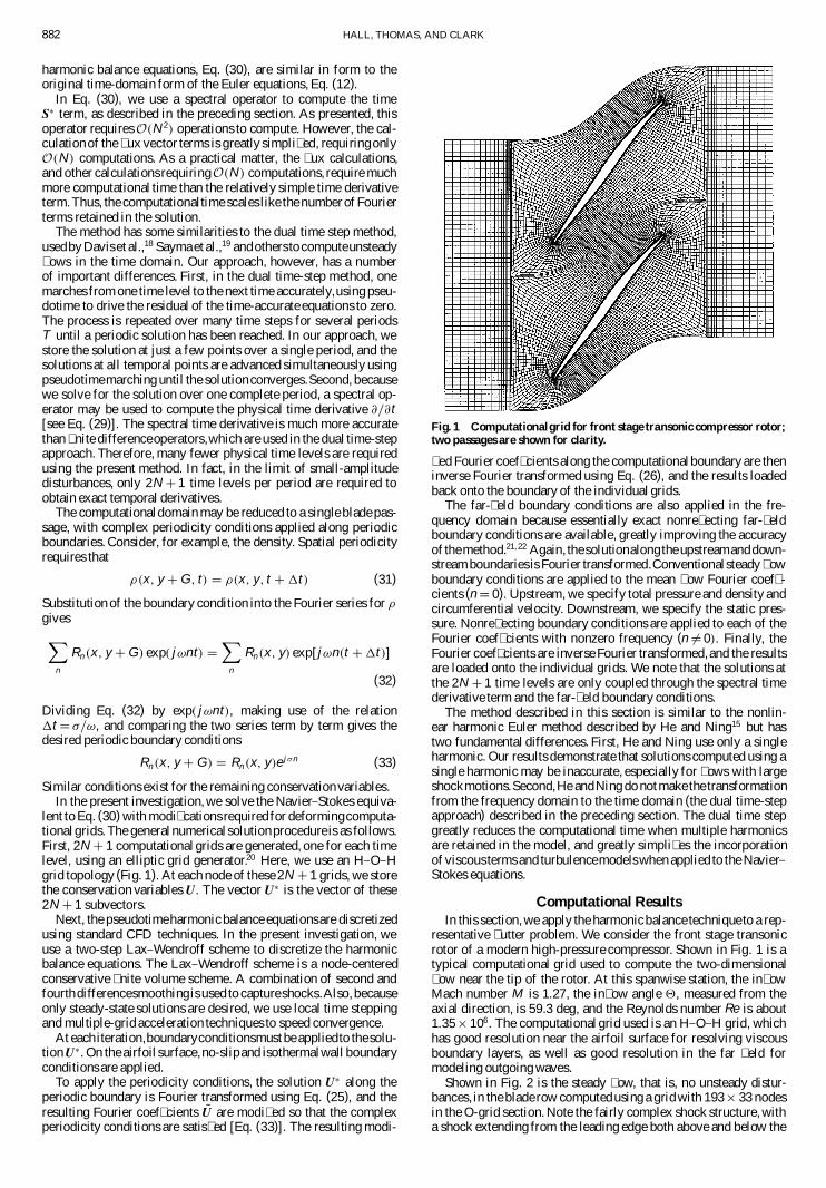


![Unsteady turbulence cascades - imperial.ac.uk · pation law to hold (see [8, 25]). Steady turbulence is an exceptional case of turbulence where the Kolmogorov statistically stationary](https://static.fdocuments.in/doc/165x107/5f8f900e25e3375b833ea9ce/unsteady-turbulence-cascades-pation-law-to-hold-see-8-25-steady-turbulence.jpg)

