comprising “DGT” series Wheel Groups - enatin.com · File: DGT-DGP.07-00 2 IN STEP WITH THE...
17
DRIVE UNIT FOR CRANES comprising “DGT” series Wheel Groups in combination with “DGP” series Offset Geared Motors
Transcript of comprising “DGT” series Wheel Groups - enatin.com · File: DGT-DGP.07-00 2 IN STEP WITH THE...

DRIVE UNIT FOR CRANES
comprising “DGT” series Wheel Groups
in combination with “DGP” series Offset Geared Motors

File: DGT-DGP.07-00 2
IN STEP WITH THE TIMES
Safe, reliable and cost efficient solutions from DONATI SOLLEVAMENTI S.r.l. These drive units for cranes, comprising “DGT” series wheel groups in combination with “DGP” series Offset geared motors are “a modern, safe guide handling system on rails”, and the most convenient offer available for today’s global market, handling up to 25,000 kg on each wheel group. Enhancing its range of DRH series electric wire rope hoists and DMK series chain hoists, trusted by industry professionals worldwide, the drive units for cranes complete the range of products built by DONATI SOLLEVAMENTI S.r.l. a leading Italian and global manufacturer of lifting systems.
DONATI SOLLEVAMENTI S.r.l. Via Roma, 55 - 21020 Daverio (Varese) - Italy - tel. +39 0332 942.611 - fax +39 0332 948.597
E-mail: [email protected] - www.donati-europe.com
DONATI Ltd Unit 40 - Farriers Way Ind. Est. - NETHERTON - LIVERPOOL L30 4XL
tel. +44 (0)151 530 1139 - fax +44 (0)151 525 6613 - E-mail: [email protected]
RIGOROUS QUALITY CONTROL
DONATI SOLLEVAMENTI S.r.l. engineers and designs technically innovative, thoroughly reliable, lifting machinery and components, making use of advanced industrialized production processes which ensure low costs for end-users. Continuous attention to quality allows DONATI SOLLEVAMENTI S.r.l. to consistently manufacture highly engineered, meticulously designed products, using quality control measures on materials throughout the production process, right down to the finished product, involving the company’s entire organization, through its certified quality assurance system in accordance with UNI ISO 9001:2000 norms (Certified ICIM N° 0114), regulating and controlling the company’s management and production organization since 1993.
ISO 9001:2000
Certificate No. 0114
IN HARMONY WITH EUROPE
The rigorous attention placed on all phases of the engineering and design process for all products at DONATI is entirely in line with our diligent consideration for international norms and regulations, a guarantee for our many Customers and end-users, serving as a gateway for the internationalization and diffusion of our products worldwide. The drive units for cranes comprise the “DGT” series wheel groups in combination with “DGP” series Offset geared motors, are designed and manufactured in conformity with legislation in Italy and the following European Community Directives:
• Machinery Directive 98/37/CE (re-codified from Directive 89/392/CEE and subsequent revisions 91/368/CEE, 93/44/CEE and 93/68/CEE).
• Low Voltage Directive 73/23/CEE - 93/68/CEE. • Electromagnetic Compatibility Directive 89/336/CEE - 92/31/CEE

File: DGT-DGP.07-00 3
DRIVE UNITS FOR CRANES
• The drive units for cranes comprise “DGT” series wheel groups in combination with “DGP” series Offset geared
motors, are built specifically for handling lifting systems on rails, such as, for example, travelling cranes, gantry cranes, wall-mounted cranes, etc. and/or related running trolleys, guaranteeing the precise alignment for moving structures, control over high shifting speeds, while facilitating installation and maintenance. The “DGT” series wheel groups and “DGP” series Offset geared motors are available in a wide range of capacities and speeds; they are highly reliable modular components capable of responding flexibly and efficiently to the needs for operating safety, cost efficiency and the rapid setup of drive units for cranes by manufacturers of machinery and industrial lifting and handling installations.
INSTALLATION RESTRICTIONS
• Drive units for cranes are generally designed to be installed on endtrucks, or onto trolleys, travelling cranes, gantry cranes,
etc., travelling loads through horizontal handling operations with the drive units installed on runways’ rails.
PRODUCT DESIGN, RANGE AND PRODUCTION
• These drive units for cranes are designed and engineered based on the principle of modular components which, in addition
to the more common versions commercially available, when assembled to one other in relation to the user’s requirements, allow for the fast and economical realization of multiple standard and special configurations.
• DONATI drive units are configured in 6 sizes, for which the basic components are: • 6 sizes of “DGT” series wheel groups (Ø 125, Ø 160, Ø 200, Ø 250, Ø 315 and Ø 400) • 4 sizes of “DGP” series reducers (DGP 0, DGP 1, DGP 2 and DGP 3) • 4 sizes of self-braking motors (motor 71, motor 80, motor 100 and motor 112)
Composition of drive units based on combinations between “DGT” Wheels and “DGP” Gear Motors
“DGP” swinging gear motors “DGT” wheels Ø ( mm )
“DGP” reducers size 0 “DGP” reducers size 1 “DGP” reducers size 2 “DGP” reducers size 3
125
= =
160
Motors size 71 = =
200
= =
250
=
Motors size 71
Motors size 80
=
315
= =
400
= =
Motors size 80
Motors size 100
Motors size 112
• The 6 production sizes for drive units cover the following operating limitations:
• Capacity of the lifting and/or traversing equipment: from 1000 to 40,000 kg • Running speed: single speed, from 3.2 to 25 m/min; two-speed, from 12.5/3.2 to 80/20 m/min
• The structure’s finishing on the wheel groups and protection from atmospheric and environmental agents (dust, gas, etc.) is guaranteed by the paintwork finish, which features the application of a 40 micron thick base coat of chrome and lead free yellow enamel RAL 1002; surfaces are prepared by grade SA 2 metallic sanding in conformity with SVENSK STANDARD SIS 055900. Oven drying for 40 min. at a temperature of 60-80°C.
• The special waterproof paintwork adopted for the electrical mechanisms (reducer and self-braking motor), obtained through an electrostatic process, and their completely closed execution, guarantee inalterability over time and consistently high performances even in particularly hostile environments.
• The modularity of the basic components (wheels, reducers and motor) allows for the composition of drive units for cranes in two configurations: the drive group and the Idler group.
• The flexibility of the numerous fastening solutions adopted allow for assembly on a variety of mechanical frame types, as well as easy integration with a number of accessories available on the market, such as, for example, guide systems, or collision proof systems, whether mechanical, electrical or electronic, or speed control and crane and trolley stop position systems.
• In addition, DONATI drive units integrate perfectly with limit switches or cycle counters, whether mechanical (worm screw limit switch), electrical (tachometric dynamo), or electronic (encoders), guaranteeing low cost management.
• Safety is a top priority for DONATI SOLLEVAMENTI S.r.l. in its design and manufacturing of all products, aimed at ensuring total reliability during all operative and maintenance phases. For this reason, DONATI drive units are also covered by a 3 year Warranty, from the date of delivery.
File: DGT-DGP.07-00 4
CONFORMITY TO NORMS AND REGULATIONS
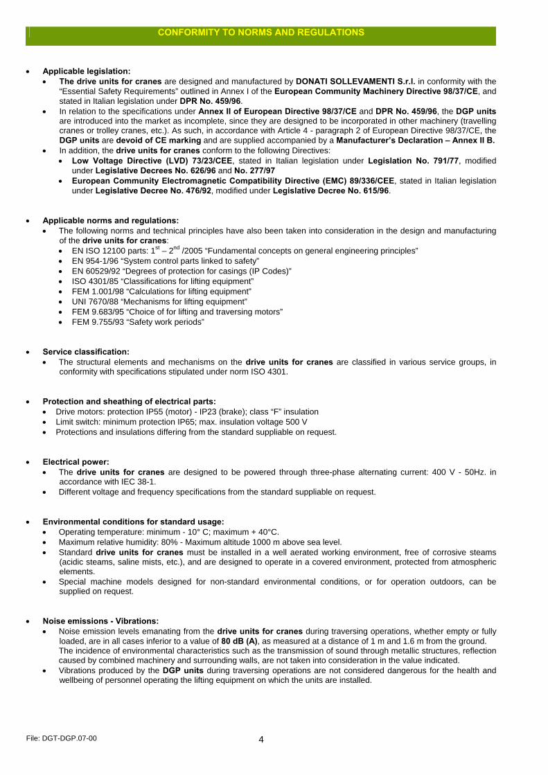
• Applicable legislation:
• The drive units for cranes are designed and manufactured by DONATI SOLLEVAMENTI S.r.l. in conformity with the “Essential Safety Requirements” outlined in Annex I of the European Community Machinery Directive 98/37/CE, and stated in Italian legislation under DPR No. 459/96.
• In relation to the specifications under Annex II of European Directive 98/37/CE and DPR No. 459/96, the DGP units are introduced into the market as incomplete, since they are designed to be incorporated in other machinery (travelling cranes or trolley cranes, etc.). As such, in accordance with Article 4 - paragraph 2 of European Directive 98/37/CE, the DGP units are devoid of CE marking and are supplied accompanied by a Manufacturer’s Declaration – Annex II B.
• In addition, the drive units for cranes conform to the following Directives: • Low Voltage Directive (LVD) 73/23/CEE, stated in Italian legislation under Legislation No. 791/77, modified
under Legislative Decrees No. 626/96 and No. 277/97 • European Community Electromagnetic Compatibility Directive (EMC) 89/336/CEE, stated in Italian legislation
under Legislative Decree No. 476/92, modified under Legislative Decree No. 615/96. • Applicable norms and regulations:
• The following norms and technical principles have also been taken into consideration in the design and manufacturing of the drive units for cranes: • EN ISO 12100 parts: 1st – 2nd /2005 “Fundamental concepts on general engineering principles” • EN 954-1/96 “System control parts linked to safety” • EN 60529/92 “Degrees of protection for casings (IP Codes)” • ISO 4301/85 “Classifications for lifting equipment” • FEM 1.001/98 “Calculations for lifting equipment” • UNI 7670/88 “Mechanisms for lifting equipment” • FEM 9.683/95 “Choice of for lifting and traversing motors” • FEM 9.755/93 “Safety work periods”
• Service classification:
• The structural elements and mechanisms on the drive units for cranes are classified in various service groups, in conformity with specifications stipulated under norm ISO 4301.
• Protection and sheathing of electrical parts:
• Drive motors: protection IP55 (motor) - IP23 (brake); class “F” insulation • Limit switch: minimum protection IP65; max. insulation voltage 500 V • Protections and insulations differing from the standard suppliable on request.
• Electrical power:
• The drive units for cranes are designed to be powered through three-phase alternating current: 400 V - 50Hz. in accordance with IEC 38-1.
• Different voltage and frequency specifications from the standard suppliable on request. • Environmental conditions for standard usage:
• Operating temperature: minimum - 10° C; maximum + 40°C. • Maximum relative humidity: 80% - Maximum altitude 1000 m above sea level. • Standard drive units for cranes must be installed in a well aerated working environment, free of corrosive steams
(acidic steams, saline mists, etc.), and are designed to operate in a covered environment, protected from atmospheric elements.
• Special machine models designed for non-standard environmental conditions, or for operation outdoors, can be supplied on request.
• Noise emissions - Vibrations:
• Noise emission levels emanating from the drive units for cranes during traversing operations, whether empty or fully loaded, are in all cases inferior to a value of 80 dB (A), as measured at a distance of 1 m and 1.6 m from the ground. The incidence of environmental characteristics such as the transmission of sound through metallic structures, reflection caused by combined machinery and surrounding walls, are not taken into consideration in the value indicated.
• Vibrations produced by the DGP units during traversing operations are not considered dangerous for the health and wellbeing of personnel operating the lifting equipment on which the units are installed.
File: DGT-DGP.07-00 5
COMPONENTS ON DRIVE UNITS FOR CRANES
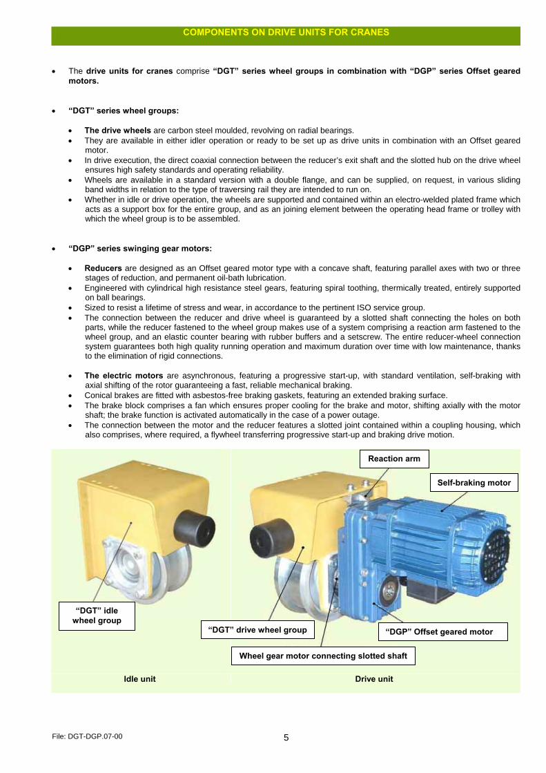
• The drive units for cranes comprise “DGT” series wheel groups in combination with “DGP” series Offset geared
motors. • “DGT” series wheel groups:
• The drive wheels are carbon steel moulded, revolving on radial bearings. • They are available in either idler operation or ready to be set up as drive units in combination with an Offset geared
motor. • In drive execution, the direct coaxial connection between the reducer’s exit shaft and the slotted hub on the drive wheel
ensures high safety standards and operating reliability. • Wheels are available in a standard version with a double flange, and can be supplied, on request, in various sliding
band widths in relation to the type of traversing rail they are intended to run on. • Whether in idle or drive operation, the wheels are supported and contained within an electro-welded plated frame which
acts as a support box for the entire group, and as an joining element between the operating head frame or trolley with which the wheel group is to be assembled.
• “DGP” series swinging gear motors:
• Reducers are designed as an Offset geared motor type with a concave shaft, featuring parallel axes with two or three
stages of reduction, and permanent oil-bath lubrication. • Engineered with cylindrical high resistance steel gears, featuring spiral toothing, thermically treated, entirely supported
on ball bearings. • Sized to resist a lifetime of stress and wear, in accordance to the pertinent ISO service group. • The connection between the reducer and drive wheel is guaranteed by a slotted shaft connecting the holes on both
parts, while the reducer fastened to the wheel group makes use of a system comprising a reaction arm fastened to the wheel group, and an elastic counter bearing with rubber buffers and a setscrew. The entire reducer-wheel connection system guarantees both high quality running operation and maximum duration over time with low maintenance, thanks to the elimination of rigid connections.
• The electric motors are asynchronous, featuring a progressive start-up, with standard ventilation, self-braking with
axial shifting of the rotor guaranteeing a fast, reliable mechanical braking. • Conical brakes are fitted with asbestos-free braking gaskets, featuring an extended braking surface. • The brake block comprises a fan which ensures proper cooling for the brake and motor, shifting axially with the motor
shaft; the brake function is activated automatically in the case of a power outage. • The connection between the motor and the reducer features a slotted joint contained within a coupling housing, which
also comprises, where required, a flywheel transferring progressive start-up and braking drive motion.
Idle unit Drive unit
“DGT” idle wheel group
Reaction arm
Self-braking motor
“DGT” drive wheel group “DGP” Offset geared motor
Wheel gear motor connecting slotted shaft

File: DGT-DGP.07-00 6
TECHNICAL SPECIFICATIONS AND OPERATING LIMITATIONS FOR DGP SERIES DRIVE UNITS FOR CRANES
• For complete technical specifications on the drive units for cranes, in relation to their intended operation, check and match
the parameters limiting their operation. • The tables below provide a suitable means of verifying operating limits for the wheel group in combination with drive reducers
and self-braking motors, in relation to the following user specifications: • operating loads on the wheels • width and shape of the runways rail • running speed • number of wheel groups and motoreducers employed.
Specifications for runways rails and maximum contact area
Square laminated rail UNI 6013 - DIN 1013 Flat laminated rail UNI 6014 - DIN 1017
Burbak type rail - DIN 536
Vignole type rail - UNI 3141
Wheel specifications Rail (mm) Type of running rail and maximum operating contact surface - b ( mm )
Wheel internal width (mm)
width
b (mm)
h
(mm)
Square laminated UNI 6013 - DIN 1013
Flat laminated UNI 6014 - DIN 1017
Burbak - DIN 536
Vignole - UNI 3141
Type Ø
ØR
(mm)
Max Rx
(kN)
type b1 max. min. min. l b = l - 2r type l b = l - 2r type l b = l - 4/3r
standard 50 40 35 30 40 38 = = = = = =
maximum 60 50 45 30 50 48 A 45 45 37 21 - 27 50 34
125
36
special 70 60 55 30 60 58 A 55 55 45 36 60 44
standard 55 45 40 30 40 38 A 45 45 37 = = =
maximum 65 55 50 30 50 48 A 55 55 45 21 - 27 50 34
160
48
special 80 70 65 30 70 68 A 65 65 53 46 50
65 67
46 49
standard 60 50 45 30 50 48 A 45 45 37 21 - 27 50 34
maximum 70 60 55 30 60 58 A 55 55 45 30 36
56 60
40 44
200
72
special 90 80 75 30 80 78 A 75 75 59 60 72 (*) 55
standard 70 60 55 30 60 58 A 55 55 45 30 36
56 60
40 44
maximum 80 70 65 30 70 68 A 65 65 53 46 50
65 67
46 49
250
106
special 100 90 85 30 90 88 A 75 75 (*) 59 = = =
standard 75 65 60 40 60 58 A 65 65 53 36 46
60 65
44 47
maximum 85 75 70 40 70 68 A 75 75 59 50 60
67 (*) 72
48 55
315
144
special 110 100 95 40 100 98 A 100 100 80 = = =
standard 85 75 70 40 70 68 A 75 75 59 50 60
67 (*) 72
48 55
maximum 95 85 80 40 80 78 = = = = = =
400
210
special 110 100 95 40 100 98 A 100 100 80 = = =
• The clearance between the internal width of the wheel and the maximum rail width must be contained within: ≥ 10 mm and ≤ 15 mm • (*) wheel with increased clearance =18 mm • Recommended rails appear in red, together with the operating contact surface values, verified in relation to the maximum static reaction
File: DGT-DGP.07-00 7
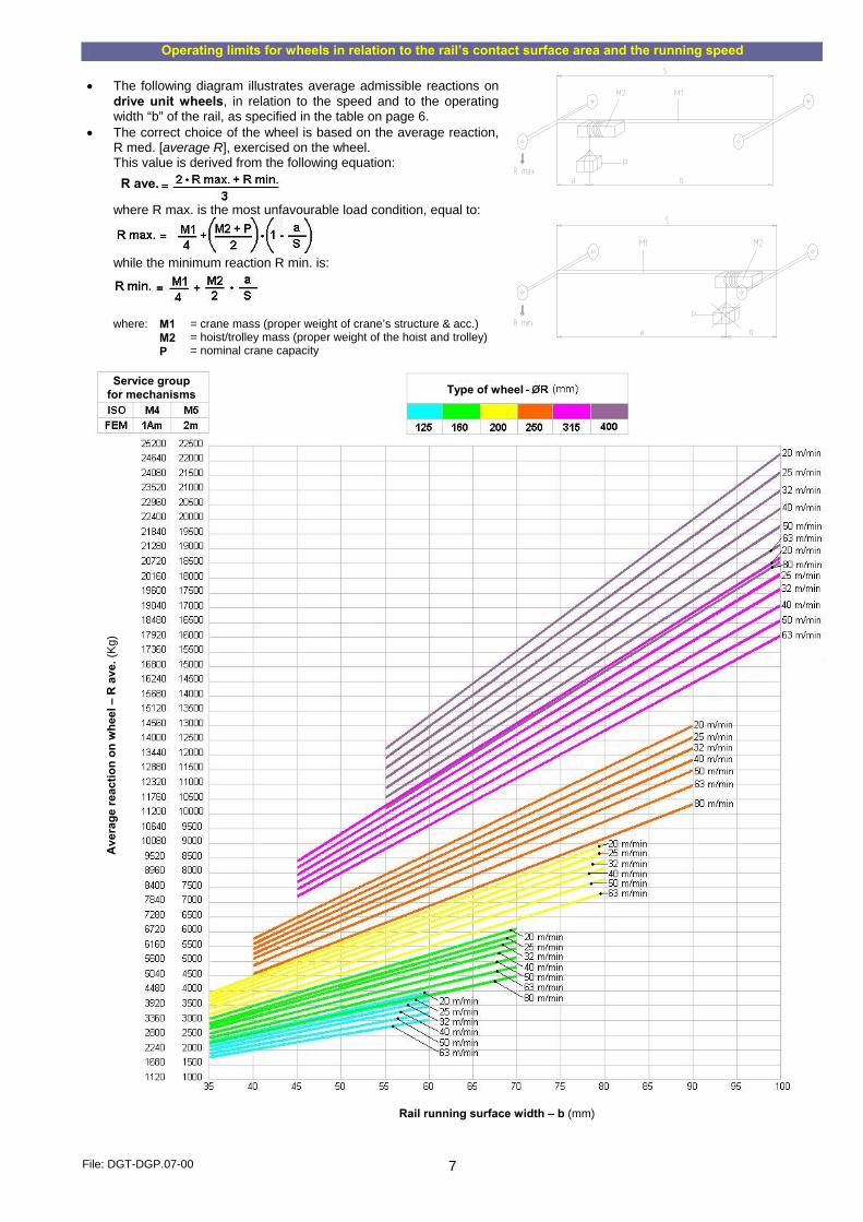
Operating limits for wheels in relation to the rail’s contact surface area and the running speed • The following diagram illustrates average admissible reactions on
drive unit wheels, in relation to the speed and to the operating width “b” of the rail, as specified in the table on page 6.
• The correct choice of the wheel is based on the average reaction, R med. [average R], exercised on the wheel. This value is derived from the following equation:
where R max. is the most unfavourable load condition, equal to:
while the minimum reaction R min. is:
where:
M1 M2 P
= crane mass (proper weight of crane’s structure & acc.) = hoist/trolley mass (proper weight of the hoist and trolley) = nominal crane capacity
R ave.
Service group for mechanisms Type of wheel
Ave
rage
reac
tion
on w
heel
– R
ave
. (K
g)
Rail running surface width – b (mm)
File: DGT-DGP.07-00 8
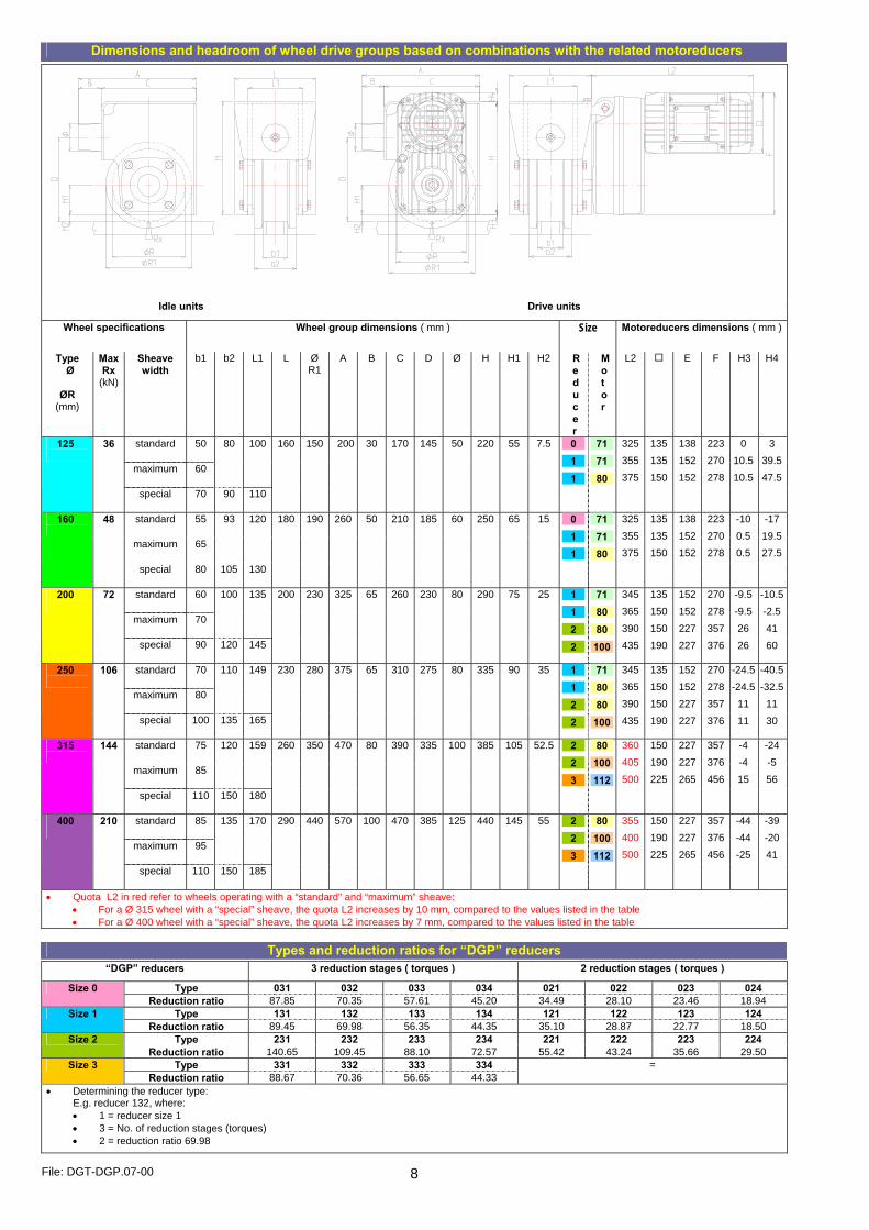
Dimensions and headroom of wheel drive groups based on combinations with the related motoreducers
Idle units Drive units
Wheel specifications Wheel group dimensions ( mm ) Size Motoreducers dimensions ( mm )
Type Ø
ØR
(mm)
Max Rx
(kN)
Sheave width
b1 b2 L1 L Ø R1
A B C D Ø H H1 H2 Reducer
Motor
L2 E F H3 H4
standard 50
maximum 60
80 100125
36
special 70 90 110
160 150 200 30 170 145 50 220 55 7.5 0
1
1
71
71
80
325
355
375
135
135
150
138
152
152
223
270
278
0
10.5
10.5
3
39.5
47.5
standard 55
maximum 65
93 120160
48
special 80 105 130
180 190 260 50 210 185 60 250 65 15 0
1
1
71
71
80
325
355
375
135
135
150
138
152
152
223
270
278
-10
0.5
0.5
-17
19.5
27.5
standard 60
maximum 70
100 135200
72
special 90 120 145
200 230 325 65 260 230 80 290 75 25 1
1
2
2
71
80
80
100
345
365
390
435
135
150
150
190
152
152
227
227
270
278
357
376
-9.5
-9.5
26
26
-10.5
-2.5
41
60
standard 70
maximum 80
110 149250
106
special 100 135 165
230 280 375 65 310 275 80 335 90 35 1
1
2
2
71
80
80
100
345
365
390
435
135
150
150
190
152
152
227
227
270
278
357
376
-24.5
-24.5
11
11
-40.5
-32.5
11
30
standard 75
maximum 85
120 159315
144
special 110 150 180
260 350 470 80 390 335 100 385 105 52.5 2
2
3
80
100
112
360
405
500
150
190
225
227
227
265
357
376
456
-4
-4
15
-24
-5
56
standard 85
maximum 95
135 170400
210
special 110 150 185
290 440 570 100 470 385 125 440 145 55 2
2
3
80
100
112
355
400
500
150
190
225
227
227
265
357
376
456
-44
-44
-25
-39
-20
41
• Quota L2 in red refer to wheels operating with a “standard” and “maximum” sheave: • For a Ø 315 wheel with a “special” sheave, the quota L2 increases by 10 mm, compared to the values listed in the table • For a Ø 400 wheel with a “special” sheave, the quota L2 increases by 7 mm, compared to the values listed in the table
Types and reduction ratios for “DGP” reducers
“DGP” reducers 3 reduction stages ( torques ) 2 reduction stages ( torques )
Type 031 032 033 034 021 022 023 024 Size 0 Reduction ratio 87.85 70.35 57.61 45.20 34.49 28.10 23.46 18.94
Type 131 132 133 134 121 122 123 124 Size 1 Reduction ratio 89.45 69.98 56.35 44.35 35.10 28.87 22.77 18.50
Type 231 232 233 234 221 222 223 224 Size 2 Reduction ratio 140.65 109.45 88.10 72.57 55.42 43.24 35.66 29.50
Type 331 332 333 334 Size 3 Reduction ratio 88.67 70.36 56.65 44.33
=
• Determining the reducer type: E.g. reducer 132, where: • 1 = reducer size 1 • 3 = No. of reduction stages (torques) • 2 = reduction ratio 69.98

File: DGT-DGP.07-00 9
Specifications and codes for self-braking motors combinable with “DGP” reducers
Motor size
Type Poles (no.)
Rpm (rpm)
Power (kW)
Torque (Nm)
Ia (A)
In (A)
cos φ Motor Code
71K8C 8 645 0.08 1.09 1.20 0.90 0.45 M20AP80050 71K4CA 4 1370 0.16 1.09 2.20 0.80 0.55 M20AP40050 71K4CB 4 1370 0.20 1.36 2.70 1.00 0.55 M20AP40051 71K2CA 2 2740 0.32 1.09 3.60 1.00 0.75 M20AP20050 71K2CB 2 2700 0.40 1.36 4.50 1.30 0.70 M20AP20051 71K2L 2 2740 0.50 1.70 5.20 1.30 0.72 M20AP2I050 71K3C 2/8 2760/650 0.32/0.07 1.09 3.60/1.10 1.00/0.80 0.70/0.55 M20AP30050
71
M 20 series
71K3L 2/8 2760/630 0.40/0.09 1.36 4.40/1.20 1.20/0.90 0.75/0.60 M20AP30051 80K8C 8 660 0.12 1.70 2.00 1.20 0.45 M30AP80050 80K8L 8 630 0.16 2.18 2.20 1.30 0.48 M30AP80051
80K4CA 4 1360 0.25 1.70 3.10 0.90 0.65 M30AP40050 80K4CB 4 1370 0.32 2.18 3.90 1.10 0.65 M30AP40051 80K2CA 2 2740 0.50 1.70 5.80 1.30 0.80 M30AP20050 80K2CB 2 2750 0.63 2.18 7.70 1.70 0.75 M30AP20051 80K2L 2 2770 0.80 2.73 9.70 1.90 0.80 M30AP2I050 80K3C 2/8 2740/650 0.50/012 1.70 5.20/1.60 1.30/1.10 0.85/0.60 M30AP30050
80
M 30 series
80K3L 2/8 2760/650 0.63/0.15 2.18 6.70/1.90 1.60/1.30 0.82/0.57 M30AP30051 100K8C 8 680 0.32 4.36 4.60 1.7 0.50 M50AP80050 100K8L 8 670 0.40 5.46 5.40 2.50 0.45 M50AP80051
100K4CA 4 1390 0.63 4.36 8.50 1.70 0.70 M50AP40050 100K4CB 4 1390 0.80 5.46 8.90 2.00 0.80 M50AP40051 100K2CA 2 2820 1.25 4.36 16.50 2.90 0.83 M50AP20050 100K2CB 2 2800 1.60 5.46 21.00 3.70 0.80 M50AP20051 100K2L 2 2780 2.00 6.82 23.00 4.30 0.86 M50AP2I050 100K3C 2/8 2820/680 1.25/0.31 4.36 15.70/3.60 3.10/1.80 0.84/0.60 M50AP30050
100
M 50 series
100K3L 2/8 2790/660 1.60/0.39 5.46 21.00/4.00 3.50/2.30 0.86/0.60 M50AP30051 112K8L 8 690 0.63 8.72 8.60 3.40 0.50 M60AP80050 112K4C 4 1430 1.25 8.72 20.50 3.60 0.65 M60AP40050 112K2L 2 2800 3.20 10.92 39.00 6.50 0.88 M60AP2I050
112
M 60 series
112K3L 2/8 2850/690 2.50/0.62 8.72 33.00/7.30 5.60/3.40 0.85/0.50 M60AP30050 Specifications for self-braking motors are related to the M4 service group ( 1Am ) – duty factor 40% – Power voltage 400 V
Codes for “DGT” drive wheel groups ready for matching with “DGP” reducers
“DGT” drive wheel group Ø (mm) 125 160 200 250 315 400 size 0 DGT1A0M10 DGT2A0M10 = = = =
size 1 DGT1A0M30 DGT2A0M30 DGT3A0M10 DGT4A0M10 = =
size 2 = = DGT3A0M30 DGT4A0M30 DGT5A0M10 (r) DGT5A0M20 (l)
DGT6A0M10 (r) DGT6A0M20 (l)
“DGP” reducers
size 3 = = = = DGT5A0M30 (r) DGT5A0M40 (l)
DGT6A0M30 (r) DGT6A0M40 (l)
• The configuration (r) = right and (l) = left, for wheel groups Ø 315 and Ø 400 refers to the positioning of the welded reaction arm • The codes refer to drive wheels with a standard sheave width. In the case of wheels with different sheave widths, replace the letter M in the code with the
letter P for wheels with a maximum sheave width, or S for wheels with a special sheave width
Max. weights for “DGT” drive wheel groups coupled with “DGP” reducers
“DGT” drive wheel group Ø (mm) 125 160 200 250 315 400
“DGP” reducers size 0
max. 32 ( kg ) max. 40 ( kg ) = = = = “DGP” motors size 71
max. 36 ( kg ) max. 44 ( kg ) max. 54 ( kg ) max. 73 ( kg ) = = “DGP” reducers size 1
max. 38 ( kg ) max. 48 ( kg ) max. 58 ( kg ) max. 75 ( kg ) = = “DGP” motors size 80
= = max. 75 ( kg ) max. 94 ( kg ) max. 125 ( kg ) max. 197 ( kg ) “DGP” reducers size 2
“DGP” motors size 100
= = max. 83 ( kg ) max. 102 ( kg ) max. 133 ( kg ) max. 205 ( kg )
“DGP” swinging gear motor s
“DGP” reducers size 3
“DGP” motors size 112
= = = = max. 172 ( kg ) max. 236 ( kg )
Codes and weights for “DGT” idle wheel groups
“DGT” idel wheel group Ø (mm) 125 160 200 250 315 400
Code DGT1A0M00 DGT2A0M00 DGT3A0M00 DGT4A0M00 DGT5A0M00 DGT6A0M00
Weight ( kg ) 15.5 23.5 37.5 57.0 88.0 152.0
• The codes refer to idle wheels with a standard sheave width. In the case of wheels with different sheave widths, replace the letter M in the code with the letter P for wheels with a maximum sheave width, or S for wheels with a special sheave width

File: DGT-DGP.07-00 10
TRAVELLING MASSES AT 1 SPEED, BASED ON THE MATCHING OF COMPONENTS
Travelling mass ( kg ) Group “DGP” motoreducer Self-braking motor specifications
Codes for components
ISO service group (FEM) “DGT” wheel
Reducer Motor Poles Power Wheel group Motoreducer
Nominal speed
( m/min )
M4 (1Am) M5 (2m) Ø ( mm ) Type Type ( N° ) ( kW ) “DGT” drive “DGP” 7.400 7.400 125 031 71K8C 8 0.08 DGT1A0M10 P0M2B18AA0 3.2 14.700 14.700 200 231 80K8C 8 0.12 DGT3A0M30 P2M3B18AA0 7.400 7.400 125 032 71K8C 8 0.08 DGT1A0M10 P0M2B28AA0 9.800 8.000 160
031 71K8C 8 0.08 DGT2A0M10 P0M2B18AA0
14.700 14.700 200
80K8C 8 0.12 DGT3A0M30
20.800 16.600
232
80K8C 8 0.12
P2M3B28AA0
4
21.600 21.600 250
231 80K8L 8 0.16 DGT4A0M30
P2M3B18KA0 6.700 5.360 033 71K8C 8 0.08 DGT1A0M10 P0M2B38AA0 7.400 7.400
125 133 80K8C 8 0.12 DGT1A0M30 P1M3B38AA0
8.000 6.400 032 71K8C 8 0.08 DGT2A0M10 P0M2B28AA0 9.800 9.800
160 132 80K8C 8 0.12 DGT2A0M30 P1M3B28AA0
9.600 7.600 71K8C 8 0.08 P1M2B18AA0 14.400 11.500 80K8C 8 0.12 P1M3B18AA0 14.700 14.700
200
131
80K8L 8 0.16
DGT3A0M10
P1M3B18KA0 16.800 13.400 80K8C 8 0.12 P2M3B28AA0 21.600 18.000 80K8L 8 0.16 P2M3B28KA0 21.600 21.600
250
232
100K8C 8 0.32
DGT4A0M30
P2M5B28AA0 18.400 14.700 80K8C 8 0.12 P2M3B18AA0 23.300 18.600 80K8L 8 0.16 P2M3B18KA0
5
29.400 29.400
315
231
100K8C 8 0.32
DGT5A0M10 (r) DGT5A0M20 (l)
P2M5B18AA0 7.400 7.400 125
031 71K4CA 4 0.16 DGT1A0M10 P0M2B14AA0
6.400 5.100 033 71K8C 8 0.08 DGT2A0M10 P0M2B38AA0 9.800 8.000
160 133 80K8C 8 0.12 DGT2A0M30 P1M3B18AA0
14.700 14.700 200
231 80K4CA 4 0.25 DGT3A0M30 P2M3B14AA0
9.000 7.200 71K8C 8 0.08 P1M2B18AA0 13.500 10.800 80K8C 8 0.12 P1M3B18AA0 18.000 14.400
131
80K8L 8 0.16
DGT4A0M10
P1M3B18KA0 21.600 21.600
250
233 100K8C 8 0.32 DGT4A0M30 P2M5B38AA0 14.600 11.700 80K8C 8 0.12 P2M3B28AA0 18.600 14.900 80K8L 8 0.16 P2M3B28KA0 29.400 29.400
315
232
100K8C 8 0.32
DGT5A0M10 (r) DGT5A0M20 (l)
P2M5B28AA0 20.800 16.600 80K8L 8 0.16 P2M3B18KA0
6.3
41.400 33.100 400
231
100K8C 8 0.32 DGT6A0M10 (r) DGT6A0M20 (r) P2M5B18AA0
7.400 6.658 125
032 71K4CA 4 0.16 DGT1A0M10 P0M2B24AA0
9.800 8.000 031 71K4CA 4 0.16 DGT2A0M10 P0M2B14AA0 9.800 9.800
160 131 71K4CB 4 0.20 DGT2A0M30 P1M2B14KA0
6.000 4.800 71K8C 8 0.08 P1M2B38AA0 9.400 7.500 80K8C 8 0.12 P1M3B38AA0 12.000 9.600
133
80K8L 8 0.16
DGT3A0M10
P1M3B38KA0 14.700 14.700
200
232 80K4CA 4 0.25 DGT3A0M30 P2M3B24AA0 10.400 8.300 80K8C 8 0.12 P1M3B28AA0 13.800 11.000
132 80K8L 8 0.16
DGT4A0M10 P1M3B28KA0
21.600 17.200 80K4CA 4 0.25 P2M3B14AA0 21.600 21.600
250
231 80K4CB 4 0.32
DGT4A0M30 P2M3B14KA0
14.600 11.700 80K8L 8 0.16 P2M3B38KA0 29.200 23.400 100K8C 8 0.32 P2M5B38AA0 29.400 29.400
315
233
100K8L 8 0.40
DGT5A0M10 (r) DGT5A0M20 (l)
P2M5B38KA0 16.300 13.000 80K8L 8 0.16 P2M3B28KA0 32.600 26.000 100K8C 8 0.32 P2M5B28AA0
8
41.400 33.100
400
232
100K8L 8 0.40
DGT6A0M10 (r) DGT6A0M20 (r)
P2M5B28KA0 6.700 5.360 71K4CA 4 0.16 P0M2B34AA0 7.400 6.720
125
033 71K4CB 4 0.20
DGT1A0M10 P0M2B34KA0
8.000 6.400 71K4CA 4 0.16 P0M2B24AA0 9.800 8.000
032 71K4CB 4 0.20
DGT2A0M10 P0M2B24KA0
9.800 9.800
160
132 80K4CA 4 0.25 DGT2A0M30 P1M3B24AA0 9.600 7.600 71K4CA 4 0.16 P1M2B14AA0 12.000 9.600 71K4CB 4 0.20 P1M2B14KA0 14.700 12.200 80K4CA 4 0.25 P1M3B14AA0 14.700 14.700
200
131
80K4CB 4 0.32
DGT3A0M10
P1M3B14KA0 11.200 8.900 133 80K8L 8 0.16 DGT4A0M10 P1M3B38KA0 17.200 13.700 80K4CA 4 0.25 P2M3B24AA0 21.600 18.000 80K4CB 4 0.32 P2M3B24KA0 21.600 21.600
250 232
100K4CA 4 0.63
DGT4A0M30
P2M5B24AA0 18.500 14.800 80K4CA 4 0.25 P2M3B14AA0 23.300 18.600 80K4CB 4 0.32 P2M3B14KA0 29.400 29.400
315
231
100K4CB 4 0.63
DGT5A0M10 (r) DGT5A0M20 (l)
P2M5B14AA0 26.000 20.800 100K8C 8 0.32 P2M5B38AA0 33.100 26.500
233 100K8L 8 0.40
DGT6A0M10 (r) DGT6A0M20 (r) P2M5B38KA0
10
42.800 41.300
400
331 112K8L 8 0.63 DGT6A0M30 (r) DGT6A0M40 (r)
P3M6B18AA0
• The specifications refer to a single motoreducer; in the case of two or more motoreducers, multiply the travelling mass by the number of motoreducers used.
• Verify that, in relation to the rail’s running surface width (b), the average reaction (R med.) is compatible with the values listed in the diagram at page 7. • The values for travelling mass in red require a verification of average reaction (R med.) on each wheel, which must not exceed the following Rx. max.
values.

File: DGT-DGP.07-00 11
125
R ≤ 36 (kN) 160
R ≤ 48 (kN) 200
R ≤ 72 (kN) 250
R ≤ 106 (kN) 315
R ≤ 144 (kN) 400
R ≤ 210 (kN)

File: DGT-DGP.07-00 12
TRAVELLING MASSES AT 1 SPEED, BASED ON THE MATCHING OF COMPONENTS
Travelling mass ( kg ) Group “DGP” motoreducer Self-braking motor specifications
Codes for components
ISO service group (FEM) “DGT” wheel
Reducer Motor Poles Power Wheel group Motoreducer
Nominal speed
( m/min )
M4 (1Am) M5 (2m) Ø ( mm ) Type Type ( N° ) ( kW ) “DGT” drive “DGP” 7.400 7.400 125 031 71K2CA 2 0.32 DGT1A0M10 P0M2B12AA0 6.400 5.100 71K4CA 4 0.16 P0M2B34AA0 8.000 6.400
033 71K4CB 4 0.20
DGT2A0M10 P0M2B34KA0
9.800 8.000 80K4CA 4 0.25 P1M3B34AA0 9.800 9.800
160
133 80K4CB 4 0.32
DGT2A0M30 P1M3B34KA0
7.600 6.000 71K4CA 4 0.16 P1M2B24AA0 9.600 7.600 71K4CB 4 0.20 P1M2B24KA0 12.000 9.600 80K4CA 4 0.25 P1M3B24AA0 14.700 12.200
132
80K4CB 4 0.32
DGT3A0M10
P1M3B24KA0 14.700 14.700
200
231 80K2CA 2 0.50 DGT3A0M30 P2M3B12AA0 11.200 9.000 71K4CB 4 0.20 P1M2B14KA0 14.000 11.200 80K4CA 4 0.25 P1M3B14AA0 18.000 14.400
131
80K4CB 4 0.32
DGT4A0M10
P1M3B14KA0 21.600 21.600
250
233 100K4CA 4 0.63 DGT4A0M30 P2M5B34AA0 14.800 11.900 80K4CA 4 0.25 P2M3B24AA0 18.600 14.900 80K4CB 4 0.32 P2M3B24KA0 29.400 29.400
315
232
100K4CA 4 0.63
DGT5A0M10 (r) DGT5A0M20 (l)
P2M5B24AA0 20.800 16.600 80K4CB 4 0.32 P2M3B14KA0
12.5
41400 33100 400
231
100K4CA 4 0.63 DGT6A0M10 (r) DGT6A0M20 (r) P2M5B14AA0
7.400 6.656 125 032 71K2CA 2 0.32 DGT1A0M10 P0M2B22AA0 9.800 8.000 031 71K2CA 2 0.32 DGT2A0M10 P0M2B12AA0 9.800 9.800
160 131 71K2CB 2 0.40 DGT2A0M30 P1M2B12KA0
6.000 4.800 71K4CA 4 0.16 P1M2B34AA0 7.500 6.000 71K4CB 4 0.20 P1M2B34KA0 9.400 7.500 80K4CA 4 0.25 P1M3B34AA0 12.000 9.600
133
80K4CB 4 0.32
DGT3A0M10
P1M3B34KA0 14.700 14.700
200
232 80K2CA 2 0.50 DGT3A0M30 P2M3B22AA0 10.800 8.600 80K4CA 4 0.25 P1M3B24AA0 13.800 11.000
132 80K4CB 4 0.32
DGT4A0M10 P1M3B24KA0
21.600 17.200 80K2CA 2 0.50 P2M3B12AA0 21.600 21.600
250
231 80K2CB 2 0.63
DGT4A0M30 P2M3B12KA0
14.600 11.600 80K4CB 4 0.32 P2M3B34KA0 28.900 23.100 100K4CA 4 0.63 P2M5B34AA0 29.400 29.400
315
233
100K4CB 4 0.80
DGT5A0M10 (r) DGT5A0M20 (l)
P2M5B34KA0 16.300 13.000 80K4CB 4 0.32 P2M3B24KA0 32.300 25.800 100K4CA 4 0.63 P2M5B24AA0
16
41.400 33.100
400
232
100K4CB 4 0.80
DGT6A0M10 (r) DGT6A0M20 (r)
P2M5B24KA0 6.720 5.376 71K2CA 2 0.32 P0M2B32AA0 7.400 6.720
125 033 71K2CB 2 0.40
DGT1A0M10 P0M2B32KA0
8.000 6.400 71K2CA 2 0.32 P0M2B22AA0 9.800 8.000
032 71K2CB 2 0.40
DGT2A0M10 P0M2B22KA0
9.800 9.800
160
132 71K2L 2 with inverter 0.50 DGT2A0M30 P1M2B2IKA0 9.600 7.600 71K2CA 2 0.32 P1M2B12AA0 12.000 9.600 71K2CB 2 0.40 P1M2B12KA0 14.700 12.200 71K2L 2 0.50 P1M2B1IKA0 14.700 14.700
200
131
80K2CB 2 0.63
DGT3A0M10
P1M3B12KA0 11.200 8.900 133 80K4CB 4 0.32 DGT4A0M10 P1M3B34KA0 17.200 13.700 80K2CA 2 0.50 P2M3B22AA0 21.600 17.200 80K2CB 2 0.63 P2M3B22KA0 21.600 21.600
250 232
80K2L 2 with inverter 0.80
DGT4A0M30
P2M3B2IKA0 18.500 14.800 80K2CA 2 0.50 P2M3B12AA0 23.300 18.600 80K2CB 2 0.63 P2M3B12KA0 29.400 23.700 80K2L 2 0.80 P2M3B1IKA0 29.400 29.400
315
231
100K2CA 2 1.25
DGT5A0M10 (r) DGT5A0M20 (l)
P2M5B12AA0 25.800 20.600 100K4CA 4 0.63 P2M5B34AA0 33.100 26.500
233 100K4CB 4 0.80
DGT6A0M10 (r) DGT6A0M20 (r) P2M5B34KA0
20
42.800 41.300
400
331 112K4C 4 1.25 DGT6A0M30 (r) DGT6A0M40 (r)
P3M6B14AA0
6.400 5.100 71K2CA 2 0.32 P0M2B32AA0 8.000 6.400 71K2CB 2 0.40 P0M2B32KA0 9.800 8.000
033
71K2L 2 with inverter 0.50
DGT2A0M10
P0M2B3IKA0 9.800 9.800
160
133 80K2CB 2 0.63 DGT2A0M30 P1M3B32KA0 9.000 7.200 71K2CA 2 0.32 P1M2B12AA0 11.200 8.900 71K2CB 2 0.40 P1M2B12KA0 13.800 11.000 71K2L 2 with inverter 0.50 P1M2B1IKA0 17.200 13.800
131
80K2CB 2 0.63
DGT4A0M10
P1M3B12KA0 21.600 17.200 100K2CA 2 1.25 P2M5B32AA0 21.600 21.600
250
233 100K2CB 2 1.60
DGT4A0M30 P2M5B32KA0
16.500 13.200 80K2CA 2 0.50 P2M3B12AA0 20.800 16.600 80K2CB 2 0.63 P2M3B12KA0 26.500 21.200 80K2L 2 with inverter 0.80 P2M3B1IKA0
25
41.400 33.100
400
231
100K2CA 2 1.25
DGT6A0M10 DGT6A0M20
P2M5B12AA0 • The specifications refer to a single motoreducer; in the case of two or more motoreducers, multiply the travelling mass by the number of motoreducers used.• Verify that, in relation to the rail’s running surface width (b), the average reaction (R med.) is compatible with the values listed in the diagram at page 7. • The values for travelling mass in red require a verification of average reaction (R med.) on each wheel, which must not exceed the following Rx. max.
values. 125
R ≤ 36 (kN) 160
R ≤ 48 (kN) 200
R ≤ 72 (kN) 250
R ≤ 106 (kN) 315
R ≤ 144 (kN) 400
R ≤ 210 (kN)
File: DGT-DGP.07-00 13
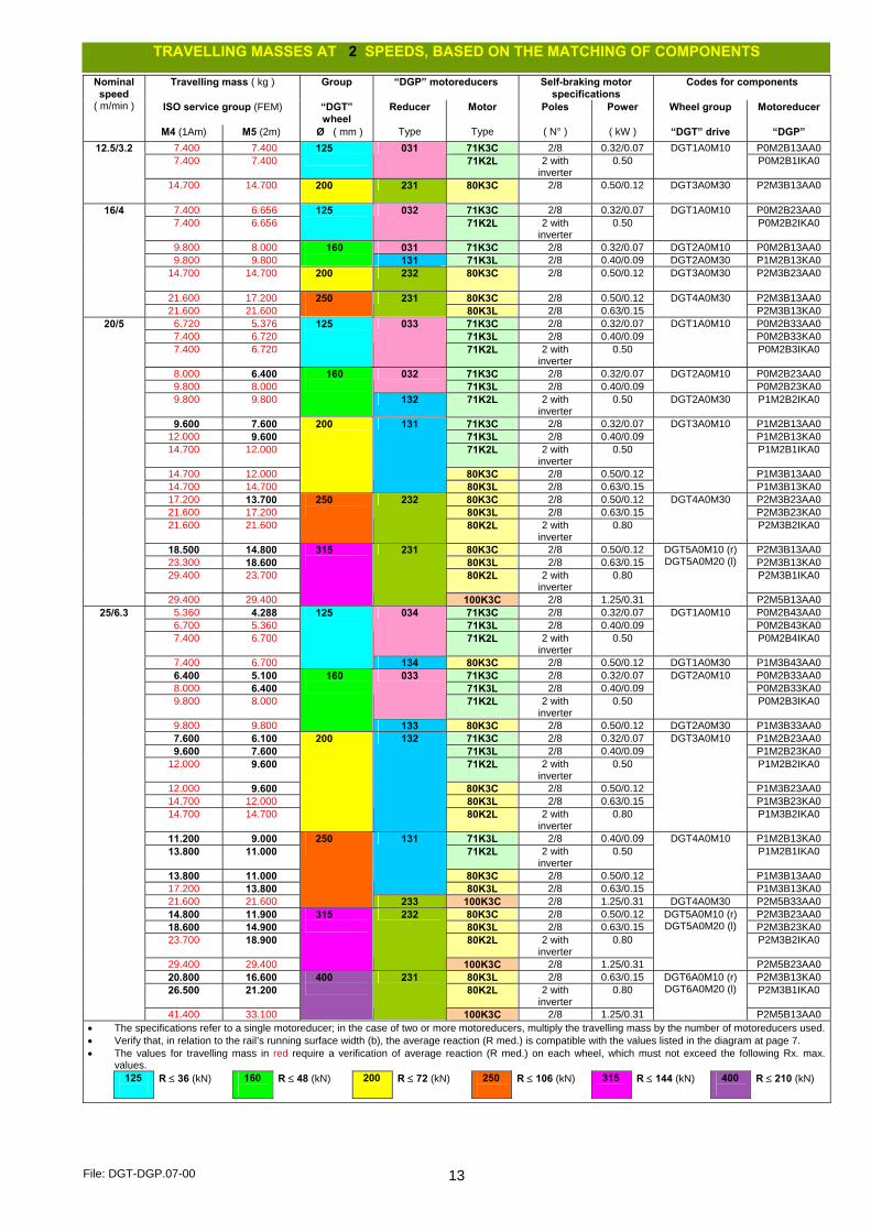
TRAVELLING MASSES AT 2 SPEEDS, BASED ON THE MATCHING OF COMPONENTS
Travelling mass ( kg ) Group “DGP” motoreducers Self-braking motor specifications
Codes for components
ISO service group (FEM) “DGT” wheel
Reducer Motor Poles Power Wheel group Motoreducer
Nominal speed
( m/min )
M4 (1Am) M5 (2m) Ø ( mm ) Type Type ( N° ) ( kW ) “DGT” drive “DGP” 7.400 7.400 71K3C 2/8 0.32/0.07 P0M2B13AA0 7.400 7.400
125
031 71K2L 2 with
inverter 0.50
DGT1A0M10 P0M2B1IKA0
12.5/3.2
14.700 14.700 200
231 80K3C 2/8 0.50/0.12 DGT3A0M30 P2M3B13AA0
7.400 6.656 71K3C 2/8 0.32/0.07 P0M2B23AA0 7.400 6.656
125
032 71K2L 2 with
inverter 0.50
DGT1A0M10 P0M2B2IKA0
9.800 8.000 031 71K3C 2/8 0.32/0.07 DGT2A0M10 P0M2B13AA0 9.800 9.800
160 131 71K3L 2/8 0.40/0.09 DGT2A0M30 P1M2B13KA0
14.700 14.700 200
232 80K3C 2/8 0.50/0.12 DGT3A0M30 P2M3B23AA0
21.600 17.200 80K3C 2/8 0.50/0.12 P2M3B13AA0
16/4
21.600 21.600 250
231
80K3L 2/8 0.63/0.15 DGT4A0M30
P2M3B13KA0 6.720 5.376 71K3C 2/8 0.32/0.07 P0M2B33AA0 7.400 6.720 71K3L 2/8 0.40/0.09 P0M2B33KA0 7.400 6.720
125
033
71K2L 2 with inverter
0.50
DGT1A0M10
P0M2B3IKA0
8.000 6.400 71K3C 2/8 0.32/0.07 P0M2B23AA0 9.800 8.000
032 71K3L 2/8 0.40/0.09
DGT2A0M10 P0M2B23KA0
9.800 9.800
160
132 71K2L 2 with inverter
0.50 DGT2A0M30 P1M2B2IKA0
9.600 7.600 71K3C 2/8 0.32/0.07 P1M2B13AA0 12.000 9.600 71K3L 2/8 0.40/0.09 P1M2B13KA0 14.700 12.000 71K2L 2 with
inverter 0.50 P1M2B1IKA0
14.700 12.000 80K3C 2/8 0.50/0.12 P1M3B13AA0 14.700 14.700
200
131
80K3L 2/8 0.63/0.15
DGT3A0M10
P1M3B13KA0 17.200 13.700 80K3C 2/8 0.50/0.12 P2M3B23AA0 21.600 17.200 80K3L 2/8 0.63/0.15 P2M3B23KA0 21.600 21.600
250
232
80K2L 2 with inverter
0.80
DGT4A0M30
P2M3B2IKA0
18.500 14.800 80K3C 2/8 0.50/0.12 P2M3B13AA0 23.300 18.600 80K3L 2/8 0.63/0.15 P2M3B13KA0 29.400 23.700 80K2L 2 with
inverter 0.80 P2M3B1IKA0
20/5
29.400 29.400
315
231
100K3C 2/8 1.25/0.31
DGT5A0M10 (r) DGT5A0M20 (l)
P2M5B13AA0 5.360 4.288 71K3C 2/8 0.32/0.07 P0M2B43AA0 6.700 5.360 71K3L 2/8 0.40/0.09 P0M2B43KA0 7.400 6.700
034
71K2L 2 with inverter
0.50
DGT1A0M10
P0M2B4IKA0
7.400 6.700
125
134 80K3C 2/8 0.50/0.12 DGT1A0M30 P1M3B43AA0 6.400 5.100 71K3C 2/8 0.32/0.07 P0M2B33AA0 8.000 6.400 71K3L 2/8 0.40/0.09 P0M2B33KA0 9.800 8.000
033
71K2L 2 with inverter
0.50
DGT2A0M10
P0M2B3IKA0
9.800 9.800
160
133 80K3C 2/8 0.50/0.12 DGT2A0M30 P1M3B33AA0 7.600 6.100 71K3C 2/8 0.32/0.07 P1M2B23AA0 9.600 7.600 71K3L 2/8 0.40/0.09 P1M2B23KA0 12.000 9.600 71K2L 2 with
inverter 0.50 P1M2B2IKA0
12.000 9.600 80K3C 2/8 0.50/0.12 P1M3B23AA0 14.700 12.000 80K3L 2/8 0.63/0.15 P1M3B23KA0 14.700 14.700
200
132
80K2L 2 with inverter
0.80
DGT3A0M10
P1M3B2IKA0
11.200 9.000 71K3L 2/8 0.40/0.09 P1M2B13KA0 13.800 11.000 71K2L 2 with
inverter 0.50 P1M2B1IKA0
13.800 11.000 80K3C 2/8 0.50/0.12 P1M3B13AA0 17.200 13.800
131
80K3L 2/8 0.63/0.15
DGT4A0M10
P1M3B13KA0 21.600 21.600
250
233 100K3C 2/8 1.25/0.31 DGT4A0M30 P2M5B33AA0 14.800 11.900 80K3C 2/8 0.50/0.12 P2M3B23AA0 18.600 14.900 80K3L 2/8 0.63/0.15 P2M3B23KA0 23.700 18.900 80K2L 2 with
inverter 0.80 P2M3B2IKA0
29.400 29.400
315
232
100K3C 2/8 1.25/0.31
DGT5A0M10 (r) DGT5A0M20 (l)
P2M5B23AA0 20.800 16.600 80K3L 2/8 0.63/0.15 P2M3B13KA0 26.500 21.200 80K2L 2 with
inverter 0.80 P2M3B1IKA0
25/6.3
41.400 33.100
400
231
100K3C 2/8 1.25/0.31
DGT6A0M10 (r) DGT6A0M20 (l)
P2M5B13AA0 • The specifications refer to a single motoreducer; in the case of two or more motoreducers, multiply the travelling mass by the number of motoreducers used.• Verify that, in relation to the rail’s running surface width (b), the average reaction (R med.) is compatible with the values listed in the diagram at page 7. • The values for travelling mass in red require a verification of average reaction (R med.) on each wheel, which must not exceed the following Rx. max.
values. 125
R ≤ 36 (kN) 160
R ≤ 48 (kN) 200
R ≤ 72 (kN) 250
R ≤ 106 (kN) 315
R ≤ 144 (kN) 400
R ≤ 210 (kN)

File: DGT-DGP.07-00 14
TRAVELLING MASSES AT 2 SPEEDS, BASED ON THE MATCHING OF COMPONENTS
Travelling mass ( kg ) Group “DGP” gear motor Self-braking motor specifications
Codes for components
ISO service group (FEM) “DGT” wheel
Reducer Motor Poles Power Wheel group Gear motor
Nominal speed
( m/min )
M4 (1Am) M5 (2m) Ø ( mm ) Type Type ( N° ) ( kW ) “DGT” drive “DGP” 4.160 3.328 71K3C 2/8 0.32/0.07 P0M2A13AA0 5.200 4.160
021 71K3L 2/8 0.40/0.09
DGT1A0M10 P0M2A13KA0
6.500 5.200 71K2L 2 with inverter 0.50 P1M2A1IKA0 6.500 5.200 80K3C 2/8 0.50/0.12 P1M3A13AA0 7.400 6.656 80K3L 2/8 0.63/0.15 P1M3A13KA0 7.400 6.656
125
121
80K2L 2 with inverter 0.80
DGT1A0M30
P1M3A1IKA0 5.000 4.000 71K3C 2/8 0.32/0.07 P0M2B43AA0 6.300 5.000 71K3L 2/8 0.40/0.09 P0M2B43KA0 7.900 6.300
034
71K2L 2 with inverter 0.50
DGT2A0M10
P0M2B4IKA0 7.900 6.300 80K3C 2/8 0.50/0.12 P1M3B43AA0 9.800 8.000 80K3L 2/8 0.63/0.15 P1M3B43KA0 9.800 9.800
160
134
80K2L 2 with inverter 0.80
DGT2A0M30
P1M3B4IKA0 7.600 6.000 71K3L 2/8 0.40/0.09 P1M2B33KA0 9.600 7.600 71K2L 2 with inverter 0.50 P1M2B3IKA0 9.600 7.600 80K3C 2/8 0.50/0.12 P1M3B33AA0 12.000 9.600 80K3L 2/8 0.63/0.15 P1M3B33KA0 14.700 12.000
133
80K2L 2 with inverter 0.80
DGT3A0M10
P1M3B3IKA0 14.700 14.700
200
221 100K3C 2/8 1.25/0.31 DGT3A0M30 P2M5A13AA0 10.800 8.600 71K2L 2 with inverter 0.50 P1M2B2IKA0 10.800 8.600 80K3C 2/8 0.50/0.12 P1M3B23AA0 13.500 10.800 80K3L 2/8 0.63/0.15 P1M3B23KA0 17.200 13.700
132
80K2L 2 with inverter 0.80
DGT4A0M10
P1M3B2IKA0 21.600 21.600
250
234 100K3C 2/8 1.25/0.31 DGT4A0M30 P2M5B43AA0 14.600 11.600 80K3L 2/8 0.63/0.15 P2M3B33KA0 18.500 14.800 80K2L 2 with inverter 0.80 P2M3B3IKA0 28.900 23.100 100K3C 2/8 1.25/0.31 P2M5B33AA0 29.400 29.400
315
233
100K3L 2/8 1.60/0.39
DGT5A0M10 (r) DGT5A0M20 (l)
P2M5B33KA0 20.700 16.500 80K2L 2 with inverter 0.80 P2M3B2IKA0 32.300 25.800 100K3C 2/8 1.25/0.31 P2M5B23AA0
32/8
41.400 33.100
400
232
100K3L 2/8 1.60/0.39
DGT6A0M10 (r) DGT6A0M20 (l)
P2M5B23KA0 3.360 2.688 71K3C 2/8 0.32/0.07 P0M2A23AA0 4.200 3.360 71K3L 2/8 0.40/0.09 P0M2A23KA0 5.250 4.200
022
71K2L 2 with inverter 0.50
DGT1A0M10
P0M2A2IKA0 5.250 4.200 80K3C 2/8 0.50/0.12 P1M3A23AA0 6.695 5.356 80K3L 2/8 0.63/0.15 P1M3A23KA0 7.400 6.720
125
122
80K2L 2 with inverter 0.80
DGT1A0M30
P1M3A2IKA0 5.000 4.000 021 71K3L 2/8 0.40/0.09 DGT2A0M10 P0M2A13KA0 6.300 5.000 71K2L 2 with
inverter 0.50 P1M2A1IKA0
6.300 5.000 80K3C 2/8 0.50/0.12 P1M3A13AA0 7.900 6.300 80K3L 2/8 0.63/0.15 P1M3A13KA0 10.000 8.000
160 121
80K2L 2 with inverter
0.80
DGT2A0M30
P1M3A1IKA0
7.600 6.000 71K2L 2 with inverter
0.50 P1M2B4IKA0
7.600 6.000 80K3C 2/8 0.50/0.12 P1M3B43AA0 9.400 7.600 80K3L 2/8 0.63/0.15 P1M3B43KA0 12.000 9.600
134
80K2L 2 with inverter
0.80
DGT3A0M10
P1M3B4IKA0
14.700 14.700
200
222 100K3C 2/8 1.25/0.31 DGT3A0M30 P2M5A23AA0 10.800 8.600 80K3L 2/8 0.63/0.15 P1M3B33KA0 13.500 10.800
133 80K2L 2 with
inverter 0.80
DGT4A0M10 P1M3B3IKA0
21.600 17.200 100K3C 2/8 1.25/0.31 P2M5A13AA0 21.600 21.600
250
221 100K3L 2/8 1.60/0.39
DGT4A0M30 P2M5A13KA0
11.600 9.300 80K3L 2/8 0.63/0.15 P2M3B43KA0 14.800 11.900 80K2L 2 with
inverter 0.80 P2M3B4IKA0
23.000 18.400 100K3C 2/8 1.25/0.31 P2M5B43AA0 29.400 23.700 100K3L 2/8 1.60/0.39 P2M5B43KA0 29.400 29.400
315
234
100K2L 2 with inverter
2.00
DGT5A0M10 (r) DGT5A0M20 (l)
P2M5B4IKA0
13.000 10.400 80K3L 2/8 0.63/0.15 P2M3B33KA0 16.500 13.200 80K2L 2 with
inverter 0.80 P2M3B3IKA0
25.800 20.600 100K3C 2/8 1.25/0.31 P2M5B33AA0 33.100 26.400 100K3L 2/8 1.60/0.39 P2M5B33KA0 41.300 33.100
233
100K2L 2 with inverter
2.00
DGT6A0M10 (r) DGT6A0M20 (l)
P2M5B3IKA0
40/10
42.800 41.300
400
331 112K3L 2/8 2.50/0.62 DGT6A0M30 (r) DGT6A0M40 (l)
P3M6B13KA0
• The specifications refer to a single motoreducer; in the case of two or more motoreducers, multiply the travelling mass by the number of motoreducers used.• Verify that, in relation to the rail’s running surface width (b), the average reaction (R med.) is compatible with the values listed in the diagram at page 7. • The values for travelling mass in red require a verification of average reaction (R med.) on each wheel, which must not exceed the following Rx. max.
values. 125
R ≤ 36 (kN) 160
R ≤ 48 (kN) 200
R ≤ 72 (kN) 250
R ≤ 106 (kN) 315
R ≤ 144 (kN) 400
R ≤ 210 (kN)
File: DGT-DGP.07-00 15
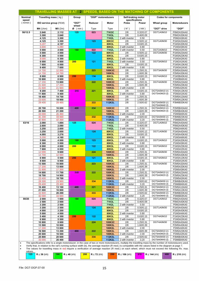
TRAVELLING MASSES AT 2 SPEEDS, BASED ON THE MATCHING OF COMPONENTS
Travelling mass ( kg ) Group “DGP” motoreducers Self-braking motor specifications
Codes for components
ISO service group (FEM) “DGT” wheel
Reducer Motor Poles Power Wheel group Motoreducers
Nominal speed
( m/min )
M4 (1Am) M5 (2m) Ø ( mm ) Type Type ( N° ) ( kW ) “DGT” drive “DGP” 2.640 2.112 71K3C 2/8 0.32/0.07 P0M2A33AA0 3.300 2.640 71K3L 2/8 0.40/0.09 P0M2A33KA0 4.125 3.300
023
71K2L 2 with inverter 0.50
DGT1A0M10
P0M2A3IKA0 4.125 3.300 80K3C 2/8 0.50/0.12 P1M3A33AA0 5.197 4.157 80K3L 2/8 0.63/0.15 P1M3A33KA0 6.600 5.280
125
123
80K2L 2 with inverter 0.80
DGT1A0M30
P1M3A3IKA0 5 000 4 000 022 71K2L 2 with inverter 0.50 DGT2A0M10 P0M2A2IKA0 5 000 4 000 80K3C 2/8 0.50/0.12 P1M3A23AA0 6 300 5 000 80K3L 2/8 0.63/0.15 P1M3A23KA0 8 000 6 300
160 122
80K2L 2 with inverter 0.80
DGT2A0M30
P1M3A2IKA0 6 000 4 800 71K2L 2 with inverter 0.50 P1M2A1IKA0 7 600 6 000 80K3L 2/8 0.63/0.15 P1M3A13KA0 9 400 7 600
121
80K2L 2 with inverter 0.80
DGT3A0M10
P1M3A1IKA0 14 700 12 000 100K3C 2/8 1.25/0.31 P2M5A33AA0 14 700 14 700
200
223 100K3L 2/8 1.60/0.39
DGT3A0M30 P2M5A33KA0
8 600 6 900 80K3L 2/8 0.63/0.15 P1M3B43KA0 10 800 8 600
134 80K2L 2 with inverter 0.80
DGT4A0M10 P1M3B4IKA0
17 200 13 800 100K3C 2/8 1.25/0.31 P2M5A23AA0 21 600 17 200 100K3L 2/8 1.60/0.39 P2M5A23KA0 21 600 21 600
250
222
100K2L 2 with inverter 2.00
DGT4A0M30
P2M5A2IKA0 9 200 7 400 80K3L 2/8 0.63/0.15 P2M3A13KA0 11 800 9 400 80K2L 2 with inverter 0.80 P2M3A1IKA0 18 400 14 700 100K3C 2/8 1.25/0.31 P2M5A13AA0 23 600 18 900
221
100K3L 2/8 1.60/0.39
DGT5A0M10 (r) DGT5A0M20 (l)
P2M5A13KA0 29 400 29 400
315
333 112K3L 2/8 2.50/0.62 DGT5A0M30 (r) DGT5A0M40 (l)
P3M6B33KA0
20 700 16 600 100K3C 2/8 1.25/0.31 P2M5B43AA0 26 500 21 200 100K3L 2/8 1.60/0.39 P2M5B43KA0 33 000 26 400
234
100K2L 2 with inverter 2.00
DGT6A0M10 (r) DGT6A0M20 (l)
P2M5B4IKA0 41 200 33 000 112K3L 2/8 2.50/0.62 P3M6B23KA0
50/12.5
42 800 42 200
400
332 112K2L 2 with inverter 3.20
DGT6A0M30 (r) DGT6A0M40 (l) P3M6B2IKA0
2.080 1.664 71K3C 2/8 0.32/0.07 P0M2A43AA0 2.600 2.080 71K3L 2/8 0.40/0.09 P0M2A43KA0 3.250 2.600
024
71K2L 2 with inverter 0.50
DGT1A0M10
P0M2A4IKA0 3.250 2.600 80K3C 2/8 0.50/0.12 P1M3A43AA0 4.095 3.276 80K3L 2/8 0.63/0.15 P1M3A43KA0 5.200 4.160
125
124
80K2L 2 with inverter 0.80
DGT1A0M30
P1M3A4IKA0 5 000 4 000 80K3L 2/8 0.63/0.15 P1M3A33KA0 6 300 5 000
160
123 80K2L 2 with inverter 0.80
DGT2A0M10 P1M3A3IKA0
6 000 4 800 80K3L 2/8 0.63/0.15 P1M3A23KA0 7 600 6 000
122 80K2L 2 with inverter 0.80
DGT3A0M10 P1M3A2IKA0
12 000 9 600 100K3C 2/8 1.25/0.31 P2M5A43AA0 14 700 12 000
200
224 100K3L 2/8 1.60/0.39
DGT3A0M30 P2M5A43KA0
6 900 5 500 80K3L 2/8 0.63/0.15 P1M3A13KA0 8 600 6 900
121 80K2L 2 with inverter 0.80
DGT4A0M10 P1M3A1IKA0
13 500 10 800 100K3C 2/8 1.25/0.31 P2M5A33AA0 17 200 13 800 100K3L 2/8 1.60/0.39 P2M5A33KA0 21 600 17 200
250
223
100K2L 2 with inverter 2.00
DGT4A0M30
P2M5A3IKA0 14 600 11 700 100K3C 2/8 1.25/0.31 P2M5A23AA0 18 700 14 900 100K3L 2/8 1.60/0.39 P2M5A23KA0 23 400 18 700
222
100K2L 2 with inverter 2.00
DGT5A0M10 (r) DGT5A0M20 (l)
P2M5A2IKA0 29 300 23 500 112K3L 2/8 2.50/0.62 P3M6B43KA0 29 400 29 400
315
334 112K2L 2 with inverter 3.20
DGT5A0M30 (r) DGT5A0M40 (l) P3M6B4IKA0
16 400 13 100 100K3C 2/8 1.25/0.31 P2M5A13AA0 21 000 16 800
221 100K3L 2/8 1.60/0.39
DGT6A0M10 (r) DGT6A0M20 (l) P2M5A13KA0
32 800 26 200 112K3L 2/8 2.50/0.62 P3M6B33KA0
63/16
42 000 33 600
400
333 112K2L 2 with inverter 3.20
DGT6A0M30 (r) DGT6A0M40 (l) P3M6B3IKA0
2 000 1 600 71K3C 2/8 0.32/0.07 P0M2A43AA0 2 500 2 000 71K3L 2/8 0.40/0.09 P0M2A43KA0 3 200 2 500
024
71K2L 2 with inverter 0.50
DGT1A0M10
P0M2A4IKA0 3 200 2 500 80K3C 2/8 0.50/0.12 P1M3A43AA0 4 000 3 200 80K3L 2/8 0.63/0.15 P1M3A43KA0 5 000 4 000
160
124
80K2L 2 with inverter 0.80
DGT1A0M30
P1M3A4IKA0 5 400 4 300 80K3L 2/8 0.63/0.15 P1M3A23KA0 6 900 5 500
122 80K2L 2 with inverter 0.80
DGT4A0M10 P1M3A2IKA0
10 800 8 600 100K3C 2/8 1.25/0.31 P2M5A43AA0 13 500 10 800 100K3L 2/8 1.60/0.39 P2M5A43KA0 17 200 13 800
250
224
100K2L 2 with inverter 2.00
DGT4A0M30
P2M5A4IKA0 16 500 13 200 100K3L 2/8 1.60/0.39 P2M5A23KA0 20 600 16 500
222 100K2L 2 with inverter 2.00
DGT6A0M10 (r) DGT6A0M20 (l) P2M5A2IKA0
25 800 20 600 112K3L 2/8 2.50/0.62 P3M6B43KA0
80/20
33 000 26 400
400
334 112K2L 2 with inverter 3.20
DGT6A0M30 (r) DGT6A0M40 (l) P3M6B4IKA0
• The specifications refer to a single motoreducer; in the case of two or more motoreducers, multiply the travelling mass by the number of motoreducers used.• Verify that, in relation to the rail’s running surface width (b), the average reaction (R med.) is compatible with the values listed in the diagram at page 7. • The values for travelling mass in red require a verification of average reaction (R med.) on each wheel, which must not exceed the following Rx. max.
values. 125
R ≤ 36 (kN) 160
R ≤ 48 (kN) 200
R ≤ 72 (kN) 250
R ≤ 106 (kN) 315
R ≤ 144 (kN) 400
R ≤ 210 (kN)

File: DGT-DGP.07-00 16
SAMPLE GUIDELINES FOR SELECTING DRIVE UNITS FOR CRANES To make the correct choice of drive unit, firstly establish all operating parameters which determine its operating limitations, defining and/or verifying the following factors (see sample guidelines for various “limit” cases listed below, purely by way of example):
1. Define operating data: nominal load, running speed (1 or 2 speed) and ISO service group (FEM); 2. Define: the mass (weight) of the crane or trolley in question and any accessories (frame, electrical system, etc.); 3. Define: in the case of a crane, the weight of the hoist/trolley or trolley/winch, or any movable masses (blocks, etc.) in the case of trolleys; 4. Calculate: the total mass to be traversed, i.e. the nominal load + all equipment masses (weight of crane, trolley, etc.); 5. Define: the no. of motor drive units, necessaries for the running of the total mass to be travelled; 6. Calculate: the mass each drive wheel must travel (i.e. the ratio between the total mass and the no. of wheel drive groups); 7. Verify: the maximum, minimum and average reactions on the wheels, considering the load approach/eccentricities; 8. Verify: the congruency of the rail running surface width, in relation to the type of rail on which the wheels will run on.
1st Example: Single girder crane - Capacity 5 t - Span 16 m 1. nominal load P = 5000 kg; 2 crane running speeds = 40/10 m/min; ISO service group M4 (FEM 1Am) 2. weight of crane + accessories : M1 = ~ 2500 kg 3. weight of hoist + trolley : M2 = ~ 500 kg 4. total mass to travel : 5000 + 2500 + 500 = 8000 kg 5. Motor drive units : no. 2 6. mass to travel for each motor drive wheel : 8000 / 2 = 4000 kg
Based on the selected speed and calculation of mass to be travelled for each drive wheel, derive the following components from the table at page 13:
“DGP” Motoreducer Self-braking motor specifications
Codes for components Nominal speed
( m/min )
Travelling mass (kg) in service group
ISO M4 ( FEM 1Am ) is, in Kg:
“DGT” wheel group Ø ( mm ) Reducer
Type Motor Type
Poles ( No. )
Power ( kW )
“DGT” drive wheel group
“DGP” motoreducer
40/10 4200 > than 4000 to be traversed
125
022 71K3L 2/8 0.40/0.09 DGT1A0M10 P0M2A23KA0
At this point, verify the suitability of the Ø 125 wheel selected, in relation to its admissible reactions and type of rail: 7. reactions on the wheels, calculated as illustrated at page 7, for gauge “S” = 16,000 mm and supposing an approach “a” = 1000 mm:
R max. = 2500/4 + [(500 + 5000)/2] • (1 – 1000/16,000) = ~ 3203 kg = ~ 31.42 kN R min. = 2500/4 + 500/2 • 1000/16,000 = ~ 641 kg = ~ 6.29 kN R ave. = (2 • R max. + R min.)/3 = (2 • 31.42 + 6.29)/3 = ~ 23.04 kN < di 36 kN, corresponding to max. R admissible
8. supposing a flat laminated rail, with l = 40 and a running surface b = 38 (see table at page 6), from the diagram at page 7 we can deduce that, for a Ø 125 wheel with a standard sheave width, considering the factors (speed and rail running surface), the average admissible reaction for service group M4 (1Am) is: R ave. admissible = ~ 2400 kg = 23.54 kN > of the 23.04 kN the wheel is subject to.
2nd Example: Double girder crane - Capacity 10 t - Span 20 m 1. nominal load P = 10.000 kg; 2 crane sliding speeds = 40/10 m/min; ISO service group M4 (FEM 1Am) 2. weight of crane + accessories : M1 = ~ 5.900 kg 3. weight of hoist + trolley : M2 = ~ 750 kg 4. total mass to travel : 10,000 + 5900 + 750 = 16,650 kg 5. Motor drive units : no. 2 6. mass to travel for each motor drive wheel : 16,650 / 2 = 8325 kg
Based on the selected speed and calculation of mass to be traversed for each drive wheel, derive the following components from the table at page 13:
“DGP” Motoreducer Self-braking motor specifications
Codes for components Nominal speed
( m/min )
Travelling mass (kg) in service group
ISO M4 ( FEM 1Am ) is, in Kg:
“DGT” wheel group Ø ( mm ) Reducer
Type Motor Type
Poles ( No. )
Power ( kW )
“DGT” drive wheel group
“DGP” motoreducer
40/10 9400 > than 8325 to be traversed
200
134 80K3L 2/8 0.63/0.15 DGT3A0M10 P1M3B43KA0
At this point, verify the suitability of the Ø 200 wheel selected, in relation to its admissible reactions and type of rail: 7. reactions on the wheels, calculated as illustrated at page 7, for gauge “S” = 20,000 mm and supposing a juxtaposition “a” = 1000 mm:
R max. = 5900/4 + [(750 + 10,000)/2] • (1 – 1000/20,000) = ~ 8056 kg = ~ 79.03 kN R min. = 5900/4 + 750/2 • 1000/20,000 = ~ 2969 kg = ~ 29.12 kN R ave. = (2 • R max. + R min.)/3 = (2 • 79.03 + 29.12)/3 = 62.39 kN < di 72 kN, corresponding to max. R admissible
8. supposing a flat laminated rail, with l = 60 and operating band b = 58 (see table at page 6), from the diagram at page 7 we can deduce that, for a Ø 200 wheel with a standard sheave width, considering the factors (speed and operating bandwidth), the average admissible reaction for the service group M4 (1Am) is: R ave. admissible = ~ 6600 kg = 64.75 kN > of the 62.39 kN the wheel is subject to.
3rd Example: Trolley for winch - Capacity 40 t – Gauge 2.4 m 1. nominal load P = 40.000 kg; 1 trolley running speed = 16 m/min; ISO service group M5 (FEM 2m) 2. weight of crane + accessories : M1 = ~ 2600 kg 3. weight of block + ropes : M2 = ~ 400 kg 4. total mass to travel : 40,000 + 2600 + 400 = 43,000 kg 5. motor drive units : no. 2 6. mass to travel for each drive wheel : 43,000 / 2 = 21,500 kg
Based on the selected speed and calculation of mass to be travelled for each drive wheel, derive the following components from the table at page 13:
“DGP” Motoreducer Self-braking motor specifications
Codes for components Nominal speed
( m/min )
Travelling mass (kg) in service group
ISO M5 ( FEM 2m ) is, in Kg:
“DGT” wheel group
Ø ( mm ) Reducer
Type Motor Type
Poles ( No. )
Power ( kW )
“DGT” drive wheel group
“DGP” Gear motor
16 21,600 > than 21,500 to be travelled 250 231 80K2CB 2 0.63 DGT4A0M30 P2M3B12KA0
At this point, verify the suitability of the Ø 250 wheel selected, in relation to its admissible reactions and type of rail: 7. reactions on the wheels, calculated as illustrated at page 7, for gauge “S” = 2400 mm and supposing the centred hook “a” = 1200 mm:
R max. = 2600/4 + [(400 + 40,000)/2] • (1 – 1200/2400) = ~ 10,750 kg = 105.46 kN R min. = 2600/4 + 400/2 • 1200/2400 = ~ 750 kg = 7.36 kN R ave. = (2 • R max. + R min.)/3 = (2 • 105.46 + 7.36)/3 = 72.76 kN < di 106 kN, corresponding to max. R admissible
8. supposing a flat laminated rail, with l = 60 and operating band b = 58 (see table at page 6), from the diagram at page 7 we can deduce that, for a Ø 250 wheel with a standard sheave width, considering the factors (speed and rail running surface), the average admissible reaction for the service group M5 (2m) is: R ave. admissible = ~ 8600 kg = 84.37 kN > of the 72.76 kN the wheel is subject to.

File: DGT-DGP.07-00 17
QUALITY PRODUCTS FROM AN INDUSTRY LEADING MANUFACTURER
• Established in 1930, DONATI SOLLEVAMENTI S.r.l. operates in the lifting and internal transport handling sector with a wide
range of products for handling small and average sized loads. • DONATI SOLLEVAMENTI is one of the few manufacturers in the world capable of guaranteeing a complete range of
electro-mechanisms and standard lifting equipment. Built using quality materials and technologically advanced manufacturing processes, DONATI products conveniently respond to the needs of the global market.
• The range of DONATI products comprises:
• Electric chain and rope hoists in a variety of manufactured sizes • Manual and electrically rotating jib cranes • Overhead handling systems built in special sectioned framework • Sliding units, operating heads and wheel groups, for driving travelling cranes, trolley cranes, etc.
DONATI SOLLEVAMENTI S.r.l.
Via Roma, 55 - 21020 Daverio (Varese) - Italy - tel. +39 0332 942.611 - fax +39 0332 948.597 E-mail: [email protected] - www.donati-europe.com
DONATI Ltd Unit 40 - Farriers Way Ind. Est. - NETHERTON - LIVERPOOL L30 4XL
tel. +44 (0)151 530 1139 - fax +44 (0)151 525 6613 - E-mail: [email protected]
ISO 9001:2000 Cert. N° 0114