Compressor Design - PBworksokanagancollegefoundationrefrigeration.pbworks.com/w/file/fetch/... ·...
89
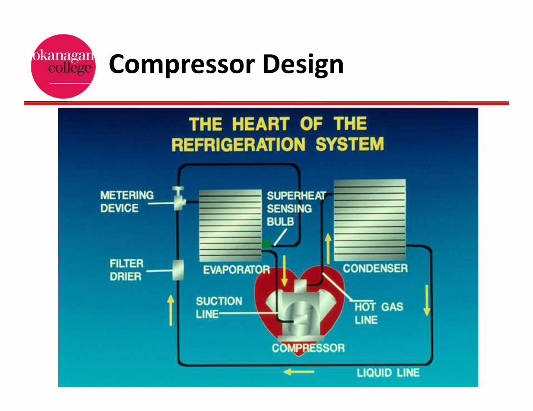
Compressor Design
Transcript of Compressor Design - PBworksokanagancollegefoundationrefrigeration.pbworks.com/w/file/fetch/... ·...

Compressor Design
Compressor Design

Compressor Design

Compressor Design

Refrigeration Cycle

Compressor Design

Mass Flow Rates @ Conditions
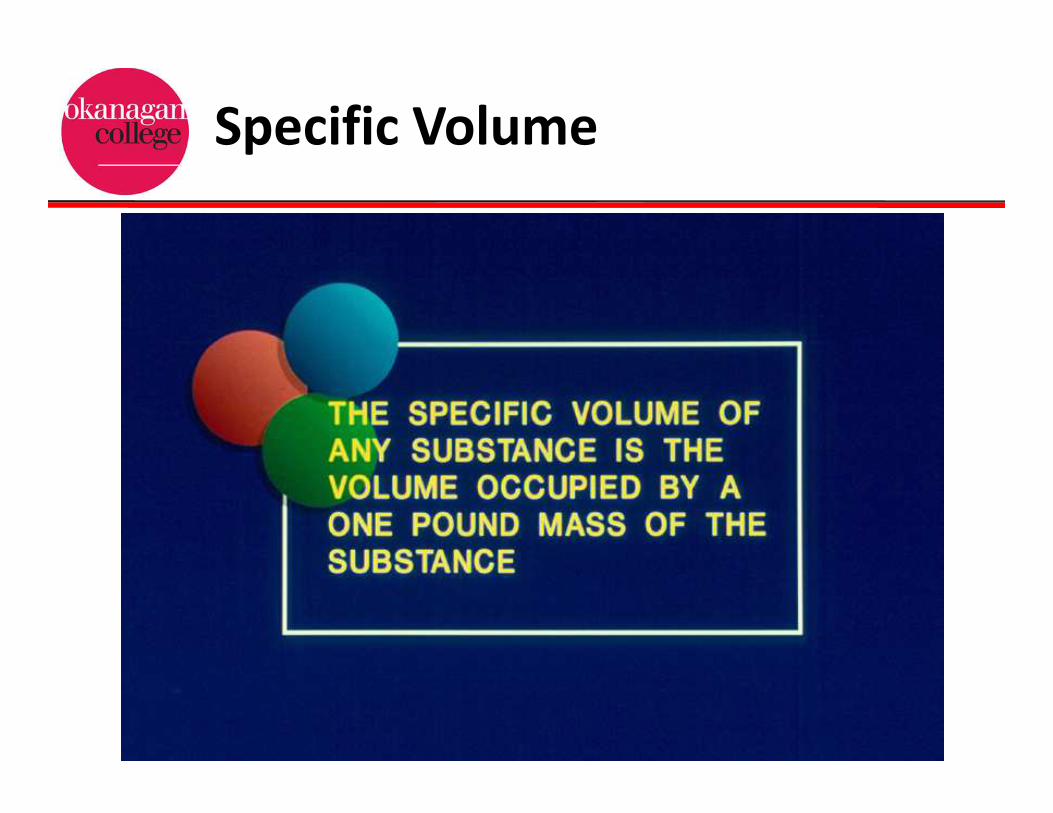
Specific Volume

Comparison: Pressure-Sp. Vol.

Specific Volume
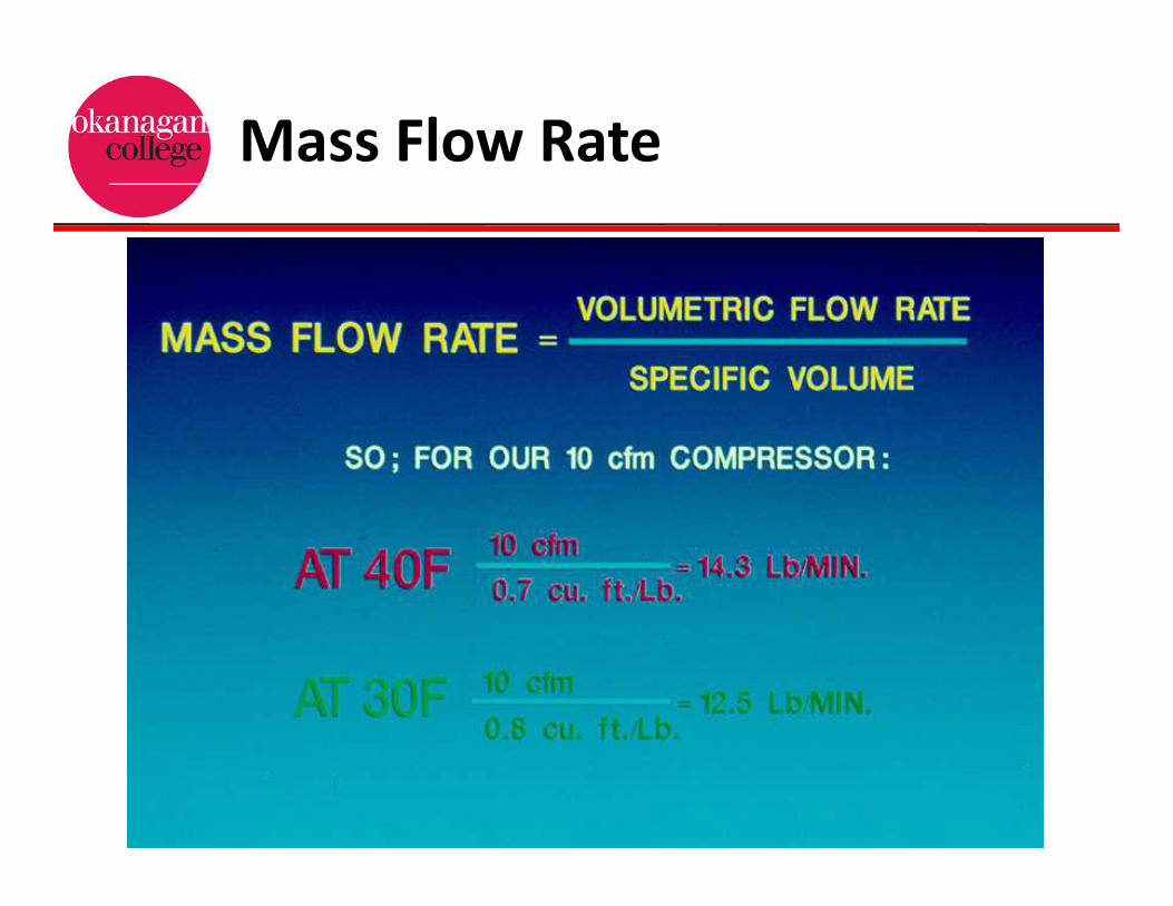
Mass Flow Rate

Compressor Capacity
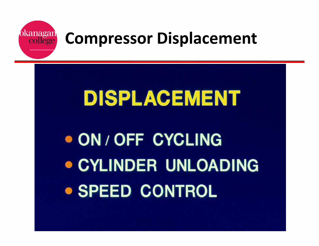
Compressor Displacement
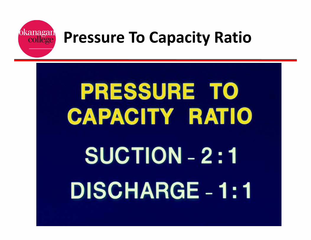
Pressure To Capacity Ratio

Compression Ratio
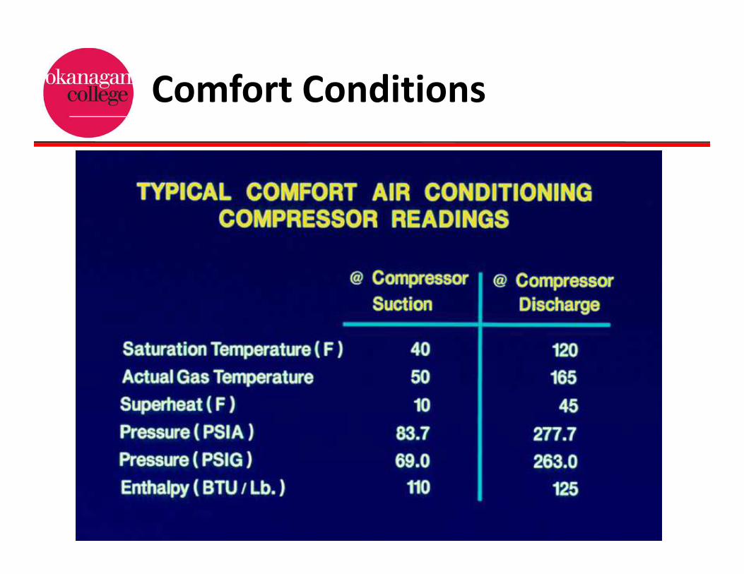
Comfort Conditions

Compressor Types
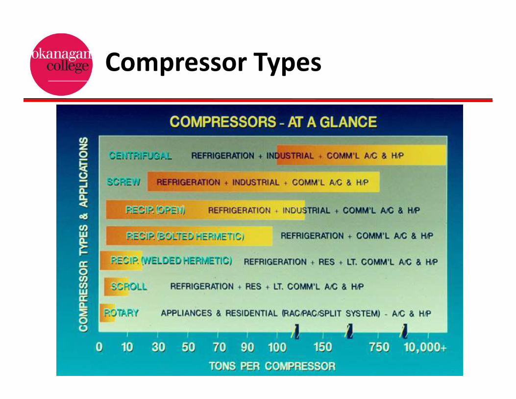
Compressor Types

Compressor Design
•Positive Displacement Pump
•Non-Positive displacement Pump

Reciprocating Compressor

Cylinder Volume/Pressure
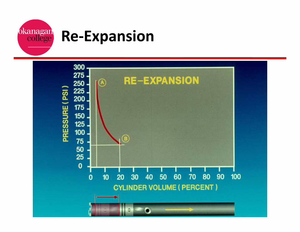
Re-Expansion

Suction

Compression

Discharge

Actual Compression Cycle
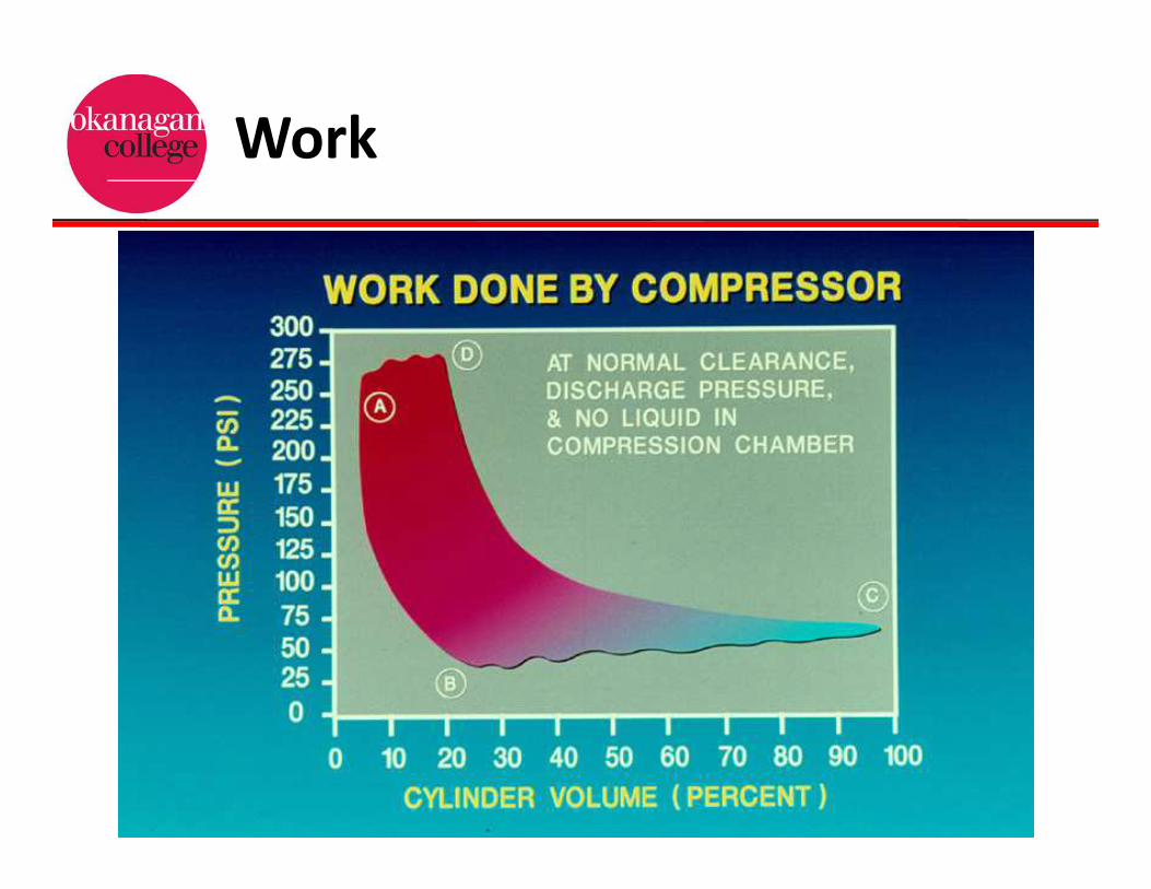
Work

Work
Result of re-expansion
Due to excessive
Discharge pressure

Reciprocating Compressors

Hermetic Compressor
•Hermetic compressors employ a an electric
motor and compressor unit sealed inside a
steel enclosure.
•These compressors can NOT be taken apart
for service, the compressor pump is directly
driven by the electric motor.

Welded Hermetic Design

Semi-Hermetic Type
•Semi-hermetic compressors are bolted
together using gaskets to form a hermetic seal.
•The electric drive motor is located within the
casing of the compressor, along with the
compressor pump.
•These compressors can be taken apart for
service.
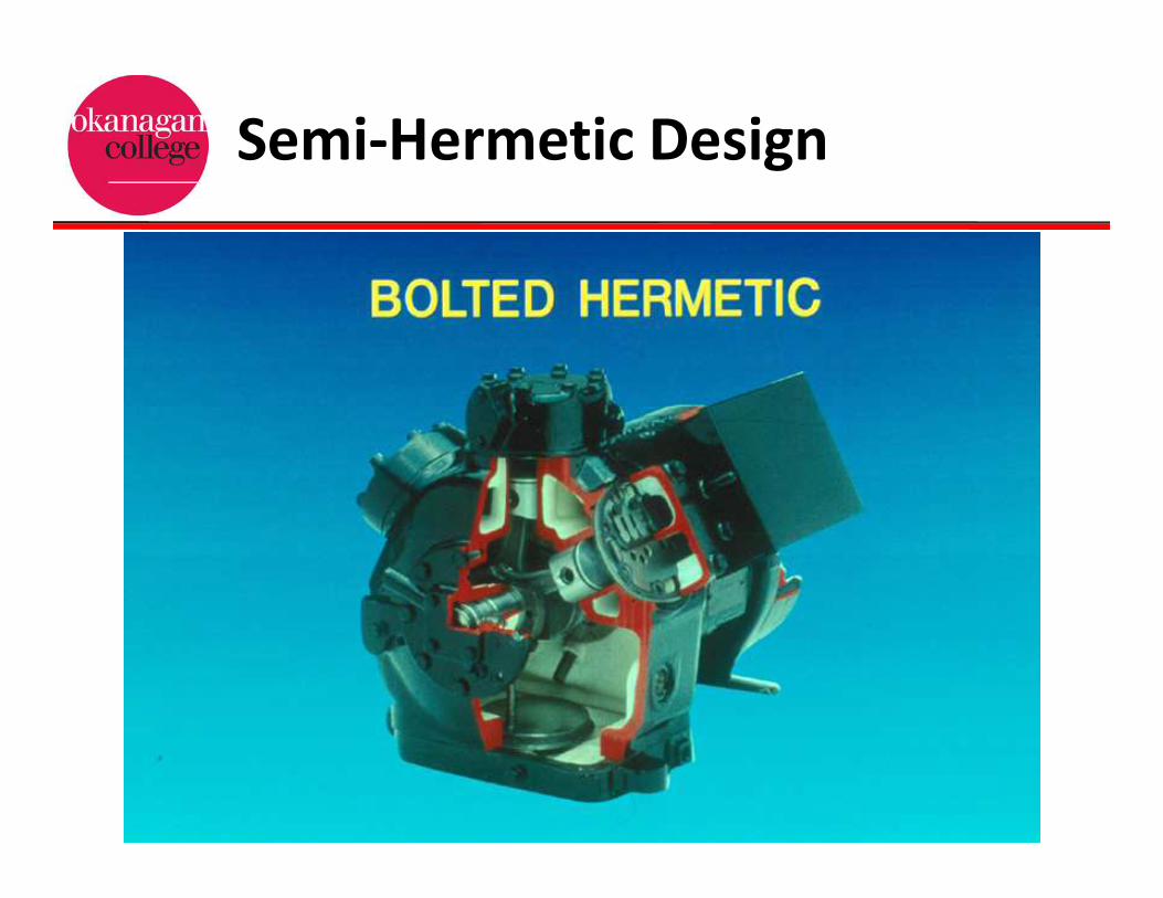
Semi-Hermetic Design
Open Drive Compressors
•The open drive type compressor contains
utilizes a separate drive motor.
•The drive shaft of the open type compressor
exits the side of the compressor connecting to
the drive system.
•The open drive uses a bolted together
construction, implementing seals and gaskets
to prevent refrigerant and oil leakage, as well
as contaminant infiltration.

Open Drive

Open Drive/ Direct Coupled

Belt Drive

Positive Displacement
•Reciprocating
•Rotary
•Both of these designs employ a mechanical
method where a volume of refrigerant is
reduced, thereby increasing it’s pressure.
Positive Displacement
•In a reciprocating compressor, a piston
moving in a cylinder reduces the volume
occupied by the refrigerant.
•Rotary compressors use a roller, vane, lobe or
scroll to reduce the volume of space occupied
by the vapor.

Open and Closed Types
•Compressors are further classified by their
construction types.
•Open Drive
•Hermetic
•Semi-Hermetic
Reciprocating Compressors
•The reciprocating compressor is the most
widely used compressor in the refrigeration
industry.
•The recip is used with all types of refrigerants,
and a wide range of applications.
•The reciprocating compressor can be divided
into two categories, the single or double acting
type.
Reciprocating Compressors
•The single acting reciprocating compressor
only compresses vapor on one side of the
piston.
•The double acting type compresses vapor on
both sides of the piston.
•The single acting reciprocating compressor is
the commonly utilized design in the
refrigeration industry today.

Rolling Piston Rotary

Sliding Vane Rotary

Rotary Compressors
•The rotary compressor can be classified into
four categories.
•The rolling piston
•Rotating Vane
•Helical Rotary (Screw)
•Scroll

Rotary Compressors
•The rotary compressor produce a smoother,
nearly constant flow of the discharge and
suction vapors.
•This operating characteristic reduces vapor
pulsations and noise by these compressors.
•Like reciprocating compressors rotary
compressors suffer from efficiency losses, but
they are generally less.

Rolling Piston Rotary
•Also known as the stationary vane rotary
compressor.
•This design employs a roller on an eccentric
shaft that glides the roller against the
stationary vane squeezing the refrigerant.

Rotating Vane Rotary
•This compressor is similar to the Rolling Piston
design.
•Except the roller has several spring loaded
vanes that are rotated on the eccentric shaft.
•As the space between the roller and the vane
is narrowed, this increases the pressure of the
refrigerant.

Helical Rotary (Screw)
•In this design compression is accomplished by
the meshing of two mating helically grooved
steel rotors.
•The male rotor consists of a series of lobes
along it’s length that mesh with the formed
helical flutes on the female rotor.
•The female rotor is driven by the turning
motion of the male rotor.

Screw Compressor

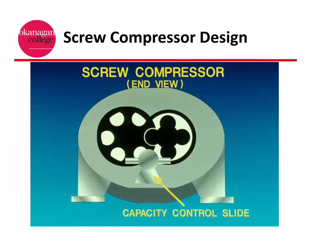
Screw Compressor Design
Screw Compressor Design

Screw Compressor Design

Screw Compressor Design

Helical Rotary (Screw)
•As the rotors turn suction vapor is drawn into
the space between the female flute and the
cylinder wall.
•This vapor becomes sealed between an
interlobe space and the cylinder wall as the
male lobe meshes with the female flute.
•The space occupied by the refrigerant vapor is
continuously reduced as the lobes mesh.
Helical Rotary (Screw)
•Twin screw compressors employ a unique
design of capacity control.
•In this design a sliding valve is utilized to open
a by-pass passage that allows refrigerant to
enter in the compression cycle later.
•The turn-down ratio on a capacity slide valve
is 90%.

Helical Rotary (Screw)
•Rotary compressors utilize very elaborate
lubrication systems.
•The use an oil pump, oil separator, oil receiver,
means of oil cooling, and all associated filters and
safeties.
•Rotary compressors utilize oil injection lubrication,
to lubricate and provide internal cooling, preventing
compressor overheating.
• This allows for compression ratios as high as 25 to
1, this allows for single stage compression.

Screw Capacity Control

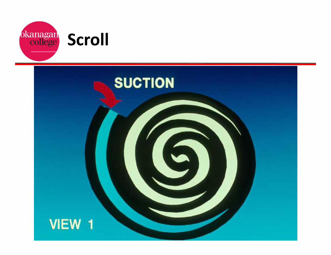
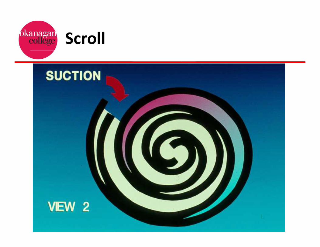
Scroll Compressor
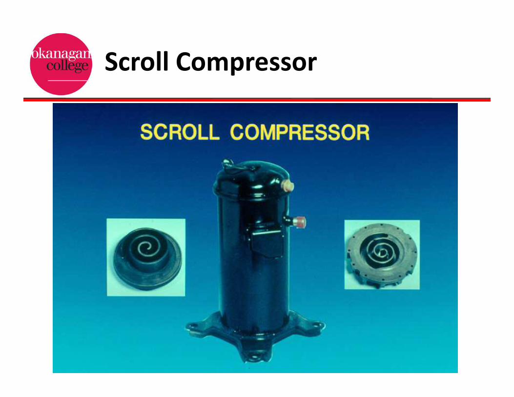
•In a scroll compressor the compression unit
consists of two matching scrolls, which when
placed together form a series of vapor pockets.
•The top scroll remains stationary, while the
bottom scroll is driven by the drive motor.
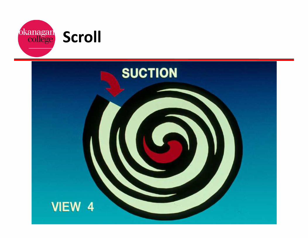
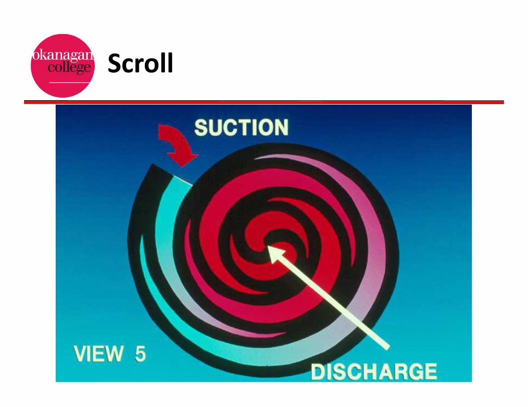
•The bottom scroll moves in an orbital motion,
squeezing the refrigerant vapor into a smaller
and smaller space.

Compressor Design
Scroll Compressor
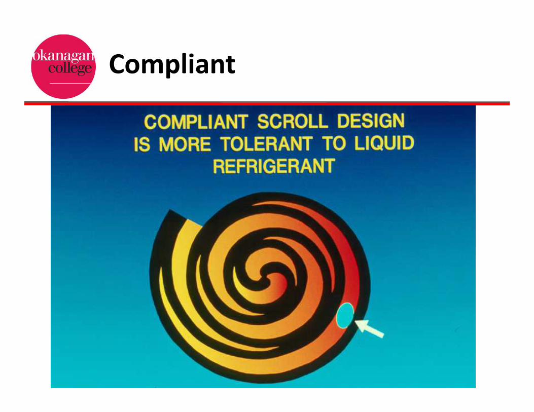
•The scroll compressor employs a COMPLIANT
design that gives it superior tolerance to liquid
refrigerant.
•In the presence of liquid refrigerant the scrolls
are allowed to separate, passing the liquid
refrigerant.
•This compliant design improves the durability
of the compressor, reducing the need for
accumulators or crankcase heaters.
Scroll Compressor
Scroll
Scroll

Scroll
Scroll
Scroll

Hermetic Scroll Design
Compliant

Non-Positive Displacement
•Centrifugal compressors are non-positive
displacement compressors.
•This design utilizes an impeller to spin the
fluid at high speed and expel it into the volute.
•As the high speed vapor enters the volute
most of the velocity pressure is converted into
static pressure, forcing the vapor out of the
volute.

Non-Positive Displacement
•Centrifugal compressors are of the non-
positive displacement type, they do not
produce pulsations in refrigerant flow.
•The spinning impeller increases the
momentum of the vapor, thereby increasing
it’s velocity and pressure before it’s discharged
into the condenser.
•Each impeller inside a centrifugal compressor
represents one stage of compression.

Centrifugal Compressor

Centrifugal Design

Centrifugal Design
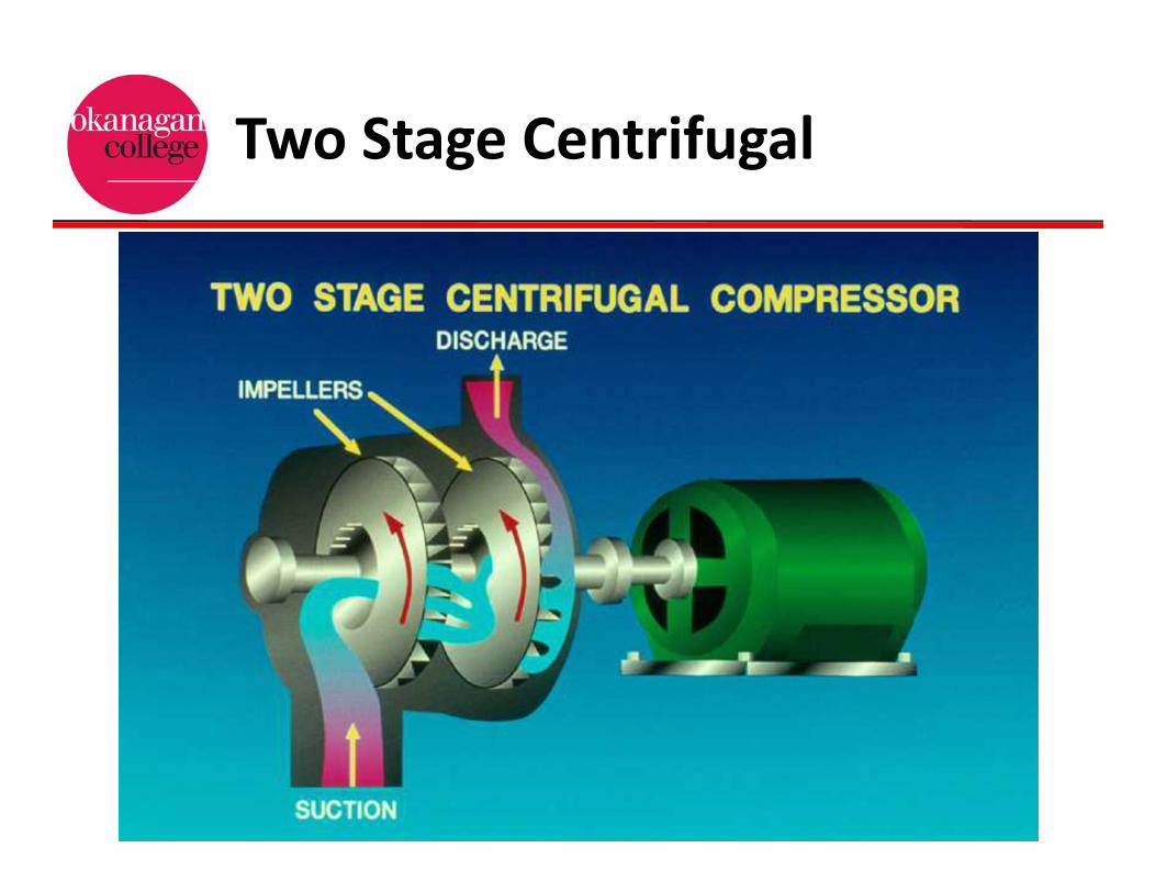
Two Stage Centrifugal

Open Drive Centrifugal

Centrifugal Compressors
•Compressors employing two, three and four
impellers is common, but additional impellers
may be used to meet the design pressures.
•The impeller is the only moving part inside
the centrifugal compressor.
•The operating principle of the centrifugal
compressor are similar to those of centrifugal
fan or pump.

Centrifugal Compressors
•The leakage between multistage compressors
is minimized by the use of labyrinth-type seals.
•The labyrinth seal is located between the
impeller’s rotor shaft, and the stationary
partitions.
•A labyrinth seal is a series of grooves
positioned side-by-side minimizing the
pressure differential of adjoining grooves,
effectively limiting transfer of vapour.

Centrifugal Compressors
•The labyrinth seal consists of several thin
strips of steel that are fastened to the rotor.
•Capacity control in centrifugal compressors is
generally accomplished by adjustable inlet
guide vanes, called pre-rotation vanes.
•There is a lower limit to the available capacity
control of centrifugal compressor.
•Lowering the capacity bellow this limit causes
surging.
Centrifugal Compressors
•Surging occurs when the energy contained in
the high side vapor exceeds the energy that
can be added to the low side vapor by the
spinning impeller.
•This condition causes the refrigerant flow to
actually reverse and flow back into the
impeller from the high side of the system.
•Surging generates abnormal noise, heat and
vibration that can damage the impeller.

Compressors
Questions

Causes of Compressor Failure

Compressor Design

Compressor Motor Cooling
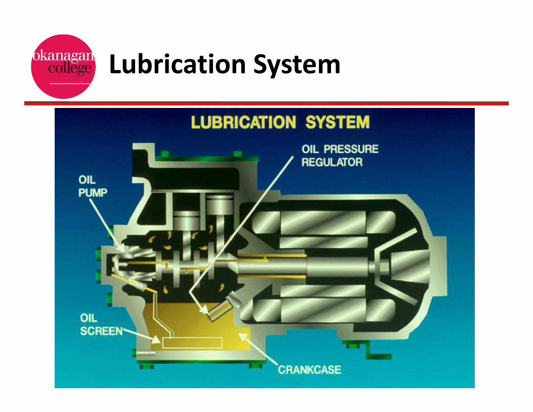
Lubrication System

Compressor Capacity
Compressor Design

Compressor Design

Compressor Design


![[Date] - Grumman/Butkusgrummanbutkus.com/.../Draft_I2SL_Higher_Ed_Labs_Report.docx · Web viewTypically, the compressor loading of a chiller is varied using inlet vanes on the impeller.](https://static.fdocuments.in/doc/165x107/5aabc9047f8b9a693f8c61ad/date-grumman-viewtypically-the-compressor-loading-of-a-chiller-is-varied-using.jpg)