Compressive response of multilayered pyramidal lattices during underwater … · ·...
13
International Journal of Impact Engineering 35 (2008) 1102–1114 Compressive response of multilayered pyramidal lattices during underwater shock loading Haydn Wadley a , Kumar Dharmasena a, , Yungchia Chen b , Philip Dudt b , David Knight b , Robert Charette b , Kenneth Kiddy c a Department of Materials Science & Engineering, University of Virginia, Charlottesville, VA 22904, USA b Naval Surface Warfare Center, Carderock, MD 20817, USA c Indian Head Division, Naval Surface Warfare Center, Indian Head, MD 20640, USA Received 3 April 2006; received in revised form 1 June 2007; accepted 1 June 2007 Available online 14 July 2007 Abstract The quasi-static and dynamic compressive mechanical response of a multilayered pyramidal lattice structure constructed from stainless-steel was investigated. The lattices were fabricated by folding perforated 304 stainless steel sheets and bonding them to thin intervening sheets using a transient liquid-phase bonding technique. The resulting structure was attached to thick face sheets and the through thickness mechanical response was investigated quasi-statically and dynamically, in the latter case using a planar explosive loading technique. The lattice is found to crush in a progressive manner by the sequential (cooperative) buckling of truss layers. This results in a quasi-static stress strain response that exhibits a significant ‘‘metal foam’’ like stress plateau to strains of about 60% before rapid hardening due to truss impingement with the intermediate face sheets. During dynamic loading, sequential buckling of the truss layers was manifested as a series of transmitted pressure pulses measured at the back face of the test samples. The sequential buckling extended the duration of the back face pressure–time waveform and significantly reduced the transmitted pressure measured at the back face. The impulse transmitted to the structure is found to be about 28% less than that predicted by analytic treatments of the fluid- structure interaction for fully supported structures. This transmitted impulse reduction appears to be a consequence of the wet side face sheet movement away from the blast wave and is facilitated by the low crush resistance of the lattice structure. r 2007 Elsevier Ltd. All rights reserved. Keywords: Compressive response; Sandwich panels; Pyramidal lattice; Impulse loading 1. Introduction There is a growing interest in extending shock protection concepts developed for low-velocity impacts (such as component packaging, head impact protection and vehicle occupant injury prevention during automobile accidents) [1] to the high-intensity, dynamic loading situations encountered when explosively created shock waves impinge upon structures [2–4]. Numerous blast mitigation ap- proaches can be envisioned including increasing the strength or mass of protective structures, using impact energy absorbing schemes [5], adding polymer coatings/ films to retard fracture [6] and perhaps the use of active approaches that cancel in whole or in part, the momentum imparted to a structure by a shock wave [7]. In the blast- loading situation, the deformation rates of structures correspond to velocities of motion in the 100 m/s or greater range [8]. This is more than an order of magnitude greater than those typically encountered in automobile collisions and most other impact events [1]. Dynamic effects might therefore be more significant and need to be addressed during design of blast mitigation structures. One approach to blast mitigation exploits crushable cellular materials [1]. Consider the processes that follow an underwater explosion near a sandwich panel structure with a cellular topology core (Fig. 1). Within the explosive, detonation converts solids to gases across a detonation front that propagates at speeds of 5000–10,000 m/s [9]. The solid to vapor transition results in a highly pressurized ARTICLE IN PRESS www.elsevier.com/locate/ijimpeng 0734-743X/$ - see front matter r 2007 Elsevier Ltd. All rights reserved. doi:10.1016/j.ijimpeng.2007.06.009 Corresponding author. E-mail address: [email protected] (K. Dharmasena).
Transcript of Compressive response of multilayered pyramidal lattices during underwater … · ·...
ARTICLE IN PRESS
0734-743X/$ - s
doi:10.1016/j.iji
�CorrespondE-mail addr
International Journal of Impact Engineering 35 (2008) 1102–1114
www.elsevier.com/locate/ijimpeng
Compressive response of multilayered pyramidal lattices duringunderwater shock loading
Haydn Wadleya, Kumar Dharmasenaa,�, Yungchia Chenb, Philip Dudtb, David Knightb,Robert Charetteb, Kenneth Kiddyc
aDepartment of Materials Science & Engineering, University of Virginia, Charlottesville, VA 22904, USAbNaval Surface Warfare Center, Carderock, MD 20817, USA
cIndian Head Division, Naval Surface Warfare Center, Indian Head, MD 20640, USA
Received 3 April 2006; received in revised form 1 June 2007; accepted 1 June 2007
Available online 14 July 2007
Abstract
The quasi-static and dynamic compressive mechanical response of a multilayered pyramidal lattice structure constructed from
stainless-steel was investigated. The lattices were fabricated by folding perforated 304 stainless steel sheets and bonding them to thin
intervening sheets using a transient liquid-phase bonding technique. The resulting structure was attached to thick face sheets and the
through thickness mechanical response was investigated quasi-statically and dynamically, in the latter case using a planar explosive
loading technique. The lattice is found to crush in a progressive manner by the sequential (cooperative) buckling of truss layers. This
results in a quasi-static stress strain response that exhibits a significant ‘‘metal foam’’ like stress plateau to strains of about 60% before
rapid hardening due to truss impingement with the intermediate face sheets. During dynamic loading, sequential buckling of the truss
layers was manifested as a series of transmitted pressure pulses measured at the back face of the test samples. The sequential buckling
extended the duration of the back face pressure–time waveform and significantly reduced the transmitted pressure measured at the back
face. The impulse transmitted to the structure is found to be about 28% less than that predicted by analytic treatments of the fluid-
structure interaction for fully supported structures. This transmitted impulse reduction appears to be a consequence of the wet side face
sheet movement away from the blast wave and is facilitated by the low crush resistance of the lattice structure.
r 2007 Elsevier Ltd. All rights reserved.
Keywords: Compressive response; Sandwich panels; Pyramidal lattice; Impulse loading
1. Introduction
There is a growing interest in extending shock protectionconcepts developed for low-velocity impacts (such ascomponent packaging, head impact protection and vehicleoccupant injury prevention during automobile accidents)[1] to the high-intensity, dynamic loading situationsencountered when explosively created shock waves impingeupon structures [2–4]. Numerous blast mitigation ap-proaches can be envisioned including increasing thestrength or mass of protective structures, using impactenergy absorbing schemes [5], adding polymer coatings/films to retard fracture [6] and perhaps the use of active
ee front matter r 2007 Elsevier Ltd. All rights reserved.
mpeng.2007.06.009
ing author.
ess: [email protected] (K. Dharmasena).
approaches that cancel in whole or in part, the momentumimparted to a structure by a shock wave [7]. In the blast-loading situation, the deformation rates of structurescorrespond to velocities of motion in the 100m/s or greaterrange [8]. This is more than an order of magnitude greaterthan those typically encountered in automobile collisionsand most other impact events [1]. Dynamic effects mighttherefore be more significant and need to be addressedduring design of blast mitigation structures.One approach to blast mitigation exploits crushable
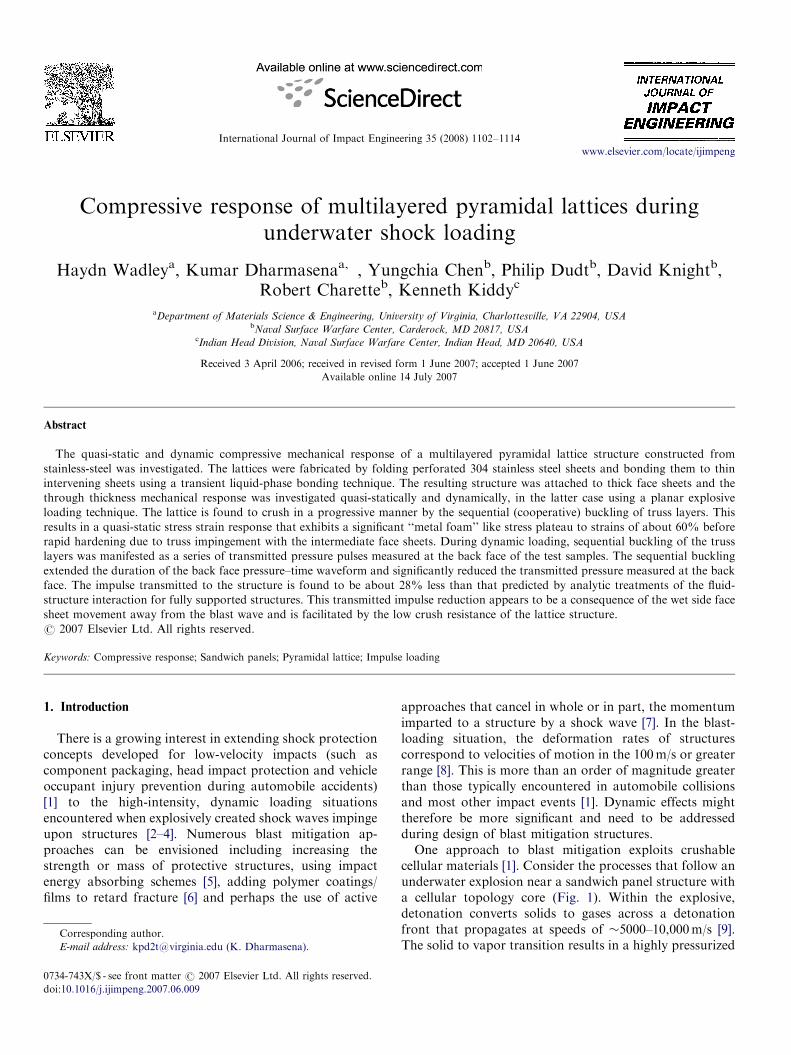
cellular materials [1]. Consider the processes that follow anunderwater explosion near a sandwich panel structure witha cellular topology core (Fig. 1). Within the explosive,detonation converts solids to gases across a detonationfront that propagates at speeds of �5000–10,000m/s [9].The solid to vapor transition results in a highly pressurized
ARTICLE IN PRESS
Fig. 1. Schematic illustration of the protection of a structure using a
cellular metal core sandwich panel. For an explosion (here in water), blast
wave mitigation is achieved by control of the fluid-structure interaction at
the face sheet–water interface and by core collapse and face sheet
stretching of the structure. (a) Before explosion; (b) after explosion.
H. Wadley et al. / International Journal of Impact Engineering 35 (2008) 1102–1114 1103
gas bubble (with internal pressures of 1–10GPa). Thebubble rapidly expands, initially at the detonation velocityof the explosive. This is greatly in excess of the acousticsound speed in water (�1400m/s). This supersonicallyforces water outwards, creating an intense high-speedshock wave traveling towards the sandwich structure.Nonlinear effects in water are less significant than those inair and the blast front speed quickly approaches theacoustic velocity limit.
The pressure pulse in water rises sharply (with a rise timeof tens of microseconds established by the detonation timeof the explosive) and then decays with a characteristic timeconstant, t0. The decay in pressure, p(t), can be approxi-mated as
pðtÞ ¼ p0e�t=t0 , (1)
where p0 is the peak pressure, t the time measured from thepeak in pressure and t0 is a characteristic time constant.
The impulse per unit area, I0, transported by the pressurepulse is given by
I0 ¼
Z 10
pðtÞdt ¼ p0t0. (2)
When the pressure pulse impinges upon a rigid, fullysupported solid plate (one that is restricted from movingaway from the blast wave), the incident pulse is reflectedfrom the surface back into the water [10]. At the surface ofthe plate, the pressures of the two disturbances are inphase, and Taylor [10] and others have shown that theplate is subjected to a peak pressure 2p0, and thetransferred momentum is 2I0. Taylor also calculated themomentum imparted to unsupported solid plates that wereable to freely accelerate in response to the applied pressureand showed that the transferred impulse was governed bythe mass/unit area of the plate. Thick solid plates wereshown to receive the same impulse as rigid, fully supportedstructures but thin face sheets pick up much less impulsebecause they are able to move away from the blast [10].When a plate moves with velocity Vf, the fluid elements
(with density rw and sound speed cw) close to the platemove with the same velocity and a rarefaction wave ofmagnitude rwcwVf is radiated back into the fluid. The netwater pressure due to the incident, reflected and rarefactionwaves results in a total plate loading:
pðtÞ ¼ 2p0e�t=t0 � rwcwV f . (3)
For a sandwich panel, it has been assumed that thefluid–structure interaction is controlled by the front (wetside) face sheet and the relevant mass per unit area can betaken as that of the front face sheet [11]. In this case, theimpulse transmitted into the sandwich structure dependsonly upon the thickness of the front face sheet and thedensity of the material it is made of. The impulse, I,transferred to the front face of an unsupported sandwichstructure is then given by [10,11]
I ¼ 2I0qq=ð1�qÞ, (4)
where
q ¼rwcw
rhft0, (5)
in which r is the density of the face sheet material and hf isthe thickness of the face sheet. The rhf product is also themass per unit area, mf, of the face sheet. If rw ¼ 1000 kg/m3, cw ¼ 1400ms�1, t0 ¼ 0.1ms and mf ¼ 40 kg/m2
(equivalent to a 5mm thick 304 stainless-steel plate),q ¼ 3.5. For sandwich panel structures with steel face sheetthicknesses in the 5mm range, Eq. (4) indicates that theimpulse transmitted from water to the sandwich structureis around 0.35 times that incident on a thick rigid plate, orone that is fully back supported. This impulse reductionarises because the front face is able to move away from thepressure pulse.However, neither Taylor’s analysis nor several recent
applications of it [11–13], fully address the fluid-structure
ARTICLE IN PRESS
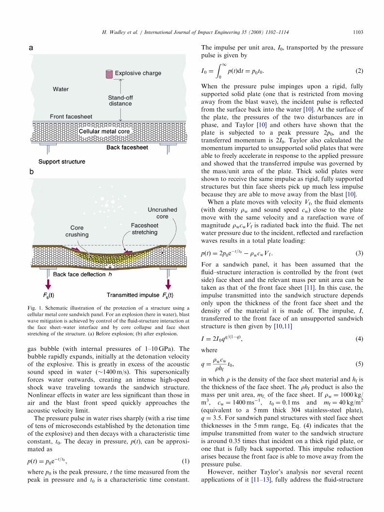
Fig. 2. Dynamic core crushing of a cellular core sandwich panel used to
reduce the peak pressure applied to the back face support structure.
H. Wadley et al. / International Journal of Impact Engineering 35 (2008) 1102–11141104
interaction for the sandwich panel problem. The initialfront face velocity of the sandwich structure is reduced bythe deformation resistance of the core and the waterattached to the front face is then able to reload thestructure. This results in an increase of the momentumtransfer by a factor that depends on the core strength[11–14] and inertial effects at high velocities. In the solidplate situation analyzed by Taylor, the tensile reflectedwave in water results in cavitation at the water–plateinterface. However, in a sandwich panel structure, cavita-tion can be delayed (by rapid acceleration of the light frontface) and the plane of tensile failure in the water thenoccurs some distance above the front face. The additionalloading depends upon the velocity of the front face sheet,which is established by the momentum originally impartedto it and the front face retarding force resulting from thecrushing resistance of the cellular material. Hutchinson andXue [13] and Liang et al. [15] have recently shown that thecore’s dynamic crush strength, scyD scaled by p0 governs theadditional impulse transferred to the core.
In this modified Taylor scenario [13,15], the momentumper unit area transferred to the front face sheet and theadded water layer is given by
IT ¼ I0 2qq=ð1�qÞ þ 1:27scyDp0
½1� qq=ð1�qÞ�
� �. (6)
For a core with a dynamic strength of 0.15p0 [13], the ratioof the total momentum of the front face sheet and addedwater layer to the incident impulse, IT/I0 is �0.5 comparedto 0.35 for a freely moving target surface. Various groupshave sought to develop a fuller understanding of theseextended Taylor effects [13–16].
There are many ways to create a sandwich panelstructure of the type schematically illustrated in Fig. 1[17]. The mass of the system can be distributed in differentways between the two faces and the core. Recent analysishas indicated that the mass distribution significantly affectsthe sandwich panel’s performance during water blastloading [15]. Analytical and numerical studies also indicatethat the strength and topology of the cellular core have asignificant effect upon the dynamic response of the system[12,13,15]. Many core topologies for metallic systems havebegun to be theoretically assessed [18]. Broadly, they can beclassified as honeycombs, lattice trusses, prismatic struc-tures and foams. Several groups have used small-scaleimpact testing and numerical analysis to probe the dynamicresponse of these different structures and to experimentallyascertain those best suited for blast mitigation applications[19–23].
Several guiding design rules are emerging from thesestudies. The dynamic core crushing resistance, scyD, isimportant since it contributes to the forces that dampthe front face motion and governs the loads applied to thesupport structure. High core strengths also ensure thatthe face sheets of the panel remain well separated so thatthe structure retains a high bending resistance. The corealso needs to possess significant in-plane stretching
resistance to impede bending deflections (Fig. 1). The idealcore will depend upon the protection strategy. Coresoptimized for reducing the peak transmitted pressure tothe sandwich panel supports might be different from thoseseeking to minimize back face deflection, or the avoidanceof front face sheet tearing or shear off at hard points.The notional behavior of an idealized lattice truss core
panel for peak shock pressure mitigation is schematicallyillustrated in Fig. 2. The system (Fig. 2(a)) consists of acellular structure with a nominal stress–plastic strainresponse during through thickness compression shown inFig. 2(b). Under quasi-static loading, this response ischaracterized by lattice collapse at a fixed, plateau stress,scy, until a plastic densification strain, eD, is reached whereupon cell wall/truss interference and friction cause a rapidincrease in strength. The plateau stress is a function of theloading rate if the core is made from strain rate hardeningmaterials and if the deformation velocity is sufficiently highthat inertial stabilization of the (buckling) failure modesoccurs [24].
ARTICLE IN PRESSH. Wadley et al. / International Journal of Impact Engineering 35 (2008) 1102–1114 1105
Suppose a faceplate with a mass, mf, per unit area isattached to the front and back of a lattice core. When ablast wave arrives at the front face of the system, a fluid-structure interaction occurs and momentum is transferredto the buffer plate. The plate then acquires a momentum mf
Vf per unit area where Vf, the initial plate velocity, variesinversely with mf. The plate’s kinetic energy is 1
2mfV
2f . The
motion of the buffer plate is retarded by the reaction forcearising from the dynamic crush strength, scyDof the latticestructure (Fig. 2(c)) and inertial effects, which becomemore important as the front face velocity increases beyond�30m/s [24]. A plastic shock wave (across which crushingoccurs) is propagated at the plastic wave speed from thefront of the cellular structure towards the back face sheet.For low front face velocities and a core with the idealmechanical response shown in Fig. 2(b), the forcetransferred to the protected structure behind the systemnever rises above scyD A (where A is the back face area)provided the crush zone deformation never exceeds thedensification strain and the crush zone front is arrestedwithin the cellular structure.
Higher velocity (420m/s) motion of the front face canresult in significant increases in the reaction force appliedto the front face. These increases result from the inertialresistance of the core (from the forces required foracceleration of the material mass in and behind the crushzone), inertial stabilization against buckling of coremembers (webs and trusses) and material hardening athigh strains and strain rates. These effects all scale with adimensionless velocity, Vf/cey, where c is the acoustic wavespeed and ey is the yield strain of the material used to createthe cellular structure [25]. Radford et al. [20,21] and Lee etal. [22] propose that for a foam core the dynamic strengthis given by
scyD ¼ scy þ rcV2f =�d, (7)
where scyD is the core strength when strain rate hardeningand inertially stabilized truss buckling are accounted for, rcthe cellular sandwich core relative density, ed the coredensification strain and Vf is the front face velocity. For abi-linear material with linear hardening rate, Xue andHutchinson have proposed a dynamic strength law of theform [25]:
scyDrcsy� 1þ
ffiffiffiffiffiEt
E
rV f
cel�y� 1
� �, (8)
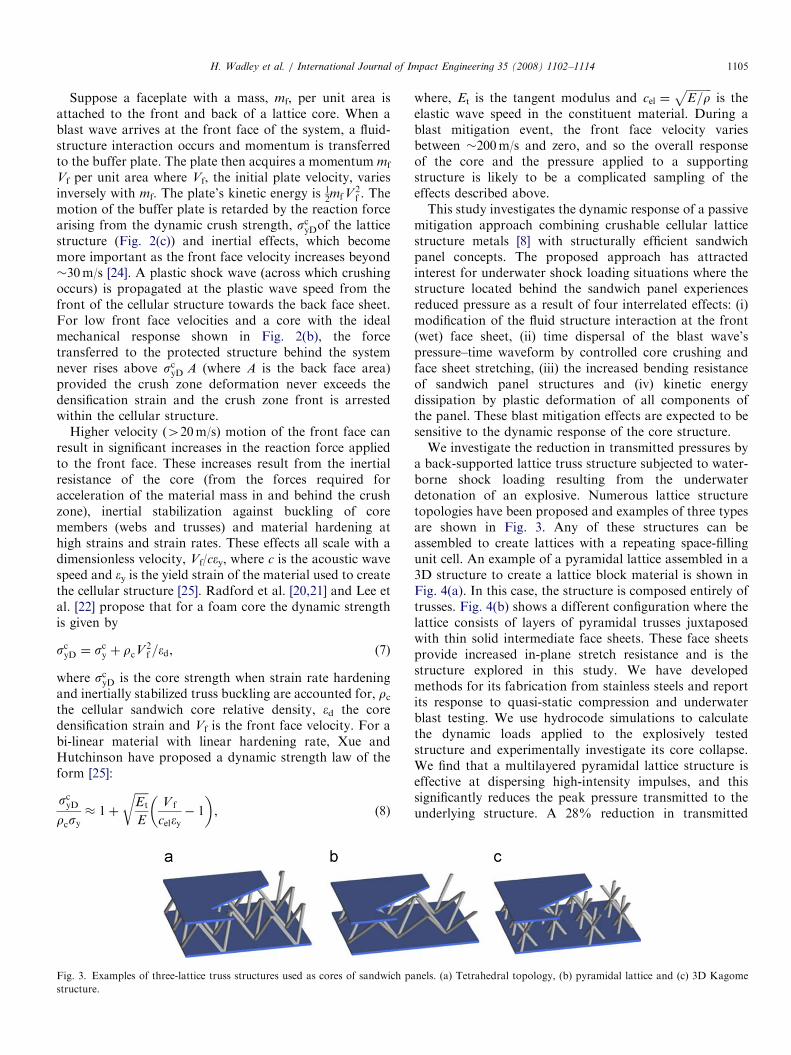
Fig. 3. Examples of three-lattice truss structures used as cores of sandwich pa
structure.
where, Et is the tangent modulus and cel ¼ffiffiffiffiffiffiffiffiffiE=r
pis the
elastic wave speed in the constituent material. During ablast mitigation event, the front face velocity variesbetween �200m/s and zero, and so the overall responseof the core and the pressure applied to a supportingstructure is likely to be a complicated sampling of theeffects described above.This study investigates the dynamic response of a passive
mitigation approach combining crushable cellular latticestructure metals [8] with structurally efficient sandwichpanel concepts. The proposed approach has attractedinterest for underwater shock loading situations where thestructure located behind the sandwich panel experiencesreduced pressure as a result of four interrelated effects: (i)modification of the fluid structure interaction at the front(wet) face sheet, (ii) time dispersal of the blast wave’spressure–time waveform by controlled core crushing andface sheet stretching, (iii) the increased bending resistanceof sandwich panel structures and (iv) kinetic energydissipation by plastic deformation of all components ofthe panel. These blast mitigation effects are expected to besensitive to the dynamic response of the core structure.We investigate the reduction in transmitted pressures by
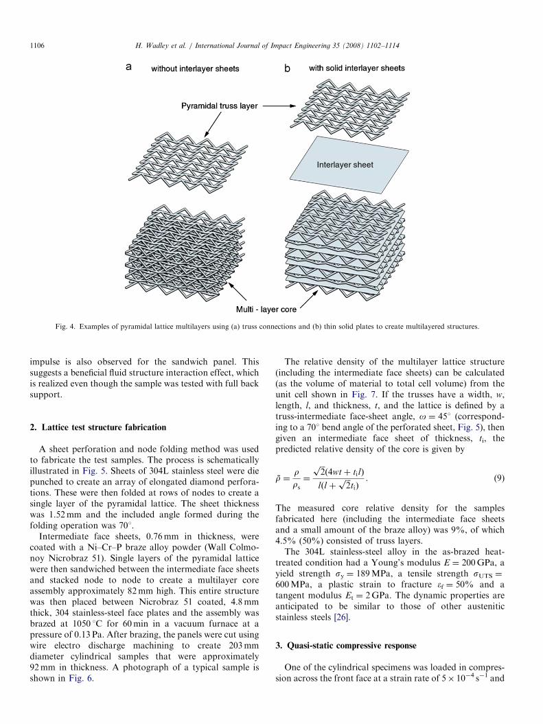
a back-supported lattice truss structure subjected to water-borne shock loading resulting from the underwaterdetonation of an explosive. Numerous lattice structuretopologies have been proposed and examples of three typesare shown in Fig. 3. Any of these structures can beassembled to create lattices with a repeating space-fillingunit cell. An example of a pyramidal lattice assembled in a3D structure to create a lattice block material is shown inFig. 4(a). In this case, the structure is composed entirely oftrusses. Fig. 4(b) shows a different configuration where thelattice consists of layers of pyramidal trusses juxtaposedwith thin solid intermediate face sheets. These face sheetsprovide increased in-plane stretch resistance and is thestructure explored in this study. We have developedmethods for its fabrication from stainless steels and reportits response to quasi-static compression and underwaterblast testing. We use hydrocode simulations to calculatethe dynamic loads applied to the explosively testedstructure and experimentally investigate its core collapse.We find that a multilayered pyramidal lattice structure iseffective at dispersing high-intensity impulses, and thissignificantly reduces the peak pressure transmitted to theunderlying structure. A 28% reduction in transmitted
nels. (a) Tetrahedral topology, (b) pyramidal lattice and (c) 3D Kagome
ARTICLE IN PRESS
Fig. 4. Examples of pyramidal lattice multilayers using (a) truss connections and (b) thin solid plates to create multilayered structures.
H. Wadley et al. / International Journal of Impact Engineering 35 (2008) 1102–11141106
impulse is also observed for the sandwich panel. Thissuggests a beneficial fluid structure interaction effect, whichis realized even though the sample was tested with full backsupport.
2. Lattice test structure fabrication
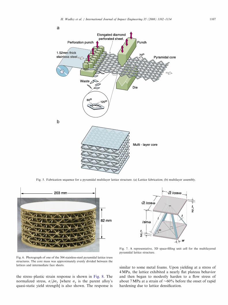
A sheet perforation and node folding method was usedto fabricate the test samples. The process is schematicallyillustrated in Fig. 5. Sheets of 304L stainless steel were diepunched to create an array of elongated diamond perfora-tions. These were then folded at rows of nodes to create asingle layer of the pyramidal lattice. The sheet thicknesswas 1.52mm and the included angle formed during thefolding operation was 701.
Intermediate face sheets, 0.76mm in thickness, werecoated with a Ni–Cr–P braze alloy powder (Wall Colmo-noy Nicrobraz 51). Single layers of the pyramidal latticewere then sandwiched between the intermediate face sheetsand stacked node to node to create a multilayer coreassembly approximately 82mm high. This entire structurewas then placed between Nicrobraz 51 coated, 4.8mmthick, 304 stainless-steel face plates and the assembly wasbrazed at 1050 1C for 60min in a vacuum furnace at apressure of 0.13 Pa. After brazing, the panels were cut usingwire electro discharge machining to create 203mmdiameter cylindrical samples that were approximately92mm in thickness. A photograph of a typical sample isshown in Fig. 6.
The relative density of the multilayer lattice structure(including the intermediate face sheets) can be calculated(as the volume of material to total cell volume) from theunit cell shown in Fig. 7. If the trusses have a width, w,length, l, and thickness, t, and the lattice is defined by atruss-intermediate face-sheet angle, o ¼ 451 (correspond-ing to a 701 bend angle of the perforated sheet, Fig. 5), thengiven an intermediate face sheet of thickness, ti, thepredicted relative density of the core is given by
r̄ ¼rrs¼
ffiffiffi2pð4wtþ tilÞ
lðl þffiffiffi2p
tiÞ. (9)
The measured core relative density for the samplesfabricated here (including the intermediate face sheetsand a small amount of the braze alloy) was 9%, of which4.5% (50%) consisted of truss layers.The 304L stainless-steel alloy in the as-brazed heat-
treated condition had a Young’s modulus E ¼ 200GPa, ayield strength sy ¼ 189MPa, a tensile strength sUTS ¼
600MPa, a plastic strain to fracture ef ¼ 50% and atangent modulus Et ¼ 2GPa. The dynamic properties areanticipated to be similar to those of other austeniticstainless steels [26].
3. Quasi-static compressive response
One of the cylindrical specimens was loaded in compres-sion across the front face at a strain rate of 5� 10�4 s�1 and
ARTICLE IN PRESS
Fig. 5. Fabrication sequence for a pyramidal multilayer lattice structure. (a) Lattice fabrication; (b) multilayer assembly.
Fig. 6. Photograph of one of the 304 stainless-steel pyramidal lattice truss
structures. The core mass was approximately evenly divided between the
lattices and intermediate face sheets.
Fig. 7. A representative, 3D space-filling unit cell for the multilayered
pyramidal lattice structure.
H. Wadley et al. / International Journal of Impact Engineering 35 (2008) 1102–1114 1107
the stress–plastic strain response is shown in Fig. 8. Thenormalized stress, s=r̄sy [where sy is the parent alloy’squasi-static yield strength] is also shown. The response is
similar to some metal foams. Upon yielding at a stress of4MPa, the lattice exhibited a nearly flat plateau behaviorand then began to modestly harden to a flow stress ofabout 7MPa at a strain of �60% before the onset of rapidhardening due to lattice densification.
ARTICLE IN PRESSH. Wadley et al. / International Journal of Impact Engineering 35 (2008) 1102–11141108
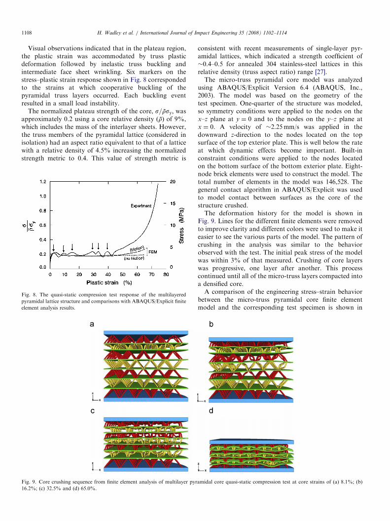
Visual observations indicated that in the plateau region,the plastic strain was accommodated by truss plasticdeformation followed by inelastic truss buckling andintermediate face sheet wrinkling. Six markers on thestress–plastic strain response shown in Fig. 8 correspondedto the strains at which cooperative buckling of thepyramidal truss layers occurred. Each buckling eventresulted in a small load instability.
The normalized plateau strength of the core, s=r̄sy; wasapproximately 0.2 using a core relative density ðr̄Þ of 9%,which includes the mass of the interlayer sheets. However,the truss members of the pyramidal lattice (considered inisolation) had an aspect ratio equivalent to that of a latticewith a relative density of 4.5% increasing the normalizedstrength metric to 0.4. This value of strength metric is
Fig. 8. The quasi-static compression test response of the multilayered
pyramidal lattice structure and comparisons with ABAQUS/Explicit finite
element analysis results.
Fig. 9. Core crushing sequence from finite element analysis of multilayer pyr
16.2%; (c) 32.5% and (d) 65.0%.
consistent with recent measurements of single-layer pyr-amidal lattices, which indicated a strength coefficient of�0.4–0.5 for annealed 304 stainless-steel lattices in thisrelative density (truss aspect ratio) range [27].The micro-truss pyramidal core model was analyzed
using ABAQUS/Explicit Version 6.4 (ABAQUS, Inc.,2003). The model was based on the geometry of thetest specimen. One-quarter of the structure was modeled,so symmetry conditions were applied to the nodes on thex–z plane at y ¼ 0 and to the nodes on the y–z plane atx ¼ 0. A velocity of �2.25mm/s was applied in thedownward z-direction to the nodes located on the topsurface of the top exterior plate. This is well below the rateat which dynamic effects become important. Built-inconstraint conditions were applied to the nodes locatedon the bottom surface of the bottom exterior plate. Eight-node brick elements were used to construct the model. Thetotal number of elements in the model was 146,528. Thegeneral contact algorithm in ABAQUS/Explicit was usedto model contact between surfaces as the core of thestructure crushed.The deformation history for the model is shown in
Fig. 9. Lines for the different finite elements were removedto improve clarity and different colors were used to make iteasier to see the various parts of the model. The pattern ofcrushing in the analysis was similar to the behaviorobserved with the test. The initial peak stress of the modelwas within 3% of that measured. Crushing of core layerswas progressive, one layer after another. This processcontinued until all of the micro-truss layers compacted intoa densified core.A comparison of the engineering stress–strain behavior
between the micro-truss pyramidal core finite elementmodel and the corresponding test specimen is shown in
amidal core quasi-static compression test at core strains of (a) 8.1%; (b)
ARTICLE IN PRESSH. Wadley et al. / International Journal of Impact Engineering 35 (2008) 1102–1114 1109
Fig. 8. The stress increased to the initial peak and thendecreased as the first core layer began to buckle and crush.The applied strain rate was accommodated by this layer’scollapse until it reached its densification strain. At thispoint, it was redistributed among the other core layers andthe stress increased to a second peak coincident with theinitiation of buckling in a second layer. This patterncontinued as each of the layers was crushed and coredensification occurred.
This lattice core design maintains a consistent level ofstrength because it has multiple layers. In the analyses,even after a layer fails, the remaining intact layers areable to support a large part of the initial peak load. TheFEM analysis stress–strain curves reflect a nearly constantload-carrying capacity after the initial peak is passedwith some modest peaks and troughs. The test stress–straincurve exhibits more pronounced peaks and troughs andhas subsequent peaks that are even higher than theinitial peak. At about 42% core strain, the stress startsto increase continuously because all of the core layershave compacted into a denser form. The core thenbegins to behave increasingly like a solid cylinderand supports larger load levels as it densifies and workhardens.
The influence of friction between truss surfaces can beseen when comparing the analysis with friction, to theanalysis without friction (Fig. 8). With friction present inthe analysis, the core behavior follows a pattern moresimilar to the behavior seen with the test. When friction isignored, it takes much longer for the stress to start acontinuous upward trend.
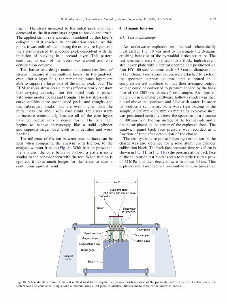
Fig. 10. Schematic illustration of the test method used to investigate the dyn
system was also conducted using a solid aluminum sample test piece of identi
4. Dynamic behavior
4.1. Test methodology
An underwater explosive test method schematicallyillustrated in Fig. 10 was used to investigate the dynamiccrushing behavior of the pyramidal lattice structure. Thetest specimens were slip fitted into a thick, high-strengthsteel cover plate with a central opening and positioned onfour HY-100 steel columns each �3.8 cm in diameter and�12 cm long. Four strain gauges were attached to each ofthe specimen support columns and calibrated in acompression test machine so that their averaged outputvoltage could be converted to pressure applied by the backface of the (203mm diameter) test sample. An approxi-mately 0.9m diameter cardboard hollow cylinder was thenplaced above the specimen and filled with water. In orderto produce a symmetric, plane wave type loading of thesample, a 203mm� 203mm� 1mm thick explosive sheetwas positioned centrally above the specimen at a distanceof 100mm from the top surface of the test sample and adetonator placed at the center of the explosive sheet. Thesandwich panel back face pressure was recorded as afunction of time after detonation of the charge.The test system’s response following detonation of the
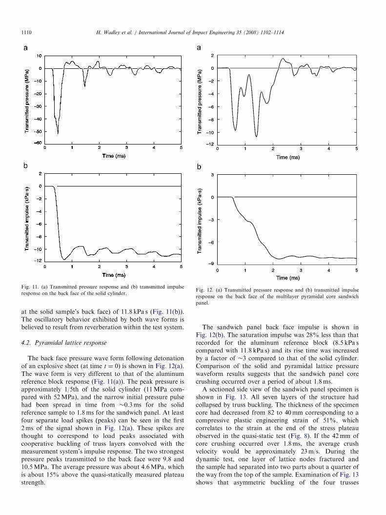
charge was also obtained for a solid aluminum cylindercalibration block. The back face pressure–time waveform isshown in Fig. 11. In Fig. 11(a) the pressure at the back faceof the calibration test block is seen to rapidly rise to a peakof 52MPa and then decay to zero in about 0.3ms. Thisexplosive event resulted in a transmitted impulse (measured
amic crush response of the pyramidal lattice structure. Calibration of the
cal dimensions to those of the sandwich panels.
ARTICLE IN PRESS
Fig. 11. (a) Transmitted pressure response and (b) transmitted impulse
response on the back face of the solid cylinder.Fig. 12. (a) Transmitted pressure response and (b) transmitted impulse
response on the back face of the multilayer pyramidal core sandwich
panel.
H. Wadley et al. / International Journal of Impact Engineering 35 (2008) 1102–11141110
at the solid sample’s back face) of 11.8 kPa s (Fig. 11(b)).The oscillatory behavior exhibited by both wave forms isbelieved to result from reverberation within the test system.
4.2. Pyramidal lattice response
The back face pressure wave form following detonationof an explosive sheet (at time t ¼ 0) is shown in Fig. 12(a).The wave form is very different to that of the aluminumreference block response (Fig. 11(a)). The peak pressure isapproximately 1/5th of the solid cylinder (11MPa com-pared with 52MPa), and the narrow initial pressure pulsehad been spread in time from �0.3ms for the solidreference sample to 1.8ms for the sandwich panel. At leastfour separate load spikes (peaks) can be seen in the first2ms of the signal shown in Fig. 12(a). These spikes arethought to correspond to load peaks associated withcooperative buckling of truss layers convolved with themeasurement system’s impulse response. The two strongestpressure peaks transmitted to the back face were 9.8 and10.5MPa. The average pressure was about 4.6MPa, whichis about 15% above the quasi-statically measured plateaustrength.
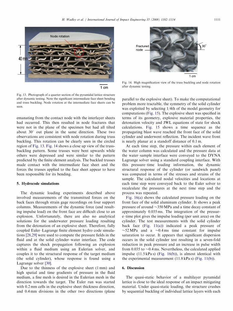
The sandwich panel back face impulse is shown inFig. 12(b). The saturation impulse was 28% less than thatrecorded for the aluminum reference block (8.5 kPa scompared with 11.8 kPa s) and its rise time was increasedby a factor of �3 compared to that of the solid cylinder.Comparison of the solid and pyramidal lattice pressurewaveform results suggests that the sandwich panel corecrushing occurred over a period of about 1.8ms.A sectioned side view of the sandwich panel specimen is
shown in Fig. 13. All seven layers of the structure hadcollapsed by truss buckling. The thickness of the specimencore had decreased from 82 to 40mm corresponding to acompressive plastic engineering strain of 51%, whichcorrelates to the strain at the end of the stress plateauobserved in the quasi-static test (Fig. 8). If the 42mm ofcore crushing occurred over 1.8ms, the average crushvelocity would be approximately 23m/s. During thedynamic test, one layer of lattice nodes fractured andthe sample had separated into two parts about a quarter ofthe way from the top of the sample. Examination of Fig. 13shows that asymmetric buckling of the four trusses
ARTICLE IN PRESS
Fig. 13. Photograph of a quarter section of the pyramidal lattice structure
after dynamic testing. Note the significant intermediate face sheet bending
and truss buckling. Node rotation at the intermediate face sheets can be
seen.
Fig. 14. High magnification view of the truss buckling and node rotation
after dynamic testing.
H. Wadley et al. / International Journal of Impact Engineering 35 (2008) 1102–1114 1111
emanating from the contact node with the interlayer sheetshad occurred. This then resulted in node fractures thatwere not in the plane of the specimen but had all tiltedabout 301 out plane in the same direction. These twoobservations are consistent with node rotation during trussbuckling. This rotation can be clearly seen in the circledregion of Fig. 13. Fig. 14 shows a close up view of the truss-buckling pattern. Some trusses were bent upwards whileothers were depressed and were similar to the patternpredicted by the finite element analysis. The buckled trussesmade contact with the intermediate face sheet and theforces the trusses applied to the face sheet appear to havebeen responsible for its bending.
5. Hydrocode simulations
The dynamic loading experiments described aboveinvolved measurements of the transmitted forces on theback faces through strain gage recordings on four supportcolumns. Measurements of the dynamic force (and result-ing impulse load) on the front face are difficult close to anexplosion. Unfortunately, there are also no analyticalsolutions for the underwater pressure loading resultingfrom the detonation of an explosive sheet. Therefore, fullycoupled Euler–Lagrange finite element hydro code simula-tions [28,29] were used to compute the pressure fields in thefluid and at the solid cylinder–water interface. The codecaptures the shock propagation following an explosionwithin a fluid medium using an Eulerian solver, andcouples it to the structural response of the target medium(the solid cylinder), whose response is found using aLagrange solver [30].
Due to the thinness of the explosive sheet (1mm) andhigh spatial and time gradients of pressure in the fluidmedium, a fine mesh is desired in the Eulerian mesh in thedirection towards the target. The Euler run was startedwith 0.2mm cells in the explosive sheet thickness direction,and 0.4mm divisions in the other two directions (plane
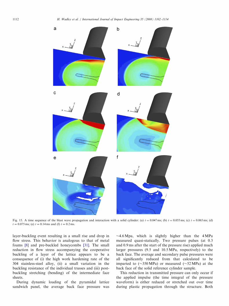
parallel to the explosive sheet). To make the computationalproblem more tractable, the symmetry of the solid cylinderwas exploited by selecting 1/4th of the model geometry forcomputations (Fig. 15). The explosive sheet was specified interms of its geometry, explosive material properties, thedetonation velocity and JWL equations of state for shockcalculations. Fig. 15 shows a time sequence as thepropagating blast wave reached the front face of the solidcylinder and underwent reflection. The incident wave frontis nearly planar at a standoff distance of 0.1m.At each time step, the pressure within each element of
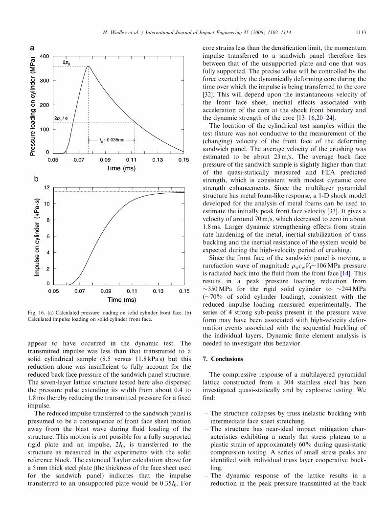
the water column was calculated and the pressure data atthe water–sample interface were conveyed to the DYNALagrange solver using a standard coupling interface. Withthis pressure–time loading information, the dynamicstructural response of the cylinder (or sandwich panel)was computed in terms of the stresses and strains of thesample. The calculated nodal velocities and locations ateach time step were conveyed back to the Euler solver torecalculate the pressures at the next time step and theprocess was repeated.Fig. 16(a) shows the calculated pressure loading on the
front face of the solid aluminum cylinder. It shows a peakpressure of around �350MPa and a time decay constant ofapproximately 0.035ms. The integration of the pressur-e–time plot gives the impulse loading (per unit area) on thecylinder. The test measurements with the solid cylinderback face (Fig. 11(a)) indicated a peak pressure of�52MPa and a �0.4ms time constant for impulsesaturation to occur. It appears that significant dispersionoccurs in the solid cylinder test resulting in a seven-foldreduction in peak pressure and an increase in pulse widthfrom 0.035 to �0.4ms. Nevertheless, the calculated appliedimpulse (11.5 kPa s) (Fig. 16(b)), is almost identical withthe experimental measurement (11.8 kPa s) (Fig. 11(b)).
6. Discussion
The quasi-static behavior of a multilayer pyramidallattice is close to the ideal response of an impact mitigatingmaterial. Under quasi-static loading, the structure crushesby sequential buckling of individual lattice layers with each
ARTICLE IN PRESS
Fig. 15. A time sequence of the blast wave propagation and interaction with a solid cylinder: (a) t ¼ 0.047ms; (b) t ¼ 0.055ms; (c) t ¼ 0.065ms; (d)
t ¼ 0.075ms; (e) t ¼ 0.14ms and (f) t ¼ 0.2ms.
H. Wadley et al. / International Journal of Impact Engineering 35 (2008) 1102–11141112
layer-buckling event resulting in a small rise and drop inflow stress. This behavior is analogous to that of metalfoams [8] and pre-buckled honeycombs [31]. The smallreduction in flow stress accompanying the cooperativebuckling of a layer of the lattice appears to be aconsequence of (i) the high work hardening rate of the304 stainless-steel alloy, (ii) a small variation in thebuckling resistance of the individual trusses and (iii) post-buckling stretching (bending) of the intermediate facesheets.
During dynamic loading of the pyramidal latticesandwich panel, the average back face pressure was
�4.6Mpa, which is slightly higher than the 4MPameasured quasi-statically. Two pressure pulses (at 0.3and 0.9ms after the start of the pressure rise) applied muchlarger pressures (9.5 and 10.5MPa, respectively) to theback face. The average and secondary pulse pressures wereall significantly reduced from that calculated to beimparted to (�350MPa) or measured (�52MPa) at theback face of the solid reference cylinder sample.This reduction in transmitted pressure can only occur if
the applied impulse (the time integral of the pressurewaveform) is either reduced or stretched out over timeduring plastic propagation through the structure. Both
ARTICLE IN PRESS
Fig. 16. (a) Calculated pressure loading on solid cylinder front face. (b)
Calculated impulse loading on solid cylinder front face.
H. Wadley et al. / International Journal of Impact Engineering 35 (2008) 1102–1114 1113
appear to have occurred in the dynamic test. Thetransmitted impulse was less than that transmitted to asolid cylindrical sample (8.5 versus 11.8 kPa s) but thisreduction alone was insufficient to fully account for thereduced back face pressure of the sandwich panel structure.The seven-layer lattice structure tested here also dispersedthe pressure pulse extending its width from about 0.4 to1.8ms thereby reducing the transmitted pressure for a fixedimpulse.
The reduced impulse transferred to the sandwich panel ispresumed to be a consequence of front face sheet motionaway from the blast wave during fluid loading of thestructure. This motion is not possible for a fully supportedrigid plate and an impulse, 2I0, is transferred to thestructure as measured in the experiments with the solidreference block. The extended Taylor calculation above fora 5mm thick steel plate (the thickness of the face sheet usedfor the sandwich panel) indicates that the impulsetransferred to an unsupported plate would be 0.35I0. For
core strains less than the densification limit, the momentumimpulse transferred to a sandwich panel therefore liesbetween that of the unsupported plate and one that wasfully supported. The precise value will be controlled by theforce exerted by the dynamically deforming core during thetime over which the impulse is being transferred to the core[32]. This will depend upon the instantaneous velocity ofthe front face sheet, inertial effects associated withacceleration of the core at the shock front boundary andthe dynamic strength of the core [13–16,20–24].The location of the cylindrical test samples within the
test fixture was not conducive to the measurement of the(changing) velocity of the front face of the deformingsandwich panel. The average velocity of the crushing wasestimated to be about 23m/s. The average back facepressure of the sandwich sample is slightly higher than thatof the quasi-statically measured and FEA predictedstrength, which is consistent with modest dynamic corestrength enhancements. Since the multilayer pyramidalstructure has metal foam-like response, a 1-D shock modeldeveloped for the analysis of metal foams can be used toestimate the initially peak front face velocity [33]. It gives avelocity of around 70m/s, which decreased to zero in about1.8ms. Larger dynamic strengthening effects from strainrate hardening of the metal, inertial stabilization of trussbuckling and the inertial resistance of the system would beexpected during the high-velocity period of crushing.Since the front face of the sandwich panel is moving, a
rarefaction wave of magnitude rwcwVf�106MPa pressureis radiated back into the fluid from the front face [14]. Thisresults in a peak pressure loading reduction from�350MPa for the rigid solid cylinder to �244MPa(�70% of solid cylinder loading), consistent with thereduced impulse loading measured experimentally. Theseries of 4 strong sub-peaks present in the pressure waveform may have been associated with high-velocity defor-mation events associated with the sequential buckling ofthe individual layers. Dynamic finite element analysis isneeded to investigate this behavior.
7. Conclusions
The compressive response of a multilayered pyramidallattice constructed from a 304 stainless steel has beeninvestigated quasi-statically and by explosive testing. Wefind:
–
The structure collapses by truss inelastic buckling withintermediate face sheet stretching.–
The structure has near-ideal impact mitigation char-acteristics exhibiting a nearly flat stress plateau to aplastic strain of approximately 60% during quasi-staticcompression testing. A series of small stress peaks areidentified with individual truss layer cooperative buck-ling.–
The dynamic response of the lattice results in areduction in the peak pressure transmitted at the back
ARTICLE IN PRESSH. Wadley et al. / International Journal of Impact Engineering 35 (2008) 1102–11141114
face (11 versus 52MPa for a solid structure) anddisperses the pressure waveform resulting in a waveformwidth increase from 0.35 to �1.8ms.
–
The dynamic compressive response indicates a series ofhardening/softening phases with pressures transmittedto the back face varying from a low of 1MPa to amaximum of 11MPa with an average slightly above thequasi-statically measured core strength. These softeningphases are thought to be a consequence of thecooperative collapse of one or more truss layers duringprogressive propagation of a densification front throughthe structure. Further studies are needed to evaluate thisphenomenon.–
The impulse transferred to the fully supported sandwichstructure is about 28% less than that transferred to asolid plate. This arises from front face motion awayfrom the blast during the period of fluid structureinteraction with the sandwich panel.–
The results suggest that a two-layered core that providesa soft response during the fluid structure interaction anda stiff response during later panel bending mightoutperform a single core layer sandwich panel. Thefabrication approach developed in this study provides apotentially useful method for creating such structures.Acknowledgments
We are grateful to Tony Evans, John Hutchinson andVikram Deshpande for their very helpful discussions of thiswork and to the Office of Naval Research for support ofthis research under ONR Grant no. N00014-03-1-0281monitored by Drs. Edward Johnson and Daniel Tam.
References
[1] Jones N. Structural impact. Cambridge University Press; 1997.
[2] Bulson PS. Explosive loading of engineering structures. E&FN Spon;
1997.
[3] Smith PD, Hetherington JG. Blast and ballistic loading of structures.
London: Butterworth Heinemann; 1994.
[4] Krauthammer T, Altenberg AE. Assessing negative phase blast
effects on glass panels. Int J Impact Eng 2000;24:1–17.
[5] Johnson W, Reid SR. Metallic energy dissipating systems. Appl
Mech Rev 1978;31:277–88 [updated 1986;39:315–9].
[6] Dudt P. private communication, 2005.
[7] Wadley HNG, Dharmasena KP, He M, McMeeking RM, Evans AG,
Kambouchev N, Radovitzky R. Cellular materials concepts for air
blast mitigation. 2007; in preparation.
[8] Ashby MF, Evans AG, Fleck NA, Gibson LJ, Hutchinson JW,
Wadley HNG. Metal foams: a design guide. London: Butterworth-
Heinemann; 2000.
[9] Meyer R, Kohler J, Homberg A. Explosives. Wiley-VCH; 2001.
[10] Taylor GI. The scientific papers of G.I. Taylor, vol. III. In: Batchelor
GK, editor. Aerodynamics and the mechanics of projectiles and
explosions. Cambridge: Cambridge University Press; 1963. p.
287–303.
[11] Fleck NA, Deshpande VS. The resistance of clamped sandwich
beams to shock loading. J Appl Mech 2004:386–401.
[12] Xue Z, Hutchinson JW. A comparative study of impulse-resistant
metal sandwich plates. Int J Impact Eng 2004;30:1283–305.
[13] Hutchinson JW, Xue Z. Metal sandwich plates optimized for pressure
impulses. Int J Mech Sci 2005;47:545–69.
[14] Deshpande VS, Fleck NA. One-dimensional shock response of
sandwich plates. J Mech Phys Solids 2005;53:2347–83.
[15] Liang Y, Spuskanyuk AV, Flores SE, Hayhurst DR, Hutchinson JW,
McMeeking RM, et al. The response of metallic sandwich panels to
water blast. J Appl Mech 2007;74:81–99.
[16] Rabczuk T, Kim JY, Samaniego E, Belytschko T. Homogenization
of sandwich structures. Int J Numer Methods Eng 2004;61:
1283–305.
[17] Wadley HNG, Evans AG, Fleck NA. Fabrication and structural
performance of periodic cellular metal sandwich structures. Compos
Sci Technol 2003;63(16):2331–43.
[18] Deshpande VS, Fleck NA. Collapse of truss core beams in 3-point
bending. Int J Solids Struct 2001;38:6275–305.
[19] Rathbun HJ, Radford DD, Xue Z, He MY, Yang J, Deshpande V, et
al. Performance of metallic honeycomb-core sandwich beams under
shock loading. Int J Solids Struct 2006;43:1746–63.
[20] Radford DD, Deshpande VS, Fleck NA. The use of metal foam
projectiles to simulate shock loading on a structure. Int J Impact Eng
2005;31(9):1152–71.
[21] Radford DD, McShane GJ, Deshpande VS, Fleck NA. The response
of clamped sandwich plates with metallic foam cores to simulated
blast loading. Int J Solids Struct 2006;43:2243–59.
[22] Lee S, Barthelat F, Moldovan N, Espinosa HD, Wadley HNG.
Deformation rate effects on failure modes of open-cell Al foams and
textile cellular materials. Int J Solids Struct 2006;43:53–73.
[23] Lee S, Barthelat F, Hutchinson JW, Espinosa HD. Dynamic failure
of metallic pyramidal truss core materials—experiments and model-
ing. Int J Plast 2006;22:2118–45.
[24] McShane GJ, Radford DD, Deshpande VS, Fleck NA. The response
of clamped sandwich plates with lattice cores subjected to shock
loading. Eur J Mech A Solids 2006;25:215–29.
[25] Xue Z, Hutchinson JW. Crush dynamics of square honeycomb
sandwich cores. Int J Numer Methods Eng 2006;65:2221–45.
[26] Stout MG, Follansbee PS. Strain rate sensitivity, strain hardening,
and yield behavior of 304L stainless steel. Trans ASME J Eng Mater
Tech 1986;108:344–53.
[27] Queheillalt DT, Wadley HNG. Pyramidal lattice structures with
hollow trusses. Mater Sci Eng A 2005;397:132–7.
[28] Wardlaw Jr A, Luton J, Renzi J, Kiddy K. Fluid–structure coupling
methodology for undersea weapons. Fluid structure interaction II.
WIT Press; 2003. p. 251–63.
[29] Wardlaw Jr A, Luton JA. Fluid–structure interaction mechanisms for
close-in explosions. Shock Vibrat J 2000;7:265–75.
[30] Whirley R, Engelman B, Hallquist JO, Dyna-3D: a nonlinear, explicit
three-dimensional finite element code for solid mechanics, user
manual. LLNL Report UCRL-MA 107254, November 1993.
[31] Bitzer T. Honeycomb technology. London: Chapman & Hall; 1997.
[32] Deshpande VS, Heaver A, Fleck NA. An underwater shock
simulator. Proc R Soc A 2006;462:1021–41.
[33] Deshpande V. private communication, 2005.