COMPRESSIVE PERFORMANCES OF THE CONCRETE FILLED …ascjournal.com/down/vol8no4/vol8no4_2.pdf · 332...
28
Advanced Steel Construction Vol. 8, No. 4, pp. 331-358 (2012) 331 COMPRESSIVE PERFORMANCES OF THE CONCRETE FILLED CIRCULAR CFRP-STEEL TUBE (C-CFRP-CFST) Y. Che 1 , Q.L. Wang 2, * and Y.B. Shao 3 1 Ph. D. Student, School of Civil Engineering, Shenyang Jianzhu University, Shenyang, P. R. China; School of Civil Engineering, Dalian University of Technology, Dalian, P. R. China 2 Professor, School of Civil Engineering, Shenyang Jianzhu University, Shenyang, P. R. China 3 Associate Professor, School of Civil Engineering, Yantai University, Yantai, P. R. China *(Corresponding author: E-mail: [email protected]) Received: 25 July 2011; Revised: 7 December 2011; Accepted: 14 December 2011 ABSTRACT: This paper presents the results of axial compressive tests of the concrete filled circular CFRP-steel tubular (C-CFRP-CFST) stub columns. The test results showed that the CFRP jackets enhanced the load bearing capacity of the stub columns effectively. Enhancement of the columns’ stiffness due to the CFRP jackets was also observed. Also, the steel tube and the CFRP tube work concurrently before failure. A constitutive relationship suitable for concrete confined by circular CFRP-steel composite tube was proposed, and a finite element model was established by using ABAQUS for analyzing load-deformation relationship of the composite stub columns and it shows that the results predicted check well with that of the test and were on the safe side. Analysis based on ABAQUS indicates that, outer tube of the C-CFRP-CFST stub columns can provide confinement force for concrete core even during initial loading period. Additionally, the initial stress in the steel tube can postpone the mutual reaction between the steel tube and the concrete, while it has a little influence on the peak value of the confinement force; adhesive strength has little effect on compressive performances of the stub columns. Finally, the index and parametric expression of load bearing capacity of the C-CFRP-CFST stub columns were proposed, and the proposed equations can be used to calculate the load bearing capacity reasonably. Keywords: Circular CFRP-steel tube, In-filled concrete, Stub columns, Compressive performances, Confinement force, Load bearing capacity 1. INTRODUCTION Concrete filled steel tube (hereinafter referred to CFST) structures were adopted more and more widely in industry building, high-rising building, bridge structures and so on due to the advantage of high strength for tri-axially compressed concrete, and excellent effects were obtained (Han [1]; Tao et al. [2]; Georgios and Lam [3]; Uy [4]). On the other hand, Fiber Reinforced Plastic (hereinafter referred to FRP) is characterized by its high strength to weight ratio, high corrosion resistance, and ease of installation, and was used more and more in structural engineering, in which FRP confined (reinforced) concrete is one of the typical styles and it includes two kinds of applications: one is casting concrete into pre-fabricated FRP tube to form a members for carrying load, the other is by wrapping FRP externally around members to strengthen or repair existing (reinforced) concrete structures (Wang and Restrepo [5]; Teng et al. [6]). FRP-metal (steel, iron and so on) composite tank/tube also used in other engineering fields. Figure 1 (a) shows a gas tank used in motor vehicle, and its inner shell is made of steel and outer shell is made of Carbon Fiber Reinforced Plastic (hereinafter referred to CFRP), which utilize rigidity and strength of the steel and tensile strength of the CFRP; Figure 1 (b) shows pipeline system for transporting high pressure gas/liquid usually used in municipal engineering or chemical engineering, and its inner tube is made of steel or iron, and outer tube is made of Glass Fiber Reinforced Plastic (hereinafter referred to GFRP), which also use rigidity and strength of the metal materials and tensile strength of the GFRP, additionally, wrapping FRP externally around the tube is beneficial to corrosion resistance of the pipe. Figure 1 (b) has another form: wrapping CFRP on the outer surface of the tube to repair corroded metallic tubes that have fulfilled function for a long
Transcript of COMPRESSIVE PERFORMANCES OF THE CONCRETE FILLED …ascjournal.com/down/vol8no4/vol8no4_2.pdf · 332...

Advanced Steel Construction Vol. 8, No. 4, pp. 331-358 (2012) 331
COMPRESSIVE PERFORMANCES OF THE CONCRETE FILLED CIRCULAR CFRP-STEEL TUBE (C-CFRP-CFST)
Y. Che 1, Q.L. Wang 2, * and Y.B. Shao 3
1 Ph. D. Student, School of Civil Engineering, Shenyang Jianzhu University, Shenyang, P. R. China; School of Civil
Engineering, Dalian University of Technology, Dalian, P. R. China 2 Professor, School of Civil Engineering, Shenyang Jianzhu University, Shenyang, P. R. China
3 Associate Professor, School of Civil Engineering, Yantai University, Yantai, P. R. China *(Corresponding author: E-mail: [email protected])
Received: 25 July 2011; Revised: 7 December 2011; Accepted: 14 December 2011
ABSTRACT: This paper presents the results of axial compressive tests of the concrete filled circular CFRP-steel tubular (C-CFRP-CFST) stub columns. The test results showed that the CFRP jackets enhanced the load bearing capacity of the stub columns effectively. Enhancement of the columns’ stiffness due to the CFRP jackets was also observed. Also, the steel tube and the CFRP tube work concurrently before failure. A constitutive relationship suitable for concrete confined by circular CFRP-steel composite tube was proposed, and a finite element model was established by using ABAQUS for analyzing load-deformation relationship of the composite stub columns and it shows that the results predicted check well with that of the test and were on the safe side. Analysis based on ABAQUS indicates that, outer tube of the C-CFRP-CFST stub columns can provide confinement force for concrete core even during initial loading period. Additionally, the initial stress in the steel tube can postpone the mutual reaction between the steel tube and the concrete, while it has a little influence on the peak value of the confinement force; adhesive strength has little effect on compressive performances of the stub columns. Finally, the index and parametric expression of load bearing capacity of the C-CFRP-CFST stub columns were proposed, and the proposed equations can be used to calculate the load bearing capacity reasonably.
Keywords: Circular CFRP-steel tube, In-filled concrete, Stub columns, Compressive performances, Confinement force, Load bearing capacity
1. INTRODUCTION Concrete filled steel tube (hereinafter referred to CFST) structures were adopted more and more widely in industry building, high-rising building, bridge structures and so on due to the advantage of high strength for tri-axially compressed concrete, and excellent effects were obtained (Han [1]; Tao et al. [2]; Georgios and Lam [3]; Uy [4]). On the other hand, Fiber Reinforced Plastic (hereinafter referred to FRP) is characterized by its high strength to weight ratio, high corrosion resistance, and ease of installation, and was used more and more in structural engineering, in which FRP confined (reinforced) concrete is one of the typical styles and it includes two kinds of applications: one is casting concrete into pre-fabricated FRP tube to form a members for carrying load, the other is by wrapping FRP externally around members to strengthen or repair existing (reinforced) concrete structures (Wang and Restrepo [5]; Teng et al. [6]). FRP-metal (steel, iron and so on) composite tank/tube also used in other engineering fields. Figure 1 (a) shows a gas tank used in motor vehicle, and its inner shell is made of steel and outer shell is made of Carbon Fiber Reinforced Plastic (hereinafter referred to CFRP), which utilize rigidity and strength of the steel and tensile strength of the CFRP; Figure 1 (b) shows pipeline system for transporting high pressure gas/liquid usually used in municipal engineering or chemical engineering, and its inner tube is made of steel or iron, and outer tube is made of Glass Fiber Reinforced Plastic (hereinafter referred to GFRP), which also use rigidity and strength of the metal materials and tensile strength of the GFRP, additionally, wrapping FRP externally around the tube is beneficial to corrosion resistance of the pipe. Figure 1 (b) has another form: wrapping CFRP on the outer surface of the tube to repair corroded metallic tubes that have fulfilled function for a long

332 Compressive Performances of the Concrete Filled Circular CFRP-Steel Tube (C-CFRP-CFST)
term, its cost is much lower than that of rebuilding a new set of pipeline system. There are many these kinds of engineering in P. R. China.
Metallic tank
(C)FRP
Metallic tube
(G)FRP
(a) Gas Tank (b) Municipal/Chemical Industry Pipeline
Figure 1. FRP-metal Composite Tank/Tube Used in Engineering Practice
Therefore, it is believed that CFRP-metal composite tube also can be used in civil engineering, for example, casting concrete into pre-fabricated CFRP-steel tube to form members which are mainly subjected to compression (Wang, Guan and Zhao [7]), or it is necessary to reinforce, repair or strengthen the existed CFST structures, which are needed to add new functions or have slight damage, by using CFRP (Tao, Han and Zhuang [8]). The two reinforcements can both form the so-called concrete filled CFRP-steel tubular (hereinafter referred to as CFRP-CFST) structures. Similarly to CFST, CFRP-CFST can take advantage of the tri-axial compressed concrete sufficiently, meanwhile, it can avoid local buckling of the steel tube and has higher load bearing capacity and better durability, also, combination of the CFRP and the steel tube can remedy the defect of abrupt failure of the CFRP confined (reinforced) concrete, and it is a good choice for repairing or strengthening CFST structures that has fulfilled function for a long time or damaged slightly. However, it is well known that FRP composites have limited fire resistance because of the low transition temperature of their epoxy resins. Until the high temperature mechanical properties of the FRP materials are improved significantly, it is believed that FRP materials will perform poorly in fires, and thus result in unsatisfactory fire endurance for FRP-steel-concrete composite structural members. From fire experiments reported in the literature (Han [9]) however, it appears that CFRP-CFST have demonstrated satisfactory fire endurance under load when supplemental insulation to the FRP composites has been applied. Therefore, FRP composites are apt to be used as strengthening materials only provided they are properly designed. Studies on CFST structures mainly focus on concrete filled circular steel tube (hereinafter referred to C-CFST) and concrete filled square steel tube (hereinafter referred to S-CFST). Similarly, the studies on CFRP-CFST structures also focus on concrete filled circular CFRP-steel tube (hereinafter referred to as C-CFRP-CFST, Figure 2) and concrete filled square CFRP-steel tube (hereinafter referred to as S-CFRP-CFST). There are some research studies in this field in the literature. Research of using CFRP to repair CFST structures after exposed to fire were conducted (Tao, Han and Zhuang [10]). A new C-CFST column system, where CFRP composites were used as additional confinement to the potential plastic hinge regions of the composite column was proposed (Xiao, He and Choi [11]), also, a simplified analytical solution in association with a numerical computer program of the CFRP-CFST
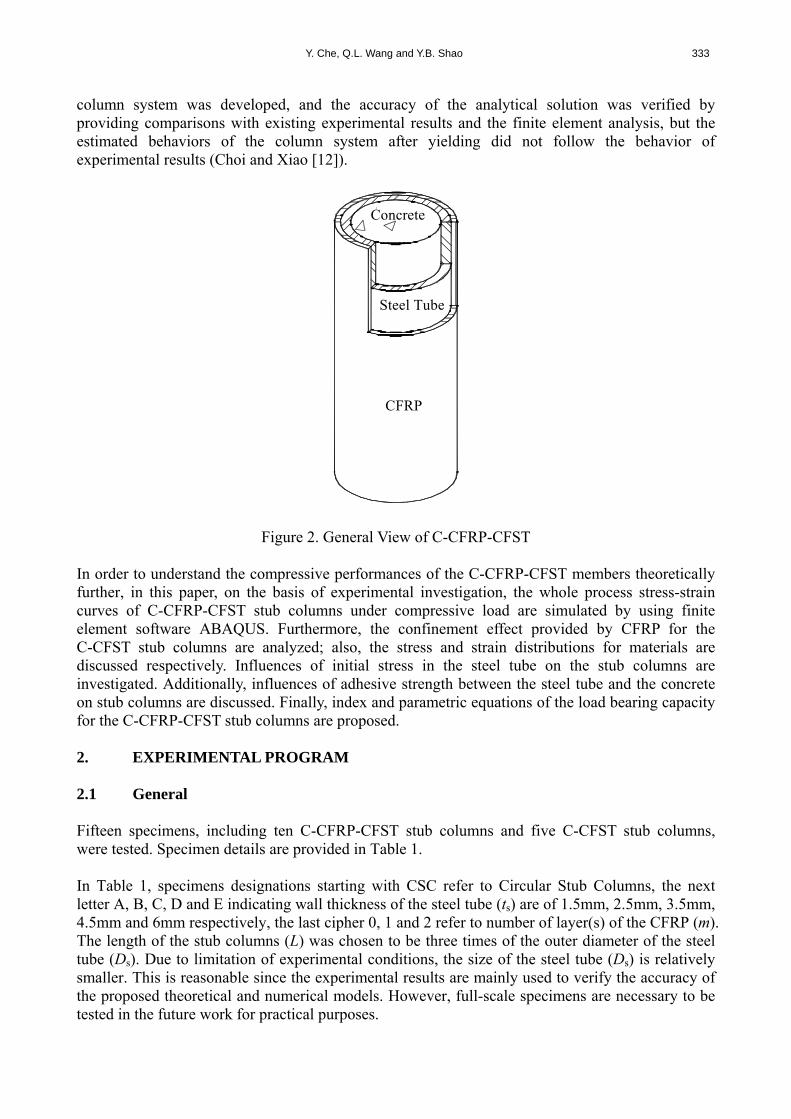
Y. Che, Q.L. Wang and Y.B. Shao 333
column system was developed, and the accuracy of the analytical solution was verified by providing comparisons with existing experimental results and the finite element analysis, but the estimated behaviors of the column system after yielding did not follow the behavior of experimental results (Choi and Xiao [12]).
Concrete
Steel Tube
CFRP
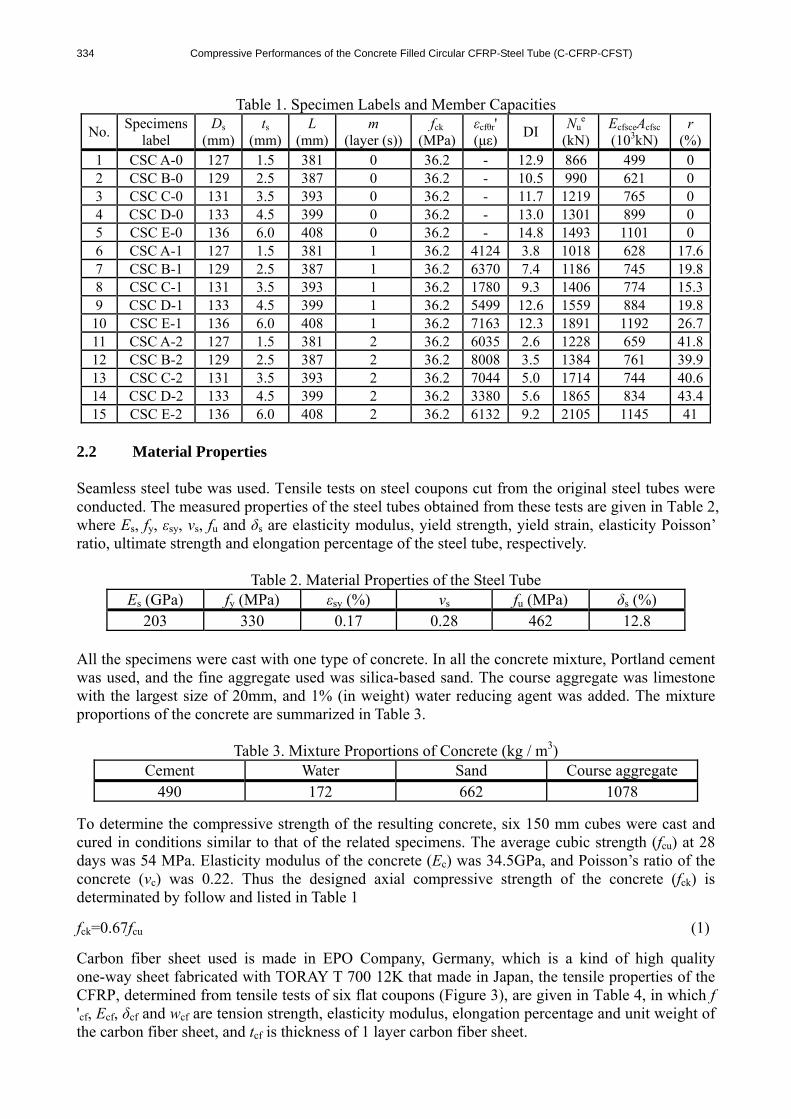
Figure 2. General View of C-CFRP-CFST In order to understand the compressive performances of the C-CFRP-CFST members theoretically further, in this paper, on the basis of experimental investigation, the whole process stress-strain curves of C-CFRP-CFST stub columns under compressive load are simulated by using finite element software ABAQUS. Furthermore, the confinement effect provided by CFRP for the C-CFST stub columns are analyzed; also, the stress and strain distributions for materials are discussed respectively. Influences of initial stress in the steel tube on the stub columns are investigated. Additionally, influences of adhesive strength between the steel tube and the concrete on stub columns are discussed. Finally, index and parametric equations of the load bearing capacity for the C-CFRP-CFST stub columns are proposed. 2. EXPERIMENTAL PROGRAM 2.1 General Fifteen specimens, including ten C-CFRP-CFST stub columns and five C-CFST stub columns, were tested. Specimen details are provided in Table 1. In Table 1, specimens designations starting with CSC refer to Circular Stub Columns, the next letter A, B, C, D and E indicating wall thickness of the steel tube (ts) are of 1.5mm, 2.5mm, 3.5mm, 4.5mm and 6mm respectively, the last cipher 0, 1 and 2 refer to number of layer(s) of the CFRP (m). The length of the stub columns (L) was chosen to be three times of the outer diameter of the steel tube (Ds). Due to limitation of experimental conditions, the size of the steel tube (Ds) is relatively smaller. This is reasonable since the experimental results are mainly used to verify the accuracy of the proposed theoretical and numerical models. However, full-scale specimens are necessary to be tested in the future work for practical purposes.
334 Compressive Performances of the Concrete Filled Circular CFRP-Steel Tube (C-CFRP-CFST)
Table 1. Specimen Labels and Member Capacities
No. Specimens
label Ds
(mm)ts
(mm) L
(mm)m
(layer (s)) fck
(MPa)εcfθr' (με)
DI Nu
e (kN)
EcfsceAcfsc (103kN)
r (%)
1 CSC A-0 127 1.5 381 0 36.2 - 12.9 866 499 0 2 CSC B-0 129 2.5 387 0 36.2 - 10.5 990 621 0 3 CSC C-0 131 3.5 393 0 36.2 - 11.7 1219 765 0 4 CSC D-0 133 4.5 399 0 36.2 - 13.0 1301 899 0 5 CSC E-0 136 6.0 408 0 36.2 - 14.8 1493 1101 0 6 CSC A-1 127 1.5 381 1 36.2 4124 3.8 1018 628 17.67 CSC B-1 129 2.5 387 1 36.2 6370 7.4 1186 745 19.88 CSC C-1 131 3.5 393 1 36.2 1780 9.3 1406 774 15.39 CSC D-1 133 4.5 399 1 36.2 5499 12.6 1559 884 19.8
10 CSC E-1 136 6.0 408 1 36.2 7163 12.3 1891 1192 26.711 CSC A-2 127 1.5 381 2 36.2 6035 2.6 1228 659 41.812 CSC B-2 129 2.5 387 2 36.2 8008 3.5 1384 761 39.913 CSC C-2 131 3.5 393 2 36.2 7044 5.0 1714 744 40.614 CSC D-2 133 4.5 399 2 36.2 3380 5.6 1865 834 43.415 CSC E-2 136 6.0 408 2 36.2 6132 9.2 2105 1145 41
2.2 Material Properties Seamless steel tube was used. Tensile tests on steel coupons cut from the original steel tubes were conducted. The measured properties of the steel tubes obtained from these tests are given in Table 2, where Es, fy, εsy, vs, fu and δs are elasticity modulus, yield strength, yield strain, elasticity Poisson’ ratio, ultimate strength and elongation percentage of the steel tube, respectively.
Table 2. Material Properties of the Steel Tube Es (GPa) fy (MPa) εsy (%) vs fu (MPa) δs (%)
203 330 0.17 0.28 462 12.8 All the specimens were cast with one type of concrete. In all the concrete mixture, Portland cement was used, and the fine aggregate used was silica-based sand. The course aggregate was limestone with the largest size of 20mm, and 1% (in weight) water reducing agent was added. The mixture proportions of the concrete are summarized in Table 3.
Table 3. Mixture Proportions of Concrete (kg / m3) Cement Water Sand Course aggregate
490 172 662 1078
To determine the compressive strength of the resulting concrete, six 150 mm cubes were cast and cured in conditions similar to that of the related specimens. The average cubic strength (fcu) at 28 days was 54 MPa. Elasticity modulus of the concrete (Ec) was 34.5GPa, and Poisson’s ratio of the concrete (vc) was 0.22. Thus the designed axial compressive strength of the concrete (fck) is determinated by follow and listed in Table 1
fck=0.67fcu (1)
Carbon fiber sheet used is made in EPO Company, Germany, which is a kind of high quality one-way sheet fabricated with TORAY T 700 12K that made in Japan, the tensile properties of the CFRP, determined from tensile tests of six flat coupons (Figure 3), are given in Table 4, in which f 'cf, Ecf, δcf and wcf are tension strength, elasticity modulus, elongation percentage and unit weight of the carbon fiber sheet, and tcf is thickness of 1 layer carbon fiber sheet.

Y. Che, Q.L. Wang and Y.B. Shao 335
Table 4. Main Technical Properties of the Carbon Fiber Sheets Model number f 'cf (GPa) Ecf (GPa) δcf (%) wcf (gm-2) tcf (mm)
C300/300 4.5 228 1.98 300 0.167 JGN-C, a kind of epoxy resin used for building structures that produced by Building Science Research Institute of Liaoning Province, P. R. China, was used for adhering the CFRP to the steel tube, another epoxy resin, JGN-P was adopted for gluing CFRPs together.
Figure 3. Typical Failed CFRP Coupon
2.3 Specimen Preparations In preparing the C-CFST specimens, the concrete was filled in layers and was vibrated by a poker vibrator. These specimens were then placed upright to air-dry until testing. Prior to testing, the top surfaces of the C-CFST specimens were ground smooth and flat, using a grinding wheel. A steel plate with a thickness of 20 mm was then welded to the top of each of the specimens. Carbon fiber sheets were applied using a hand lay-up method. The finishing end of a sheet overlapped the starting end by 150 mm. 2.4 Test Setup and Instrumentation A 5000 kN capacity testing machine was used for the compression tests on all specimens. Eight strain gauges, including four in the longitudinal direction and another four in the circumferential direction, mounted on the steel tube surface of each specimen, were used to measure longitudinal strain of the steel tube (εsl) and circumferential strain of the steel tube (εsθ) at the mid-height cross-section, respectively. Also, four strain gauges in the circumferential direction, mounted on the CFRP surface of each specimen, were used to measure circumferential strain of the CFRP (εcfθ) at the mid-height cross-section. Two Linear Variable Displacement Transducers (LVDTs) were used to measure axial shortening of the specimens (Δ) during the tests. UCAM70A was used for data logging. Test arrangement is shown in Figure 4. To assure uniform compression, preliminary tests within the elastic range were conducted by carefully adjusting the position of the specimen, based on the measurements of the strain gauges attached at the mid-height cross-section of the test specimen. The adjustment was terminated when the difference between the measured strain and the average value was no more than 5%. A load interval of less than one tenth of the estimated load capacity was used. Each load interval was maintained for about 2 to 3 min.
336 Compressive Performances of the Concrete Filled Circular CFRP-Steel Tube (C-CFRP-CFST)
Loading Ram
Loading Ram
LVDTLVDT
Str
ain
Gau
ges
Spe
cim
en
Figure 4. Test Arrangement
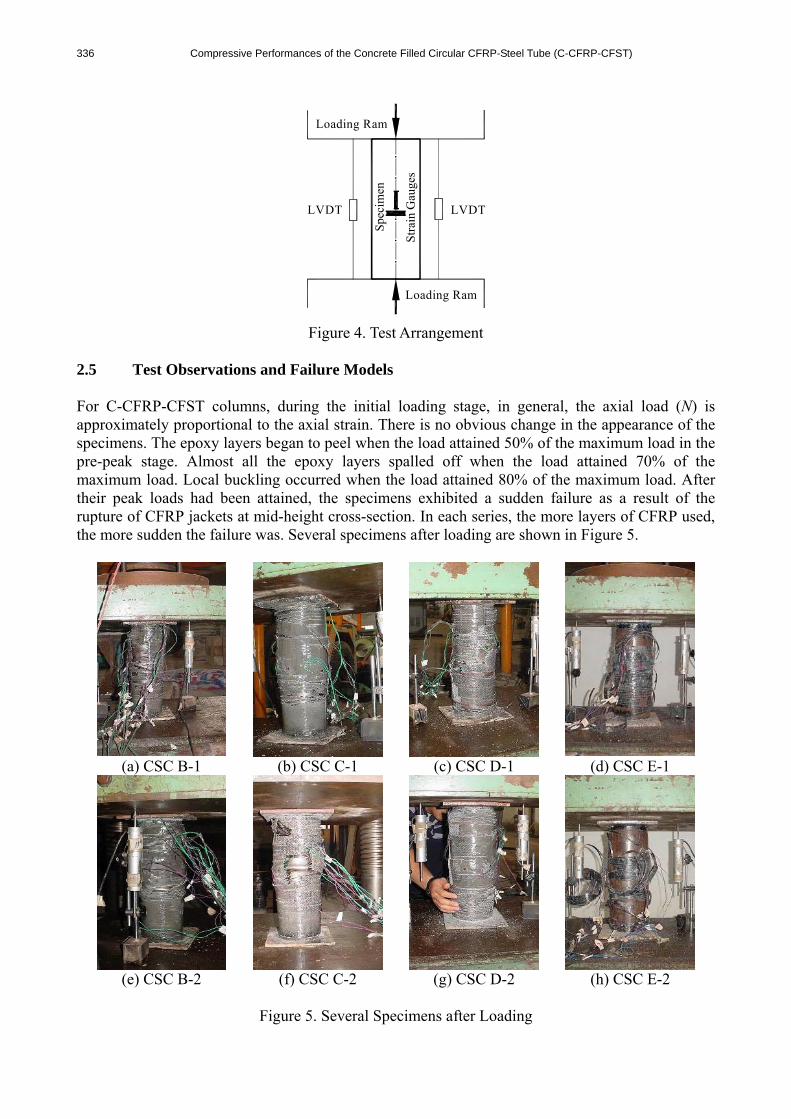
2.5 Test Observations and Failure Models For C-CFRP-CFST columns, during the initial loading stage, in general, the axial load (N) is approximately proportional to the axial strain. There is no obvious change in the appearance of the specimens. The epoxy layers began to peel when the load attained 50% of the maximum load in the pre-peak stage. Almost all the epoxy layers spalled off when the load attained 70% of the maximum load. Local buckling occurred when the load attained 80% of the maximum load. After their peak loads had been attained, the specimens exhibited a sudden failure as a result of the rupture of CFRP jackets at mid-height cross-section. In each series, the more layers of CFRP used, the more sudden the failure was. Several specimens after loading are shown in Figure 5.
(a) CSC B-1 (b) CSC C-1 (c) CSC D-1 (d) CSC E-1
(e) CSC B-2 (f) CSC C-2 (g) CSC D-2 (h) CSC E-2
Figure 5. Several Specimens after Loading
Y. Che, Q.L. Wang and Y.B. Shao 337
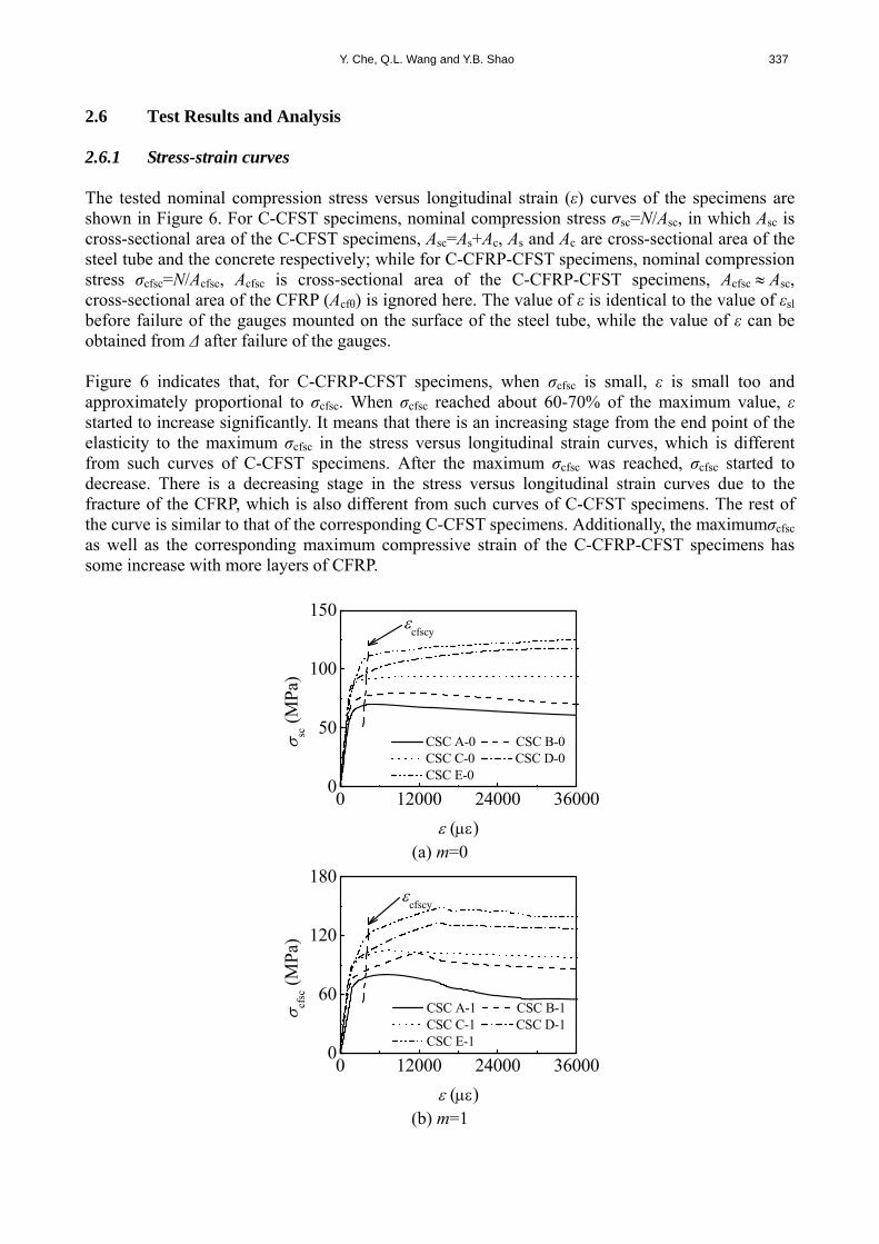
2.6 Test Results and Analysis 2.6.1 Stress-strain curves The tested nominal compression stress versus longitudinal strain (ε) curves of the specimens are shown in Figure 6. For C-CFST specimens, nominal compression stress σsc=N/Asc, in which Asc is cross-sectional area of the C-CFST specimens, Asc=As+Ac, As and Ac are cross-sectional area of the steel tube and the concrete respectively; while for C-CFRP-CFST specimens, nominal compression stress σcfsc=N/Acfsc, Acfsc is cross-sectional area of the C-CFRP-CFST specimens, Acfsc Asc, cross-sectional area of the CFRP (Acfθ) is ignored here. The value of ε is identical to the value of εsl before failure of the gauges mounted on the surface of the steel tube, while the value of ε can be obtained from Δ after failure of the gauges. Figure 6 indicates that, for C-CFRP-CFST specimens, when σcfsc is small, ε is small too and approximately proportional to σcfsc. When σcfsc reached about 60-70% of the maximum value, ε started to increase significantly. It means that there is an increasing stage from the end point of the elasticity to the maximum σcfsc in the stress versus longitudinal strain curves, which is different from such curves of C-CFST specimens. After the maximum σcfsc was reached, σcfsc started to decrease. There is a decreasing stage in the stress versus longitudinal strain curves due to the fracture of the CFRP, which is also different from such curves of C-CFST specimens. The rest of the curve is similar to that of the corresponding C-CFST specimens. Additionally, the maximumσcfsc as well as the corresponding maximum compressive strain of the C-CFRP-CFST specimens has some increase with more layers of CFRP.
0
50
100
150
0 12000 24000 36000
cfscy
()
sc (
MPa
)
CSC A-0 CSC B-0 CSC C-0 CSC D-0 CSC E-0
(a) m=0
0
60
120
180
0 12000 24000 36000
cfscy
()
cfsc
(M
Pa)
CSC A-1 CSC B-1 CSC C-1 CSC D-1 CSC E-1
(b) m=1

338 Compressive Performances of the Concrete Filled Circular CFRP-Steel Tube (C-CFRP-CFST)
0
70
140
210
0 12000 24000 36000
cfscy
()
cfsc
(M
Pa)
CSC A-2 CSC B-2 CSC C-2 CSC D-2 CSC E-2
(c) m=2
Figure 6. Tested Nominal Compression Stress versus Longitudinal Strain Curves of the Specimens
2.6.2 Cooperation between steel tube and CFRP Figure 7 illustrates the tested axial load (N) versus circumferential strain (εθ) curves for C-CFRP-CFST stub columns. It can be seen from Figure 7 that εsθ and εcfθ are the same approximately from initial stage of loading till the CFRP rupturing, and it means that wrapping CFRP in accordance with the procedure used in this paper would ensure the steel tube and the CFRP work concurrently before failure.
0
800
1600
2400
0 -4000 -8000 -12000
cf
of CSC A-1
cf
of CSC B-1
cf
of CSC C-1
cf
of CSC D-1
cf
of CSC E-1
()
N (
kN)
s
of CSC A-1
s
of CSC B-1
s
of CSC C-1
s
of CSC D-1
s
of CSC E-1
(a) m=1

Y. Che, Q.L. Wang and Y.B. Shao 339
0
900
1800
2700
0 -4000 -8000 -12000
cf
of CSC A-2
cf
of CSC B-2
cf
of CSC C-2
cf
of CSC D-2
cf
of CSC E-2
()
N (
kN)
s
of CSC A-2
s
of CSC B-2
s
of CSC C-2
s
of CSC D-2
s
of CSC E-2
(b) m=2
Figure 7. N versus εθ Curves for C-CFRP-CFST Stub Columns
2.6.3 Ductility In order to quantify the effect of CFRP jackets on section ductility, a ductility index (DI) (Tao, Han and Wang [13]) is used: DI=ε85%/εy (2) εy=ε75%/0.75 (3) where ε85% is the longitudinal strain when the load falls to 85% of the maximum load, and ε75% is the longitudinal strain when the load attains 75% of the maximum load in the pre-peak stage. The ductility indices are given in Table 1 and plotted in Figure 8 for all specimens, where ξcf is confinement factor of the CFRP (Wang, Guan and zhao [7]) ξcf=Acfθfcfθ/(Acfck) (4) in which fcfθ is the ultimate tensile strength of the CFRP, and fcfθ=Ecfεcfθr (5) where εcfθr (=5500με) is the average value of the fracture strains (εcfθr') of CFRP on all C-CFRP-CFST specimens, εcfθr' is obtained from the strain gauges glued on the CFPR of all the C-CFRP-CFST specimens and listed in Table 1. It should be noted that rupture strain value of the CFRP mounted on the specimens is not the same as that of coupon tests as listed in Table 4 (δcf=1.98%, 19800με), this deviation is perhaps due to the different curvature of the CFRPs (Yu et al. [14]), and the real reason should be investigated in the future. εcfθr was used later for finite element modelling and calculation of the load bearing capacity.

340 Compressive Performances of the Concrete Filled Circular CFRP-Steel Tube (C-CFRP-CFST)
It can be seen from Figure 8 that the ductility of the C-CFRP-CFST specimens generally decreases with the increasing of confinement factor of the CFRP. This can be attributed to the abrupt rupture of CFRP jackets. The more layers of CFRP jacket used, the more abrupt the failure.
-0.15 0.00 0.15 0.30 0.45 0.600
8
16
24
DI
cf
ts=1.5mm t
s=2.5mm
ts=3.5mm t
s=4.5mm
ts=6.0mm
Figure 8. Ductility Index
3. FE SIMULATION 3.1 Stress-Strain Relationship of the Materials 3.1.1 Steel A 5-stages stress-strain relationship of steel (Han, Yao and Tao [15]) is used here. 3.1.2 Concrete For concrete confined by circular CFRP-steel tube under compression, stress-strain property is given based on experimental investigation as well as considering corresponding reported research about concrete confined by circular steel tube under compression (Wang, Zhu and Gao [16]) as follow
ucl
0cl2
0cls
0cl
ucl0s
0cl2
0cl
10cl
s0cl1.0
0cl
0cl2
0cl0cl
0cl
1
12.11
12.11
2
D
Cqq (6)
Where σcl is longitudinal stress of the concrete; σ0 is the ultimate compressive stress of the concrete, εcl is longitudinal strain of the concrete and ε0 is the ultimate compressive strain of the concrete. q is a quantity related to total confinement factor ξ (Wang, Guan and zhao [7]); C and D are all coefficients; β is a quantity related to ξ before fracture of the CFRP; βs is a quantity related to ξs; ξs is confinement factor of the steel tube (Han, Yao and Tao [15]); εu is the longitudinal strain of the specimen (ε) when CFRP is fractured, and σ0=f 'c(MPa) (7) ε0=εcc+(600+32.4f 'c)ξ
0.2×10⁻⁶ (8)

Y. Che, Q.L. Wang and Y.B. Shao 341
εcc=(1300+12.09f 'c)×10-6 (9)
q=ξ0.745/(2+ξ) (10) ξ=ξs+ξcf (11) C=ξ '(2.231-4.611ξ ') (12) D=ξ '(1.545-1.238ξ ') (13)
42c
5.025.05 10'1036.228.37
f
(14)
42c
5.025.05s 10'1036.25.0
7s f (15)
ξs=Asfy/(Acfck) (16) εu=ε0+51659ξcf-38904ξcf
2 (17) in above equations, f 'c is compressive strength of the circular concrete specimens, and its relationship with fcu, can be found in relative literature (Tao, Han and Wang [13]); ξ ' is confinement factor ratio (Wang, Guan and Zhao [7]), and ξ '=ξcf/ξs (18) The softening property for concrete under tensile stress is simulated by energy criterion, as shown in Figure 9. In Figure 9, w is concrete crack width; w1 is the maximum crack width; σt is tensile stress of the concrete; Gf is rupture energy of the concrete (for f 'c=20MPa, Gf is of 40N/m, for f 'c=40MPa, Gf is of 120N/m, and for other value of f 'c between 20 MPa and 40 MPa, the value of Gf can be obtained by using interpolation method); σt0 is the ultimate tension stress of the concrete. σt0=0.26(1.5fck)
2/3 (19)
0
150
300
450
0.00 0.03 0.06 0.09
Gf=
t0w
1/2
w 1
t0
w
t
Figure 9. Constitutive Relationship of the Tensile Concrete

342 Compressive Performances of the Concrete Filled Circular CFRP-Steel Tube (C-CFRP-CFST)
3.1.3 CFRP The CFRP is assumed to be subjected to circular tension, and the stress value in other direction is assumed to be 0.001MPa. Before fracture, the stress-strain relationship is in accordance with Hooke’s Law cf=Ecfcf (20) where σcfθ is circumferential stress of the CFRP. 3.2 FE Model 3.2.1 Element type selection The element of the steel tube adopts shell element S4 with full integration. To satisfy the computing accuracy, Simpson integration with 9 integrating points in the shell thickness direction is used. For the concrete, 3-D brick elements C3D8R with reduced integration are used for modeling. Membrane element M3D4 with four nodes is used for modeling the CFRP. 3.2.2 Mesh discritization The convergent analysis is carried out by using refined mesh in FE analysis. In this scheme, an original relative coarse mesh is used to conduct FE analysis, and then the mesh is doubled to carry out FE analysis again to assess the convergence of the numerical results. If the FE results with original and refined meshes converge, i.e., the relative error is less than 1%, the original mesh is suitable for numerical analysis. Otherwise, the mesh will be refined again to conduct additional analysis till the convergence of the FE results is satisfied. Figure 10 is the view of the FE mesh.
(a) Transverse Element (b) Longitudinal Element
Figure 10. Mesh Discritization 3.2.3 Interface model Hard contact is used for contact interface between the steel tube and the concrete, i.e., the pressure perpendicular to the contact surfaces (p) can be transferred completely between the two surfaces (Han, Liu and Yang [17]). The tangential force between the steel tube and the concrete surfaces is simulated by using Columb model, i.e., shear force can be transferred between surfaces (Han, Liu and Yang [17]). According to the test results, the CFRP is bound to steel tube, and it is assumed no slip exists between CFRP and steel tube. Same nodal freedoms are used for the contact elements between CFRP and steel tube. When CFRP reaches its ultimate strength and is fractured, CFRP loses its confinement to the steel tube. In the tangential direction of the contact surfaces between

Y. Che, Q.L. Wang and Y.B. Shao 343
the end plate and the concrete, there is no slipping, and hard contact assumption is used in normal direction of contact surfaces. 3.2.4 Boundary conditions Only the axial freedom at the load applied end is released, and all the freedoms at the other end are fixed. The displacement is applied along the axis of the columns. To avoid the deformation of the end plate and to model the boundary condition more accurately, the stiffness of the end plate is set to be very large in the FE analysis. The elastic modulus and Poisson’s ratio are 1012 MPa and 0.0001, respectively. 3.3 FE Results and Parametric Analysis 3.3.1 FE results To verify the reliability of the above presented FE method, overall 10 C-CFRP-CFST specimens are analyzed by using ABAQUS software. The FEM results together with the tested measured results are plotted in Figure 11. It can be found from Figure 11 that the FEM results agree reasonably well with the experimental results.
0 12000 24000 360000
450
900
1350
N (
kN)
()
Tested result FEM result
0 12000 24000 360000
500
1000
1500
N (
kN)
()
Tested result FEM result
(a) CSC A-1 (b) CSC A-2
0 12000 24000 360000
500
1000
1500
N (
kN)
()
Tested result FEM result
0 12000 24000 360000
600
1200
1800
N (
kN)
()
Tested result FEM result
(c) CSC B-1 (d) CSC B-2

344 Compressive Performances of the Concrete Filled Circular CFRP-Steel Tube (C-CFRP-CFST)
0 12000 24000 360000
550
1100
1650N
(kN
)
()
Tested result FEM result
0 12000 24000 360000
600
1200
1800
N (
kN)
()
Tested result FEM result
(e) CSC C-1 (f) CSC C-2
0 12000 24000 360000
650
1300
1950
N (
kN)
()
Tested result FEM result
0 12000 24000 360000
700
1400
2100
N (
kN)
()
Tested result FEM result
(g) CSC D-1 (h) CSC D-2
0 12000 24000 360000
750
1500
2250
N (
kN)
()
Tested result FEM result
0 12000 24000 360000
800
1600
2400
N (
kN)
()
Tested result FEM result
(i) CSC E-1 (j) CSC E-2
Figure 11. Comparison between FEM Results and Tested Results of N-ε Curves
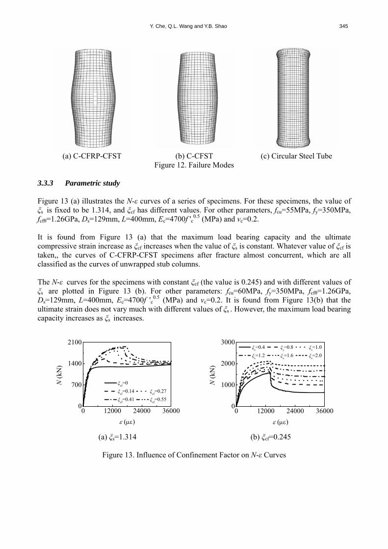
of the C-CFRP-CFST Stub Columns 3.3.2 Failure modes Figure 12 (a) shows failure mode of the C-CFRP-CFST stub column. For comparing purpose, failure modes of the C-CFST stub column and circular steel tubular stub column are also given, and they are shown in Figure 12 (b) and 12 (c), respectively. It can be seen from Figure 12 (c) that local buckling occurs at both ends of the circular steel tubular stub column. For C-CFST stub column, it convexes at the mid-height cross-section. Similarly, C-CFRP-CFST stub column also convexes at the mid-height cross-section. However, its deformation is relatively smaller due to the confinement of the un-fractured CFRP.
Y. Che, Q.L. Wang and Y.B. Shao 345
(a) C-CFRP-CFST (b) C-CFST (c) Circular Steel Tube
Figure 12. Failure Modes 3.3.3 Parametric study Figure 13 (a) illustrates the N-ε curves of a series of specimens. For these specimens, the value of ξs is fixed to be 1.314, and ξcf has different values. For other parameters, fcu=55MPa, fy=350MPa, fcfθ=1.26GPa, Ds=129mm, L=400mm, Ec=4700f 'c
0.5 (MPa) and vc=0.2. It is found from Figure 13 (a) that the maximum load bearing capacity and the ultimate compressive strain increase as ξcf increases when the value of ξs is constant. Whatever value of ξcf is taken,, the curves of C-CFRP-CFST specimens after fracture almost concurrent, which are all classified as the curves of unwrapped stub columns. The N-ε curves for the specimens with constant ξcf (the value is 0.245) and with different values of ξs are plotted in Figure 13 (b). For other parameters: fcu=60MPa, fy=350MPa, fcfθ=1.26GPa, Ds=129mm, L=400mm, Ec=4700f 'c
0.5 (MPa) and vc=0.2. It is found from Figure 13(b) that the ultimate strain does not vary much with different values of ξs . However, the maximum load bearing capacity increases as ξs increases.
0 12000 24000 360000
700
1400
2100
N (
kN)
()
cf=0
cf=0.14
cf=0.27
cf=0.41
cf=0.55
0 12000 24000 360000
1000
2000
3000
N (
kN)
()
s=0.4
s=0.8
s=1.0
s=1.2
s=1.6
s=2.0
(a) ξs=1.314 (b) ξcf=0.245
Figure 13. Influence of Confinement Factor on N-ε Curves

346 Compressive Performances of the Concrete Filled Circular CFRP-Steel Tube (C-CFRP-CFST)
4. FURTHER ANALYSIS The details of the typical model are listed as follows: L=1200mm, Ds=400mm, ts=9.3mm, fy=345MPa, ξcf=0.191, ξs=0.857, fcu=60MPa, Ec=4700f 'c
0.5 (MPa) and vc=0.2. 4.1 Stress-Strain Curves Figure 14 gives stress (σ)-strain curves of the C-CFST stub columns under axial compression. For a clear expression, longitudinal stress of the steel tube (σsl) is divided by 10, and the confinement force (p) is multiplied by 5. It can be found from Figure 14 that the confinement force in the initial stage (ε<800με) is negative. This means there is minor tensile stress on the steel and the concrete interface because Poisson’s ratio of the steel is bigger than that of the concrete at this time, and the steel and the concrete have an apart tendency.
0 6000 12000 18000-50
0
50
100
150
Fig. 14 (b)
(M
Pa)
()
sc
cl
sl/10 5p
0 600 1200 1800-5
0
5
10
15
(M
Pa)
()
sc
cl
sl/10 5p
(a) Full View (b) Magnified Part
Figure 14. σ versus ε Curves of the C-CFST Stub Columns Figure 15 shows stress-strain curves of the C-CFRP-CFST stub columns under axial compression. Similarly, longitudinal stress of the steel and circular stress of the CFRP are also divided by 10, and the confinement force is multiplied by 5. As shown in Figure 15, the steel tube always provides positive confinement force to the concrete for C-CFRP-CFST stub columns due to the existence of CFRP. In elasto-plastic stage, steel begins to yield before the stub columns reach the ultimate tensile strength. At this time, the confinement force between the steel tube and the concrete is increasing steadily. When CFRP reaches its ultimate tensile strength and is fractured, the stress-strain curve of the concrete has steep decreasing segment and then it becomes gradual. Meanwhile, the confinement force of outer tube begins to decrease because CFRP does not work now, and only steel tube provides confinement to the concrete. Before fracture, CFRP is always in linear and elastic stage. However, the stresses in CFRP reduce to zero rapidly after fracture.
0 6000 12000 18000-60
0
60
120
180
Fig. 15 (b)
(M
Pa)
()
cfsc
cl
sl/10
cf
/10 5p
0 600 1200 1800-6
0
6
12
18
(M
Pa)
()
cfsc
cl
sl/10
cf
/10
5p
(a) Full View (b) Magnified Part
Figure 15. σ versus ε Curves of the C-CFRP-CFST Stub Columns

Y. Che, Q.L. Wang and Y.B. Shao 347
Additionally, the elasto-plastic stage of C-CFRP-CFST stub columns is longer than that of C-CFST stub columns due to the confinement of CFRP to the tube. The maximum load bearing capacity also increases, and the stress decreasing stage of the concrete is much different due to the existence of the CFRP. 4.2 Stress Analysis Distribution of σcl on the mid-height cross-section of the C-CFRP-CFST stub columns is shown in Figure 16. Point 1 is the yield point of steel tube, and the specimen reaches its maximum load bearing capacity at point 2, the strain at point 3 is 20000ε. From Figure 16, it can be found that the longitudinal stresses of concrete on mid-height cross-section are almost uniform when steel tube becomes yielding, and the value is about f 'c. Before reaching the maximum load bearing capacity, the longitudinal stress in concrete is the maximum, and the value is about 2f 'c. The stress values become smaller when the distance from the center is bigger. When the strain is equal to 20000ε, the longitudinal stress at the centroid of concrete has a little drop and the stresses of outer concrete also decrease. However, the stresses along circular direction always keep uniformly.
0 12000 24000 360000
45
90
135
Point 1 Point 2 Point 3
(a) σ-ε Curve (b) Point 1
(c) Point 2 (d) Point 3
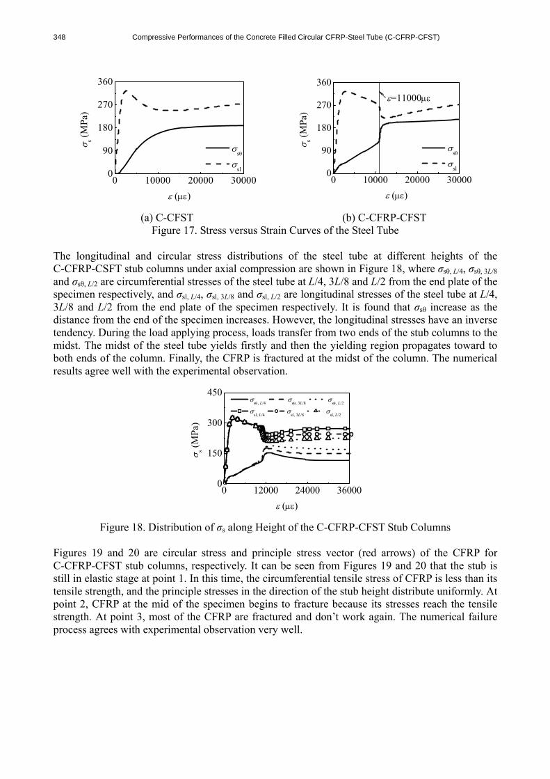
Figure 16. Distribution of σcl on Mid-height Cross-section of the C-CFRP-CFST Stub Columns The variations of the steel tube stresses in longitudinal direction (σsl) and in circular direction (σsθ) on the mid-height cross-section of C-CFST stub columns and C-CFRP-CFST stub columns under compression are plotted together in Figures 17 (a) and 17 (b), where σs is stress of the steel tube. It is noted that Figures 17 (a) and 17 (b) only provide the stress magnitude and ignore the stress sign. It can be seen from Figure 17 that the variation of σs of the C-CFRP-CFST stub columns under axial compression is much similar with that of the C-CFST stub columns before the fracture of CFRP whereas the circular stress of the steel tube increases rapidly and the longitudinal stress decreases sharply due to rupture of the CFRP.
348 Compressive Performances of the Concrete Filled Circular CFRP-Steel Tube (C-CFRP-CFST)
0 10000 20000 300000
90
180
270
360 s (
MPa
)
()
s
sl
0 10000 20000 300000
90
180
270
360
=11000
s (M
Pa)
()
s
sl
(a) C-CFST (b) C-CFRP-CFST
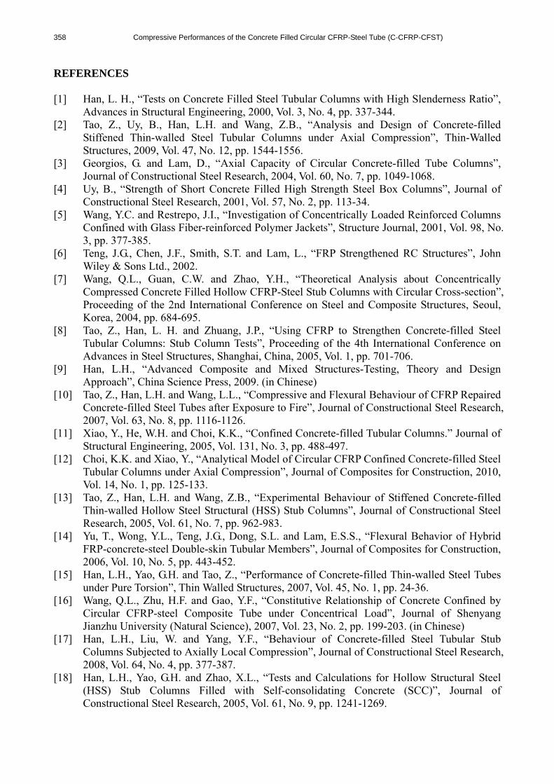
Figure 17. Stress versus Strain Curves of the Steel Tube The longitudinal and circular stress distributions of the steel tube at different heights of the C-CFRP-CSFT stub columns under axial compression are shown in Figure 18, where σsθ, L/4, σsθ, 3L/8 and σsθ, L/2 are circumferential stresses of the steel tube at L/4, 3L/8 and L/2 from the end plate of the specimen respectively, and σsl, L/4, σsl, 3L/8 and σsl, L/2 are longitudinal stresses of the steel tube at L/4, 3L/8 and L/2 from the end plate of the specimen respectively. It is found that σsθ increase as the distance from the end of the specimen increases. However, the longitudinal stresses have an inverse tendency. During the load applying process, loads transfer from two ends of the stub columns to the midst. The midst of the steel tube yields firstly and then the yielding region propagates toward to both ends of the column. Finally, the CFRP is fractured at the midst of the column. The numerical results agree well with the experimental observation.
0 12000 24000 360000
150
300
450
s (M
Pa)
()
s, L/4
s, 3L/8
s, L/2
sl, L/4
sl, 3L/8
sl, L/2
Figure 18. Distribution of σs along Height of the C-CFRP-CFST Stub Columns
Figures 19 and 20 are circular stress and principle stress vector (red arrows) of the CFRP for C-CFRP-CFST stub columns, respectively. It can be seen from Figures 19 and 20 that the stub is still in elastic stage at point 1. In this time, the circumferential tensile stress of CFRP is less than its tensile strength, and the principle stresses in the direction of the stub height distribute uniformly. At point 2, CFRP at the mid of the specimen begins to fracture because its stresses reach the tensile strength. At point 3, most of the CFRP are fractured and don’t work again. The numerical failure process agrees with experimental observation very well.

Y. Che, Q.L. Wang and Y.B. Shao 349
(a) Point 1 (b) Point 2 (c) Point 3
Figure 19. σcfθ of the C-CFRP-CFST Stub Columns
(a) Point 1 (b) Point 2 (c) Point 3
Figure 20. Principle Stress Vector of CFRP of the C-CFRP-CFST Stub Columns 4.3 Strain Analysis The longitudinal stress-strain relationships for C-CFRP-CFST (fcu=60MPa, fy=350 MPa, fcfθ=1.26GPa, Ds=129mm, L=400mm, Ec=4700f 'c
0.5 (MPa) and vc=0.2) with same CFRP confinement factors and different steel tube confinement factors are studied. Similarly, such relationships for C-CFRP-CFST (fcu=60MPa, fy=350MPa, fcfθ=1.26GPa, Ds=133mm, L=400mm, Ec=4700f 'c
0.5 (MPa) and vc=0.2) with same steel tube confinement factors and different CFRP confinement factors are also investigated. These results are illustrated in Figures 21 (a) and 21 (b) respectively. As shown in Figure 21, the peak stress of concrete increases as ξs becomes bigger and ξcf is kept constant. However, the variation of the peak stress value is not very remarkable. When ξs is kept constant and ξcf becomes bigger, the peak stress and strain both increase. Figure 22 and Figure 23 are distributions of circular strains of the steel tube for C-CFST stub columns and C-CFRP-CFST stub columns, respectively. Comparing the results in Figures 22 and 23, it is found that CFRP is in elastic stage at point 1, and the CFRP can still provide confinement to the steel tube. Therefore, the circumferential strains of the steel tube of C-CFRP-CFST are a little smaller than those of C-CFST. At point 2, the circumferential strains of the steel tube are much smaller than those of C-CFST, and this means CFRP has remarkable confinement to the steel tube in circumferential direction at this time. At point 3, the CFRP at the mid of the C-CFRP-CFST is fractured, and thus it loses the confinement to the steel tube. Based on the above reasons, the circumferential strains of the steel tube for the two specimens are almost the same.

350 Compressive Performances of the Concrete Filled Circular CFRP-Steel Tube (C-CFRP-CFST)
0 12000 24000 360000
60
120
180 cl
(M
Pa)
cl ()
s=0.4
s=0.8
s=1.0
s=1.2
s=1.6
s=2.0
0 12000 24000 360000
50
100
150
cl (
MP
a)
cl ()
cf=0
cf=0.12
cf=0.24
cf=0.36
cf=0.48
(a) ξcf=0.132 (b) ξs=1.3
Figure 21. Longitudinal Stress versus Strain Curves of the Concrete for C-CFRP-CFST Stub Column
(a) Point 1 (b) Point 2 (c) Point 3
Figure 22. εsθ of the C-CFST Stub Columns
(a) Point 1 (b) Point 2 (c) Point 3
Figure 23. εsθ of the C-CFRP-CFST Stub Columns 4.4 Effect of Initial Stress in the Steel Tube on Properties of the Columns Figure 24 shows load-strain curves of the C-CFRP-CFST stub columns under axial compression with different initial stress coefficients (β0), and β0=σs0/(sfy) (21) where σs0 is initial stress in the steel tube, and s is stability coefficient of the circular steel tube.

Y. Che, Q.L. Wang and Y.B. Shao 351
As shown in Figure 24, the initial stress in the steel tube can reduce the stiffness in elastic stage of the C-CFRP-CFST stub columns under axial compression, and the load bearing capacity decreases as the initial stress coefficient increases. A series of p-ε curves for C-CFRP-CFST stub columns under axial compression with different initial stress coefficients are plotted in Figure 25. The initial stress in the steel tube produces initial compressive strain in the steel tube before the steel tube and the concrete are subjected to loading jointly, which can postpone the mutual reaction between the steel tube and the concrete. Generally, the initial stress of steel tube has a little influence on the peak value of the confinement force.
0 12000 24000 360000
6000
12000
18000
N (
kN)
()
0=0
0=0.2
0=0.4
0=0.6
0=0.8
Figure 24. Influence of σs0 on N-ε Curves of the C-CFRP-CFST Stub Columns
0 12000 24000 360000
4
8
12
p (M
Pa)
()
0=0
0=0.2
0=0.4
0=0.6
0=0.8
Figure 25. Influence of σs0 on p-ε Curves of the C-CFRP-CFST Stub Columns
Figure 26 shows the longitudinal stress distribution on the cross-section of the column midst before ultimate state for the C-CFRP-CFST stub columns under axial compression with different initial stress coefficients of the steel tube. It can be seen from Figure 26 that the initial stress in the steel tube has very little effect on the longitudinal stress distribution on the mid-height cross-section of the concrete before the specimen reaches the ultimate state, and the longitudinal stress values decrease as the initial stress coefficients become bigger.

352 Compressive Performances of the Concrete Filled Circular CFRP-Steel Tube (C-CFRP-CFST)
(a) β0=0 (b) β0=0.2
(c) β0=0.4 (d) β0=0.6 (e) β0=0.8
Figure 26. Influence of σs0 on Longitudinal Stress Distribution of the Concrete at Mid-height
Cross-section for C-CFRP-CFST Stub Columns 4.4 Effect of Adhesive Strength on Properties of the Columns Three friction factors with values of 0, 0.3 and 0.6 are used to model the different adhesive strength between steel tube and the concrete. Figure 27 shows the influence of adhesive strength on N-ε curves of the C-CFRP-CFST stub columns. As shown in Figure 27, the effect of adhesive strength on the N-ε curves is very little.
0 12000 24000 360000
6000
12000
18000
N (
kN)
()
=0 =0.3 =0.6
Figure 27. Influence of Adhesive Strength on N-ε Curves of the C-CFRP-CFST Stub Columns

Y. Che, Q.L. Wang and Y.B. Shao 353
5. LOAD BEARING CAPACITY INDEX 5.1 Expression The stress-strain relationship of the C-CFRP-CFST stub column is investigated based on the FE analysis of many models. The validity range of these models is: fy=200-400MPa, fu=30-120MPa, ξs=0.2-4, ξcf=0-0.6. Finally, the load bearing capacity at the longitudinal strain εcfscy (Figure 6) which is determined from the stress-strain curves is defined as the load bearing capacity index of axial compressive strength (fcfscy). εcfscy is expressed as follow εcfscy=1300+12.5 f 'c +(600+33.3 f 'c)ξ
0.2 (με) (22) The relationship between γc (=fcfscy/fck) and (ξs+3ξcf) can be expressed with simple equation as shown in Figure 28 (a). The equation is obtained from regression analysis and fcfscy is listed as follow fcfscy=[1.14+1.02(ξs+3ξcf)]fck (23) The load bearing capacity (Nu) of the C-CFRP-CFST stub column under axial compression can be calculated by using the following equation Nu=Acfscfcfscy (24) In case of no CFRP (C-CFST), Eqs. (22)-(24) are reduced to the corresponding calculating equations of the C-CFST stub columns (Han, Yao and Zhao [18]). Figure 28 (b) shows the comparison of the estimated results of Nu (Nu
c) and the experimental results of Nu (Nu
e) for the stub columns. It is found that the simplified equation can produce reasonably accurate estimations. The average of Nu
c/Nue is 0.902 and the mean square deviation is 0.0536. In
general, the predicted results from the equation are safe.
0.0 1.4 2.8 4.20
2
4
6
c=1.14+1.02(
s+3
cf)
c
s+3
cf
fy=235MPa
fy=345MPa
fy=390MPa
0 800 1600 24000
800
1600
2400
m=0 m=1 m=2
Nu
e=Nu
c
Nuc (
kN)
Nu
e (kN)
(a) Curve-fitting Expression (b) Comparison between Predicted Results
and Tested Results for Nu Figure 28. Load Bearing Capacity Index

354 Compressive Performances of the Concrete Filled Circular CFRP-Steel Tube (C-CFRP-CFST)
5.2 Load Bearing Capacity Increment Ratio For specimens with the same ts, named Nu
e of C-CFST as Nu0e, and that of C-CFRP-CFST as Num
e, then r is load bearing capacity increment ratio, r=(Num
e-Nu0e)/Nu0
e×100% (25) r are listed in Table 1 and plotted against ξcf in Figure 29. Figure 29 shows that comparing with the C-CFST stub columns, Num
e are all enhanved, and r increases nearly linearly with the increment of m.
0 1 20
16
32
48r
(%)
m (layer(s))
ts=1.5mm t
s=2.5mm
ts=3.5mm t
s=4.5mm
ts=6.0mm
Figure 29. Influence of m on Load Bearing Capacity Increment Ratio (r)
5.3 Stiffness Referring to corresponding study (Han, Yao and Zhao [18]), it is found from computation that the following equation can be used to calculate the longitudinal stiffness (EcfsceAcfsc) of the C-CFRP-CFST stub columns Ecfsce=fcfscp/εcfscp (26) fcfscp=[0.192/(1-0.6ξcf)
2(fy/235)+0.488(1-2.4ξcf)]fcfscy (27) εcfscp=3.25×10⁻⁶fy (28) where fcfscp is nominal proportional limit of the C-CFRP-CFST stub columns, and εcfscp is the corresponding strain at the nominal proportional limit. Eqs. (26)-(28) are also suitable for C-CFST stub columns (ξcf=0). The EcfsceAcfsc of the tested specimens are tabulated in Table 1 and shown in Figure 30. As can be seen that the specimens exhibited an increase in their stiffness after being wrapped with CFRP and their stiffness increased with the increasing number of m.

Y. Che, Q.L. Wang and Y.B. Shao 355
0 1 20
800
1600
2400
Ecf
sceA
cfsc
(10
3 kN)
m (layer(s))
ts=1.5mm t
s=2.5mm
ts=3.5mm t
s=4.5mm
ts=6.0mm
Figure 30. Stiffness Comparison for Specimens
6. CONCLUSIONS The following conclusions can be drawn based on the study: (1) The load carrying capacity and the longitudinal stiffness of the concrete filled circular CFRP-steel tubes (C-CFRP-CFST) increase while their ductility decreases with the increasing number of CFRP layers. The failure mode of the C-CFRP-CFST stub columns under axial compression is similar with that of the concrete filled circular steel tubular (C-CFST) stub columns, but the deformation from the midst toward to both ends is relatively smaller. The steel tube and the CFRP tube work concurrently before failure. (2) The outer tube of the C-CFRP-CFST stub columns always provides confinement force to the concrete. When the CFRP is fractured, the circular stress of steel tube increases rapidly whereas the longitudinal stress decreases sharply, and stress redistribution exists at this time. (3) The load-strain curves are analyzed using ABAQUS and it is found that the numerical results agree well with experimental results although they are generally safe. (4)The initial stress in the steel tube can postpone the mutual reaction between the steel tube and the concrete, while it has a little influence on the peak value of the confinement force; adhesive strength has little effect on compressive performances of the C-CFRP-CFST stub columns. (5) The proposed parametric expression can be used to calculate load bearing capacity of the C-CFRP-CFST stub columns reasonably. Besides studying on static performance of the C-CFRP-CFST stub column, other systematic researches like monotonic behaviour of the C-CFRP-CFST flexural member, the C-CFRP-CFST beam-columns and cyclic behaviour of the C-CFRP-CFST beam-columns which are investigated by authors’ group are operating. The relevant results may be presented in other papers. ACKNOWLEDGEMENTS The research reported in the paper is part of the project NCET-08-0865 supported by New Century Excellent Talent of the Ministry of Education of China, and the Project 2007R31 supported by Colleges and Universities Excellent Talent of Liaoning Province, China. The financial support is highly appreciated.

356 Compressive Performances of the Concrete Filled Circular CFRP-Steel Tube (C-CFRP-CFST)
NOMENCLATURE Ac : Cross-sectional area of the concrete Acfsc : Cross-sectional area of the C-CFRP-CFST stub columns Acfθ : Cross-sectional area of the CFRP As : Cross-sectional area of the steel tube Asc : Cross-sectional area of the C-CFST stub columns C : Coefficient C-CFRP-CFST : Concrete filled circular CFRP-steel tubes C-CFST : Concrete filled circular steel tubes CFRP : Carbon fiber reinforced plastic/polymer CFRP-CFST : Concrete-filled CFRP-steel tubes CFST : Concrete-filled steel tubes D : Coefficient DI : Ductility index Ds : Outer diameter of the steel tube Ec : Elasticity modulus of the concrete Ecf : Elasticity modulus of the carbon fiber sheets EcfsceAcfsc : Longitudinal stiffness of the specimens Es : Elasticity modulus of the steel tube FRP : Fiber reinforced plastic/polymer fcfscp : Nominal proportional limit of the specimens fcfscy : Load bearing capacity index of axial compressive strength of the specimens fcfθ : Ultimate tensile strength of the CFRP fck : Designed axial compressive strength of the concrete fcu : Cubic strength of the concrete fu : Ultimate strength of the steel tube fy : Yield strength of the steel tube f 'c : Compressive strength of the circular concrete specimens f 'cf : Tension strength of the carbon fiber sheet Gf : Rupture energy of the concrete GFRP : Glass fiber reinforced plastic/polymer L : Length of the stub columns m : Number of layer(s) of the CFRP N : Axial load Nu
: Load bearing capacity Nu
c : Estimated results of Nu Nu
e : Experimental results of Nu Nu0
e : Nue of the C-CFST stub columns
Nume : Nu
e of the C-CFRP-CFST stub columns p : Confinement force q : A quantity related to total confinement factor r : Load bearing capacity increment ratio S-CFRP-CFST : Concrete filled square CFRP-steel tube S-CFST : Concrete filled square steel tube tcf : Thickness of 1 layer carbon fiber sheet ts : Wall thickness of the steel tube vc : Elasticity Poisson’s ratio of the concrete vs : Elasticity Poisson’ ratio of the steel tube w : Concrete crack width w1 : The maximum concrete crack width

Y. Che, Q.L. Wang and Y.B. Shao 357
wcf : Unit weight of the carbon fiber sheet β : A quantity related to total confinement factor before fracture of the CFRP β0 : Initial stress coefficients βs : A quantity related to confinement factor of the steel tube δcf : Elongation percentage of the carbon fiber sheet δs : Elongation percentage of the steel tube Δ : Axial shortening of the specimens ε : Longitudinal strain of the specimens ε0 : Ultimate compressive strain of the concrete ε75% : Longitudinal strain when the load attains 75% of the maximum load in the
pre-peak stage ε85% : Longitudinal strain when the load falls to 85% of the maximum load εcfscp : Strain corresponding to fcfscp εcfscy : Strain corresponding to fcfscy εcfθ : Circumferential strain of the CFRP εcfθr' : Fracture strain of CFRP on the specimen εcfθr : Average value of all εcfθr' εcl : Longitudinal strain of the concrete εsl : Longitudinal strain of the steel tube εsy : Yield strain of the steel tube εsθ : Circumferential strain of the steel tube εu : Longitudinal strain of the specimen (ε) when CFRP is fractured εθ : Circumferential strain s : Stability coefficient of the circular hollow steel tube μ : Friction factor σ : Stress σ0 : Ultimate compressive stress of the concrete σcfsc : Nominal compression stress of the C-CFRP-CFST specimens σcfθ : Circumferential stress of the CFRP σcl : Longitudinal stress of the concrete σs : Stress of the steel tube σs0 : Initial stress in the steel tube σsc : Nominal compression stress of the C-CFST specimen σsl : Longitudinal stress of the steel tube σsθ : Circumferential stress of the steel tube σt : Tensile stress of the concrete σt0 : Ultimate tensile stress of the concrete ξ : Total confinement factor ξcf : Confinement factor of the CFRP ξs : Confinement factor of the steel tube ξ ' : Confinement factor ratio
358 Compressive Performances of the Concrete Filled Circular CFRP-Steel Tube (C-CFRP-CFST)
REFERENCES [1] Han, L. H., “Tests on Concrete Filled Steel Tubular Columns with High Slenderness Ratio”,
Advances in Structural Engineering, 2000, Vol. 3, No. 4, pp. 337-344. [2] Tao, Z., Uy, B., Han, L.H. and Wang, Z.B., “Analysis and Design of Concrete-filled
Stiffened Thin-walled Steel Tubular Columns under Axial Compression”, Thin-Walled Structures, 2009, Vol. 47, No. 12, pp. 1544-1556.
[3] Georgios, G. and Lam, D., “Axial Capacity of Circular Concrete-filled Tube Columns”, Journal of Constructional Steel Research, 2004, Vol. 60, No. 7, pp. 1049-1068.
[4] Uy, B., “Strength of Short Concrete Filled High Strength Steel Box Columns”, Journal of Constructional Steel Research, 2001, Vol. 57, No. 2, pp. 113-34.
[5] Wang, Y.C. and Restrepo, J.I., “Investigation of Concentrically Loaded Reinforced Columns Confined with Glass Fiber-reinforced Polymer Jackets”, Structure Journal, 2001, Vol. 98, No. 3, pp. 377-385.
[6] Teng, J.G., Chen, J.F., Smith, S.T. and Lam, L., “FRP Strengthened RC Structures”, John Wiley & Sons Ltd., 2002.
[7] Wang, Q.L., Guan, C.W. and Zhao, Y.H., “Theoretical Analysis about Concentrically Compressed Concrete Filled Hollow CFRP-Steel Stub Columns with Circular Cross-section”, Proceeding of the 2nd International Conference on Steel and Composite Structures, Seoul, Korea, 2004, pp. 684-695.
[8] Tao, Z., Han, L. H. and Zhuang, J.P., “Using CFRP to Strengthen Concrete-filled Steel Tubular Columns: Stub Column Tests”, Proceeding of the 4th International Conference on Advances in Steel Structures, Shanghai, China, 2005, Vol. 1, pp. 701-706.
[9] Han, L.H., “Advanced Composite and Mixed Structures-Testing, Theory and Design Approach”, China Science Press, 2009. (in Chinese)
[10] Tao, Z., Han, L.H. and Wang, L.L., “Compressive and Flexural Behaviour of CFRP Repaired Concrete-filled Steel Tubes after Exposure to Fire”, Journal of Constructional Steel Research, 2007, Vol. 63, No. 8, pp. 1116-1126.
[11] Xiao, Y., He, W.H. and Choi, K.K., “Confined Concrete-filled Tubular Columns.” Journal of Structural Engineering, 2005, Vol. 131, No. 3, pp. 488-497.
[12] Choi, K.K. and Xiao, Y., “Analytical Model of Circular CFRP Confined Concrete-filled Steel Tubular Columns under Axial Compression”, Journal of Composites for Construction, 2010, Vol. 14, No. 1, pp. 125-133.
[13] Tao, Z., Han, L.H. and Wang, Z.B., “Experimental Behaviour of Stiffened Concrete-filled Thin-walled Hollow Steel Structural (HSS) Stub Columns”, Journal of Constructional Steel Research, 2005, Vol. 61, No. 7, pp. 962-983.
[14] Yu, T., Wong, Y.L., Teng, J.G., Dong, S.L. and Lam, E.S.S., “Flexural Behavior of Hybrid FRP-concrete-steel Double-skin Tubular Members”, Journal of Composites for Construction, 2006, Vol. 10, No. 5, pp. 443-452.
[15] Han, L.H., Yao, G.H. and Tao, Z., “Performance of Concrete-filled Thin-walled Steel Tubes under Pure Torsion”, Thin Walled Structures, 2007, Vol. 45, No. 1, pp. 24-36.
[16] Wang, Q.L., Zhu, H.F. and Gao, Y.F., “Constitutive Relationship of Concrete Confined by Circular CFRP-steel Composite Tube under Concentrical Load”, Journal of Shenyang Jianzhu University (Natural Science), 2007, Vol. 23, No. 2, pp. 199-203. (in Chinese)
[17] Han, L.H., Liu, W. and Yang, Y.F., “Behaviour of Concrete-filled Steel Tubular Stub Columns Subjected to Axially Local Compression”, Journal of Constructional Steel Research, 2008, Vol. 64, No. 4, pp. 377-387.
[18] Han, L.H., Yao, G.H. and Zhao, X.L., “Tests and Calculations for Hollow Structural Steel (HSS) Stub Columns Filled with Self-consolidating Concrete (SCC)”, Journal of Constructional Steel Research, 2005, Vol. 61, No. 9, pp. 1241-1269.