Compression - Wolseley...page 3 Conex type ‘A’ non-manipulative standard compression fittings...
13
Conex Compression Compression system technical specifications and product range
Transcript of Compression - Wolseley...page 3 Conex type ‘A’ non-manipulative standard compression fittings...
Conex Compression
Compression system technical specifications and product range
page 2
List of Contents Page
General Information 3
One Fitting for Many Tubes 4
Design 5
Performance 6
Making a Joint 7
High Torque Installations 8
Flanged Fittings 9
Installation Dimensions (capnuts hand tight) 10-12
Product Range 13
Compression Fittings - Brass and DZR 6mm to 108mm 13-17
Accessories for Compression Joints 18-19
Manifolds 20
Matt Chrome Plated Compression Fittings 20-21
ISOCONEX For use with MDPE, PB and PE-X Pipe 22
ISOCONEX Accessories 23
Accessories for use with Imperial Polythene Pipe 23
Copper Tubular Traps 24-25
Bottle Traps 25
Traps - Waste Fittings 26
Accessories 27
Manifolds 27
Stop Valves / Check Valves 28
Draining Taps 28
Fullway Gate Valves to BS5154/B 28
Serviceman Valves to BS6675 28
Plug Taps / Automatic Air Vent / Washing Machine Valve 29
Brass Float Valves 29
Lever Ball Valves 29
page 3
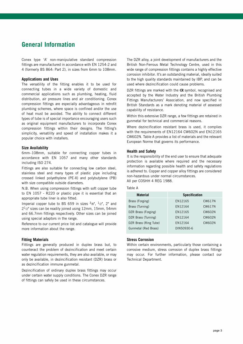
Conex type ‘A’ non-manipulative standard compressionfittings are manufactured in accordance with EN 1254-2 and4 (formerly BS 864: Part 2), in sizes from 6mm to 108mm.
Applications and UsesThe versatility of the fitting enables it to be used forconnecting tubes in a wide variety of domestic andcommercial applications such as plumbing, heating, fluiddistribution, air pressure lines and air conditioning. Conexcompression fittings are especially advantageous in retrofitplumbing schemes, where space is confined and/or the useof heat must be avoided. The ability to connect differenttypes of tube is of special importance encouraging users suchas original equipment manufacturers to incorporate Conexcompression fittings within their designs. The fitting’ssimplicity, versatility and speed of installation makes it apopular choice with installers.
Size Availability6mm–108mm, suitable for connecting copper tubes inaccordance with EN 1057 and many other standardsincluding ISO 274.
Fittings are also suitable for connecting low carbon steel,stainless steel and many types of plastic pipe including crossed linked polyethylene (PE-X) and polybutylene (PB)with size compatible outside diameters.
N.B. When using compression fittings with soft copper tubeto EN 1057 - R220 or plastic pipe it is essential that anappropriate tube liner is also fitted.
Imperial copper tube to BS 659 in sizes 3/8", 1/2", 2" and21/2" sizes can be readily joined using 12mm, 15mm, 54mmand 66.7mm fittings respectively. Other sizes can be joinedusing special adaptors in the range.
Reference to our current price list and catalogue will providemore information about the range.
Fitting MaterialsFittings are generally produced in duplex brass but, tocounteract the problem of dezincification and meet certainwater regulation requirements, they are also available, or mayonly be available, in dezincification resistant (DZR) brass oras dezincification immune gunmetal.
Dezincification of ordinary duplex brass fittings may occurunder certain water supply conditions. The Conex DZR rangeof fittings can safely be used in these circumstances.
The DZR alloy, a joint development of manufacturers and theBritish Non-Ferrous Metal Technology Centre, used in thiswide range of compression fittings contains a highly effectivecorrosion inhibitor. It’s an outstanding material, ideally suitedto the high quality standards maintained by IBP, and can beused where dezincification could cause problems.
DZR fittings are marked with the CR symbol, recognised andaccepted by the Water Industry and the British PlumbingFittings Manufacturers’ Association, and now specified inBritish Standards as a mark denoting material of assessedcapability of resistance.
Within this extensive DZR range, a few fittings are retained ingunmetal for technical and commercial reasons.
Where dezincification resistant brass is used, it complieswith the requirements of EN12164 CW602N and EN12165CW602N. Table A provides a list of materials and the relevantEuropean Norme that governs its performance.
Health and SafetyIt is the responsibility of the end user to ensure that adequateprotection is available where required and the necessaryinformation regarding possible health and safety regulationsis adhered to. Copper and copper alloy fittings are considerednon-hazardous under normal circumstances. All per COSHH 4 REG 1988.
Stress Corrosion Within certain environments, particularly those containing acorrosive medium, stress corrosion of duplex brass fittingsmay occur. For further information, please contact ourTechnical Department.
General Information
Material Specification
Brass (Forging) EN12165 CW617N
Brass (Turning) EN12164 CW617N
DZR Brass (Forging) EN12165 CW602N
DZR Brass (Turning) EN12164 CW602N
DZR Brass (Ring Tube) EN12164 CW602N
Gunmetal (Red Brass) DIN50930-6
Table A
page 4
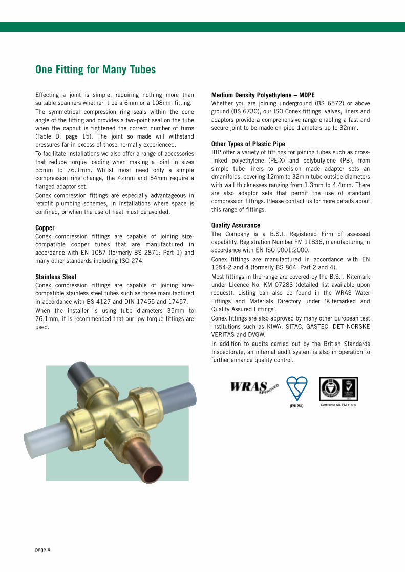
One Fitting for Many Tubes
Effecting a joint is simple, requiring nothing more thansuitable spanners whether it be a 6mm or a 108mm fitting.
The symmetrical compression ring seals within the coneangle of the fitting and provides a two-point seal on the tubewhen the capnut is tightened the correct number of turns(Table D, page 15). The joint so made will withstandpressures far in excess of those normally experienced.
To facilitate installations we also offer a range of accessoriesthat reduce torque loading when making a joint in sizes35mm to 76.1mm. Whilst most need only a simplecompression ring change, the 42mm and 54mm require aflanged adaptor set.
Conex compression fittings are especially advantageous inretrofit plumbing schemes, in installations where space isconfined, or when the use of heat must be avoided.
CopperConex compression fittings are capable of joining size-compatible copper tubes that are manufactured inaccordance with EN 1057 (formerly BS 2871: Part 1) andmany other standards including ISO 274.
Stainless SteelConex compression fittings are capable of joining size-compatible stainless steel tubes such as those manufacturedin accordance with BS 4127 and DIN 17455 and 17457.
When the installer is using tube diameters 35mm to76.1mm, it is recommended that our low torque fittings areused.
Medium Density Polyethylene – MDPEWhether you are joining underground (BS 6572) or aboveground (BS 6730), our ISO Conex fittings, valves, liners andadaptors provide a comprehensive range enabling a fast andsecure joint to be made on pipe diameters up to 32mm.
Other Types of Plastic PipeIBP offer a variety of fittings for joining tubes such as cross-linked polyethylene (PE-X) and polybutylene (PB), from simple tube liners to precision made adaptor sets andmanifolds, covering 12mm to 32mm tube outside diameterswith wall thicknesses ranging from 1.3mm to 4.4mm. Thereare also adaptor sets that permit the use of standardcompression fittings. Please contact us for more details aboutthis range of fittings.
Quality AssuranceThe Company is a B.S.I. Registered Firm of assessedcapability, Registration Number FM 11836, manufacturing inaccordance with EN ISO 9001:2000.
Conex fittings are manufactured in accordance with EN1254-2 and 4 (formerly BS 864: Part 2 and 4).
Most fittings in the range are covered by the B.S.I. Kitemarkunder Licence No. KM 07283 (detailed list available uponrequest). Listing can also be found in the WRAS WaterFittings and Materials Directory under ‘Kitemarked andQuality Assured Fittings’.
Conex fittings are also approved by many other European testinstitutions such as KIWA, SITAC, GASTEC, DET NORSKEVERITAS and DVGW.
In addition to audits carried out by the British StandardsInspectorate, an internal audit system is also in operation tofurther enhance quality control.
BS864-2 / EN 1254 Licence Nos. KM 5932,KM 6854, 7283 & 7825
CER
TIF
IED
TO BRITISH
STAN
DA
RD
(EN1254) Certificate No. FM 11836
page 5
Design
Conex fittings are designed to comply with relevant standardsand to minimise flow restriction.
The symmetrical compression ring provides a seal within thecone of the fitting and a two point seal on the tube.
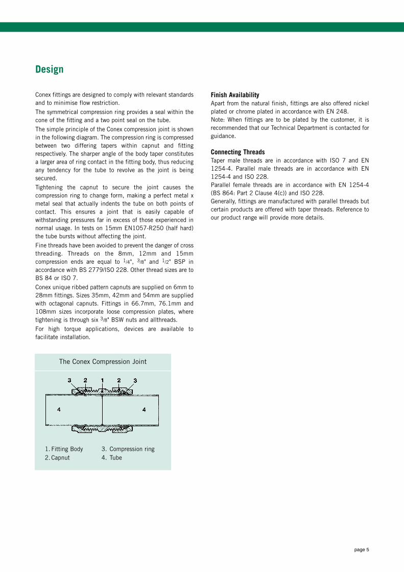
The simple principle of the Conex compression joint is shownin the following diagram. The compression ring is compressedbetween two differing tapers within capnut and fittingrespectively. The sharper angle of the body taper constitutesa larger area of ring contact in the fitting body, thus reducingany tendency for the tube to revolve as the joint is beingsecured.
Tightening the capnut to secure the joint causes thecompression ring to change form, making a perfect metal xmetal seal that actually indents the tube on both points ofcontact. This ensures a joint that is easily capable ofwithstanding pressures far in excess of those experienced innormal usage. In tests on 15mm EN1057-R250 (half hard)the tube bursts without affecting the joint.
Fine threads have been avoided to prevent the danger of crossthreading. Threads on the 8mm, 12mm and 15mmcompression ends are equal to 1/4", 3/8" and 1/2" BSP inaccordance with BS 2779/ISO 228. Other thread sizes are toBS 84 or ISO 7.
Conex unique ribbed pattern capnuts are supplied on 6mm to28mm fittings. Sizes 35mm, 42mm and 54mm are suppliedwith octagonal capnuts. Fittings in 66.7mm, 76.1mm and108mm sizes incorporate loose compression plates, wheretightening is through six 3/8" BSW nuts and allthreads.
For high torque applications, devices are available tofacilitate installation.
Finish AvailabilityApart from the natural finish, fittings are also offered nickelplated or chrome plated in accordance with EN 248.Note: When fittings are to be plated by the customer, it isrecommended that our Technical Department is contacted forguidance.
Connecting ThreadsTaper male threads are in accordance with ISO 7 and EN1254-4. Parallel male threads are in accordance with EN1254-4 and ISO 228.Parallel female threads are in accordance with EN 1254-4(BS 864: Part 2 Clause 4(c)) and ISO 228.Generally, fittings are manufactured with parallel threads butcertain products are offered with taper threads. Reference toour product range will provide more details.
1. Fitting Body2. Capnut
3. Compression ring 4. Tube
The Conex Compression Joint
page 6
Performance
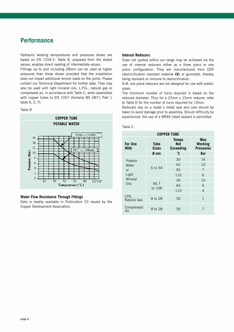
Hydraulic working temperatures and pressures shown arebased on EN 1254-2. Table B, prepared from the statedvalues, enables direct reading of intermediate values.Fittings up to and including 28mm can be used at higherpressures than those shown provided that the installationdoes not impart additional tensile loads on the joints. Pleasecontact our Technical Department for further data. They mayalso be used with light mineral oils, L.P.G., natural gas orcompressed air, in accordance with Table C, when assembledwith copper tubes to EN 1057 (formerly BS 2871: Part 1table X, Z, Y).
Water Flow Resistance Through FittingsData is readily available in Publication 33 issued by theCopper Development Association.
Internal ReducersSizes not quoted within our range may be achieved via theuse of internal reducers either as a three piece or one piece configuration. They are manufactured from DZR(dezincification resistant material CR) or gunmetal, therebybeing resistant or immune to dezincification.N.B. one piece reducers are not designed for use with plasticpipes.The minimum number of turns required is based on thereduced diameter. Thus for a 22mm x 15mm reducer, referto Table D for the number of turns required for 15mm.Reducers rely on a metal x metal seal and care should betaken to avoid damage prior to assembly. Should difficulty beexperienced, the use of a WRAS listed sealant is permitted.COPPER TUBE
POTABLE WATER
Table B
COPPER TUBETemps Max
For Use Tube Not WorkingWith Sizes Exceeding Pressures
Ø mm ˚C Bar
30 1665 10
6 to 54 95 7110 630 10
66.7 65 6to 108
110 4
8 to 28 30 1
8 to 28 30 7
PotableWaterorLightMineralOils
Table C
LPG, Natural Gas
CompressedAir
page 7
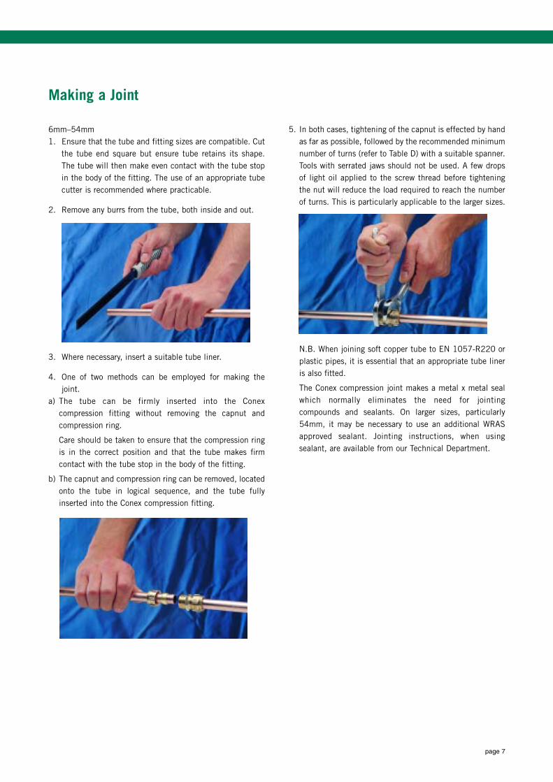
6mm–54mm1. Ensure that the tube and fitting sizes are compatible. Cut
the tube end square but ensure tube retains its shape.The tube will then make even contact with the tube stopin the body of the fitting. The use of an appropriate tubecutter is recommended where practicable.
2. Remove any burrs from the tube, both inside and out.
3. Where necessary, insert a suitable tube liner.
4. One of two methods can be employed for making thejoint.
a) The tube can be firmly inserted into the Conexcompression fitting without removing the capnut andcompression ring.
Care should be taken to ensure that the compression ringis in the correct position and that the tube makes firmcontact with the tube stop in the body of the fitting.
b) The capnut and compression ring can be removed, locatedonto the tube in logical sequence, and the tube fullyinserted into the Conex compression fitting.
5. In both cases, tightening of the capnut is effected by handas far as possible, followed by the recommended minimumnumber of turns (refer to Table D) with a suitable spanner.Tools with serrated jaws should not be used. A few dropsof light oil applied to the screw thread before tighteningthe nut will reduce the load required to reach the numberof turns. This is particularly applicable to the larger sizes.
N.B. When joining soft copper tube to EN 1057-R220 orplastic pipes, it is essential that an appropriate tube lineris also fitted.
The Conex compression joint makes a metal x metal sealwhich normally eliminates the need for jointingcompounds and sealants. On larger sizes, particularly54mm, it may be necessary to use an additional WRASapproved sealant. Jointing instructions, when usingsealant, are available from our Technical Department.
Making a Joint
page 8
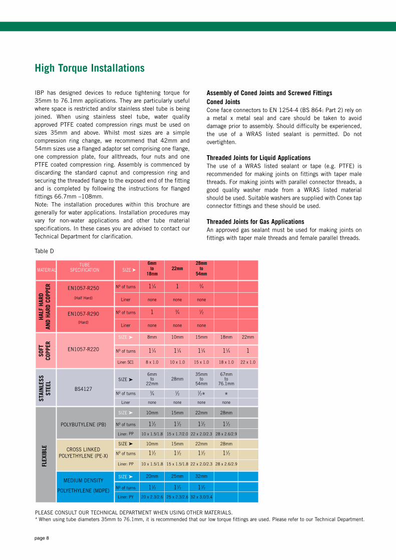
High Torque Installations
IBP has designed devices to reduce tightening torque for35mm to 76.1mm applications. They are particularly usefulwhere space is restricted and/or stainless steel tube is beingjoined. When using stainless steel tube, water qualityapproved PTFE coated compression rings must be used onsizes 35mm and above. Whilst most sizes are a simplecompression ring change, we recommend that 42mm and54mm sizes use a flanged adaptor set comprising one flange,one compression plate, four allthreads, four nuts and onePTFE coated compression ring. Assembly is commenced bydiscarding the standard capnut and compression ring andsecuring the threaded flange to the exposed end of the fittingand is completed by following the instructions for flangedfittings 66.7mm –108mm.Note: The installation procedures within this brochure aregenerally for water applications. Installation procedures mayvary for non-water applications and other tube materialspecifications. In these cases you are advised to contact ourTechnical Department for clarification.
Assembly of Coned Joints and Screwed FittingsConed JointsCone face connectors to EN 1254-4 (BS 864: Part 2) rely ona metal x metal seal and care should be taken to avoiddamage prior to assembly. Should difficulty be experienced,the use of a WRAS listed sealant is permitted. Do notovertighten.
Threaded Joints for Liquid ApplicationsThe use of a WRAS listed sealant or tape (e.g. PTFE) isrecommended for making joints on fittings with taper malethreads. For making joints with parallel connector threads, agood quality washer made from a WRAS listed materialshould be used. Suitable washers are supplied with Conex tapconnector fittings and these should be used.
Threaded Joints for Gas ApplicationsAn approved gas sealant must be used for making joints onfittings with taper male threads and female parallel threads.
6mm 28mmto 22mm to
18mm 54mm
EN1057-R250 No of turns 11⁄4 1 3⁄4
(Half Hard) Liner none none none
EN1057-R290 No of turns 1 3⁄4 1⁄2
(Hard)Liner none none none
SIZE ä 8mm 10mm 15mm 18mm 22mm
EN1057-R220 No of turns 11⁄4 11⁄4 11⁄4 11⁄4 1
Liner: SC1 8 x 1.0 10 x 1.0 15 x 1.0 18 x 1.0 22 x 1.0
6mm 35mm 67mmSIZE ä to 28mm to to
22mm 54mm 76.1mmBS4127
No of turns 3⁄4 1⁄2 1⁄2* *Liner none none none none
SIZE ä 10mm 15mm 22mm 28mm
POLYBUTYLENE (PB) No of turns 11⁄2 11⁄2 11⁄2 11⁄2
Liner: PP 10 x 1.5/1.8 15 x 1.7/2.0 22 x 2.0/2.3 28 x 2.6/2.9
CROSS LINKEDSIZE ä 10mm 15mm 22mm 28mm
No of turns 11⁄2 11⁄2 11⁄2 11⁄2POLYETHYLENE (PE-X)
Liner: PP 10 x 1.5/1.8 15 x 1.5/1.8 22 x 2.0/2.3 28 x 2.6/2.9
MEDIUM DENSITYSIZE ä 20mm 25mm 32mm
POLYETHYLENE (MDPE)No of turns 11⁄2 11⁄2 11⁄2
Liner: PY 20 x 2.3/2.6 25 x 2.3/2.6 32 x 3.0/3.4
FLEX
IBLE
SOFT
COPP
ER
TUBE MATERIAL SPECIFICATION SIZE ä
Table D
PLEASE CONSULT OUR TECHNICAL DEPARTMENT WHEN USING OTHER MATERIALS.* When using tube diameters 35mm to 76.1mm, it is recommended that our low torque fittings are used. Please refer to our Technical Department.
STAI
NLES
SST
EEL
HALF
HAR
DAN
D HA
RD C
OPPE
R
page 9
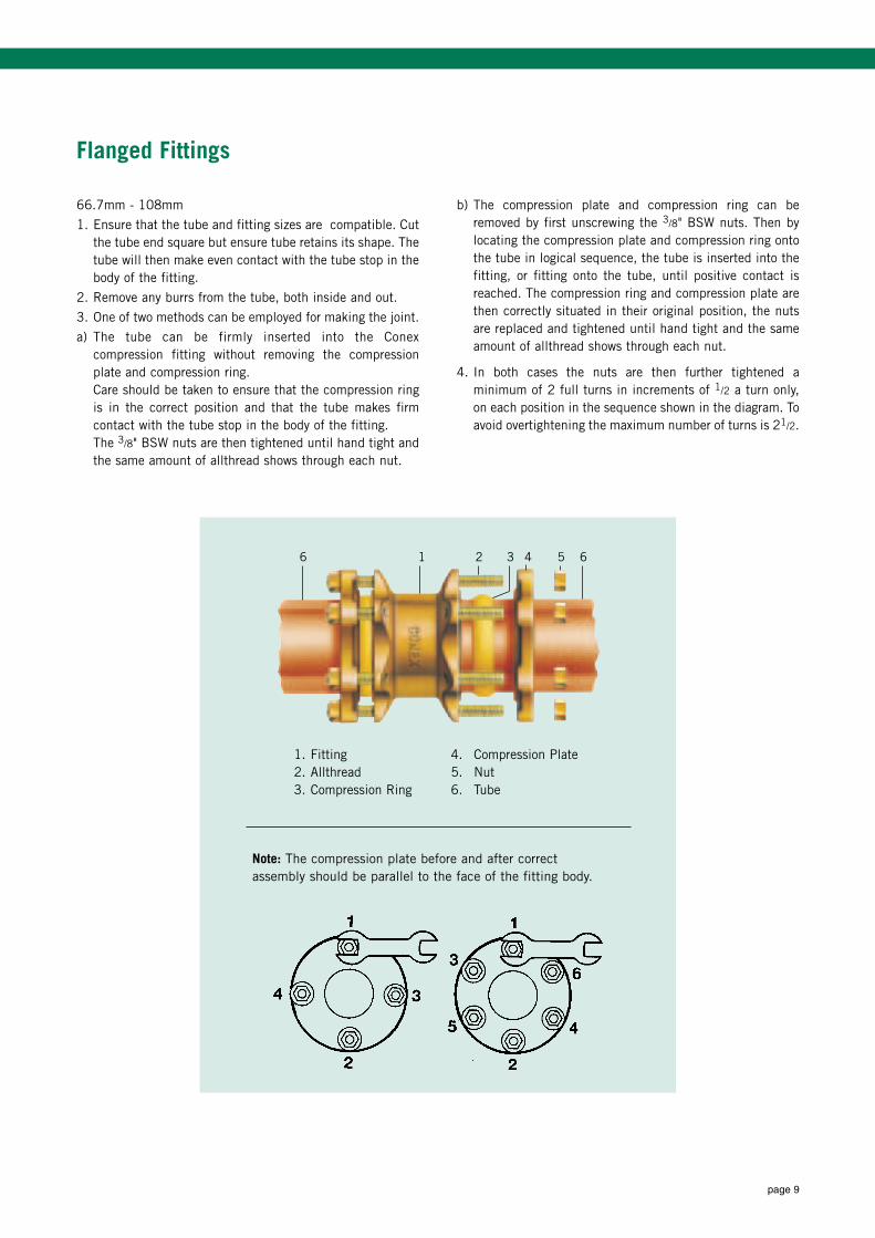
Flanged Fittings
66.7mm - 108mm
1. Ensure that the tube and fitting sizes are compatible. Cutthe tube end square but ensure tube retains its shape. Thetube will then make even contact with the tube stop in thebody of the fitting.
2. Remove any burrs from the tube, both inside and out.
3. One of two methods can be employed for making the joint.
a) The tube can be firmly inserted into the Conexcompression fitting without removing the compressionplate and compression ring.Care should be taken to ensure that the compression ringis in the correct position and that the tube makes firmcontact with the tube stop in the body of the fitting.The 3/8" BSW nuts are then tightened until hand tight andthe same amount of allthread shows through each nut.
b) The compression plate and compression ring can beremoved by first unscrewing the 3/8" BSW nuts. Then bylocating the compression plate and compression ring ontothe tube in logical sequence, the tube is inserted into thefitting, or fitting onto the tube, until positive contact isreached. The compression ring and compression plate arethen correctly situated in their original position, the nutsare replaced and tightened until hand tight and the sameamount of allthread shows through each nut.
4. In both cases the nuts are then further tightened aminimum of 2 full turns in increments of 1/2 a turn only,on each position in the sequence shown in the diagram. Toavoid overtightening the maximum number of turns is 21/2.
1. Fitting 4. Compression Plate2. Allthread 5. Nut3. Compression Ring 6. Tube
Note: The compression plate before and after correctassembly should be parallel to the face of the fitting body.
6 1 2 3 4 5 6
page 10
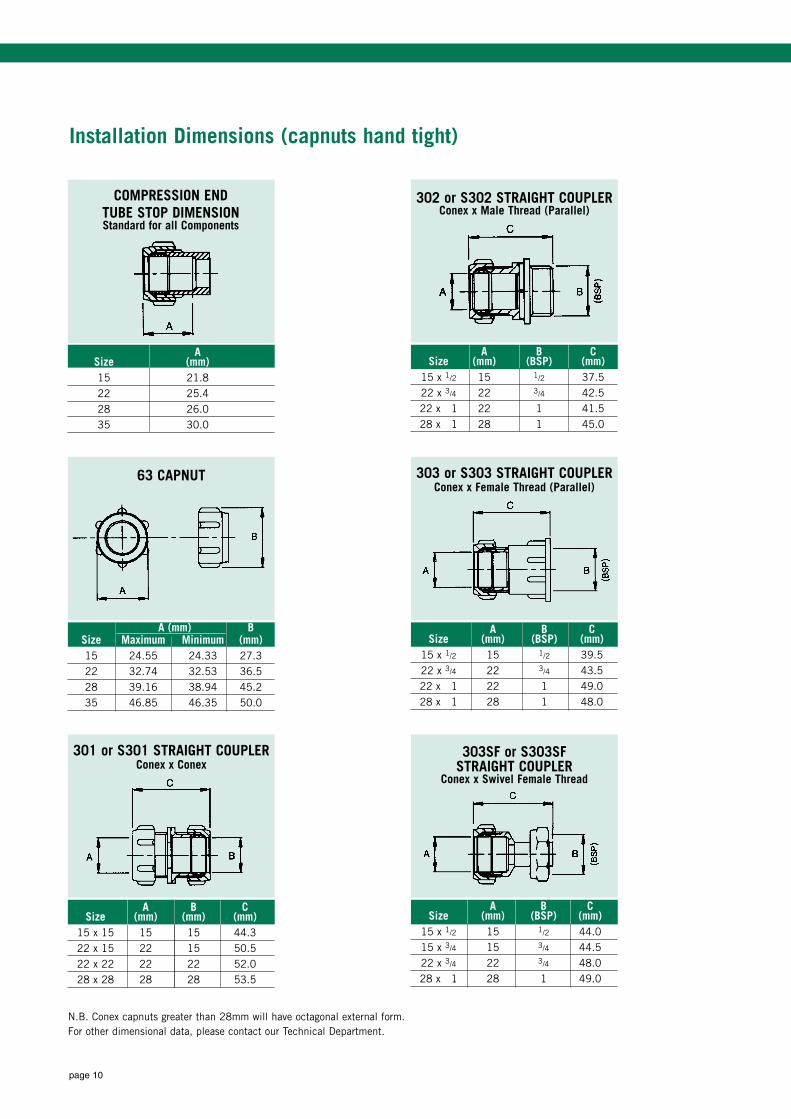
Installation Dimensions (capnuts hand tight)
N.B. Conex capnuts greater than 28mm will have octagonal external form.For other dimensional data, please contact our Technical Department.
ASize (mm)15 21.822 25.428 26.035 30.0
302 or S302 STRAIGHT COUPLERConex x Male Thread (Parallel)
A B CSize (mm) (BSP) (mm)
15 x 1/2 15 1/2 37.522 x 3/4 22 3/4 42.522 x 1 22 1 41.528 x 1 28 1 45.0
63 CAPNUT
A (mm) BSize Maximum Minimum (mm)15 24.55 24.33 27.322 32.74 32.53 36.528 39.16 38.94 45.235 46.85 46.35 50.0
303 or S303 STRAIGHT COUPLERConex x Female Thread (Parallel)
A B CSize (mm) (BSP) (mm)
15 x 1/2 15 1/2 39.522 x 3/4 22 3/4 43.522 x 1 22 1 49.028 x 1 28 1 48.0
301 or S301 STRAIGHT COUPLERConex x Conex
A B CSize (mm) (mm) (mm)
15 x 15 15 15 44.322 x 15 22 15 50.522 x 22 22 22 52.028 x 28 28 28 53.5
303SF or S303SF STRAIGHT COUPLER
Conex x Swivel Female Thread
A B CSize (mm) (BSP) (mm)
15 x 1/2 15 1/2 44.015 x 3/4 15 3/4 44.522 x 3/4 22 3/4 48.028 x 1 28 1 49.0
COMPRESSION ENDTUBE STOP DIMENSIONStandard for all Components
page 11
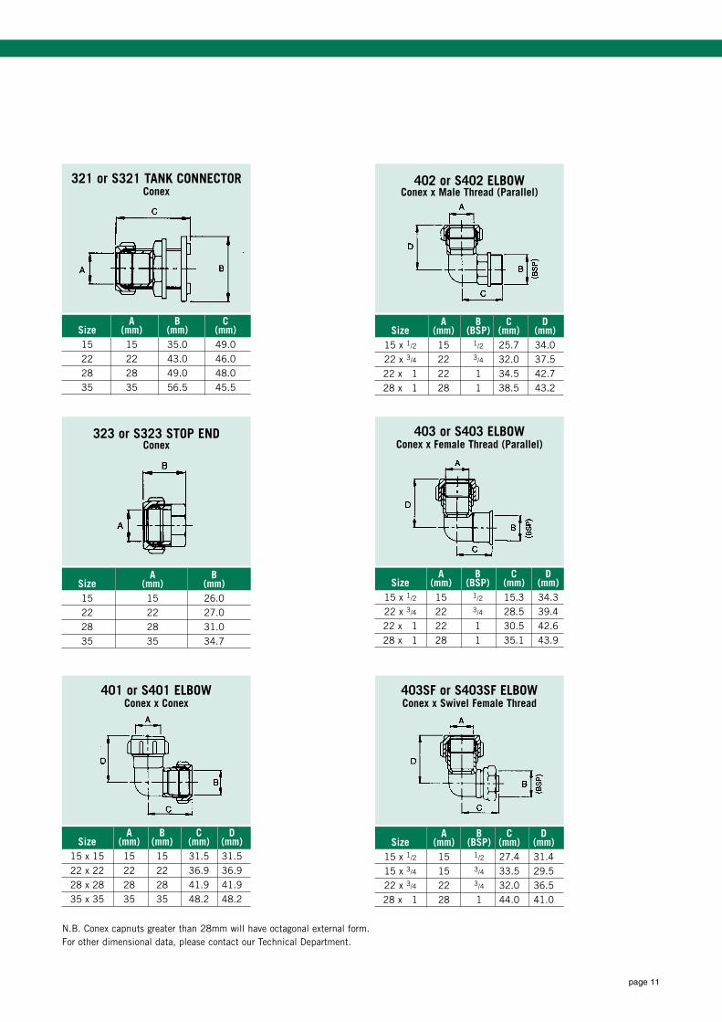
N.B. Conex capnuts greater than 28mm will have octagonal external form.For other dimensional data, please contact our Technical Department.
321 or S321 TANK CONNECTORConex
A B CSize (mm) (mm) (mm)15 15 35.0 49.022 22 43.0 46.028 28 49.0 48.035 35 56.5 45.5
402 or S402 ELBOWConex x Male Thread (Parallel)
A B C DSize (mm) (BSP) (mm) (mm)
15 x 1/2 15 1/2 25.7 34.022 x 3/4 22 3/4 32.0 37.522 x 1 22 1 34.5 42.728 x 1 28 1 38.5 43.2
323 or S323 STOP ENDConex
A BSize (mm) (mm)15 15 26.022 22 27.028 28 31.035 35 34.7
403 or S403 ELBOWConex x Female Thread (Parallel)
A B C DSize (mm) (BSP) (mm) (mm)
15 x 1/2 15 1/2 15.3 34.322 x 3/4 22 3/4 28.5 39.422 x 1 22 1 30.5 42.628 x 1 28 1 35.1 43.9
401 or S401 ELBOWConex x Conex
A B C DSize (mm) (mm) (mm) (mm)
15 x 15 15 15 31.5 31.522 x 22 22 22 36.9 36.928 x 28 28 28 41.9 41.935 x 35 35 35 48.2 48.2
403SF or S403SF ELBOWConex x Swivel Female Thread
A B C DSize (mm) (BSP) (mm) (mm)
15 x 1/2 15 1/2 27.4 31.415 x 3/4 15 3/4 33.5 29.522 x 3/4 22 3/4 32.0 36.528 x 1 28 1 44.0 41.0
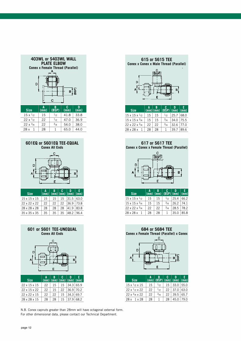
page 12
N.B. Conex capnuts greater than 28mm will have octagonal external form.For other dimensional data, please contact our Technical Department.
615 or S615 TEEConex x Conex x Male Thread (Parallel)
A B C D ESize (mm) (mm) (BSP) (mm) (mm)
15 x 15 x 1/2 15 15 1/2 25.7 68.015 x 15 x 3/4 15 15 3/4 34.0 75.522 x 22 x 3/4 22 22 3/4 32.6 77.028 x 28 x 1 28 28 1 39.7 89.6
A B C DSize (mm) (BSP) (mm) (mm)
15 x 1/2 15 1/2 41.8 33.822 x 1/2 22 1/2 47.0 36.922 x 3/4 22 3/4 54.0 38.028 x 1 28 1 65.0 44.0
617 or S617 TEEConex x Conex x Female Thread (Parallel)
A B C D ESize (mm) (mm) (BSP) (mm) (mm)
15 x 15 x 1/2 15 15 1/2 25.4 66.215 x 15 x 3/4 15 15 3/4 26.2 74.122 x 22 x 3/4 22 22 3/4 28.5 78.228 x 28 x 1 28 28 1 35.0 85.8
601EQ or S601EQ TEE-EQUALConex All Ends
A B C D ESize (mm) (mm) (mm) (mm) (mm)
15 x 15 x 15 15 15 15 31.5 63.022 x 22 x 22 22 22 22 36.9 73.828 x 28 x 28 28 28 28 41.9 83.835 x 35 x 35 35 35 35 48.2 96.4
684 or S684 TEEConex x Female Thread (Parallel) x Conex
A B C D ESize (mm) (BSP) (mm) (mm) (mm)
15 x 1/2 x 15 15 1/2 15 33.0 55.022 x 1/2 x 22 22 1/2 22 37.0 63.022 x 3/4 x 22 22 3/4 22 39.5 65.728 x 1 x 28 28 1 28 45.0 79.0
601 or S601 TEE-UNEQUALConex All Ends
A B C D ESize (mm) (mm) (mm) (mm) (mm)
22 x 15 x 15 22 15 15 34.3 65.922 x 15 x 22 22 15 22 36.9 70.222 x 22 x 15 22 22 15 34.3 69.728 x 28 x 15 28 28 15 37.9 68.2
403WL or S403WL WALL PLATE ELBOW
Conex x Female Thread (Parallel)

Please see our website for the full Conex range at www.ibpconex.co.uk
or contact the sales team on: 0121 557 2831 or email: [email protected]
For technical information please email our technical department at: [email protected]
Conex Universal Limited: Whitehall Road, Tipton, West Midlands, DY4 7JU, UNITED KINGDOM. Tel: +44 (0)121 557 2831 Fax: +44 (0)121 520 8778email: [email protected], [email protected], [email protected], [email protected], web: www.ibpgroup.com, www.ibpconex.co.uk
an IBP GROUP company.