Compression Fatigue Crack Growth in Nacre and Its ... · ao Hamza S (2016) Compression Fatigue...
7
Research Article Open Access Hamza, J Material Sci Eng 2016, 6:1 DOI: 10.4172/2169-0022.1000301 Research Article OMICS International Journal of Material Sciences & Engineering J o u r n a l o f M a t e r i a l S c i e n c e s & E n g i n e e r i n g ISSN: 2169-0022 Volume 6 • Issue 1 • 1000301 J Material Sci Eng, an open access journal ISSN: 2169-0022 Compression Fatigue Crack Growth in Nacre and Its Implication on the Mechanical Performance of Orthopedic Implants Hamza S* National Institute of Apllied Sciences and Technology, Tunisia, Tunisia Abstract The aim of the present review is to present some phenomenological observations on compression fatigue crack propagation of nacre samples. The first part of the paper reviews the characteristics of hierarchical structure and the mechanical properties of nacre, which characterize its specific properties. We have investigated the main chemical constituents of nacre and determined their mineral elements. Electron microscopy studies revealed that nacre is composed of a single-crystal aragonite. In the second part of the paper samples of nacre have been tested in compression-compression fatigue under cyclic loading and a Paris curve have been constructed at a fatigue ratio of about 10, subjected to a 30 Hz sinusoidal compressive load. It has been demonstrated that two driving forces ΔK and K max mainly govern the overall fatigue crack growth of nacre. Nacre shows considerable ability to stop cracking. By means of axial compression tests, we identified a single elastic and inelastic property. Measurements based on experiments were first done. Mean values of compressive strength and modulus of elasticity were obtained for several samples. A three-point bending test was performed on polished nacre samples according to the international standards for Young’s modulus, bending strength. An attempt is made to explain qualitatively the mechanical behavior of nacre in terms of its submicroscopic structure. It is concluded that the precise geometric arrangement of the plates is highly important. The results obtained provide a director for the design of orthopedic implants. *Corresponding author: Hamza S, National Institute of Applied Sciences and Technology, Tunisia, Tunisia, Tel: 21671703829; E-mail: [email protected] Received June 27, 2016; Accepted November 15, 2016; Published November 25, 2016 Citation: Hamza S (2016) Compression Fatigue Crack Growth in Nacre and Its Implication on the Mechanical Performance of Orthopedic Implants. J Material Sci Eng 6: 301. doi: 10.4172/2169-0022.1000301 Copyright: © 2016 Hamza S. This is an open-access article distributed under the terms of the Creative Commons Attribution License, which permits unrestricted use, distribution, and reproduction in any medium, provided the original author and source are credited. Keywords: Nacre; Fatigue; Compression; Biomedical applications; Material property Introduction All engineering applications require the evaluation of, the fatigue behavior under various loading modes and the fast fracture strength, therefore conventional theory was established [1-4]. Observations of controlled crack initiation in cyclic compression of notched metallic materials were first reported in the 1960s. Hubbard reported a fracture mechanics based study of crack growth in a center-notched plate [5]. Similar observations have been made subsequently in ceramics [6-8]. e mechanism of a mode I fatigue is dictated by the development of a cyclic plastic zone ahead of the notch tip upon unloading from the far-field compressive stress. Its crack propagation is in the direction normal to the imposed compression axis [2,7]. As crack advance under far-field, cyclic compression is governed by a local tensile stress, the influence of microstructure on crack growth behavior is found to be similar to that seen under far-field cyclic tension [6-10]. However, several important points remain to be discussed. e mechanical properties of nacre have been previously reported, although investigations to date concentrated on stiffness and fracture toughness [11-15]. In fact they clearly showed the superiority of the mechanical properties of nacre while focusing on its stiffness, however the fatigue crack growth in nacre remains significant, to propose its use for orthopedic implants. Investigations have shown that stable fatigue crack growth in ceramics can occur on notched samples under compressive cyclic loads [16]. is result provides a convenient method to stuffy fatigue behavior in nacre, since it permits to avoid most of the difficulties associated with the brittleness of the sample during fatigue. Compression- compression fatigue can also be used to introduce a sharp crack in a brittle material sample in order to perform more complicated fatigue cracking studies [9]. In tension-tension loading it is generally accepted that the crack driving force is calculated based on the full-applied stress intensity ∆K [10]. However, if compression-compression loading is introduced, in several articles [17,18], we have shown that the fundamental material behavior is represented by the constant amplitude fatigue loading results governed by the two driving forces, ΔK and K max . ese two driving forces conditions must be satisfied simultaneously for any crack to grow. Compression fatigue tests were also performed on several other ceramics. In the present paper, this concept has been extended to analyze the compression-compression fatigue behavior. e analysis indicates that to characterize accurately the entire crack growth region of loading for R<0, one must include both the internal stresses and the applied stresses [10,19-21]. e formation of seashell nacre is a slow process in nature. Seashell absorbs mineral elements and organic matters in seawater to form inorganic nanoplatelets and macromolecules, which deposit alternately to form compact brick-and-mortar structure of nacre [22-24]. Nacre is a calcified structure that forms the lustrous inner layer of many marine oysters. is lustrous material has intrigued scientist for many years because of its sophisticated structure [25]. It is composed of calcium carbonate crystals organized in multiple layers of thin tablets of aragonite. Fragments of nacre from the bivalve Pinctada radiata elicit a biological response when implanted into the bone. Nacre is composed of 95wt% aragonite (CaCO 3 ) and 5 wt% organic materials [26,27]. It is well known that it exhibits high fracture toughness, much greater than that of monolithic aragonite, because of its ingenious structure.
Transcript of Compression Fatigue Crack Growth in Nacre and Its ... · ao Hamza S (2016) Compression Fatigue...
Research Article Open Access
Hamza, J Material Sci Eng 2016, 6:1DOI: 10.4172/2169-0022.1000301
Research Article OMICS International
Journal of Material Sciences & Engineering Jo
urna
l of M
aterial Sciences & Engineering
ISSN: 2169-0022
Volume 6 • Issue 1 • 1000301J Material Sci Eng, an open access journalISSN: 2169-0022
Compression Fatigue Crack Growth in Nacre and Its Implication on the Mechanical Performance of Orthopedic ImplantsHamza S*National Institute of Apllied Sciences and Technology, Tunisia, Tunisia
AbstractThe aim of the present review is to present some phenomenological observations on compression fatigue
crack propagation of nacre samples. The first part of the paper reviews the characteristics of hierarchical structure and the mechanical properties of nacre, which characterize its specific properties. We have investigated the main chemical constituents of nacre and determined their mineral elements. Electron microscopy studies revealed that nacre is composed of a single-crystal aragonite. In the second part of the paper samples of nacre have been tested in compression-compression fatigue under cyclic loading and a Paris curve have been constructed at a fatigue ratio of about 10, subjected to a 30 Hz sinusoidal compressive load. It has been demonstrated that two driving forces ΔK and Kmax mainly govern the overall fatigue crack growth of nacre. Nacre shows considerable ability to stop cracking. By means of axial compression tests, we identified a single elastic and inelastic property. Measurements based on experiments were first done. Mean values of compressive strength and modulus of elasticity were obtained for several samples. A three-point bending test was performed on polished nacre samples according to the international standards for Young’s modulus, bending strength. An attempt is made to explain qualitatively the mechanical behavior of nacre in terms of its submicroscopic structure. It is concluded that the precise geometric arrangement of the plates is highly important. The results obtained provide a director for the design of orthopedic implants.
*Corresponding author: Hamza S, National Institute of Applied Sciences and Technology, Tunisia, Tunisia, Tel: 21671703829; E-mail: [email protected]
Received June 27, 2016; Accepted November 15, 2016; Published November 25, 2016
Citation: Hamza S (2016) Compression Fatigue Crack Growth in Nacre and Its Implication on the Mechanical Performance of Orthopedic Implants. J Material Sci Eng 6: 301. doi: 10.4172/2169-0022.1000301
Copyright: © 2016 Hamza S. This is an open-access article distributed under the terms of the Creative Commons Attribution License, which permits unrestricted use, distribution, and reproduction in any medium, provided the original author and source are credited.
Keywords: Nacre; Fatigue; Compression; Biomedical applications; Material property
IntroductionAll engineering applications require the evaluation of, the fatigue
behavior under various loading modes and the fast fracture strength, therefore conventional theory was established [1-4]. Observations of controlled crack initiation in cyclic compression of notched metallic materials were first reported in the 1960s. Hubbard reported a fracture mechanics based study of crack growth in a center-notched plate [5]. Similar observations have been made subsequently in ceramics [6-8].
The mechanism of a mode I fatigue is dictated by the development of a cyclic plastic zone ahead of the notch tip upon unloading from the far-field compressive stress. Its crack propagation is in the direction normal to the imposed compression axis [2,7]. As crack advance under far-field, cyclic compression is governed by a local tensile stress, the influence of microstructure on crack growth behavior is found to be similar to that seen under far-field cyclic tension [6-10]. However, several important points remain to be discussed.
The mechanical properties of nacre have been previously reported, although investigations to date concentrated on stiffness and fracture toughness [11-15]. In fact they clearly showed the superiority of the mechanical properties of nacre while focusing on its stiffness, however the fatigue crack growth in nacre remains significant, to propose its use for orthopedic implants.
Investigations have shown that stable fatigue crack growth in ceramics can occur on notched samples under compressive cyclic loads [16]. This result provides a convenient method to stuffy fatigue behavior in nacre, since it permits to avoid most of the difficulties associated with the brittleness of the sample during fatigue. Compression-compression fatigue can also be used to introduce a sharp crack in a brittle material sample in order to perform more complicated fatigue cracking studies [9].
In tension-tension loading it is generally accepted that the crack driving force is calculated based on the full-applied stress intensity ∆K
[10]. However, if compression-compression loading is introduced, in several articles [17,18], we have shown that the fundamental material behavior is represented by the constant amplitude fatigue loading results governed by the two driving forces, ΔK and Kmax. These two driving forces conditions must be satisfied simultaneously for any crack to grow. Compression fatigue tests were also performed on several other ceramics. In the present paper, this concept has been extended to analyze the compression-compression fatigue behavior. The analysis indicates that to characterize accurately the entire crack growth region of loading for R<0, one must include both the internal stresses and the applied stresses [10,19-21].
The formation of seashell nacre is a slow process in nature. Seashell absorbs mineral elements and organic matters in seawater to form inorganic nanoplatelets and macromolecules, which deposit alternately to form compact brick-and-mortar structure of nacre [22-24]. Nacre is a calcified structure that forms the lustrous inner layer of many marine oysters. This lustrous material has intrigued scientist for many years because of its sophisticated structure [25]. It is composed of calcium carbonate crystals organized in multiple layers of thin tablets of aragonite. Fragments of nacre from the bivalve Pinctada radiata elicit a biological response when implanted into the bone. Nacre is composed of 95wt% aragonite (CaCO3) and 5 wt% organic materials [26,27]. It is well known that it exhibits high fracture toughness, much greater than that of monolithic aragonite, because of its ingenious structure.
Citation: Hamza S (2016) Compression Fatigue Crack Growth in Nacre and Its Implication on the Mechanical Performance of Orthopedic Implants. J Material Sci Eng 6: 301. doi: 10.4172/2169-0022.1000301
Page 2 of 7
Volume 6 • Issue 1 • 1000301J Material Sci Eng, an open access journalISSN: 2169-0022
Moreover it includes columnar architectures and sheet tiles, mineral bridges, polygonal nanograins, nanoasperities, plastic microbuckling, crack deflection, and interlocking bricks, which exhibit a remarkable combination of stiffness, low weight and strength. Researchers studied the mechanical structure of nacre, the shiny layer on the inside of seashells, and tried to improve its mechanical properties [28,29]. Materials scientists have spent many years analyzing the structure of the aragonitic calcium carbonate layers, their crystallography, their defect structure as well as their growth mechanisms [30].
Nacre has the same density as bone, but its micro-hardness is greater than that of stainless steel 316L. Studies have provided good evidence of the biocompatibility and osteogenic activity of nacre and recent results have demonstrated that implants of nacre are suitable for replacing defective bone [28]. The long-term function and fixation of the implant depend on the biological, physical-chemical and mechanical characteristics of the whole structure and these characteristics change over time following the trend of tissue response and surface alterations [31].
This work gives an overview of our research that describes quantitatively the specific role of detailed nacre structure under a stress-strain test and how it responds to it. We detail the role of each nanostructure of nacre responsible of its mechanics and deformation behavior. Moreover we elucidate the key mechanisms responsible for the unique mechanical behavior of nacre.
Many studies have shown that strength degradation occurs at a faster rate than anticipated from the static loading test. In addition there is reliable evidence, particularly from studies [32-34], that crack growth takes place when notches are cyclically loaded in compression. The fatigue life of structure components is generally considered to be composed of the crack initiation life and the crack propagation life [35]. Given the relatively short crack propagation phase, due to fast crack growth and to give a conservative prediction, the fatigue crack initiation was defined as the fatigue life in this study.
Materials and MethodsMaterial
Shells of oyster, were freshly collected, soaked for 14 days in 5% NaOH, lightly scrubbed after soaking, then rinsed in distilled water and dried with N2 at room temperature. After they had dried completely, we cut the layer of nacre with a grinding wheel.
Nacre is the most aragonitic microstructure. It is a composite with a layered structure of brick (aragonite platelets) and mortar (protein-poly-saccharide matrix). Its layered microstructure confers nacre its precious pearly luster [36,37]. Nacre can be used as bone graft substitutes for filling bone defects because of their similar chemical composition to the mineral part of bone and their excellent biocompatibility [28].
A total of twenty nacre samples from the shells of the mollusc (Pinctada maxima) were investigated. The samples were polished and the surfaces were examined for scratches by light microscope and corrected if required. During this entire finishing process, the samples were kept moistened. The nacre samples had no growth lines and only the white variety was used to avoid planes of weakness caused by inhomogeneities or inclusions. To confirm the orientation of the nacre samples, scanning electron microscopy (SEM) was performed.
Scanning electron microscopy and X-ray microanalysis
The microstructures of nacre were assessed using the Scanning
Electron Microscopy (SEM). The observations were performed on gold-coated specimens and investigated at an acceleration voltage of 15 kV for both samples. Micron-scale images were acquired using tapping mode, with a resolution of about 50 nm, into a computer-equipped tool with a resolution of about 1 to 5 nm and a wide range of applications.
The chemical characterization of the samples was performed using energy dispersive X-ray Microanalysis (EDS). EDS allows the determination of the type of calcium phosphate present in samples. EDS was recorded in constant pass energy mode and expressed as intensity on the Y-axis versus binding energy on X-axis.
Experimental design and mechanical tests
The used machine is of the type MTS 858 Mini Bionix servo-hydraulic. The axial load is ranging between ±25kN with a standard displacement of ±50 mm. The computer controlling the machine determines the uniaxial compression, the three-point bending and the fatigue performance in ambient conditions. The range of forces between which the modulus was calculated to obtain reliable results was limited to 10% Fmax < Fmeasured < 90% Fmax.
Compression tests: The compression test specimens of nacre were tested in both parallel and perpendicular positions to shell growth bands of nacre under quasi-static strain rates. Five specimens were machined to the nominal dimensions of 5 mm in diameter and 10 mm in length. These dimensions are conform to the “short” length-to-diameter ratio of 2 per the ASTM E9-89A specification in order to minimize the likelihood of buckling under the compressive load. Specimens were first polished so that the two surfaces were parallel and flat. Compressive stress and strain were calculated and plotted as a stress-strain diagram. The stress-strain tests were performed at crosshead speeds of 0.05 mm/min. The yield stress (σe0.2) from each test was determined by the 0.2% offset criterion. The static Young’s modulus (E) was calculated and maximum compression stress were determined. All tests were performed in duplicate.
Bending strength: Ten specimens of nacre were performed by carrying out bending test in various loading directions. The specimens tested in bending had the same length of 40 mm and cross-sectional areas of approximately 5 × 5 mm. The support span is 34 mm. The test is stopped when the specimen breaks. With great attention and precision, parallel sides and uniform orientation of growth plans throughout the samples were obtained. The three-points bending tests were instructed as in ASTM standards D790.
The speed of the crosshead of the test machine was 0.1 mm/min, which was established in preliminary testing to achieve constancy and linearity. The samples were loaded until fracture, while the maximum force (Fmax) at the time of fracture was recorded. The force applied in the center allows the determination of flexural modulus and flexural strength.
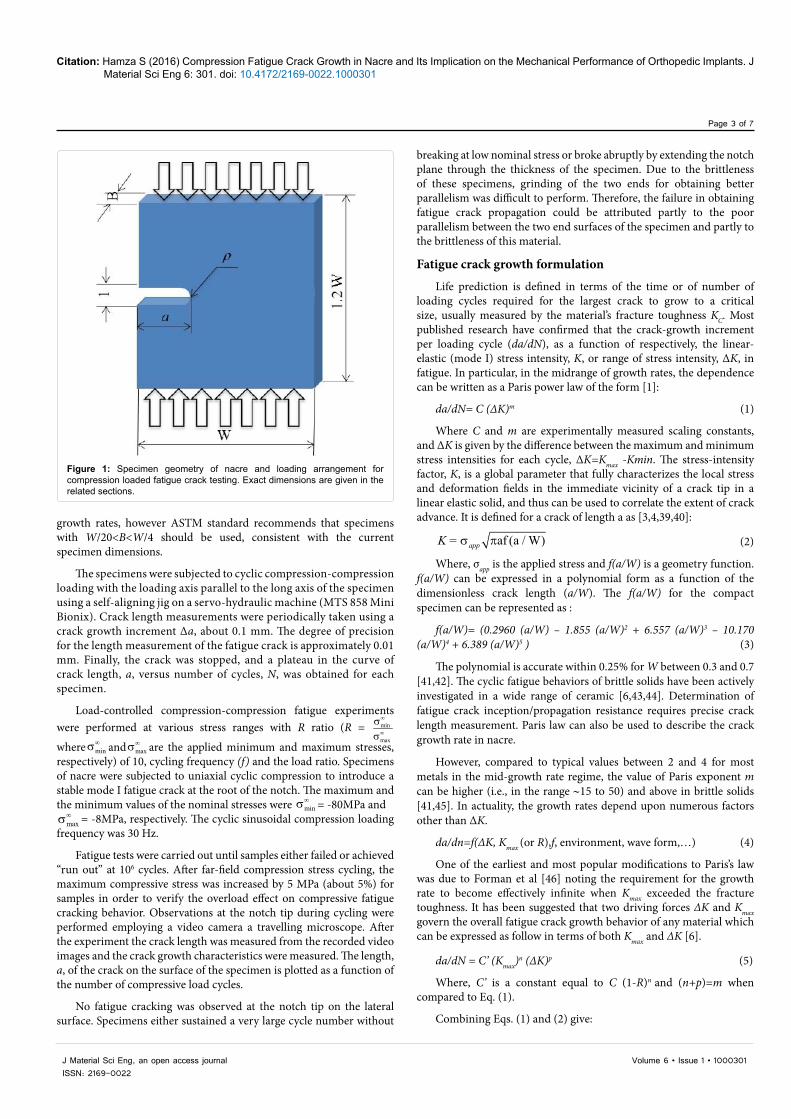
Fatigue tests: Studies on compression-compression fatigue was carried out on nacre employing twenty compact specimens, were machined with a thickness, B=3 mm, width, W=21.5 mm and initial crack length, a=4.3 mm. They were all orientated with the nominal crack-growth direction (Figure 1). The specimens were sectioned and a notch was introduced with a circular diamond low-speed saw, which produced a notch tip radius ρ=0.5 mm in all the specimens. Before testing, both side surfaces of the specimens were polished up to 6µm finish, using diamond wheels. All the specimens used satisfied the ASTM Standard E647-00 test size requirements [38]. There are no “plane strain vs. plane stress” requirements for the measurement of
Citation: Hamza S (2016) Compression Fatigue Crack Growth in Nacre and Its Implication on the Mechanical Performance of Orthopedic Implants. J Material Sci Eng 6: 301. doi: 10.4172/2169-0022.1000301
Page 3 of 7
Volume 6 • Issue 1 • 1000301J Material Sci Eng, an open access journalISSN: 2169-0022
breaking at low nominal stress or broke abruptly by extending the notch plane through the thickness of the specimen. Due to the brittleness of these specimens, grinding of the two ends for obtaining better parallelism was difficult to perform. Therefore, the failure in obtaining fatigue crack propagation could be attributed partly to the poor parallelism between the two end surfaces of the specimen and partly to the brittleness of this material.
Fatigue crack growth formulation
Life prediction is defined in terms of the time or of number of loading cycles required for the largest crack to grow to a critical size, usually measured by the material’s fracture toughness KC. Most published research have confirmed that the crack-growth increment per loading cycle (da/dN), as a function of respectively, the linear-elastic (mode I) stress intensity, K, or range of stress intensity, ∆K, in fatigue. In particular, in the midrange of growth rates, the dependence can be written as a Paris power law of the form [1]:
da/dN= C (∆K)m (1)
Where C and m are experimentally measured scaling constants, and ∆K is given by the difference between the maximum and minimum stress intensities for each cycle, ∆K=Kmax -Kmin. The stress-intensity factor, K, is a global parameter that fully characterizes the local stress and deformation fields in the immediate vicinity of a crack tip in a linear elastic solid, and thus can be used to correlate the extent of crack advance. It is defined for a crack of length a as [3,4,39,40]:
af (a / W)σ πappK = (2)
Where, σapp is the applied stress and f(a/W) is a geometry function. f(a/W) can be expressed in a polynomial form as a function of the dimensionless crack length (a/W). The f(a/W) for the compact specimen can be represented as :
f(a/W)= (0.2960 (a/W) – 1.855 (a/W)2 + 6.557 (a/W)3 – 10.170 (a/W)4 + 6.389 (a/W)5 ) (3)
The polynomial is accurate within 0.25% for W between 0.3 and 0.7 [41,42]. The cyclic fatigue behaviors of brittle solids have been actively investigated in a wide range of ceramic [6,43,44]. Determination of fatigue crack inception/propagation resistance requires precise crack length measurement. Paris law can also be used to describe the crack growth rate in nacre.
However, compared to typical values between 2 and 4 for most metals in the mid-growth rate regime, the value of Paris exponent m can be higher (i.e., in the range ∼15 to 50) and above in brittle solids [41,45]. In actuality, the growth rates depend upon numerous factors other than ∆K.
da/dn=f(∆K, Kmax (or R),f, environment, wave form,…) (4)
One of the earliest and most popular modifications to Paris’s law was due to Forman et al [46] noting the requirement for the growth rate to become effectively infinite when Kmax exceeded the fracture toughness. It has been suggested that two driving forces ΔK and Kmax govern the overall fatigue crack growth behavior of any material which can be expressed as follow in terms of both Kmax and ΔK [6].
da/dN = C’ (Kmax)n (∆K)p (5)
Where, C’ is a constant equal to C (1-R)n and (n+p)=m when compared to Eq. (1).
Combining Eqs. (1) and (2) give:
Figure 1: Specimen geometry of nacre and loading arrangement for compression loaded fatigue crack testing. Exact dimensions are given in the related sections.
growth rates, however ASTM standard recommends that specimens with W/20<B<W/4 should be used, consistent with the current specimen dimensions.
The specimens were subjected to cyclic compression-compression loading with the loading axis parallel to the long axis of the specimen using a self-aligning jig on a servo-hydraulic machine (MTS 858 Mini Bionix). Crack length measurements were periodically taken using a crack growth increment ∆a, about 0.1 mm. The degree of precision for the length measurement of the fatigue crack is approximately 0.01 mm. Finally, the crack was stopped, and a plateau in the curve of crack length, a, versus number of cycles, N, was obtained for each specimen.
Load-controlled compression-compression fatigue experiments were performed at various stress ranges with R ratio (R = min
max
∞
∞
σσ
where min∞σ and max
∞σ are the applied minimum and maximum stresses, respectively) of 10, cycling frequency (f) and the load ratio. Specimens of nacre were subjected to uniaxial cyclic compression to introduce a stable mode I fatigue crack at the root of the notch. The maximum and the minimum values of the nominal stresses were min
∞σ = -80MPa and max∞σ = -8MPa, respectively. The cyclic sinusoidal compression loading
frequency was 30 Hz.
Fatigue tests were carried out until samples either failed or achieved “run out” at 106 cycles. After far-field compression stress cycling, the maximum compressive stress was increased by 5 MPa (about 5%) for samples in order to verify the overload effect on compressive fatigue cracking behavior. Observations at the notch tip during cycling were performed employing a video camera a travelling microscope. After the experiment the crack length was measured from the recorded video images and the crack growth characteristics were measured. The length, a, of the crack on the surface of the specimen is plotted as a function of the number of compressive load cycles.
No fatigue cracking was observed at the notch tip on the lateral surface. Specimens either sustained a very large cycle number without
Citation: Hamza S (2016) Compression Fatigue Crack Growth in Nacre and Its Implication on the Mechanical Performance of Orthopedic Implants. J Material Sci Eng 6: 301. doi: 10.4172/2169-0022.1000301
Page 4 of 7
Volume 6 • Issue 1 • 1000301J Material Sci Eng, an open access journalISSN: 2169-0022
(= appmda / dN af(C a / W))∆ πσ (6)
By integrating equation (1) the fatigue lifetime prediction can be written as:
f f
i
N a
0 a
1=∫ ∫
mapp
dN daaC( f( ) a)W
∆σ π (7)
Initial and final crack lengths are denoted by ai at t = 0 and af at Nf . Nf is the total number of cycles for failure; af is the crack length just before catastrophic failure. This can be estimated by performing conventional fracture toughness tests using the relationship KIC =σapp √ ∏ a f f(a/W) to determine the value for af for a given value of KC and applied stress σapp .
The solution to Eq. (7) in the determination of the initial crack length for a given life cycle is best done by numerical solutions. Such a solution will be useful for lifetime prediction of brittle biomaterials [15].
Results and DiscussionChemical and structural characterization
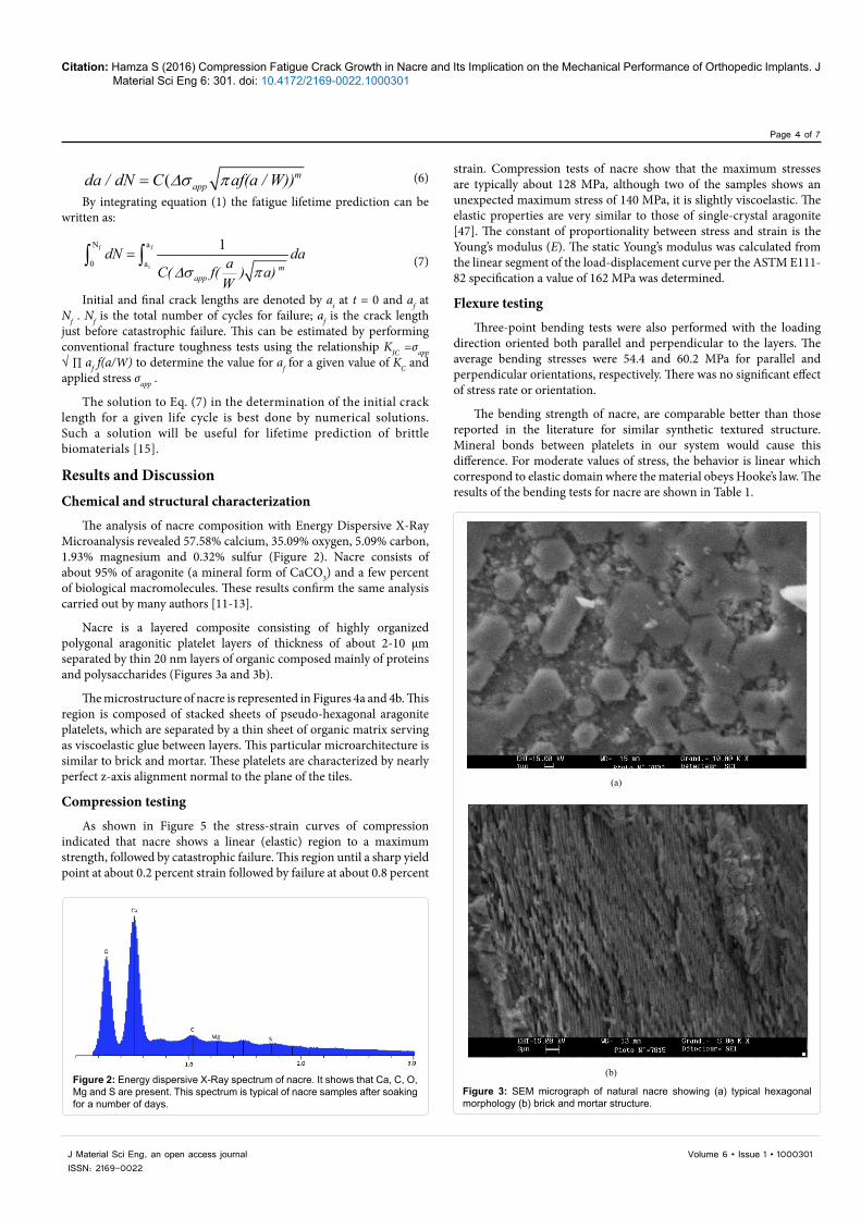
The analysis of nacre composition with Energy Dispersive X-Ray Microanalysis revealed 57.58% calcium, 35.09% oxygen, 5.09% carbon, 1.93% magnesium and 0.32% sulfur (Figure 2). Nacre consists of about 95% of aragonite (a mineral form of CaCO3) and a few percent of biological macromolecules. These results confirm the same analysis carried out by many authors [11-13].
Nacre is a layered composite consisting of highly organized polygonal aragonitic platelet layers of thickness of about 2-10 µm separated by thin 20 nm layers of organic composed mainly of proteins and polysaccharides (Figures 3a and 3b).
The microstructure of nacre is represented in Figures 4a and 4b. This region is composed of stacked sheets of pseudo-hexagonal aragonite platelets, which are separated by a thin sheet of organic matrix serving as viscoelastic glue between layers. This particular microarchitecture is similar to brick and mortar. These platelets are characterized by nearly perfect z-axis alignment normal to the plane of the tiles.
Compression testing
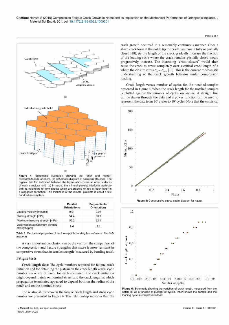
As shown in Figure 5 the stress-strain curves of compression indicated that nacre shows a linear (elastic) region to a maximum strength, followed by catastrophic failure. This region until a sharp yield point at about 0.2 percent strain followed by failure at about 0.8 percent
strain. Compression tests of nacre show that the maximum stresses are typically about 128 MPa, although two of the samples shows an unexpected maximum stress of 140 MPa, it is slightly viscoelastic. The elastic properties are very similar to those of single-crystal aragonite [47]. The constant of proportionality between stress and strain is the Young’s modulus (E). The static Young’s modulus was calculated from the linear segment of the load-displacement curve per the ASTM E111-82 specification a value of 162 MPa was determined.
Flexure testing
Three-point bending tests were also performed with the loading direction oriented both parallel and perpendicular to the layers. The average bending stresses were 54.4 and 60.2 MPa for parallel and perpendicular orientations, respectively. There was no significant effect of stress rate or orientation.
The bending strength of nacre, are comparable better than those reported in the literature for similar synthetic textured structure. Mineral bonds between platelets in our system would cause this difference. For moderate values of stress, the behavior is linear which correspond to elastic domain where the material obeys Hooke’s law. The results of the bending tests for nacre are shown in Table 1.
Figure 2: Energy dispersive X-Ray spectrum of nacre. It shows that Ca, C, O, Mg and S are present. This spectrum is typical of nacre samples after soaking for a number of days.
(a)
(b)
Figure 3: SEM micrograph of natural nacre showing (a) typical hexagonal morphology (b) brick and mortar structure.
Citation: Hamza S (2016) Compression Fatigue Crack Growth in Nacre and Its Implication on the Mechanical Performance of Orthopedic Implants. J Material Sci Eng 6: 301. doi: 10.4172/2169-0022.1000301
Page 5 of 7
Volume 6 • Issue 1 • 1000301J Material Sci Eng, an open access journalISSN: 2169-0022
crack growth occurred in a reasonably continuous manner. Once a sharp crack form at the notch tip the crack can remain fully or partially closed [48]. As the length of the crack gradually increase the fraction of the loading cycle where the crack remains partially closed would progressively increase. The increasing “crack closure” would then cause the crack to arrest completely over a critical crack length of a where the closure stress σcl ≈ σmax [10]. This is the current mechanistic understanding of the crack growth behavior under compression loading.
Crack length versus number of cycles for the notched samples presented in Figure 6. When the crack length for the notched samples is plotted against the number of cycles on log-log. A straight line can be drawn through the data and a power function can be used to represent the data from 103 cycles to 106 cycles. Note that the empirical
A very important conclusion can be drawn from the comparison of the compression and flexure strengths: that nacre is more resistant in compressive stress than in tensile strength (measured by bending tests).
Fatigue tests
Crack length data: The cycle numbers required for fatigue crack initiation and for obtaining the plateau on the crack length versus cycle number curve are different for each specimen. The crack initiation might depend mainly on nominal stress, and the crack length at which propagation terminated appeared to depend both on the radius of the notch and on the nominal stress.
The relationships between the fatigue crack length and stress cycle number are presented in Figure 6. This relationship indicates that the
(a)
(b)
Figure 4: Schematic illustration showing the ‘‘brick and mortar’’ microarchitecture of nacre. (a) Schematic diagram of nacreous structure. The organic thin film indicated between the layers also covers all other surfaces of each structural unit. (b) In nacre, the mineral platelet interlocks perfectly with its neighbors to form sheets which are stacked on top of each other in a staggered formation. The thickness of the mineral platelets is about a few hundred nanometers.
Parallel Orientations
Perpendicular Orientations
Loading Velocity [mm/min] 0.01 0.01Binding strength [mPa] 54.4 60.2Maximum bending strength [mPa] 55.2 62.1Deformation at maximum bending strength [µm] 8.6 9.1
Table 1: Mechanical properties of the three-points bending tests of nacre (Pinctada maxima).
Figure 5: Compressive stress-strain diagram for nacre.
Figure 6: Schematic showing the variation of crack length, measured from the notch-tip, as a function of number of cycles. Insert shows the sample and the loading cycle in compression load.
Citation: Hamza S (2016) Compression Fatigue Crack Growth in Nacre and Its Implication on the Mechanical Performance of Orthopedic Implants. J Material Sci Eng 6: 301. doi: 10.4172/2169-0022.1000301
Page 6 of 7
Volume 6 • Issue 1 • 1000301J Material Sci Eng, an open access journalISSN: 2169-0022
relationships and equations described above are only estimates. The length a data can be plotted using a Basquin’s law type relation determined by a probabilistic approach by using the linear regression, a=B (N)-β where β is the slope of the line. The mean curves are expressed as follows: a=31.79 (N)-0,055 and R2=0.9849 where R2 represents the correlation coefficient.
The results show that growth of damage/cracks at the tip of the notch in a sample of nacre subjected to compression-compression fatigue is highly anisotropic. As a consequence of his the crack and the damage developed in nacre was similar to that observed for bioceramics [41,43].
We observe that the growth if cracks from stress concentrations subjected to cyclic compressive stresses is a mechanical fatigue effect, based on the following observations: Mode I crack advance from stress concentrations, perpendicular to the compression axis in simple of nacre and The crack length increases with an increase in the number of compression cycles.
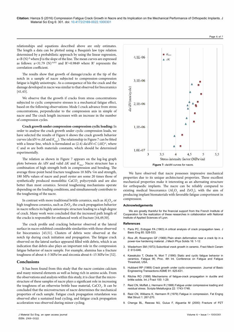
Crack growth under compression-compression cyclic loading: In order to analyse the crack growth under cyclic compression loads, we have selected the results of Figure 6 shows the crack growth behavior curves (da/dN vs ΔK and Kmax). The relationship in Figure 7 can be fitted with a linear line, which is formulated as (2.4) da/dN=C (ΔK)m, where C and m are both materials constants, which should be determined experimentally.
The relation as shown in Figure 7 appears on the log-log graph plots between da /dN and valid ΔK and KMax. Nacre structure has a combination of high strength both in compression and bending. The average three-point bend fracture toughness 10 MPa √m and strength, 180 MPa values of nacre and pearl oyster are some 20 times those of synthetically produced monolithic CaCO3 polycrystals and are also better than most ceramics. Several toughening mechanisms operate depending on the loading conditions, and simultaneously contribute to the toughening of the nacre.
In contrast with more traditional brittle ceramics, such as Al2O3, or high toughness ceramics, such as ZrO2, the crack propagation behavior in nacre reflects its highly anisotropic structure leading to a high degree of crack. Many work were concluded that the increased path length of the cracks is responsible for enhanced work of fracture [44,49,50].
The crack profile and cracking behavior observed at the lateral surface in nacre exhibited considerable similarities with those observed for bioceramics [43,51]. Clusters of debris were observed at the notch tip during crack initiation and propagation. The fatigue crack observed on the lateral surface appeared filled with debris, which is an indication that debris also plays an important role in the compression fatigue behavior of nacre sample. For example, alumina has a fracture toughness of about 4–5 MPa√m and zirconia about 6–15 MPa√m [52].
ConclusionsIt has been found from this study that the nacre contains calcium
and many mineral elements as well as being rich in amino acids. From the observations and analysis within this study, it is clear that the micro-structure of these samples of nacre plays a significant role in increasing the toughness of an otherwise brittle base material, CaCO3. It can be concluded that the microstructure of nacre determines the mechanical properties of each sample. Fatigue crack propagation retardation was observed after a sustained load cycling, and fatigue crack propagation acceleration was observed during minor cycling.
We have observed that nacre possesses impressive mechanical properties due to its unique architectural properties. These excellent mechanical properties make it interesting as an alternating structure for orthopaedic implants. The nacre can be reliably compared to existing medical bioceramics (Al2O3 and ZrO2), with the aim of producing implant biomaterials with favorable fatigue comportment in compression.
Acknowledgements
We are greatly thankful for the financial support from the French Institute of Cooperation for the realization of these researches in collaboration with National Institute of Applied Sciences of Lyon.
References
1. Paris PC, Erdogan FA (1963) A critical analysis of crack propagation laws. J Basic Eng 85: 528-533.
2. Rice JR, Rosengren GF (1968) Plain strain deformation near a crack tip in a power-low hardening material. J Mech Phys Solids 16: 1-12.
3. Wiederhorn SM (1973) Subcritical vravk growth in ceramic. Fract Mech Ceram 2: 613-646.
4. Kawakubo T, Okabe N, Mori T (1990) Static and cyclic fatigue behavior in ceramics. Fatigue 90, Proc. 4th Int. Conference on Fatigue and Fatigue Threshold, USA.
5. Hubbard RP (1969) Crack growth under cyclic-compression. Journal of Basic Engineering Transactions ASME 91: 625-631.
6. Ritchie RO (1998) Mechanisms of fatigue-crack propagation in ductile and brittle solids. Int J Fract 100: 1-29.
7. Reid CN, Moffatt J, Hermann R (1988) Fatigue under compressive loading and residual stress. Scripta Metallurgica 22: 1743-1748.
8. Reid CN, Williams K, Hermann R (1979) Fatigue in compression. Fat Engng Mat Struct 1: 267-270.
9. Chenga BL, Reecea MJ, Guiua F, Algueróa M (2000) Fracture of PZT
Figure 7: da/dN curves for nacre.
Citation: Hamza S (2016) Compression Fatigue Crack Growth in Nacre and Its Implication on the Mechanical Performance of Orthopedic Implants. J Material Sci Eng 6: 301. doi: 10.4172/2169-0022.1000301
Page 7 of 7
Volume 6 • Issue 1 • 1000301J Material Sci Eng, an open access journalISSN: 2169-0022
piezoelectric ceramics under compression-compression loading. Scripta Materialia 42: 353-357.
10. Vasudevan AK, Sadananda AK (2001) Analysis of fatigue crack growth undercompression– compression loading. Int J Fatigue 23: 365-374.
11. Richter BI, Kellner S, Menzel H, Behrens P, Denkena B, et al. (2011) Mechanical characterization of nacre as an ideal-model for innovative new endoprosthesismaterials. Arch Orthop Trauma Surg 131: 191-196.
12. Lin AY, Meyersa MA (2009) Interfacial shear strength in abalone nacre. J Mech Behav Biomed Mater 2: 607-612.
13. Nukala PKVV, Simunovic S (2005) A continuous damage random thresholdsmodel for simulating the fracture behavior of nacre. Biomaterials 26: 6087-6098.
14. Menig R, Meyers MH, Meyers MA, Vecchio KS (2000) Quasi-static and dynamic mechanical response of haliotis rufescens (abalone) shells. Acta materialia 48: 2383-2398.
15. Teoh SH (2000) Fatigue of biomaterials: a review. Int J Fatigue 22: 825-837.
16. Rascona AV, Elguezabalb AA, Orrantiab E, Bocanegra-Bernalb MH (2011) Compressive strength, hardness and fracture toughness of Al2O3 whiskersreinforced ZTA and ATZ nanocomposites: Weibull analysis. Int J Refract Metals Hard Mater 29: 333-340.
17. Sadanandaa K, Sarkara S, Kujawskib D, Vasudevanc AK (2009) A two-parameter analysis of S–N fatigue life using Δσ and σmax. Int J Fatigue 31:1648-1659.
18. Vasudevan AK, Sadananda K, Louat N (1993) Two critical stress intensitiesfor threshold fatigue crack propagation. Scripta Metallurgica et Materialia 28: 65-70.
19. Atlan G, Delattre O, Berland S, LeFaou A, Nabias G, et al. (1999) Interface between bone and nacre implants in sheep. Biomaterials 20: 1017-1022.
20. Vasudevan AK, Sadananda K, Louat N (1992) Reconsideration of fatigue crack closure. Scripta Metallurgica et Materialia 27: 1673-1678.
21. Hamza S, Slimane N, Azari Z, Pluvinage G (2013) Structural and mechanical properties of the coral and nacre and the potentiality of their use as bonesubstitutes. Appl Surf Sci 264: 485-491.
22. Wanga SN, Yan XH, Wang R, Yu DH, Wanga XX ( 2013) A microstructural study of individual nacre tablet of Pinctada maxima. J Struct Biol 183: 404-411.
23. Sunab J, Bhushan B (2012) Hierarchical structure and mechanical properties of nacre: a review. RSC Advances 2: 7601- 7916.
24. Songa F, Sohb AK, Baia YL (2003) Structural and mechanical properties of the organic matrix layers of nacre. Biomaterials 24: 3623-3631.
25. Zhang G, Xu J (2013) From colloidal nanoparticles to a single crystal: New insights into the formation of nacre’s aragonite tablets. J Struct Biol 182: 36-43.
26. Checaa AG, Cartwrightb JHE, Willingerc MG (2011) Mineral bridges in nacre. J Struct Biol 176: 330-339.
27. Heinemanna F, Launspacha M, Griesa K, Fritza M (2011) Gastropod nacre: Structure, properties and growth - Biological, chemical and physical basics.Biophys Chem 153: 126-153.
28. Hamza S, Bouchemi M, Slimane N, Azari Z (2013) Physical and chemical characterization of adsorbed protein onto gold electrode functionalized withTunisian coral and nacre. Mater Sci Eng C 33: 537-542.
29. Meyers MA, Lin AYM, Chen PY, Muyco J (2008) Mechanical strength of abalone nacre: role of the soft organic layer. J Mech Behav Biomed Mater 1: 76-85.
30. Song F, Soh AK, Bai YL (2003) Structural and mechanical properties of theorganic matrix layers of nacre. Biomaterials 24: 3623-3631.
31. Kim YW, Kim JJ, Kim YH, Rho JY (2002) Effects of organic matrix proteins on the interfacial structure at the bone–biocompatible nacre interface in vitro.Biomaterials 23: 2089-2096.
32. Ewart L, Suresh S (1986) New developments in the field of luminescent materials for lighting and displays. J Mater Sci Lett 5: 774.
33. Idem S (1987) Kinetics and mechanism. J Mater Sci 22: 1173-1175.
34. Suresh S, Sylva LA (1986) Use of highly-ordered TiO2 nanotube arrays in dye-sensitized solar cells. Mat Sci Eng 83: 7.
35. Schütz W (1979) The prediction of fatigue life in the crack initiation and propagation stages—a state of the art survey. Engineering fracture mechanics11: 405-421.
36. Lopez E, Vidal B, Berland S, Camprasse S, Camprasse G, et al. (1992) A useful adsorption isotherm. Tissue Cell 24: 667-679.
37. Lopez E, Berland S, Le Faou A (1995) Transparent, conductive grapheneelectrodes for dye-sensitized solar cells. Bull Inst Ocean Monaco 143: 49-57.
38. ASTM E647-00, in Annual Book of ASTM standards (2002) Metals- mechanical testing; elevated and low-temperature tests. Metallography. pp: 595-635.
39. Knott J (1976) Fundamentals of fracture mechanics. Butterworth & Co.(Publishers) Ltd, London, UK.
40. Evans AG, Fuller ER (1974) Fracture toughness and fatigue crack propagation rate of short fiber reinforced epoxy composites for analogue cortical bone. Metall Trans 5: 27-33.
41. Zhan GD, Zhang YZ, Shi JL, Yen TS (1997) Cyclic fatigue-crack propagation in SiC-Whisker-Reinforced Y-TZP composites. J Eur Ceram 17: 1011-1017.
42. Wilson WK (1973) Stress intensity factors for compact specimen used to determine faracture mechanics parameters. Westinghouse Research Laboratories, Pitsburgh.
43. Hamza S, Pluvinage G, Azari J, Gilgert N (2005) Slimane, behaviour ofbioceramic disks submitted to a diametral compressive loading. CaniqueIndustries.
44. Li S, Sun L, Jia W, Wang Z (1995) The Paris law in metals and ceramics. J Mater Sci Lett 14: 1493-1495.
45. Suresh S (1993) In fatigue of materials. Defence Publishers, Belgium.
46. Forman RG, Kearney VE, Engle RM (1967) Numerical analysis of crack propagation in cyclic-loaded structures. Journal of Basic Engineering 89: 459-463.
47. Singh M, Kumar SV, Waghmare SA, Sabale PD (2016) Aragonite–vaterite–calcite: Polymorphs of CaCO 3 in 7th century CE lime plasters of Alampur group of temples, India. Construction and Building Materials 112: 386-397.
48. Elbert W (1976) The significance of fatigue crack closure, ASTP STP 486. American Society for Testing and materials, Philadelphia.
49. Sarikaya M, Gunnison KE, Yasrebi M, Aksay JA (1990) Interpretation of fatigue crack growth in aluminium alloys under programmed block loading. Materials Research Society, Pittsburgh.
50. Waite JH (1992) Results and problems in cell differentiation. Biopolymers 19: 27-53.
51. Changzun Z (1992) Fatigue crack propagation and fractography of 3Y-TZP and ZTA.
52. Li J, Hastings GW (1998) Oxide bioceramics: inert ceramic materials in medicine and dentistry. In: Black J, Hastings G (eds). Hand- book of biomaterials properties. Chapman and Hall, New York.


![FATIGUE CRACK INITIATION AND PROPAGATION IN … Library/101. Fatigue Crack... · 3 or predict fatigue life [15, 20]. In this paper we have conducted a detailed examination of fatigue](https://static.fdocuments.in/doc/165x107/5ab7a8aa7f8b9ad5338bd8f5/fatigue-crack-initiation-and-propagation-in-library101-fatigue-crack3-or.jpg)