Compressed Air Supply - InfoHouseinfohouse.p2ric.org/ref/25/24080.pdf · Single acting compressors...
20
BmKs I TD 4-1R-6 FxEf786 zY%Bo \ P2f TRAINING Compressed Air Supply DIVISION .. . 1. COMPRESSED AIR Compressed air is atmospheric air which has been mechanically forced into a storage chamber under pressure and then, with a means of control, released to perform a specifiC class of work. This atmosphere, the air we breath, consists of approximately 78 percent nitrogen and 21 percent oxygen. Air has weight and this weight'is called atmospheric pressure. At sea level this pressure is 14.7 psi. This means that the air pressure exerted on wry square inch of the earth's surface at sea level is 14.7 psi. This pressure is also exerted to the sides and upwards from the earth; therefore when air is at the compressor intake, it enters with the pressure of 14.7 psi. The atmospheric pressure and density of air decreases as the altitude increases. For example: around Denver, Colorado (6000 8.) the atmospheric pressure is 11.7 psi. Due to the lower pres- sure and lesser density of the air, a smaller (output) quantity of air is delivered by the compressor. Air delivery of a compressor is reduced by approximately 3 percent for every 1000 feet in elevation above sea level. B. Temperature There is an adverse effect on an air compressor's performance when the inlet air temwrature rises above normal. Standard air A. Altitude of the compressor is kept to a minimum. When air is expanded, due to high temperatures, the on-off running cycle will be increased. 0. Cubic feet per minute (C.F.M.) and pounds per square inch (psi) Compressed air is measured on the basis of volume of air used (C.F.M.) at a given pressure (psi). The reference to volume of compressed air is always a measurement of air in its free state; or standard atmospheric condition. The following illustration shows a cubic foot of free air, compared to a cubic foot of air compressed to LOO psi pressure. has been defined as deing 68°F.. having an atmospheric pres- sure of 14.7 psi, and a 36 percent relative humidity. Standard air is used when tests are made and efficiencies computed; stan- dard air is also the basis for rating compressors as to volume delivery capabilities. Should the temperature rise above 68"F., there will be a loss of air delivery equivalent to 2 percent for every 10°F. increase in air temperature. For example: if a com- pressor is operating on a summer day, or in a heated room with an air temperature of 98"F., there would be a 6 percent drop in the volume of air delivered from its rated capability. Therefore, - have the compressor installed in a cool section of the plant or near a window, where good air circulation can be had. C. Heat of Compression Air from the discharge side of a compressor is hot because it has been compressed. The temperature of discharged air ranges hom 150T to 500"F., depending upon the type of compressor sod the working pressure. The higher the working pressure, the pter amount of heat is generated. When this heated air goes into the air receiver we sometimes get a false. reading of the air gauge. As the heat is dissipated from the air receiver, the temperature drops and the pressure will drop even though no air is being used. This is because hot air requires more space and, conversely, cold air, having greater amSi, requires less space. In order to have a "true" volume of air in the storage tank or air receiver, this temperature must be brought to room or surround- ing temperature. This is done by means of an aftercooler. With a "true" volume of air in the receiver, the on-off running cycle Note: As pressure increase, volume decreases.
Transcript of Compressed Air Supply - InfoHouseinfohouse.p2ric.org/ref/25/24080.pdf · Single acting compressors...

BmKs I
TD 4-1R-6
FxEf786 zY%Bo
' \
P 2 f TRAINING Compressed Air Supply DIVISION
!
.. .
1. COMPRESSED AIR Compressed air is atmospheric air which has been mechanically forced into a storage chamber under pressure and then, with a means of control, released to perform a specifiC class of work. This atmosphere, the air we breath, consists of approximately 78 percent nitrogen and 21 percent oxygen. Air has weight and this weight'is called atmospheric pressure. At sea level this pressure is 14.7 psi. This means that the air pressure exerted on wry square inch of the earth's surface at sea level is 14.7 psi. This pressure is also exerted to the sides and upwards from the earth; therefore when air is at the compressor intake, it enters with the pressure of 14.7 psi.
The atmospheric pressure and density of air decreases as the altitude increases. For example: around Denver, Colorado (6000 8.) the atmospheric pressure is 11.7 psi. Due to the lower pres- sure and lesser density of the air, a smaller (output) quantity of air is delivered by the compressor. Air delivery of a compressor is reduced by approximately 3 percent for every 1000 feet in elevation above sea level. B. Temperature There is an adverse effect on an air compressor's performance when the inlet air temwrature rises above normal. Standard air
A. Altitude
of the compressor is kept to a minimum. When air is expanded, due to high temperatures, the on-off running cycle will be increased. 0. Cubic feet per minute (C.F.M.) and pounds per square inch (psi) Compressed air is measured on the basis of volume of air used (C.F.M.) at a given pressure (psi). The reference to volume of compressed air is always a measurement of air in its free state; or standard atmospheric condition. The following illustration shows a cubic foot of free air, compared to a cubic foot of air compressed to L O O psi pressure.
has been defined as deing 68°F.. having an atmospheric pres- sure of 14.7 psi, and a 36 percent relative humidity. Standard air is used when tests are made and efficiencies computed; stan- dard air is also the basis for rating compressors as to volume delivery capabilities. Should the temperature rise above 68"F., there will be a loss of air delivery equivalent to 2 percent for every 10°F. increase in air temperature. For example: if a com- pressor is operating on a summer day, or in a heated room with an air temperature of 98"F., there would be a 6 percent drop in the volume of air delivered from its rated capability. Therefore,
-
have the compressor installed in a cool section of the plant or near a window, where good air circulation can be had. C. Heat of Compression Air from the discharge side of a compressor is hot because it has been compressed. The temperature of discharged air ranges hom 150T to 500"F., depending upon the type of compressor sod the working pressure. The higher the working pressure, the p t e r amount of heat is generated. When this heated air goes into the air receiver we sometimes get a false. reading of the air gauge. As the heat is dissipated from the air receiver, the temperature drops and the pressure will drop even though no air is being used. This is because hot air requires more space and, conversely, cold air, having greater amSi, requires less space. In order to have a "true" volume of air in the storage tank or air receiver, this temperature must be brought to room or surround- ing temperature. This is done by means of an aftercooler. With a "true" volume of air in the receiver, the on-off running cycle
Note: As pressure increase, volume decreases.

When air operated equipment is rated as using IO cfm at 100 psi made of metal or rubber composition. This unit can produce a I ’ I.
it is using 10 cfm of air that has been compressed to 2.46 cubic feet at 100 psi. The equipment is then actually using 2.46 cubic feet of air at 100 psi, however, measurements of its consumption are based on the free air taken into the compressor. The higher the pressure the smaller the cubic foot of air is . pressed to and the more of these blocks of air can pass through an air tool in a given time period. Therefore all air oper-
will still operate the tool adequately and efficiently. Since some pressure is lost when compressed air flows through pipe to the point of use, we must carefully follow recommenda- tions on proper pipe sizes to be used in any plant compressed air systems.
II. GENERAL DESCRIPTION In a compressed air supply system the basic component is the air compressor. This is a mechanical means by which a volume of air is taken from the surounding atmosphere and compressed into a container. Forcing this volume of air into a smaller area creates an increase in pressure above atmospheric (14.7 psi at sea level). The controlled release of compressed air to atmos- pheric pressure permits us to use the resulting pressure drop to do work for us-air power. The amount of compressed air we release to the atmosphere will determine the amount of work that can be performed in a given length of time. Compresxd air is used by many industries in a large variety of applications-one of the major uses is the spray painting indus- try for atomizing materials. Other uses are air-operated tools,
relatively high air output for the motor size. The compressed air delivered is usually oil-free, but not moisture-free, and pres- sures are in the 30-35 psi range. The diaphragms and valves require replacement from time to time depending on use. The housing is die cast forming a unitized construction, both func- tional and aesthetic in design. When started, the unit will run constantly, however, they can he designed for automatic on-off operation. Excessive air pressure is relieved through a built-in unloader valve. This unit cannot start against load-all air must be removed from the compressor before starting. Diaphragm compressors are designed for intermittent opera- tion, lower cost and generally used by the home owner, small painting contractor, or hobbyist. B. Rotary Compressors This type has become very popular during the past few years. They are usually quieter, easier to install, and less expensive than reciprocating types. This design is based on the operating principle of a rotor, fited with vanes eccentrically mounted in a housing. During operation, the vanes are held against the hous- ing by centrifugal force. A lubricating fluid is used in these types for both sealing and cooling. Proper maintenance of the separators in these compressors is very important to prevent excessive carry over of the lubricant into the air system. An absorbent type filter down stream from the unit would be recommended. C. Reciprocatlng Air Compressors This type is the most common compressor. The pressure cham- ber consists of a piston fitted with automotive type piston rings, a cylinder and intake and discharge valve assemblies. Com-
equipment at the lowest possib~e pressure
OIAPHRAGM COMPRESSOR PRESSURE RELIEF VALVE
COMPRESSED AIR, OUT
ATMOSPHER Aln, IN
UPSTROKE-COMPRESSION 61 INTAKE DOWNSTROKE
air control devices, agitating operations, pneumatic water sup- ply systems, temperature and instrument control, fire protection sprinkler systems, liquid or solid transfer by compressed air, and even rodent control. However, here we will focus our atten- tion on compressed air and its use in the spray painting industry. Just as there are many uses for compressed air, there are many types of compressors. Each type of air compressor serves a par- ticular purpose. The following outline will describe a few differ- ent types of compressors, their advantages and limitations. A. Diaphragm Type Alr Compressor-Oil-Free This is a small hand carried compressor for small paint applica- tions. Air pressure is developed through !he reciprocating or oscillating action of a flexible disc. Normally the disc is
pression can take place on either side of the piston or on both sides. When compression takes place on both sides of the piston it is called double acting. For general purposes the single act- ing type is most commonly used. Single acting compressors can be either single stage, or two stage or multi-stage, air or water cooled.
When air is drawn from the atmosphere and compressed to a given pressure in a single stroke, the compressor is a “single stage” unit. Single or multiple cylinders of equal bore size may be employed. These units produce pressure up to 100 psi, some small fractional H.F! units of this type have 150 psi capability. The efficiency of single stage units over 100 psi is very poor. Operation wer 100 psi is usually not recommended.
2

SINGLE STAGE COMPRESSOR
INTAKE VALVE ATMOSPHERIC AIR EXHAUST VALVE
PISTON
J DOWNSTROKE-INTAKE UPSTROKE-COMPRESSION
TWO STAGE COMPRESSOR
When air i s drawn from the atmosphere and first compressed to a intermediate pressure (approximately 40 psi), in the first low pressure stage, then passed through an intercooler to a high pressure cylinder and re-compressed, the air compressor is a "two stage'' unit. The bore sizes of the two cylinders are not the same-the. high pressure cylinder is approximately one half the diameter of the low pressure cylinder. W o stage air compres-
sors are used when air pressure is required in excess of 100 psi and normally not more than 200 psi; this range of pressure is more than adequate for most finishing applications.
Multistage compressors are used when the required discharge pressure is to exceed 200 psi. Multistage units can be designed to produce pressures up to 12,ooO psi.
FlNNEDlNTE
LONG-WEARING. OVER-SIZE. TIMKEN TAPERED ROLLER BEARINGS.
PRECISION BALhNCED PROTECTIVE SCREEN FOR CRANKSHAFT. OIL INLETTO OIL PUMP.
3

111. COMPRESSED AIR SUPPLY SYSTEM The compressed air supply system is designed to provide an adequate supply of compressed air at a predetermined pressure to insure efficient operation of all air-operated equipment. The system can vary in size from a small, hand carried unit to large in-plant installation. The following basic requirements and con- siderations for these systems are the same: I . A compressor, sometimes referred to as a head or pump, can
he one compressor or a series of compressors. 2. The power source can he an electric motor, or possibly a gas
driven uait. The component units can he combined, or mounted indirectly on a common base, or mounted on sepa- rate foundations. Drive connections most commonly em- ployed are. belts and couplings.
3. A control or set of controls regulate the operation of the motor and compressor. a. The control can be a constant speed unloader which
allows the compressor to operate, continuously, maintain- ing a preset pressure without causing the motor to start and stop. This system is generally utilized on portable when compressed air is continuously required by produc- tion equipment.
b. The intermittent type control .is basically a pressure switch and is used on electric stationary compressors. The pressure switch maintains a "cut-in", low prcssure point, for example, 80 psi. When the pressure in the air receiver drops to this low point, the motor will start and the com- pressor will then pump up to its "cut-off" high pressure point which may be 100 psi, thus breaking contact and stopping the motor; when the pressure drops to its low point, the cycle is repeated.
c. There also can he a combination of these controls-con- slant speed unloader and pressure switch. This combina- tion is referred to as dual controls, to be used when air demands vary.
4. Air intake filters or silencers, or a combination of both silencer and filter, are designed to muffle intake noises as well as filter out dust and dirt. The air filter is very important as all air going into the compressor must pass through this filter. The filter element must be made of fine mesh or felt material in order that small particles of grit and abrasive dust do not pass into the cylinders, thus preventing excessive wear on cylinder walls, piston rings, and valves.
5. It is preferable to have a means for cooling the discharged air before it enters the air receiver. The most important common means is a unit known as an aftercooler. An aftercooler can be made in many ways. The most efficient is a water-cooled unit which brings the discharged air temperature down to within a few degrees of the inlet water temperature. An aftercooler is a necessary part of a good compressor system and is the primary requirement for moisture control.
6. The air receiver must be properly sized. It cannot be too small or it will cause the compressor to cycle to often thus causing excessive load on the motor. It should not be too large because of space problems and also unnecessary capacity. On a portable compressor, the air receiver can be relatively small as it acts, primarily, as a pulsating chamber rather than as a storage tank. The Bureau of Standards, Washington D.C., has set stan- dards designating the minimum size of air receiver to be used based on the air displacement rating or the horsepower for any given compressor. This has been accepted by the
A
compressor industry as a standard and is generally followed. When an operation requires a large volume of air for short periods, a large air receiver is frequently used. Using large storage tanks and small compressors is false economy. This combination would require the air compressor to operate for a longer period to maintain adequate volume. Removal of this stored air is very rapid and can result in a temporary shutdown of operations untii the compressor builds up the air receiver to its full capacity. The only working air that is available is what the compressor can produce according to its rated capability The interconnecting piping, that is, the piping between the compressor and the air receiver, can be copper tubing or galvanized iron pipe. If the unit is water-cooled, this will apply to the piping carrying water to the compressor and car- rying water away to the drain, or to the water-cooling tower. The distribution system is the key link in the compressed air system. This is the hose or piping, or arrangement of hose and piping from the air receiver to distribution points requir- ing compressed air. This distribution system consists of the proper sizes of hose or pipe, fittings, valves, air filters, oil and water extractors, regulators, gauges, lubricators and such other items that will provide for the effective and efficient operation of specific air devices, tools, and spraying equipment. a. The proper size of piping as well as the material it is con-
structed of is important. Copper tubing would be the best, then galvanized or black iron pipe. If the compres- sor requires oil for lubrication, the air hose must be oil resistant. The following chart shows the correct pipe size
'
in relation to compressor size and air volume. RECOMMENDED PIPING
Hsr.epo1.r I Lengths I PIPS SIZ.
314 8 1 l'h82 3 8 5 3 8 5 7th 8 10 7th b l a
.... All &I,
upt0200~
up io loa' OVW 200'
100' to 2"
112" 314 314" 1" 314" 1"
7 M 8 1 0 over 200' 1 w 15 6 20 up IO loa' 1" 15 6 20 15 8 20 25 uo 10 2""' , U"
100' 10 200'
~~ ~~ ~ . . . . . ~~
25 I owr2ao' I 1 w
b. These are basic considerations and will have to be mod- ified to accommodate the piping for a compressed air sys- tem in any particular location. At times, a customer may run a compressor in the basement or from a truck and the hose or pipe may go outside and up three or four floors and back into the building. If this were the situation and it was cold outside, then condensation would be a proh- lem, one would have freezing of the hose or pipe. This is inadequate piping even though it may be of the proper size. It is g d praclice if the plant is long and narrow to install an extra air receiver at the far end to act as a cushion and help reduce pressure drop when peak loads are placed on the compressed air supply. Pressure drops, to a great extent, can be avoided hy encircling the plant- or looping the distribution system. This is accomplished hy running the piping in a full circle or loop from the air receiver around the plant and back to the air receiver. A double loop or circle is accomplished by installing a tee in the line and then running a loop or circle in both direc- tions hack to the air receiver. For this type of installation it is recommended that an extra air receiver he installed at the far end to balance out peak loads.

I
Dead End
C
RECEIVER
c. What type of filters, how many, or what regulators should be installed in a compressed air system will depend entirely upon the intended end use of the air power. One installation may be using equipment that requires oil lub- rication for air tools; here then an automatic line lubrica- tor should be installed. In another case, where spraying is done, a lubricator would create a problem. Regulation of air is very important. Less air is consumed when used at low pressure than at high pressures. There- fore, if a tool can be operated at 50 psi and plant air is 80 psi or I00 psi, a regulator should be installed to control the air being supplied and at its lowest operating pressure, consequently using a minimum volume of air and afford- ing lower operating casts. Air line filters or extractors are necessary parts of compressed air supply system. No matter how well the unit is installed there is always the possibility of contamination in air lines. Air filters or extractors of the absorbent type are the best for this pur- pose; however, drops or drop legs can be used.
d. The main discharge pipe (header) leaving the air receiver should be sloped away from the compressor throughout the entire distance it runs, with a drain-off at all low points. The take off from the main header in the air supply system should be from the top of the header. ln- stall a tee in the main header facing upwards with two elbows returning back down toward the floor. This will keep condensed moisture from entering the tool being used. This does not, however, prevent moisture that is not condensed from entering the tool or the line.
THE PROPER METHOD OF REMOVING AIR FROM THE MAIN HEADER
PITCH AWLY FROM COMPRESSOR TO ORAIN I.IN10.
c
IV. CONSIDERATION IN SELECTING AN AIR COMPRESSOR
A. Application First, study the application. Find out what type and how many air consuming devices are currently being used, what the air consumption is for each tool, and what maximum pressures will be required for any one device. Once we know how much air is used under current operating conditions, consideration should be given to provisions for the future addition of air consuming devices. This anticipated requirement should be added to the current system requirement. In addition, a safety factor of a least 25 percent must be allowed to compensate for lowered efficiency, leaks, unforeseen contingencies. Tife total of the above will give us the required capacity to be recommended. Charts are available showing the air consumption and pressure rating for various types of air operated equipment. It is very important that the compressor you select is the correct type and size for your needs. Selector charts No. 1 and No. 2 will help you make the proper choice.
B. Pressure What is the highest pressure required for any ,air device? This will determine whether or not you will require a single stage or two stage compressor.
C. Type of Unit Determine what compressor or compressors are to be recom- mended. One should always consider the possibility of using two compressors, one large or full capacity unit for the normal, full-shift working day and a smaller unit for the second shift or partial working day operation where full capacity is not re- quired. There are also many cases where the total air require- ment is supplied by two compressors; this can assure a constant source of air supply in the case of failure or malfunction of one of the units. In operations where air supply is critical, a com- mon practice is to provide a standby unit and normally, this standby unit is operated alternately on a weekly basis to insure proper functioning and working availability. The combination to be selected is to be determined by an evaluation of the needs and economic factors involved with the proper weight given to each.
D. Controls In order to select and provide the proper type of control equip- ment, a determination has to be made as to the operating cycle of the compressor. This determination will be made by examin- ing the answer to the following questions and then selecting the mode of compressor operation best suited to the intended use. I . Will the air usage requirement be intermittent? Here, an
automatic start-stop control would be best and set so that the operating cycle ratio is approximately 113 running time and 2/3 down time.
2. Will the air usage requirement be fairly constant? Here, a constant service control would be best.
3. Is the air usage pattern a combination of the above, intermit- tent during some periods and c o n s k t at others, so that you have an irregular requirements situation? Then, in such an instance the best answer is to have a dual control-both the automatic start-stop and constant service installation. This permits the user to obtain the best economic advantage in compressor operation in this circumstance.
5

The proper selection should he determined by an analysis of the plant’s mode of operation and anticipated future mod- ifications to such operation. Many times one type of control will he selected for the immediate need with provisions made for the addition of the alternate control.
Here are some additional suggestions: 1, List all of the air operated devices you expect to use from the
compressor with the average free air consumption. (Use Chart No. I for capacities.)
2. Total these free air consumption figures. 3. Note the highest pressure required to operate any tool. 4. For intermittent service refer to Chart No. 2, Column A. For
installations where tools are in constant use, use Column B. a. Determine pressure range needed for operation. b. Within this range, locate total consumption of tools. E. Follow line across to the recommended Binks Compres-
sor Model Number.
Selector ohart no. 1
Type %vice
AirHammer ................ Air Mota (Press. Tank) ....... AirPunrp(Undercoating) . . . . Airless Pumps . . . . . . . . . . . . . . Body Polisher. .............. Body Sander ............... Car Washer.. ............... Dusting Gun (blowgun) . . . . . . Grease Gun (high pressure) . . Pneu. Garage DoM.. ........ Pneumatic Nailers .S Staplers .
tSpray Gun (Siphcn) ......... ?Spray Gun (Siphon) .........
Vacuum Cleaner . . . . . . . . . . . . Spray Gun (Undercoating). ...
100 100 100 100 100 100 100 100 150 150 100 100 100 100 150
d m 16.5 4.0 5.0 6.0 2.0 5.0 8.5 2.5 3.0 2.0 6.0
11 .o 7.5
19.0 6.5
t FwairmnsumpIianafallBInksSprayGuns,seeCaI.956.
E. Volume Check air compressor selected for the actual volume (cfni) de- livered, not for computed compressor displacement. A rule o l thumb for figuring actual cfm delivery at IO0 psi is:
Electric Motor = 4 cfm per horsepower Gas Engine = 2 cfm per horsepower
F. Elevation At what elevation is the compressor to operate? A compressor loses 3 percent in efficiency for every 1000 feet of elevation.
G. Temperature What will the (ambient) surrounding temperature be? The higher the ambient temperature the more moisture the air can contain and iherefore, the less air the compressor will pump. Water-cooled units might be required.
H. Voltage If an electric motor is used, what voltage and phase are required or available? Note: for lowered power cost, motors of 2 h.p. and larger should utilize higher voltages and three-phase current.
1. Location Will the electric motor on the compressor be in a hazardous
location? A special explosion-proof motor is required whenever dust or gas may be present in the environmental atmosphere.
V. ACCESSORY EQUIPMENT
A. Controls-Electrical I . Pressure Switch: controls starting and stopping motor at
set pressure. Wire.d to motor leads between manual starter and motor, or “2-way pilot” device in magnetic starter. When air pressure reaches cut-out point, the contacts in the pressure switch open and stop the motor. Control can be adjusted for various pressures depending upon require- ments. Note: never change the pressure switch without consulting the manufacturer.
2. Ignition Stop Switch: Grounds out ignition current at set pressure, stopping gas engine. Engine must he restarted when required pressure is to be supplied. Contacts work opposite to that of pressure switch.
3. Manual Starter: Usually has start-stop buttons in cover with a reset button under the cover used when the motor has been shut down because of an overload. Used primarily for motor protection, contains thermal overload relays which will open, stopping motor when overloaded or low voltage occurs. Power line goes directly through manual starter, through pressure switch to the motor.
4. Magnetic Starter: A more reliable means for motor protec- tion has a push-button panel to control on-off operation. In this, the power goes through starter direct to the motor, using the pressure switch as a two-pole pilot to activate a magnetic coil which, when energized, causes the contacts to meet, feeding power direct to the motor. This is the best method of motor protection, especially for motors larger than 2 h.p.
5 . Fused Disconnect Switch: This is a knife-type, off-on switch, containing the proper sized fuse. This should he used at or near the compressor unit with the line going from the fused disconnect to the starter. Fuses should he large enough to handle 2% times the current rating stamped on the motor. A qualified electrician should always make the elec- trical hook-up of an air compressor.
6. Controls-Manual I , Loadless Starting Mechanical: This is, in effect, a means of
keeping the compressor from working until the motor can reach its full operating speed, by keeping the starting load of the mntor at its minimum. ~~~~~~~ ~~~ ~
Suction Unloading Valves: Most air compressors use this means to remove the load from the compressor, It merely holds the suction (or intake) valve disc off its seat when starting the compressor so that when air is drawn into the cylinder or on the intake stroke it is exhausted through the open intake valve preventing buildup of pressure in the cylinder and, consequently. the motor does not work during this phase. Diaphragm or Piston Unloader: This is the part which opens and closes the suction valves. It consists of a diaphragm or piston (that comes in contact with com- pressed air) and a linkage or a pin or pins, which operate on the valve disc causing it to open. The air to operate the diaphragm or piston unloader is controlled hy a pilot valve (3-way valve) which in turn is controlled by com- pressor speed, oil pressure, or air pressure.
6

i
! , I
I I i i ~
~ i i h
. .. '?: j ':/
c. 3-Way Valve: We use two typg of 3-way valves. First, on all splash lubricated models, this valve is located d i m l y in the center of the crankcase opposite the pulley side. This valve is normally open when the compressor is run- ning. There is a centrifugal-type governor mechanism built into the crankshaft inside the crankcase. It is not visible and rarely requires any maintenance. sewndly, on pressure lubricated models, the 3-way valve is located slightly off center on the crankcase opposite the pulley side. This differs from the above valve only in the way it is m a t e d . In this case, the oil pressure which is direaed to the back of the 3-way valve, causes the valve to dose or open. When oil pressure is sufficient, the valve will be closed and the compressor operating normally. If the oil pressure drops or when the compressor speed drops to approximately 400 rpm, the valve opens and allows air to reach a diaphragm or piston and the compressor will "unload".
DIAP"RMLI0R PlSTON
DISCWROEVUYE
--PISTMI
URnBETODWFnRIW. ORPlBXxl
DUAL CONTROLS
UNLOADER VALVE
UBINGTOTANK kNKMTG. UNITS
2. Constant Speed Unloader. This device is commonly known as a "pilot-unloader" and is used when it is difficult to start and stop an electric motor or a gas engine. It is a control that works with the suction-unloading valves and the diaphragm unloader to control the pressure of the compressor. When a compressor is operating and reaches the required pressure, the "pilot" opens and allows compressed air to reach the diaphragm, unloading the compressor. The compressor continues to run, but no air is delivered to the tank. This is called "idling". When air is consumed and thereby, the pressure drops approximately 10 psi, the pilot will close and the air over the diaphragm will be exhausted, allowing the compressor to start pumping again'. Constant speed opera- tion should be used when 1/3 or more of the compressor capacity is being used.

Dual Controls. This is a combination of both the loadless stam mechanism (for intermittent operation) and the con- stant speed unloader (for continuous operation). The dual cnntml consists of the elements required for Loadless Starl- ing plus the pilot unloader, a shut-off valve and an air oper- ated check valve. The shut-off valve is installed on the air inlet side of the pilot. The pilot is set to operate at a pressure at least IO psi below the pressure switch setting. When the valve is closed, the compressor will operate through the pressure switch control (intermittent); with the shut-off valve open, the compressor will operate through the pilot unloader (continuous). The user gains benefits from this, he can oper- ate the unit on constant speed when the demand for air is great, and can switch to intermittent service when demand is small or to merely maintain pressure for small jobs. The small additional cost of dual controls is a very worthwhile investment for any customer who may have a fluctuating demand for compressed air. Hand Unloader. Hand unloading is simply taking the load fium a compreswr by manually keeping the intake or suc- tion valve off its seat. The unloading is accomplished by means of a suction unloading valve and a screw-type or lever-type linkage that is operated by hand to force the in- take valve open. This means is used primarily where a compressor is needed only occasionally and is turned on and off by a maintenance man; typical installations being Fire Protection and Water Supply Systems.
5. o&Eng&e Idling Device. This is an air-operated device that, when installed on a gas engine driven compressor, will cause the engine to idle when the compressor reaches its set pressure. As the compressor unloads, the air holding the diaphragm down is also applied to the idler control on the engine. Thc idler control, in turn, pushes against the car- buretor control arm. slowing the engine. When the pressure drops due to pressure being released from the idler control, the compressor staarts to pump increasing the speed of the engine. This device is recommended for use wlth the larger 2 cylinder engines.
C. Safety Accessories 1 A safe& valve is furnished with each compressor unit and is
set to blow before the pressure reaches the rated working prssure of the air receiver. The safety valve is to he tested periodically to make sure it is operating. Note: If it is not operative, or the operation is sluggish, common sense dic- tates that the valve be replaced. Compressed air can be dangerous and its pcwer should be given due respect. A user who attempts to operate a compressor with the safety valve not operating, a defective air receiver, or any malfunctioning control device on the unit can expect to encounter serious cglsequences.
2. &Lt Guard: ’This is a safety device that is legally required in most state. A compressor unit is to be installed in accord with the mzinufacturer’s recommendation that the pulleys face a wall, thereby minimizing any possibility of accidents.
I . Flexible hose connection between air receiver and piping
2. Vibration pads. 3. Intake filters and silencers. 4. Handles and holding brackets for hoisting portable air
D. Mlacellaneous Accessories
system.
compressors.
8
5 . Sewer drain for stationary compressors. 6. Water connections for water-cooled compressors and after-
coolers. ,”..
>> VI. PREVENTIVE MAINTENANCE A. Oil Changes. Follow factory recommendations in chang- ing oil. Most manufacturers require an oil change every 500 hours; sooner if the oil becomes dirty. Use a non-detergent, automotive oil (climatized) or special oil developed for air com- pressors. Oil will deteriorate due to changing temperature and contamination from absorbed dirt. Note: Some small portable units do NOT require oil. 8. Inlet Filters. Dust and dirt entering through the intake can cause considerable damage to valves, rings and cylinders. Fil- ters become clogged and can choke the intake creating an exces- sive vacuum, thus causing “oil pumping”. C. Belt Adjustment. New “V” belts will stretch slightly after about one week of operation. They should be adjusted at that time. Belts should flex about 1/2”. I f they are too tight, and excessive load is placed on both motor and com- pressor main bearings. If they are too loose, they will slip causing them to wear excessively; also, the compressor may run slower resulting in inefficient performance. D. Working Parts. The old adage--“an ounce of prevention is worth a pound of cure”, can be literally interpreted as it applies to maintenance of a compressor system. A periodic inspection of valves, rings, bearings, control mechanism and other parts subject to wear and their replacement where such is needed, can prevent costly breakdown which may occur during critical production periods. E. Distribution System. Small air leaks are costly and unnecessary. A periodic soaping of all connections and the correcting of leaks will guarantee efficient performance from the compressor. F. Clean Air. The use of aftercoolers and proper type filters or extractors is essential in having a clean and dry air system. G. Draining Air Receiver. This may be done by opening the drain valve (daily) on the tank or installing an automatic drain. H. Testing The Air Receiver. Periodic testing of the air receiver is required by many state and local codes. As receivers begin to age, their ability to operate under high pressure loads begins to decrease, therefore, hydrostatic testing to validate the air receiver’s A.S.M.E. label is required.
VII. TROUBLE SHOOTING A. Low Air Pressure. The customer says he does not have enough air or that his pressure is not high enough to operate his equipment properly. The cause can be attributed to one of the following: 1. Insufficient Capacity. Generally one will find that the re-
quirements for air exceed the supply-the compressor does not have sufficient capacity-primarily due to the subsequent addition of air devices. Here the solution is to provide an additional compressor or replace the present unit with one having a larger capacity. Insufficient capacity can be due to a malfunctioning intake valve. A very simple check can be made to determine whether or not the unit is performing properly. First, remove the air filter from the intake on the unit and hold the palm of your hand over the intake hole. If your hand is drawn to the hole and held tight by suction then you may assume the com-

I
i
I
j ~
1 i i i
., ’.
i
pressor is operating satisfactorily. If, however, your hand is not held tight but rather is buffeted back or you can feel a pulsating force on the palm of p u r hand, then the valves in the unit are not seating properly and the :air that is being drawn into the compressor is being blown back out through the discharge, if it is not being compressed through the dis- charged valve into the air receiver. A slight leak in an intake valve can reduce the efficiency. The remedy here is to have the unit repaired.
2. Inadequate Piping. The inside diameter of the pipe is too small to carry the required volume in a given period of time. This can be the main line, branch, or in many cases, the re- stricted flow is caused by the rubber hose extending to the tool. By refehing to air capacity tables or charts for various size hose and pipe, one can determine whether or not a cus- tomer has the proper size of pipe. Compressed air should be delivered to a tool with a minimum of pressure drop. The remedy lies in either increasing the size of the pipe or hose, or if this is impractical, to provide an additional compressor in the a m where difficulty is being encountered. Another remedy would be to “loop” the distribution system, thereby avoiding drastic pressure drops. In this type of distribution system, the addition of a secondary air receiver will insure a better control of line pressure. It is generally recommended that the minimum pipe size to use as a main line should nev- er be less than the size of the compressor discharge opening. FacmrS to consider are how the air is being used, the number of dmp-affs, and whether the air is being used constantly or intermittently. If the shop is large and the main line has a considerable distance to run, a second air receiver installed at the far end of the run would help stabilize pressure. It is sometimes more economical to add an air receiver than to have new piping installed.
3. Air Leakage. A very common source of air loss is found in the distribution system where, due to seasonal temperature changes, the warming and cooling of lines will result in leak- age at various fittings and connectious. Other contributors to air loss are worn out quick change disconnect couplers, leak- ing valves on air devices, open valves (as on drop legs or drain lines), and improper use of air (waste). Leakage in the distribution system can he checked hy the common method of “soaping”. A soapy solution applied with a brush to each joint will indicate whether or not that joint is tight. Programmed maintenance of air devices to replace worn seats, etc., and to replace faulty disconnect couplers will prove to be the most economical solution. Air is not free. A small, continuous leak, say a hole ahout 1/16” dismetercancosttheuser$15.00to $30.00permonth. Pre- ventive maintenance is less expensive.
4. Misuse. By misuse we mean waste. A worker will use his dusting gun to clean off his clothes or cool himself in the summertime or to dust the floor instead of sweeping it with a b m . Another common source of waste is on the drain line or drop leg where the valve has been “cracked” to permit constant draining of condensed water. The remedies for these are obvious: Improved supervisory control of em- ployees, removal of surplus air devices when not in use and provision of an automatic dump valve to control the dis- charge of condensed water.
8. Contamlnation. Another common difficulty encountered in compressed air systems is contamination of air lines. Since
the system is completely sealed and air travels in one direction, a w y from the compressor, it is only reasonable to assume that any foreign matter in the air system has passed through the compressor intake or is the result of something that has passed through the compressor intake. This is the only way air lines in a compressed air system can become contaminated. What causes contamination? The following are typical: 1. Moisture
Moisture causes pipes to rust and, later as it dries, scales are formed which break loose and are carried in the air stream to lodge in a valve seat or plug an air inlet to an air device- resulting in excessive wear or malfunctioning. To remove moisture, air must be cooled below its dew point, preferably before it is discharged into an air receiver. Air when com- pressed is hot, and it is necessary to cool this air, to force condensation so as to trap the resulting water before it enters the compressed air system. The air receiver acts as an initial trap for water, and oil, hut this is not its function; it is an air storage tank. The moisture content of the atmosphere varies with temper- ature. Whatever the moisture content of air is when it enters the compressor intake, the air temperature heiug further raised by the force of compression results in a moisture con- tent transformation to a higher vapor state enabling it to be carried in the air stream without difficulty. As this moistu- rized air travels through the system, the temperature will drop until it reaches room temperature or its dew point, then the moisture in this air condenses and is the source of water in the system. The proper method of controlling this condi- t i o ~ is to use h water-cooled aftercooler. By running cool wa- ter through the aftercooler, reducing the air temperature from about 400 degrees to about 70 degrees, approximately 90 percent of the moisture will be removed and condensed into water. Since water is heavier than air, it will seek the lowest point and here at this point. a trap is installed. If a trap is not used, water will collect in the bottom of the air receiver. If an aftercooler cannot be used and if the distribution lines are long enough to allow the air to cool before being used, then a filter at the far end of the air system would be the next best thing. This filter should have an absorbent element and provisions to collect the water at the bottom of the device.
Another cause of contamination is the presence of oil in the system. Generally, air compressors will have a certain amount of oil vap r present in the discharge air. This is the surplus oil that is not wiped away from the cylinder walls by the piston rings and is carried into the air stream as oil vapor-the high temperature in the cylinder causing the vaporation of oil. As the oil vapor condenses, it combines with the moisture that is present to form a milk-like liquid. One drop of oil can cover an area of approximately 9 square feet of a pan of water-umsid- er the contamination when a piston type compressor uses about one quart of oil for every 4,000,000 cubic feet of air it pumps. This oil when used in a spray gun will mix with coating mate- rials and cause finish failures. Oil is much more difficult to remove than water since oil will creep with the air Row. Oil can be removed only with an absorbent type filter. Passing air through an absorbent filter will remove the oil; when the filter element becomes satu- rated, it must be replaced.
2. Oil
9

An aftercooler will trap a small amount of the oil seeping into the system in its normal Operation. If the compressor is badly worn and an excessive amount of oil is found in the air system,.one will constantly be changing filters. This unit is commonly called an “oil-pumper” and the proper remedy is to overhaul the compressor.
Dirt can be very easily removed with a proper filter on the compressor inlet port. Many filters are available, the most common being the screen type. This type has not proved very effective because it is not being used properly. It is sup- posed to be dipped in oil to give the screen a “tackiness” to catch the dirt particles as they pass through. However, few will maintain this filter in this manner and, therefore. it is seldom used. The majority of installations will provide an oil bath type of filter at the intake port; the air passes through the oil or over the oil, thereby removing the dust or dirt present in the incoming air. This is an effective means for dirt and dust removal. Among other types of dirt filters available, the felt type is used in many installations. Local conditions will dictate the type most suitable for the particu- lar installation.
3. Dirt
VIII. GENERAL NOTES 1. Always fill a new air compressor if required, with standard
automative non-detergent oil having the proper SAE weight or the special oil which has been formulated for air com- pressors. (See low oil pressure item 12a, Page 12.)
2. Keep air compressor as far away as possible from the paint- ing,area.
3. Keep air intake filters clean at all times. If the rmm contains a heavy concentration of dust or has a high humidity, place the air intake outside. If long pipe runs are unavoidable, a rule of thumb is to increase the size of the pipe in the run one pipe size for each eight foot length or run. Provide a large enough filter and a weather shield for an outside intake.
4. If the compressor is not equipped with a loadless starting mechanism, do not start the compressor against a load- first, remove all air from the system.
5 . For an electric motor driven compressor, the voltage, amper- age and proper phase current must be known and available to operate the electric motor. The following may be of some help in determining the proper length of extension cord for small portable electric compressors: 3/4 h.p., 115 volts, single phase requires IO amps while operating and a No. 14 cord for 50 ft. I h.p., 115 volts, single phase requires 15 amps while oper- ating and a No. I2 cord for 50 ft. 1.5 h.p., 115 volts, single phase requires 20 amps while operating and a No. 10 cord for 50 ft. Note: Starting current draw can he three times as high as
the operating current, and fuse protection should be a minimum of two and one-half times the operating current, whenever possible. A rule of thumb for calculating the approximate current consumption of an electric motor for each horsepower of energy delivered: l.h.p., 110 volts, single phase requires 12.8 amps. I h.p., 220 volts, single phase requires 6.4 amps. 1 h.p., 220 volts, three phase requires 3.2 amps. 1 h.p., 440 volts, three phase requires 1.6 amps.
Always operate a motor at the highest voltage possible. Motor larger than 1.5 h.p. should preferably be operated on three phase as the initial cost, as well as operating cost, will be higher for single phase motor exceeding 1.5 h.p. Make sure the motor is connected to the proper voltage and line phase as specified on the motor nameplate.
6. Whenever an extension cord is required, use one having the proper size wire in relation to its length to assure it will carry the load.
I . Always fuse a compressor’s electric supply. 8. Be certain that the electric supply is capable of handling
the compressor’s electrical load. Remove any other elec- trical equipment that may be on the same circuit.
9. Running an air compressor at a pressure higher than its rated capability will lower the air volume output, cause additional wear, and shorten the life of the equipment.
10. Check overload heater elements in magnetic motor start- ers. Heater elements are always stamped with ampere ratings. These should read approximately 5 to 15 percent higher than the full load rating of motor at operating voltage. This full load rating is stamped on the motor nameplate and is also indicated in amperes. Too high a rating of heater elements gives no protection. Too low a rating causes starter to throw-out during starting periods or in hot weather.
I I . The air receiver should be an A.S.M.E. certified vessel. This means that it carries a label certifying that it is con- structed in accord with the A.S.M.E. (American Society of Mechanical Engineers) code for unfired pressure vessels. Most state codes require periodic hydrostatic testing to see that the tanks continue to conform to code requirements. Alternations made to the air receiver in any manner will invalidate the A.S.M.E. certificate and may violate local codes and affect the plant’s insurance coverage.
12. Check direction of rotation. Most air compressors indicate direction of rotation by an arrow on the fly wheel or con- sult the manufacturer’s compressor installation manual. Note: Some units may operate in any direction.
(a.) No oil. (b.) Wrong direction of rotation of the compressor
(c.) Malfunctioning oil pump. 13. Discharge piping must be adequately sized and installed so
as to slope away or toward the compressor. Drains should be provided at low points in the system.
14. Caution is to be exercised in using portable (hand carried) compressors. They have a tendency to “walk” or creep, when in operation and care should be taken in their place- ment. In all instances, it is recommended that the unit be securely anchored, especially if placed in overhead loca- tions or where damage is possible if the unit should c m p .
15. Install a sewer drain in the floor of a compressor room for the removal of condensed water from the air receiver or aftercooler.
16. Read all instructions pertaining to the air compressor and the related equipment before operating the unit. Additional information can be obtained from the equipment manufac- turers. For information on the installation and trouble shooting of Bink’s air compressors, see Part Sheet 1767.
12a. Low oil pressure can be caused hy one of the following:
fly-wheel.
10

IX. THERMAL CONDITIONING AND PURIFICATION EQUIPMENT A. General The removal of contaminants from compressed air is important in the interest of safety and protcction against damage to air tools, materials. and products. It is important that compressed air be cooled, dried, and cleaned before it is distributed for use. I . When air is compressed it becomes very hot, and in this
condition, it is a potential explosive. Danger of a combus- tion explosion, in either the air receiver or pipe lines, is always present i f the air is not sufficiently cooled after leaving the compressor. Heaced air will result in less air king stored in the receiv- er. hold more water and cause the pipe lines to expand with subsequent contraction when the conipressor is shut down and the pipes cool. This cooling will cause con- densation and the alternate lengthening of the lines u l t i - mately produces leaky joints.
2. The air in the atmosphere is never really dry. Water in a vaporized condition is always present, the amount before cadensation wcurs is in d i m proportion to the tempera- ture of the air and inversely proportionate to the pressure. I n other words, the hotter the air, the more moisture it can hold in vapor form; the greater the pressure, the less water vapor it can hold. A change in either pressure or temperature up- yts Ihe equilibrium of water vapor filled air. If the air pres- sure increases and the temperature remains constant. air loser its ability to hold water and condensation lakes place. This is the process which creates rain, or water accumulation in air receivers. pipes. and water extractors Compressed air becomes cooler as it approaches the end of the line. In cooling, ~t loses its capability for carrying moi5- NTC in vapor form and thereby the moisture is condensed and discharged in liquid form (water). Sudden expansion of compressed air at the point of discharge causes rapid cooling (icing). The water vapor in the air is then further condcnsrd and carried through the air device and discharged into the atmosphere. or in many instances discharged onto the uork or procss being performed. In pneumatically operated machines, this releare of wdter re- moves lubricating oil resulting in equipment inefficiency and deterioration. It may cause excessive wear on valves. fault) operation of air controlled equipment. rust, corrosion, f i n k h failure and if there is a possibility of line freezing, the ac- cumuhtion of water in low points in the distrihution system may result in bursted pipes.
3. Vaporized oil can present operating and maintenance prob- lems. Too high a temperature and excessive oil vapor in n critical mixture with air can result in a combustion explo- sion. Adherence to safety procedures and proper mainte- nance of control equipment is paramount. Oil should be re- moved before it enters the distribution system: once there it will creep through and most likely contaminate the product or process. Oil is introduced into the air supply because of compressor wear or it5 high operating temprrature. Note: This problem is not present in the oil-less type compressor.
4. If solid panicles or other impurities, such as ru\t, dust, so- vent vapors, overspray, etc. are present in the immediate atmasphere, these mdy be drawn through the compressor in - takes and find their way into the air dimihution
’?
system. The impurities entering a compressor will contrib- ute to excessive wear and premature parts replacement, de- crease efficiency, deteriorate air devices and in cases such as finishing, affect the quality of the finish. If rust is present in the discharged air, it indicates that the pipes or receiver are rusted, or that somewhere in the system a unit has been in- stalled that is constructed of incorrect material.
6. Aftercoolers The primary consideration is to reduce the temperature of compressed air. Heat, as well as some impurities, can be re- moved by installing an aftercooler in the system. Aftercoolers are very efficient in lowering air temperature and removing most of the oil and water; the residue of oil and water will be removed before it enters the air receiver. There are several different designs or types of aftercoolers available. The most common is the water-cooled “air tube” design in which air passes through small tubes and re-circulating water is directed back and forth across the tubes by means of baffles and moves in a direction counter to the flow of air. This cross-flow prin- ciple is accepted as the most efficient means of heat transfer. The air is cooled to within 15” of the incoming city water temperature, using approximately I ‘h gallons of water for each 100 cubit feet of compressed air passing through the unit. For example, on a 5 h.p. unit with 19 cubic feet capac- ity, a cooler would use l‘h gallons of water for each 5 min- utes that the compressor was actually pumping. The water flow is controlled by a solenoid operated water controlled valve which operates only when the compressor is running. If the compressor is operating with a constant speed unloader, then an air operated water control should be installed. Oil and water leave the aftercooler in a liquid state, being con- densed by cooling. It is either directed to flow back into the air receiver or to a moisture and oil separator which can be automatically or manually drained. The aftercooler is an essential part of a complete and properly functioning compressed air supply system. The larger the air compressor and the higher the operating pressure. the greater the need for an aftercooler. 1. Consideration in selecting aftercoolers are:
a. The maximum volume of air the aftercooler must handle. b. The maximum working pressure of the aftercooler. c. The required temperature drop for the compressed air
d. The availability of an incoming cold water supply and
e. The size of the pipe connections at the aftercooler for
f. The means for removing condensed oil and water from
supply.
its temperature.
the inlet and outlet of both air and water supply.
the system.
I WATER OUT 19
WARM COOL AIR AIR IN OUT
1 WATER IN
Water-cooled aftercooler
11

C. Automatic Dump Trap This trap, installed at the lowest point below the air receiver, will collect condensed moisture. It is so designed that the trap opens automatically to discharge a pre-determined volume. Due to the air pressure behind the water, the trap opens and closes with a snap-action that insures proper seating of the closing valve. A small line strainer should be installed ahead of any automatic device to keep foreign particles from clog- ging the working parts. If this uni t is properly installed, with a line strainer. it will give long and satisfactory service with minimum maintenance.
D. Air Dryers Good aftercoolers will remove the greatest percentage of wa- ter vapor but the residue can still cause problems. For exam- ple, if 10 cubic feet of free air holds I oz. of water per cubic foot and this volume is compressed into I cubic foot, at a higher pressure and temperature the moisture that was in the IO cubic feet will be contained in the 1 cubic foot volume in the form of water vapor as long as the temperature remains elevated. When the air cools down to its original incoming temperature (into the compressor), all the water vapor will condense except for that amount that was in the original cubic foot volume of free air. This will condense out somewhere in your distribution system or he carried into your air tools or finished product. There are many designs of air dryers available; among these the most common are chemical, desiccant and refrigeration types. All dryers are designed to remove moisture from the compressed air supply so that no condensation will take place in the distribution system under normal working conditions. 1. Chemical Dryers (deliquescent, dehydrator type)
Chemical dryers operate on the principle that certain chem- icals will react with moisture, forming a solution which will drain to the boltom of the dryer and be removed. The chem-
8 = i o Cubic feel 01 air mmprersed lo 1 cubicfaat.
icals used in the operation have to be replaced as they are consumed in the process. The chemical can be salt o r a specially formulated material, a soluble chemical desiccant which is more efficient than salt and is non-corrosive and non-toxic. Most air dryers “scrub” the air three times: First, by the mechanical separator; second, by the misting system; and third, hy the soluble chemical desiccant. The path that air blows through a chemical dryer is as follows: a. Mechanically-the entering air stream passes through a
nozzle which atomizes the moisture drippings from the desiccant chamber. The air stream is then reversed in direction, causing condensation (free water) to he thrown clear, collecting in the bottom of the unit for automatic or manual discharge. Desiccant mist pre-dries the air. Droplets from the des- iccant bed are a mild chemical solution, created by moisture vapors slowly dissolving the desiccant beads. Atomization of the droplets by the entering air stream creates a fog-like mixture, each particle still retaining an affinity for moisture. This results in about 60% of the water vapor being removed prior to the air stream’s contact with the desiccant bed, minimizing the usage of the raw desiccant beads.
AIR SUPPLY LINE
$ 8 I,
I, , #
12
b. Chemically-the air stream then enters the desiccant bed by means of stainless steel diffuser baffle which distrib- utes the air uniformly. The remaining 40% of water vapor is chemically attracted out of the air providing the dis- charged air with a dew point below 0°F. depending on
( I ) Considerations in selecting an air dryer: -volume of air the unit can dry. -maximum working pressure of the unit; the high-
er the working pressure the more efficient. -inlet and outlet pipe sizes as well as their loca-
tion. -temperature of the air entering the unit. Efficien-
cy of the unit increases as the temperature drops below 90°F. The materials will dissolve without the presence of water.
Most desiccants cease to function efficiently at temperatures above 120°F and some can break down chemically and add toxic and corrosive compounds to the air supply system. The best possible location for the air dryer in the air supply sys- tem is between the aftercooler and air storage receiver. This way, the air dryer can be sized according to the compressor's output; and always be at the highest possible pressure. However, a very efficient aftercooler must be employed with this design as the air temperature will also be at its highest possible point. Installing the dryer down stream from the air storage tank is possible as long as the dryer is selected to accommodate the maximum possible air demand at any one time.
(2) Advantages of an air dryer: -eliminates maintenance of numerow 'water traps. -decreases maintenance of all pneumatic equip-
ment such as air tools, cylinders, valves, spray guns, pumps, hoists, etc.
-decreases product rejects in finishing departments due to contamination by dirt, oil or water.
-increases production by eliminating down time for maintenance.
-the air will be non-toxic and sterile; safe for hu- man consumption. Suitable for use in the food processing industry.
."p !, operating conditions.
(3) Limitations -new chemicals must be added to maintain proper
-moisture will not he removed if the dew point is operating levels.
below -2OT. 2. Desiccant Type Dryers
Air is passed thmugh a desiccant contained in one or more tanks. As the moisture laden air passes through the des- iccant, it is absorbed by the chemical as a sponge absorbs water. When the desiccant in one tank becomes saturated with wa- ter, the air is directed to another tank or the operation can be dosed down, Water which has been absorbed is driven out of the desiccant by heat or other means. These systems work efficiently at low temperatures and will produce air with a dew point below that of chemical dryers.
Desiccant dryer " 3. Refrigeration Air Dryers
A mechanical refrigeration system cools the heat exchanger by chilling the air to a temperature below the minimum temperature that is attainable in the distribution system. As long as the temperature in the system remains above the dryer temperature, the conditions for the formation of con- densation do not exist.
AIR IN
Refrigerated dryer
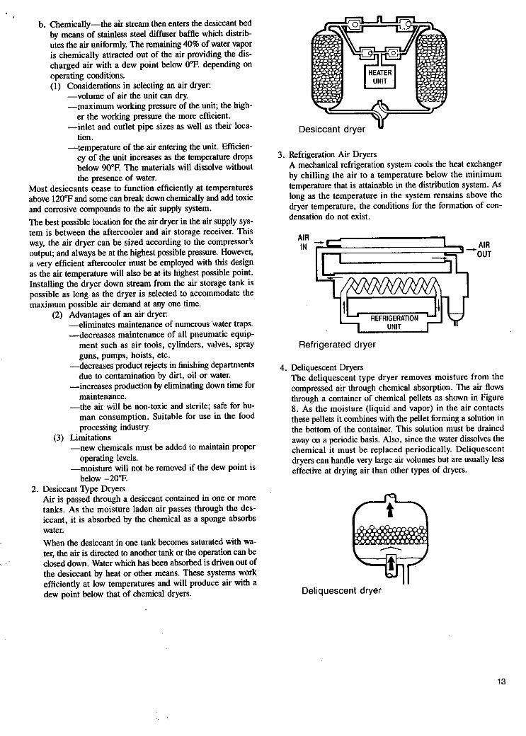
4. Deliquescent Dryers The deliquescent type dryer removes moisture from the compressed air through chemical absorption. The air Rows through a container of chemical pellets as shown in Figure 8. As the moisture (liquid and vapor) in the air contacts these pellets it combines with the pellet forming a solution in the bottom of the container. This solution must be drained away on a periodic basis. Also, since the water dissolves the chemical it must be replaced periodically. Deliquescent dryers can handle very large air volumes but are usually less effective at drying air than other types of dryers.
Deliquescent dryer
13

5. Line. Filters or Oil and Water Extractors A line filter is to be installed at any point in the distri- bution lines where air must be dry and oil-free. This is mandatory if a compressed air system is used without an aftercooler. The best type line filter is the absorbent type where air passes through an element of some material that will absorb water and oil particles. Remember that water always seeks a low point, whereas oil particles are carried with the air. Some oil and water extractors are combination filter- regulators and are convenient where pressure regulation is necessary.. Where pressure regulation is not necessary, main Line extractors are not only sufficient, but better than most line filters. The primary reason for this is that oil and water extractors are made of noncorrosive materials and their Life exceeds that of any steel or iron filters. These oil and water extractors are installed in the air dis- tribution system after the air receiver. The proper distance should be at least 25 feet away from the air receiver so that the sir has a chance to cool down sufficiently before reaching the extractor. They are an effective means for re- moval of *e impurities normally found in the majority of air distribution systems. An extractor’s efficiency is vari- able and is related to the temperature and humidity of the compressed air. These units d o not provide results as effectively as air dryers, however, their lower initial cost is a factor in selection of alternative means. One unit will be required at each take-off point on the main line (header).
Operation: The ‘following briefly describes operational characteristics of common types of extractors: a. Baffle plates are used to force the air stream to change
direction very rapidly causing the heavier dirt particles to be dislodged and carried along the side walls to the bottom of the extractor. Others incorporate a lead screw principle which creates a cyclonic effect or a whirlwind type of air movement. This motion causes the heavier particles to be dislodged against the inside walls of the unit.
b. Another method is to have the air strike the cooler walls of the extractor’s outer body. This in combination with the pressure drop resulting from air being used will cause water to condense out of the air.
c. Filters are employed to trap solid particles as well as absorb moisture. Some of the different types of filters available are: -porous or sintered bronze -metal or plastic cylinders -high absorbent cloth -water absorbent chemicals
Seiectlon Considerations: a. Volume of air that the extractor will be required to clean. b. Maximum working pressure on the extractor. c. Method of filtration and water extraction. d. Piping inlet and outlet size. e. Distance for the compressor to the extractor. Note the
minimum recommended distance is 25 feet. The piping should slope toward the compressor for best results.
Maintenance: The following are the requirements of a basic maintenance program:
14
a. Oil and water extractors must be drained daily, under pressure, to remove impurities. If the conditions are ex- tremely severe, they may have to be drained periodically during the day
b. Extractors having filters must be disassembled and the filter element cleaned or replaced; otherwise the amount of air passing through the unit will be appreciably reduced.
c. Maintenance schedules should be established to clean, drain and replace filters at periodic intervals.
d. It is good practice to keep spare air seals for oil and water extractors on hand.
’
Oil and Water Exlnctor
E. Filters Filters are normally a mechanical means by which solid parti- cles are removed from the air supply. Filter units normally do not remove moisture as it is a water vapor (gaseous) form and will pass through with the air stream. The principle function of a filter is to remove the solid particles out of the air stream that may cause a malfunction of an air device or may damage the equipment. 1, Selection Considerations:
a. The volume of air required to flow through. b. The maximum working pressure. c. Inlet and outlet piping size. d. Materials of construction-corrosion resistant, etc. e. Size of filter element-this will determine how often it
has to be cleaned or replaced. f. The smallest size particle it will filter out (retain).
a. Will filter out solids to a fine degree depending o?
b. Low cost. c. Easy maintenance.
a. Element must he cleaned as conditions require, other-
2. Advantages:
screen mesh selected.
3. Limitations:
wise efficiency and air flow will decrease.

TYPICAL OIL & WATER EXTRACTORS, COALESCERS, AND AIR DRYERS
CONDITION INDICATOR BRACKET
HEAD
TIE ROD
FILTER
TUBE
RETAINER
SEAL NUT STEM
EXTRACTOR COALESCER
X. AIR REGULATORS
A. General Description An air regulator is a mechanical device which reduces the main line air pressure to a specific operating pressure. Once the oper- ating pressure is set, the regulator will automatically maintain this setting. For example: if a 100 psi main line supply of air is to he reduced to an operating pressure of 40 psi, then the air regulator will have to be set to create a 60 psi drop in the sys- tem. If the 100 psi supply changes, the regulator will automati- cally compensate for this change. Once the regulators are set, any reduction in pressure will cause the regulator to pass more air; if the pressure increases, the regulator will pass less air. The pressure set in the regulator will always be constant irrespective of the main line fluctuation. A regulator will NEVER provide higher air pressure than the air distribution system has to offer. The following describes the sequence of operation: -by turning the control knob in a clockwise direction, the con-
-the button pushes against the regulating spring (pre-loaded). -the valve stem, in turn, moves the valve away from its seat. -air flows by the seat into the regulated outlet. -air pressure on the regulated side increases, this pressure
pushes against the diaphragm and regulating spring. -when the air on the regulated side is balanced, it then reacts
against the diaphragm and regulating spring causing the valve to return to its seat (closed).
-as air is consumed from the regulated side, the resultant pressure drop will create an unbalance of forces (air pressure) against the diaphragm and the spring causing the valve to un- seat and, again, pass that amount of air needed to balance the system.
I
trol knob screw will push a button.
DRYER
B. Types Air regulators are designed in two different styles. The mechan- ical parts of each are the same, the difference being in the way the body has been drilled. The first and most common style is referred to as a standard regulator. Standard regulators are usually used on oil and water extractor regulator combinations or as the second regulator on a pressure tank. The second style is referred to as a by-pass regulator which has two regulated outlets and a by-pass for passing main line pres- sure. By-pass regulators are usually employed as the first regu- lator on pressure tanks, when manifolding regulators together or even used as take-offs from main air supply lines. By-pass regulators may be identified by introducing air into the inlet port as marked and observing if the air passes through without air regulation taking place.
C. Selection Consideratlon 1. the need for a standard or by-pass regulator. 2. the volume of air the regulator will be required to handle.
Note: to provide for future needs, always select a regulator having a capacity about 125% of your current determined volume.
3. the highest operating pressure the regulator must control. 4. the proper size of gauge required for the regulator. 5. the size of pipe connections of inlets and outlets.
D. Trouble Shooting I . See part sheet pertaining to your specific regulator
15

2. Problem: air leaks out of hole in top of bonnet. Remedy: tighten screws on bonnet flange. If this does not stop the leak, it is likely that the diaphragm has been punctured.
Remedy: clean seat and stem or replace with new pans.
Remedy: spring returning the valve stem is rusted or valve stem is held fast by corrosion; clean parts affected or re- place as required.
Remedy: tighten scews on bonnet flange, replace gasket or add a second gasket on the other side of the diaphragm.
Remedy: make sure air supply is turned on; check to see if air passes freely through oil and water extractor; see that air is reaching the air regulator; inspect regulator filter screen; clean all air passageways in regulator; replace or clean regulator filter screen if required.
3. Problem: regulator gauge climbs to main Line pressure.
4. Problem: regulator will not regulate the pressure.
5 . Problem: regulator sings or hums.
6. Problem: no air passing through regulator.
- SPRING
XI. AIR LINE LUBRICATORS A. General Descrlption The detrimental effect of oil in an air line system has been stressed repeatedly throughout this Training Bulletin. However, there are instances when a proper amount of oil correctly atom- ized is essential to the operation of certain types of air tools or air operated devices. Introduction of this essential lubricant pre- vents corrosion, seizing of close tolerance bearing surfaces, and maintains the resilience of “0” rings and seals. For this purpose lubricators can be mounted on or at the operat- ing device, built into the device (many air tools have this fea- ture), or be installed in the air stream just upstream of the inlet to the air tool. Once lubricators are installed and the proper level of lubrication is maintained, they will provide automatic lubrication to the equipment.
:..
E. Selection Consideration 1. type required for the application. 2. volume of air the unit must pass. 3. amount of lubricant required. 4. working pressure of the unit. 5 . pipe inlet and outlet size. 6. quantity of oil in the lubricator’s reservoir. I. type of lubricant required.
1. the equipment requiring a lubricant will receive the cor- rect amount and type.
2. minimizes tool repair. 3. better ooeratine efficiencv.
C. Advantages
GASKET
D.
- 4. tools and other air operated devices may be stored and
subsequently used without concern as to oil sludge being created in the tool.
5 . lubricants are fed into the equipment only when unit is operating.
, Limitations 1. it is additional piece of equipment that requires main- . .
tenance. 2. adds different weight oils to specific types of air operated
tools. 3. not all types of lubricant can be used. 4. reservoirs may require frequent filling when lubricant . . -
A SPRING requirements are high. E. Precautionary Notes
AIR REGULATOR 1. Using a multi-tool lubricator there is always the danger that the unit may run dry and damage to the tools using the same system. Lubricating-maintenance of the oil level in such instances-is of prime concern.
2. Keep air Lines short; oil sludge may accumulate in low spots of long air lines.
16

4.
5 .
S i e types of lubricant should not be used as these oils will create paint finishing problems. Other types of lubri- can@ such as moly-graphite, sewing machine or 3-in-I oil ” i n additives which map damage certain types of seals and surfaces. It is recommended that a standard non- detfzgent antomotive oil or the special oil developed for air “Is he used. To function properly, lubricators must be matched to the equipment’s needs. The proper amount of lubricant is important as too much as well as too tittle can create problems. A good rule is to ad- just the lubricant feed until a small amount of oil is percepti- ble at the exhaust p r t of the tool. An over supply of oil has a tendency to create an “oil fog” which can be objectionable to people working in close proximity.
XII. GLOSSARY OF TERMS FOR COMPRESSED AIR SUPPLY SYSTEM ABSOLUTE PRESSURE is the existing atmospheric gauge pressure plus atmospheric pressure. At sea level the gauge pres- sure in pounds per square inch plus 14.7 psi gives the absolute pressure in pounds per square inch. ACTUAL CAPACITY of an air o r gas compressor is the quantity of air or gas compressed and delivered. It is usually expressed in cubic feet per minute (CFM) at intake pressure ani temperature. AFTERCOOLERS are devices for removing the heat of com- pression of the air or gas after compression is completed. They are one of the most effective means of removing moisture from compressed air. AIR RECEIVERS are tanks into which compressed air or gas is discharged for the compressor. Receivers help eliminate pulsations in the discharge tine and also act as storage capacity durina intervals when the demand exceeds the caoacitv of the - . . -. COMPRESSORS are machines designed for compressing air or gas from an initial intake pressure to a higher discharge prssUre. COMPRESSION EFFICIENCY is the ratio of the theoretical horsepower to the actual indicated horsepower required to com- press a definite amount of gas. The theoretical power may be calculated according to the isothermal base or the adiabatic base and the compression efficiency correspondingly defined and expressed in per cent. DISPLACEMENT OF A COMPRESSOR CYLINDER is the wlume swept through by the piston, with proper deduction for the piston rod. This is usually expressed in cubic feet per minute. DISPLACEMENT OF A MULTI-STAGE COMPRESSOR is that of the first stage only, since the same gas passes through a l l stages in series. DOUBLE ACTING COMPRESSORS are those in which compression takes place on both strokes per revolution in each ompressing element. FREE AIR is air at normal atmospheric conditions. Because the altitude, barometer and temperalure vary at different locali- ties and at different times, it follows that this term does not mean air under identical conditions. Considerable confusion has existed regarding the term “free air” and it has often been in- kerpreted to be air at sea level conditions, namely at an ahsolute pressure of 14.7 psi and at a temperature of 68°F. This is not the
correct interpretation of the expression of “free air”, and in this TD Bulletin the term means air at the atmospheric conditions at the point where the compressor is installed. HORIZONTAL COMPRESSORS have the compressing element in a horizontal plane. INTERCOOLERS are devices for removing the heat of com- pression of the air or gas between consecutive stages of multi- stage compressors. LOAD FACTOR is the ratio for the average compressor output during a certain period of time to the maximum rated output of the machine. LOW PRESSURE ORIFICE TEST is a method of accurately measuring the air delivered by a compressor. It is the method recognized by the Compressed Air Institute. MECHANICAL EFFICIENCY is the ratio of the indicated horsepower in the compressing cylinders to the indicated horse- F e r in the power cylinders, in the case of steam driven or in- ternal combustion engine driven compressors and to the break horsepower delivered to the shaft in case of a power driven machine. It is expressed in per cent. MOISTURE SEPARATORS are devices for collecting and removing moisture precipitated from the air or gas during the process of cooling. MULTI-STAGES COMPRESSORS are those in which com- pression from initial to final pressure is completed in two or more distinct steps or stages. NORMAL AIR has heen variously defined. In this hook the term refers to air with a 36% relative humidity at 68°F. This may he considered an average condition of the atmosphere in a temperate climate. The ratio of specific heats or “n” is 1.3947 for normal air. Density is ,075 Ihs./ft.’ at 14.7 Ibs./in.’and 68°F. OVERALL EFFICIENCY is the product of the compression efficiency and the mechanical efficiency, PORTABLE COMPRESSORS are those in which each com- pressing element consists of a piston moving hack and forth in a cylinder. ROTARY COMPRESSORS are those having a vane rotor or its cquivalent mounted eccentrically in 3 stationary caung. SINGLE-ACTING COMPRESSORS are those i n which compression vikcs place on hut one stroke p a revdution in each compressing element SINGLE STAGE COMPRESSORS are tho\e in uliish com- presbion froni initial to l i n d prewre ic complete in a single step or stage. TWO STAGE COMPRESSORS arc those in which coiii- pression from initial to final pressure I, completed in two dib- tinct step, or stage,. VALVES are classified in tu’o di>tinct types. Mechanically operated valves depend for their opcning and closing otn wmc external, mechanical means. They are usually driven from the crank shaft Their time of opening and closing is tixed in rela- tion to the movement of the pibton. Automatic valves depend for their opening and closing entirely on pressurc differences. In the case of the inlet valve, between intake 3nd cylinder pressures and in the case of the discharge valvc. between cylinder and discharge pressures. VERTICAL COMPRESSORS have the compressing element - in a vertical plane. VOLUMETRIC EFFICIENCY is the ratio of the actual capacity of the compressor to displacement and is expressed in per cent.
17

XIII. HOW MUCH DOES AN AIR LEAK COST?
HP KWH LEAKID SCFM (inches)
1 I64 3 6 .09 .07 1/32 1.47 37 30 3/64 3.28 .82 .66 1/16 5.87 1.47 1.18
3/32 13.10 3.28 2.62
118 25.80 6.45 5.16
311 6 58.30 14.58 11.66
114 103.00 25.75 20.68
Based on 90 psi, 8e'per KWH. two 8 hour shifts, 5 days per week. *An arbitrary cost which varies with time & place.
$/DAY
.09
.38
.85 1.51
3.35
6.60
14.92
26.47
$/Motan
1.95 8.23
18.42 32.72 72.58
143.00
323.00
574.00
$NEAR
23.40 98.76
221 .oo 393.00 871 .OO
1716.00
3876.00
6888.00
18

Notes
19

1 . A,!"
spray equipment needs. They await your inquiry and are prepared to add their years of experience to the information supplied in
A comprehensive network of select jobber specialists stamls ready to take care of your
this literature.
Branch Offices With Warehouse Facilities Atlanta, GA
Chicago, IL
5575 Spalding Or.. Norcross, GA 30092-2559
9201 Belmonl Avenue. Franklin Park. lL60131-2887
FAX4041368-9411 ..................................... 4041447-5600
FAX 7081671-1471 ..................................... 7081671-3000 Cleveland, OH
15401 Commerce Park Or., Cleveland, OH 44142-2012 FAX2161362-0114 . . . . . . . . . . . . . . . . . . . . . . . . . . . . . . . . . . . . 2161362-8500
Dallas.TX 14340 Proton Rd.. Farmers Branch, TX 75244-3594 FAX 2141702-9502 ..................................... 2141233-2500
Detroit. MI 11996Merriman Rd., Livonia. MI 48150-1991 FAX3131525-6917 .........................
Lo9 Angelea. CA
Mllwaukee. WI
1405 Pioneer Street, Brea, CA92621-3721 FAX 3101691.2988 . . . . . . . . . . . . . . . . . . . . . . . . .
12705 Robin Ln.. Brookfield. WI 53005-3125 FAX 4141781-6854 .........................
Service.. . Where you want it, when you need it.
New York, NY 1 Chapin Ad.. Pine Brook, NJ 07058-9719 FAX2011575-4034.. . . . . . . . . TELEX 133325.. . . . . . . . . 201 1575-6660
4301 Rising Suo Ave.. Philadelphia. PA 19140-2719 FAX 2151456-1210 . . . . . . . . . . . . . . . . . . . . . . . . . . . . . . . . . . 21 51329-7800
Pillsburgh Spray Equipmenl Ca. 3601 Library Rd., Pittsburgh, PA 15234-2230 FAX4121882-8281.. . . . . . . . . . . . . . . . . . . . . . . . . . . . . . . . . 4121682-4550
Phllsdelphls, PA
Pittsburgh. PA
San Francisco, CA 1459 Sa" Maleo Ave., South San Francisco. CA 94080-6572 FAX4151589-3151 .................................. 4151589.8477
3131525-6900
. . . . . . . . . . . . 3101691-1900 Seat tkwA 1749 First Ave., S.. Seafile. WA98134-1441 Po. Box24706. Seattle. ~ ~ 9 8 1 2 4 - 0 7 0 6 FAX 2061623-4179. . . . . . . . . . . . . . . . . . . . . . . . . . . . . . . . . . ,206323-1350 . . . . . . . . . . . . 4141781-6880
Branch Offices D.3"We,, co Indlanapolls, IN
7355 E.OrchardRd..Suiie300. Englewood. CO80111-2511 FAX 3031220-5760.. . . . . . . . . . . . . . . . . . . . . . . . . . . . . . . . . . . . 3031220-5532
500PolkSl.. Suile 15.Graenwood. lN46143-1631 FAX 3171888-7110.. . . . . . . . . . . . . . . . . . . . . . . . . . . . . . . . . 3171888-7100
SI. Louis. MO
Sales Offices Annapolis, MDPO.Box4175.21403-6175 . . . . . . . . . . . . . . . . . . 4101269-4104 Canandaigua, NY 136 Holiday Lane, 14424-1724.. . . . . . . . . . . . 7161396.9533 Charlotte. NC 333 U Circle Avenue. 28207-1440 . . . . . . . . . . . . . 7041522-4376 Concord..MA 85 Man St ,01742-2503 617 547-8437 Des Molnes. IA PO Box 23090.50325~9~10~ 515 273-4777 Dublln.OHP0. tIox831.43017-0031 614 262-5335 Grand Raolds. MI PO. Box 7216
Seymair Square Station, 49510-7218 .. . . . . . . . . . . . . . . . . . . . 6161456.7106 Houston, TX 450 N. Sam Houston Pky E., No. 186.77060-3519 7131999-2008 Llndale,TX307Texas Dr.. 75771-5209.. . . . . . . . . . . . . . . . . . . . 2141595-5837 Little Rock, AR F!O. Box 2658.72203-2658 . . . . . . . . . . . . . . . . . 501 1376-9655 LOUlSVlIIe. KY . . . . . . . . . . . . . . . . . . . . . . . . . . . . . . . . . . . . . . . . . . 5021425-551 1 Mesa, A24016 East Downing. 85205 . . . . . . . . . . . . . . . . . . . . . . . 6021924-441 1
Blnks Research and Development Corp.
Samss Electrostatlc, Ira
1791 Range SI.. Boulder. CO 80301-2714 FAX 3031444-9312 . . . . . . . . . . . . . , . 3031443-2140
11998 Merriman Rd.. Livonia, MI 46150-1919 FAX3131261-5971 . . . . . . . . . . . . . . . . . . . . . . . . . . . . . . . . . . . . 3131261-5970
Divisions poly-Craft Systems.
3403 Pacific Ave., Burbank. CA 91505-1590 FAX81818451852 . . . . . . . . . . . . . . . . . . . . . . . . . . . . . . . . . . . . . 2131849-1387
Sunkiss USA, Division of Binks Manufacturing Co. 9201 Belmmt Aue.. Franklin Park. lL60131-2887 FAX 7081671-4248. . . . . . . . . . . . . . . . . . . . . . . . . . . . . . . . . . . . ,7081671-3000
10625 Galeway Blvd., SI. Louis. M063132-1090 FAX 3141991-2653. . . . . . . . . . . . . . . . . . . . . . . . . . . . . . . . . . 3141991 -4080
NBshYiIle.TN291322nJAio S ,37215.1203 Norfolk, VA 400 Cre5!>wn 01 23507-1901 N. Mlsmi Beach. FL PO Rox b01014.3316C-'014 Overland Park. KS 9701 Hardy. 66212-3357 . . . . . . . . . . . . . PonleVedreB~ach.FLO99.I~~1I) C o J ?L062-2716 Sl.Paul. MN 1821 unwc!sly Are ,55104-2oll SaltLakeCilv.UT1100S 5mS1 W ho S 84112.4226
Syracuse, NY 3650 James SI 13206-2461 Tampa. FL 1221 N Flor.08 Am S ~ i l e A. 33602-3305 Toledo, OH PO UOX 6894 43613-0894 Vancouwr. WA 12205 horineasi 74111 SI ,98682-4710
61 51298-4736 8041627-5685 3051949-0601 8161471-6966 9041724-2112 6121645-5865 ROl12fiR-98fiR ~. 51 21680-1 206 31 51476-3725 8131236-0341 4191471 -0905 2061260-1886
Vernon. CT230 nallloio Tpde , ObObd 47U1 2038758906 Wlnsion-Salem.NC206Spr.ceSl , S ~ l e 1R 27101-2136 919 723 4590
Canadian Sales & Division Offices Toromo. Ontarlo.
14Vansco Rd.. M8Z5J5(HeadquarIets) FAX 4161252-3618.. ................................ 41 61252-5181
6412Trans-CanadaHwy. H4T 1x4.. . . . . . . . . . . . . . . . . . . 5141731-4000
1221 781hAve..T6P 1L8.. . . . . . . . . . . . . . . . . . . . . . . . . . . . 4031440-4722
DiviSlOn of Binks Manufacturing Co. 01 Canada. Lld.. 6412Trans-Canada Hwy.. Montreal, Quebec. H4T 1x4 FAX 51417354841.. . . . . . . . . . . . . . . . . . . . . . . . . . . . . . . . . . 5141735-5488
Montreal, Quebec,
South Edmonton, Alberta,
Sunkiss Canada,
Vancouver, Br1115h Columbla, 8564 FraserSI.. V5X3Y3.. 6041324-4671
Prinled in USA 6/93