Compressed Air Cleaning Filter Series - SMC ETech · Symbol R: IN-OUT reversal direction Air flow...
83
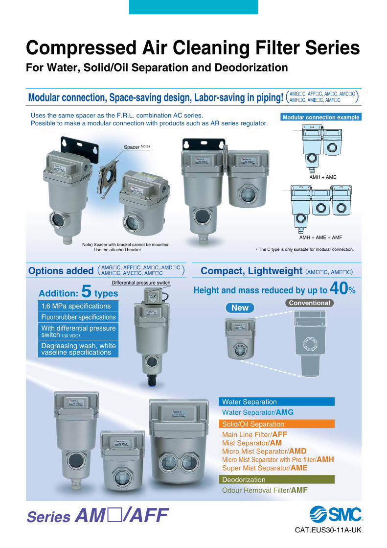
Series AM / AFF Height and mass reduced by up to 40 % Conventional New ∗ The C type is only suitable for modular connection. Spacer Note) Differential pressure switch Uses the same spacer as the F.R.L. combination AC series. Possible to make a modular connection with products such as AR series regulator. AMH + AME AMH + AME + AMF Modular connection example Note) Spacer with bracket cannot be mounted. Use the attached bracket. 1.6 MPa specifications Fluororubber specifications With differential pressure switch (30 VDC) Degreasing wash, white vaseline specifications Addition: 5 types Water Separation Water Separator/AMG Solid/Oil Separation Main Line Filter/AFF Mist Separator/AM Micro Mist Separator/AMD Micro Mist Separator with Pre-filter/AMH Super Mist Separator/AME Deodorization Odour Removal Filter/AMF Compressed Air Cleaning Filter Series For Water, Solid/Oil Separation and Deodorization Modular connection, Space-saving design, Labor-saving in piping! AMGC, AFFC, AMC, AMDC AMHC, AMEC, AMFC Options added AMGC, AFFC, AMC, AMDC AMHC, AMEC, AMFC Compact, Lightweight (AMEC, AMFC) CAT.EUS30-11A-UK
-
Upload
dangkhuong -
Category
Documents
-
view
213 -
download
0
Transcript of Compressed Air Cleaning Filter Series - SMC ETech · Symbol R: IN-OUT reversal direction Air flow...
Series AM�/AFF
Height and mass reduced by up to 40%Conventional
New
∗ The C type is only suitable for modular connection.
Spacer Note)
Differential pressure switch
Uses the same spacer as the F.R.L. combination AC series.Possible to make a modular connection with products such as AR series regulator.
AMH + AME
AMH + AME + AMF
Modular connection example
Note) Spacer with bracket cannot be mounted.Use the attached bracket.
1.6 MPa specifications
Fluororubber specifications
With differential pressure switch (30 VDC)
Degreasing wash, white vaseline specifications
Addition: 5 types
Water Separation
Water Separator/AMG
Solid/Oil Separation
Main Line Filter/AFFMist Separator/AMMicro Mist Separator/AMDMicro Mist Separator with Pre-filter/AMHSuper Mist Separator/AME
Deodorization
Odour Removal Filter/AMF
Compressed Air Cleaning Filter SeriesFor Water, Solid/Oil Separation and Deodorization
Modular connection, Space-saving design, Labor-saving in piping! AMG�C, AFF�C, AM�C, AMD�CAMH�C, AME�C, AMF�C
Options added AMG�C, AFF�C, AM�C, AMD�CAMH�C, AME�C, AMF�C Compact, Lightweight (AME�C, AMF�C)
CAT.EUS30-11A-UK
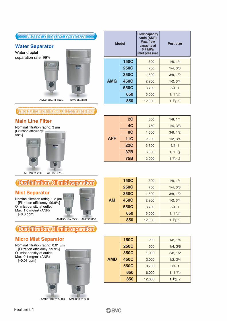
Water SeparatorWater droplet separation rate: 99%
Nominal filtration rating: 3 μm [Filtration efficiency: 99%]
Main Line Filter
Mist Separator
Micro Mist Separator
Nominal filtration rating: 0.3 μm [Filtration efficiency: 99.9%]Oil mist density at outlet:Max. 1.0 mg/m3 (ANR) [≈0.8 ppm]
Nominal filtration rating: 0.01 μm [Filtration efficiency: 99.9%]Oil mist density at outlet:Max. 0.1 mg/m3 (ANR) [≈0.08 ppm]
Water droplet removalWater droplet removal
Large dust particle filtration, Oil droplet separationLarge dust particle filtration, Oil droplet separation
Dust filtration, Oil mist separationDust filtration, Oil mist separationDust filtration, Oil mist separation
Dust filtration, Oil mist separationDust filtration, Oil mist separationDust filtration, Oil mist separation
AMG150C to 550C
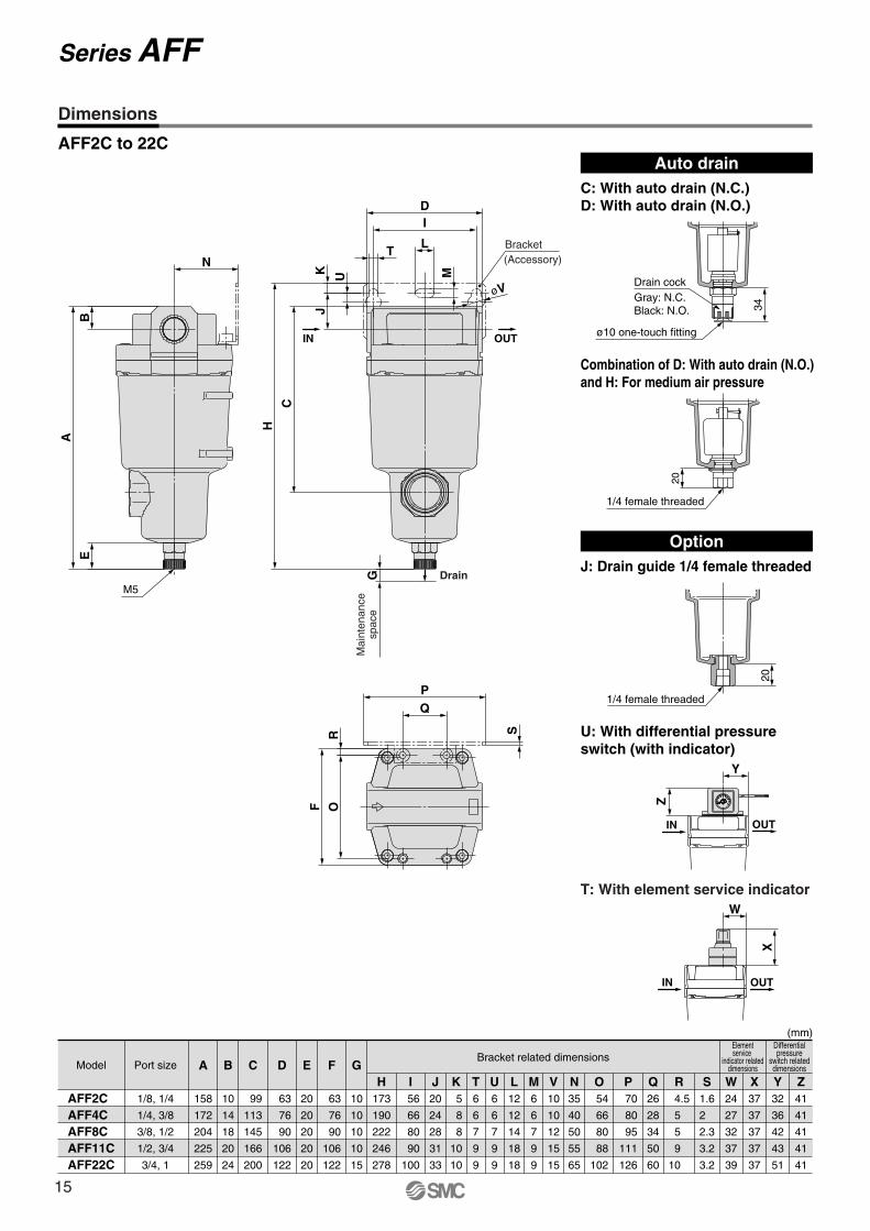
AFF2C to 22C
AM150C to 550C
AMD150C to 550C AMD650 to 850
AM650/850
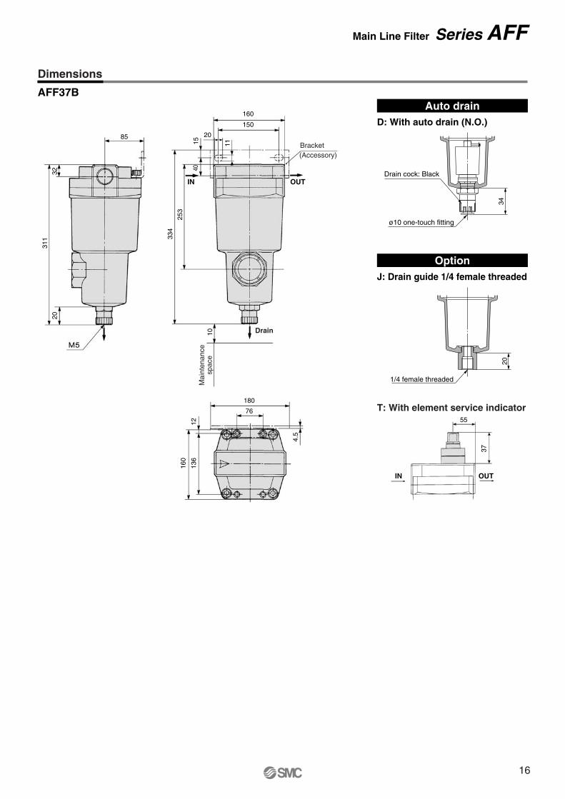
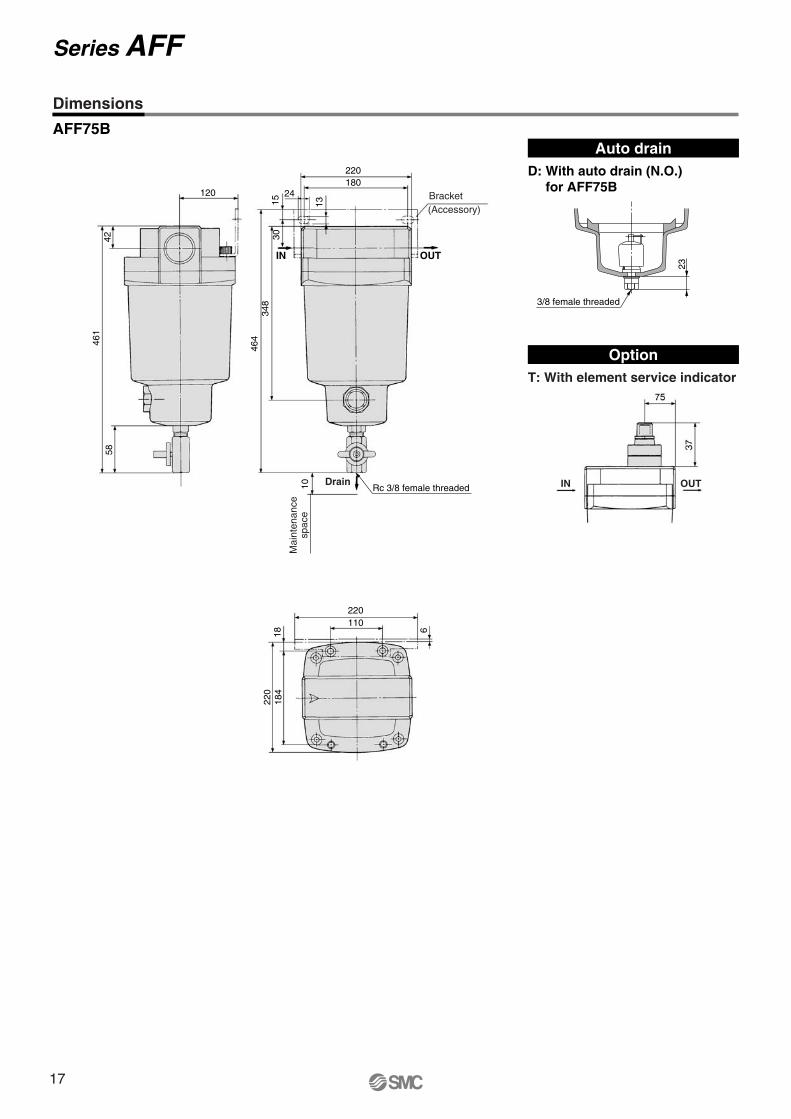
AFF37B/75B
AMG650/850
AM
300
750
1,500
2,200
3,700
6,000
12,000
1/8, 1/4
1/4, 3/8
3/8, 1/2
1/2, 3/4
3/4, 1
1, 1 1/2
1 1/2, 2
150C
250C
350C
450C
550C
650
850
AMD
200
500
1,000
2,000
3,700
6,000
12,000
1/8, 1/4
1/4, 3/8
3/8, 1/2
1/2, 3/4
3/4, 1
1, 1 1/2
1 1/2, 2
150C
250C
350C
450C
550C
650
850
AMG
300
750
1,500
2,200
3,700
6,000
12,000
1/8, 1/4
1/4, 3/8
3/8, 1/2
1/2, 3/4
3/4, 1
1, 1 1/2
1 1/2, 2
150C
250C
350C
450C
550C
650
850
AFF
300
750
1,500
2,200
3,700
6,000
12,000
1/8, 1/4
1/4, 3/8
3/8, 1/2
1/2, 3/4
3/4, 1
1, 1 1/2
1 1/2, 2
2C
4C
8C
11C
22C
37B
75B
Model
Flow capacityl /min (ANR)Max. flow
capacity at0.7 MPa
inlet pressure
Port size
Dust filtration, Oil mist separation
Dust filtration, Oil mist adsorption
Deodorization
Features 1
Water droplet removal
Large dust particle filtration, Oil droplet separation
Dust filtration, Oil mist separation
Dust filtration, Oil mist separation
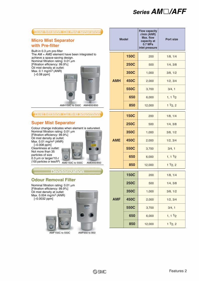
Micro Mist Separatorwith Pre-filter
Super Mist Separator
Odour Removal Filter
Built-in 0.3 μm pre-filterThe AM + AMD element have been integrated toachieve a space-saving design.Nominal filtration rating: 0.01 μm [Filtration efficiency: 99.9%]Oil mist density at outlet:Max. 0.1 mg/m3 (ANR) [≈0.08 ppm]
Colour change indicates when element is saturated.Nominal filtration rating: 0.01 μm [Filtration efficiency: 99.9%]Oil mist density at outlet:Max. 0.01 mg/m3 (ANR) [≈0.008 ppm]Cleanliness at outlet: Not more than 35 particles of size 0.3 μm or larger/10 l (100 particles or less/ft3)
Nominal filtration rating: 0.01 μm [Filtration efficiency: 99.9%]Oil mist density at outlet:Max. 0.004 mg/m3 (ANR) [≈0.0032 ppm]
Dust filtration, Oil mist separationDust filtration, Oil mist separation
Dust filtration, Oil mist adsorptionDust filtration, Oil mist adsorption
DeodorizationDeodorization
AMH150C to 550C AMH650/850
AME150C to 550C AME650/850
AMF150C to 550C AMF650 to 850
Model
Flow capacityl /min (ANR)Max. flow
capacity at0.7 MPa
inlet pressure
Port size
AMH
200
500
1,000
2,000
3,700
6,000
12,000
1/8, 1/4
1/4, 3/8
3/8, 1/2
1/2, 3/4
3/4, 1
1, 1 1/2
1 1/2, 2
150C
250C
350C
450C
550C
650
850
AME
200
500
1,000
2,000
3,700
6,000
12,000
1/8, 1/4
1/4, 3/8
3/8, 1/2
1/2, 3/4
3/4, 1
1, 1 1/2
1 1/2, 2
150C
250C
350C
450C
550C
650
850
AMF
200
500
1,000
2,000
3,700
6,000
12,000
1/8, 1/4
1/4, 3/8
3/8, 1/2
1/2, 3/4
3/4, 1
1, 1 1/2
1 1/2, 2
150C
250C
350C
450C
550C
650
850
Series AM�/AFF
Features 2
Series AM�/AFFCompressed Air Cleaning Filter Series
SeriesAMG
Series
—
Nominalfiltration rating
—
Smell
—
Oil mist densityat outlet
99%
Waterremoval
rate Page
P.2
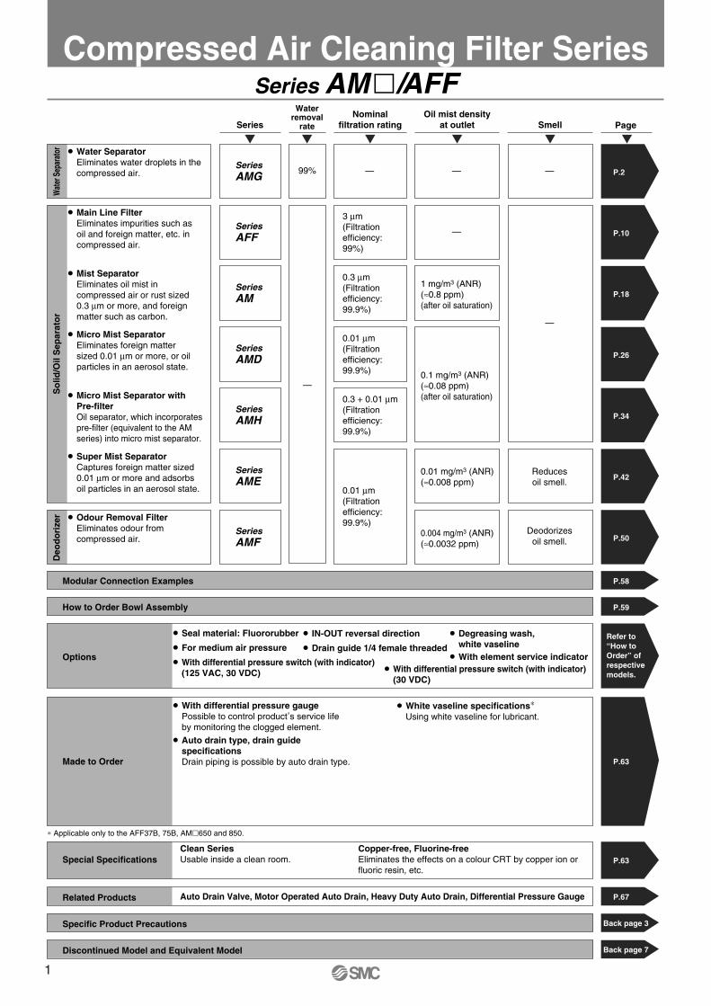
� Water Separator Eliminates water droplets in thecompressed air.
SeriesAFF
3 μm(Filtration efficiency:99%)
—
—
—
P.10
� Main Line FilterEliminates impurities such as oil and foreign matter, etc. in compressed air.
SeriesAM
0.3 μm(Filtration efficiency:99.9%)
1 mg/m3 (ANR)(≈0.8 ppm)(after oil saturation)
P.18
� Mist SeparatorEliminates oil mist in compressed air or rust sized 0.3 μm or more, and foreign matter such as carbon.
SeriesAMD
0.01 μm(Filtration efficiency:99.9%) 0.1 mg/m3 (ANR)
(≈0.08 ppm)(after oil saturation)
P.26
� Micro Mist Separator Eliminates foreign mattersized 0.01 μm or more, or oil particles in an aerosol state.
SeriesAMH
0.3 + 0.01 μm(Filtration efficiency:99.9%)
P.34
� Micro Mist Separator withPre-filterOil separator, which incorporates pre-filter (equivalent to the AM series) into micro mist separator.
SeriesAME
0.01 μm(Filtration efficiency:99.9%)
Reducesoil smell.
0.01 mg/m3 (ANR)(≈0.008 ppm)
P.42
� Super Mist SeparatorCaptures foreign matter sized 0.01 μm or more and adsorbsoil particles in an aerosol state.
SeriesAMF
Deodorizesoil smell.
0.004 mg/m3 (ANR)(≈0.0032 ppm)
P.50
� Odour Removal FilterEliminates odour from compressed air.
∗ Applicable only to the AFF37B, 75B, AM�650 and 850.
P.63Special SpecificationsClean Series Usable inside a clean room.
Copper-free, Fluorine-freeEliminates the effects on a colour CRT by copper ion or fluoric resin, etc.
P.58Modular Connection Examples
P.59How to Order Bowl Assembly
Back page 3Specific Product Precautions
Back page 7Discontinued Model and Equivalent Model
P.67Related Products Auto Drain Valve, Motor Operated Auto Drain, Heavy Duty Auto Drain, Differential Pressure Gauge
P.63Made to Order
� With differential pressure gauge Possible to control product
,s service life
by monitoring the clogged element. � Auto drain type, drain guide
specificationsDrain piping is possible by auto drain type.
� White vaseline specifications∗Using white vaseline for lubricant.
Options
� Seal material: Fluororubber � IN-OUT reversal direction � Degreasing wash, white vaseline � For medium air pressure � Drain guide 1/4 female threaded
� With element service indicator� With differential pressure switch (with indicator)
(125 VAC, 30 VDC) � With differential pressure switch (with indicator)(30 VDC)
Wat
er S
epar
ator
D
eod
ori
zer
So
lid/O
il S
epar
ato
r
Refer to “How to Order” of respective models.
1
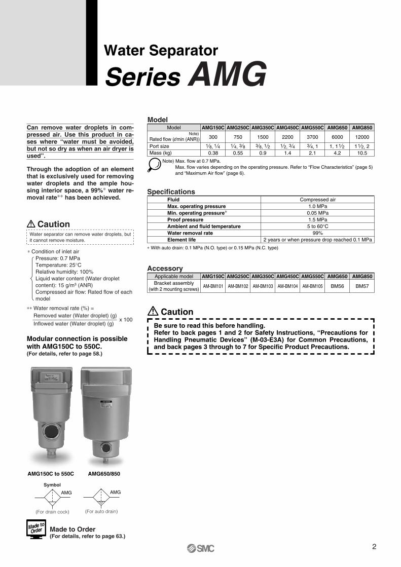
Water Separator
Series AMG
Made to Order (For details, refer to page 63.)
Can remove water droplets in com-pressed air. Use this product in ca-ses where “water must be avoided, but not so dry as when an air dryer is used”.
Through the adoption of an element that is exclusively used for removing water droplets and the ample hou-sing interior space, a 99%∗ water re-moval rate∗∗ has been achieved.
CautionWater separator can remove water droplets, but it cannot remove moisture.
∗ Condition of inlet airPressure: 0.7 MPaTemperature: 25°CRelative humidity: 100%Liquid water content (Water droplet content): 15 g/m3 (ANR) Compressed air flow: Rated flow of each model
∗∗ Water removal rate (%) =Removed water (Water droplet) (g)
Inflowed water (Water droplet) (g)
CautionBe sure to read this before handling.Refer to back pages 1 and 2 for Safety Instructions, “Precautions for Handling Pneumatic Devices” (M-03-E3A) for Common Precautions, and back pages 3 through to 7 for Specific Product Precautions.
Rated flow (l/min (ANR))Note)
Port sizeMass (kg)
Model
300
AMG150C
750
AMG250C
1500
AMG350C
2200
AMG450C
3700
AMG550C
6000
AMG650
12000
0.38 0.55 0.9 1.4 2.1 4.2 10.5
AMG850
Note) Max. flow at 0.7 MPa. Max. flow varies depending on the operating pressure. Refer to “Flow Characteristics” (page 5) and “Maximum Air flow” (page 6).
1 8, 1 4 1 4, 3 8 3 8, 1 2 1 2, 3 4 13 4, 11, 1 2 1 21 2,
Model
0.05 MPa1.5 MPa
FluidMax. operating pressureMin. operating pressure∗Proof pressureAmbient and fluid temperatureWater removal rateElement life
Compressed air1.0 MPa
5 to 60°C99%
2 years or when pressure drop reached 0.1 MPa
∗ With auto drain: 0.1 MPa (N.O. type) or 0.15 MPa (N.C. type)
Specifications
Symbol
AMG150C AMG250C AMG350C AMG450C AMG550C AMG650 AMG850
AM-BM101 AM-BM102 AM-BM103 AM-BM104 AM-BM105 BM56 BM57
Applicable modelAccessory
Bracket assembly(with 2 mounting screws)
AMG150C to 550C AMG650/850
Modular connection is possible with AMG150C to 550C.(For details, refer to page 58.)
x 100
AMG
(For drain cock)
AMG
(For auto drain)
2
How to Order
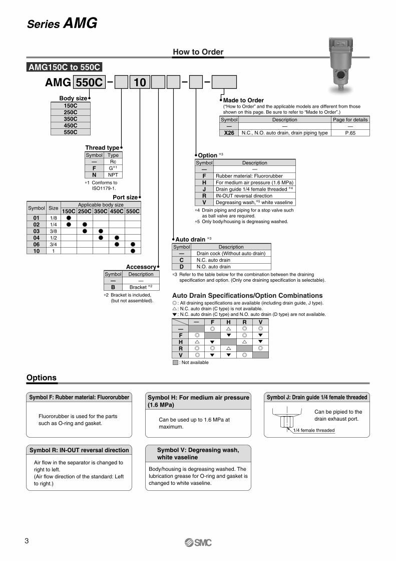
AMG 550C 10Body size
150C250C350C450C550C
Options
Symbol F: Rubber material: Fluororubber
Fluororubber is used for the parts such as O-ring and gasket.
Symbol H: For medium air pressure(1.6 MPa)
Can be used up to 1.6 MPa at maximum.
Symbol J: Drain guide 1/4 female threaded
1/4 female threaded
Can be pipied to the drain exhaust port.
Symbol R: IN-OUT reversal direction
Air flow in the separator is changed to right to left. (Air flow direction of the standard: Left to right.)
Symbol V: Degreasing wash,white vaseline
Body/housing is degreasing washed. The lubrication grease for O-ring and gasket is changed to white vaseline.
∗3 Refer to the table below for the combination between the draining specification and option. (Only one draining specification is selectable).
Auto drain ∗3
CD
Drain cock (Without auto drain)N.C. auto drainN.O. auto drain
Symbol—
Description
AMG150C to 550C
Thread type
FN
RcG∗1
NPT
Symbol—
Type
∗1 Conforms to ISO1179-1.
Port size
010203040610
Symbol
1/81/43/81/23/41
Size150C
Applicable body size250C 350C 450C 550C
X26—
N.C., N.O. auto drain, drain piping type
Symbol—
Description Page for details—
P.65
Made to Order(“How to Order” and the applicable models are different from those shown on this page. Be sure to refer to “Made to Order”.)
Option ∗3
FHJRV
Rubber material: FluororubberFor medium air pressure (1.6 MPa)Drain guide 1/4 female threaded ∗4
IN-OUT reversal directionDegreasing wash,∗5 white vaseline
Symbol—
Description—
∗4 Drain piping and piping for a stop valve such as ball valve are required.
∗5 Only body/housing is degreasing washed.
—FHRV
F H R V
Auto Drain Specifications/Option Combinations
AccessoryDescription
—Bracket ∗2
Symbol
B—
∗2 Bracket is included, (but not assembled). : All draining specifications are available (including drain guide, J type).
: N.C. auto drain (C type) is not available.: N.C. auto drain (C type) and N.O. auto drain (D type) are not available.
: Not available
—
Series AMG
3
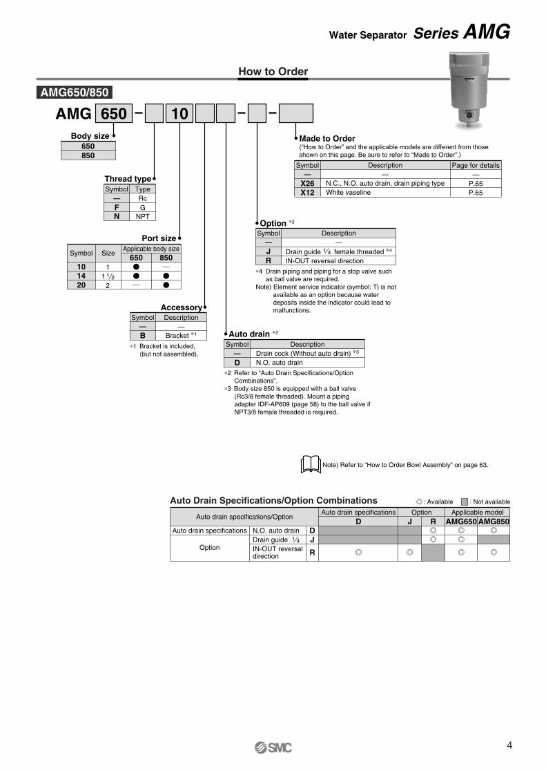
AMG 650 10
101420
Port size
11 1 2
2
650 850Symbol Size
Applicable body size
—
Thread type
FN
RcG
NPT
Symbol Type
Description—
N.C., N.O. auto drain, drain piping typeWhite vaseline
Page for details—
P.65P.65
X26X12
Symbol—
Made to Order(“How to Order” and the applicable models are different from those shown on this page. Be sure to refer to “Made to Order”.)
Auto drain ∗2
D∗2 Refer to “Auto Drain Specifications/Option
Combinations”.∗3 Body size 850 is equipped with a ball valve
(Rc3/8 female threaded). Mount a piping adapter IDF-AP609 (page 58) to the ball valve if NPT3/8 female threaded is required.
DescriptionDrain cock (Without auto drain) ∗3
N.O. auto drain
Symbol—
Body size650850
Auto drain specifications/Option
Auto drain specifications
Option
Auto drain specifications Option
DJ
R
D J RApplicable model
AMG650 AMG850N.O. auto drainDrain guide 1 4
IN-OUT reversal direction
Auto Drain Specifications/Option Combinations
How to Order
Note) Refer to “How to Order Bowl Assembly” on page 63.
AMG650/850
AccessoryDescription
—Bracket ∗1
Symbol
B—
∗1 Bracket is included, (but not assembled).
Option ∗2
J Drain guide female threaded ∗4
IN-OUT reversal directionR
Description—
Symbol—
∗4 Drain piping and piping for a stop valve such as ball valve are required.
Note) Element service indicator (symbol: T) is not available as an option because water deposits inside the indicator could lead to malfunctions.
: Available : Not available
1 4
Water Separator Series AMG
4
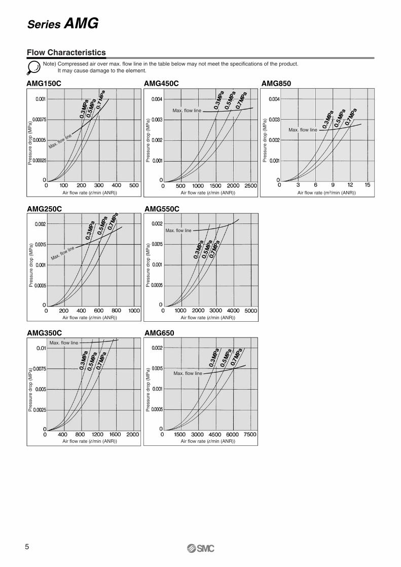
AMG250C AMG550C
AMG350C AMG650
Note) Compressed air over max. flow line in the table below may not meet the specifications of the product.It may cause damage to the element.
AMG150C AMG450C AMG850
Flow Characteristics
Pre
ssur
e dr
op (
MP
a)P
ress
ure
drop
(M
Pa)
Pre
ssur
e dr
op (
MP
a)
Pre
ssur
e dr
op (
MP
a)
Pre
ssur
e dr
op (
MP
a)
Pre
ssur
e dr
op (
MP
a)P
ress
ure
drop
(M
Pa)
Max. flow line
Max. flow line
Max. flow line
Max. flow line
Max. flow line
Max. flow line
Max. flow line
Series AMG
Air flow rate (l /min (ANR)) Air flow rate (l /min (ANR))
Air flow rate (l /min (ANR)) Air flow rate (l /min (ANR))
Air flow rate (l /min (ANR)) Air flow rate (l /min (ANR))
Air flow rate (m3/min (ANR))
5
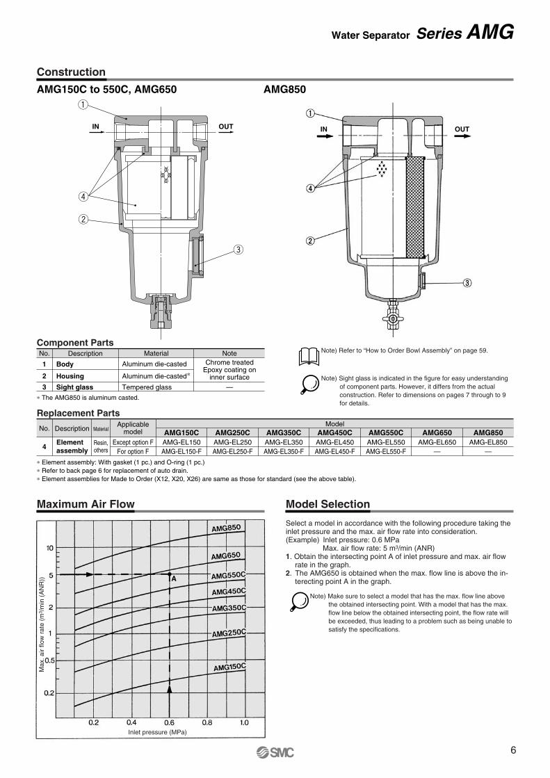
Note) Refer to “How to Order Bowl Assembly” on page 59.
Note) Sight glass is indicated in the figure for easy understanding of component parts. However, it differs from the actual construction. Refer to dimensions on pages 7 through to 9 for details.
Construction
Maximum Air Flow Model Selection
AMG150C to 550C, AMG650
No.
4
DescriptionApplicable
model
Except option FFor option F
Material
Resin,others
Elementassembly
AMG150CAMG-EL150AMG-EL150-F
AMG250CAMG-EL250AMG-EL250-F
AMG350CAMG-EL350AMG-EL350-F
AMG450CModel
AMG-EL450AMG-EL450-F
AMG550CAMG-EL550AMG-EL550-F
AMG650AMG-EL650
—
AMG850AMG-EL850
—
∗ Element assembly: With gasket (1 pc.) and O-ring (1 pc.)∗ Refer to back page 6 for replacement of auto drain.∗ Element assemblies for Made to Order (X12, X20, X26) are same as those for standard (see the above table).
Replacement Parts
AMG850
Select a model in accordance with the following procedure taking the inlet pressure and the max. air flow rate into consideration.(Example) Inlet pressure: 0.6 MPa
Max. air flow rate: 5 m3/min (ANR)1. Obtain the intersecting point A of inlet pressure and max. air flow
rate in the graph.2. The AMG650 is obtained when the max. flow line is above the in-
terecting point A in the graph.
OUTIN OUTIN
q
r
w
e
No.
2
3
1
Description Material Note
Aluminum die-casted∗Aluminum die-casted
Tempered glass
Chrome treatedEpoxy coating on
inner surface—
Housing
Body
Sight glass
Component Parts
∗ The AMG850 is aluminum casted.
Note) Make sure to select a model that has the max. flow line above the obtained intersecting point. With a model that has the max. flow line below the obtained intersecting point, the flow rate will be exceeded, thus leading to a problem such as being unable to satisfy the specifications.
Max
. air
flow
rat
e (m
3 /m
in (
AN
R))
Inlet pressure (MPa)
Water Separator Series AMG
6
M
øV
Drain
IN OUT
(Accessory)Bracket
G
U
DI
LT
KJ
C
H
Mai
nten
ance
spac
e
R S
PQ
OF
M5
A
EB
N
ø10 one-touch fitting
34
Drain cockGray: N.C.Black: N.O.
20
1/4 female threaded
20
1/4 female threaded
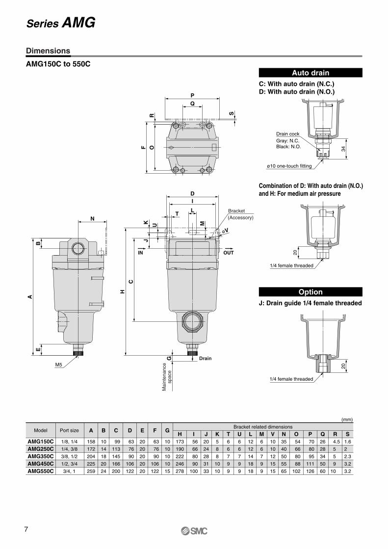
Dimensions
AMG150C to 550C
(mm)
AMG150CAMG250CAMG350CAMG450CAMG550C
AModel Port sizeBracket related dimensions
158
172
204
225
259
1/8, 1/4
1/4, 3/8
3/8, 1/2
1/2, 3/4
3/4, 1
B
10
14
18
20
24
C
99
113
145
166
200
D
63
76
90
106
122
E
20
20
20
20
20
F
63
76
90
106
122
G
10
10
10
10
15
H173
190
222
246
278
I 56
66
80
90
100
J20
24
28
31
33
K5
8
8
10
10
T6
6
7
9
9
U6
6
7
9
9
L12
12
14
18
18
M6
6
7
9
9
V10
10
12
15
15
N35
40
50
55
65
O 54
66
80
88
102
P 70
80
95
111
126
Q26
28
34
50
60
R 4.5
5
5
9
10
S1.6
2
2.3
3.2
3.2
Auto drainC: With auto drain (N.C.)D: With auto drain (N.O.)
OptionJ: Drain guide 1/4 female threaded
Combination of D: With auto drain (N.O.) and H: For medium air pressure
Series AMG
7
85
32
311
20
M5
180
76
4.5
1213
6
160
160
150
20
111540
253
334
10M
aint
enan
cesp
ace
Drain
(Accessory)Bracket
IN OUT
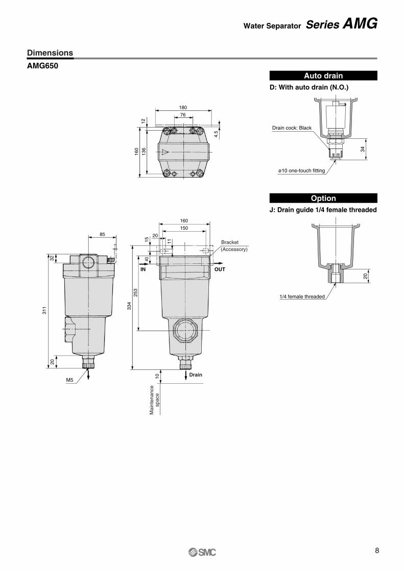
Auto drainD: With auto drain (N.O.)
OptionJ: Drain guide 1/4 female threaded
AMG650
20
1/4 female threaded
34
Drain cock: Black
ø10 one-touch fitting
Dimensions
Water Separator Series AMG
8
120
4246
1
58
220
110
6
1818
4
220
220
180
131530
348
464
10 Rc 3/8 female threaded
24
Mai
nten
ance
spac
e
Drain
IN OUT
(Accessory)Bracket
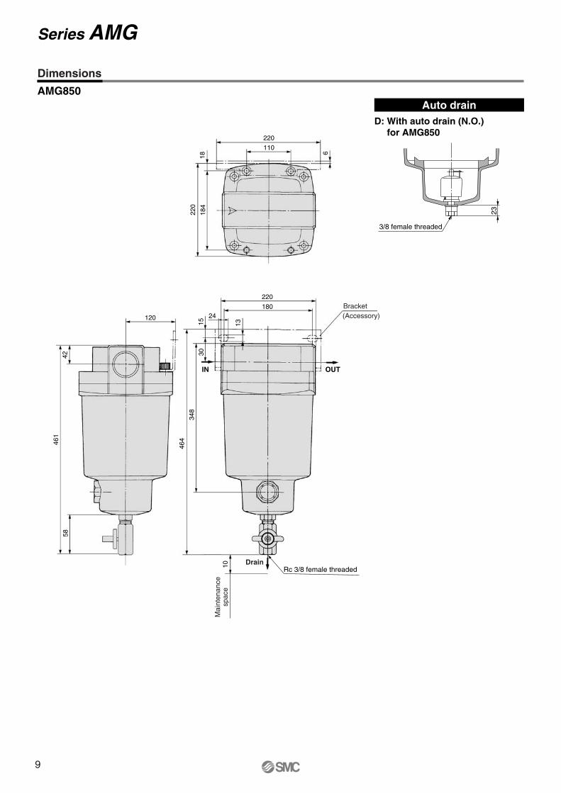
Auto drainD: With auto drain (N.O.)
for AMG850
AMG850
23
3/8 female threaded
Dimensions
Series AMG
9
Symbol
AFF
(For drain cock)
AFF
(For auto drain)
Model Selection Maximum Air FlowMax. flow line
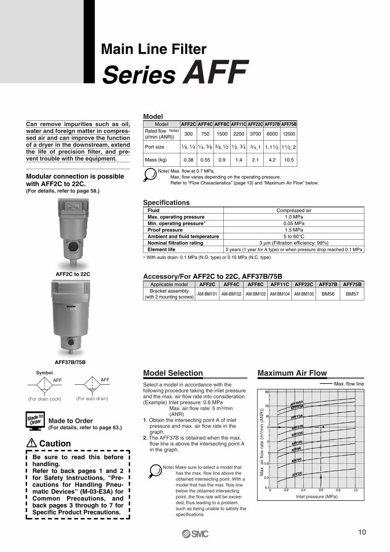
Can remove impurities such as oil, water and foreign matter in compres-sed air and can improve the function of a dryer in the downstream, extend the life of precision filter, and pre-vent trouble with the equipment.
Select a model in accordance with the following procedure taking the inlet pressure and the max. air flow rate into consideration.(Example) Inlet pressure: 0.6 MPa
Max. air flow rate: 5 m3/min (ANR)
1. Obtain the intersecting point A of inlet pressure and max. air flow rate in the graph.
2. The AFF37B is obtained when the max. flow line is above the intersecting point A in the graph.
AFF2C AFF4C AFF8C AFF11C AFF22C AFF37B AFF75B
AM-BM101 AM-BM102 AM-BM103 AM-BM104 AM-BM105 BM56 BM57
Applicable model
Accessory/For AFF2C to 22C, AFF37B/75B
Bracket assembly(with 2 mounting screws)
Rated flow (l/min (ANR))
Port size
Mass (kg)
Model
300
AFF2C AFF4C AFF8C AFF11C AFF22C AFF37B AFF75B
0.38
Note) Max. flow at 0.7 MPa. Max. flow varies depending on the operating pressure.Refer to “Flow Characteristics” (page 13) and “Maximum Air Flow” below.
1 8, 1 4
750
0.55
1 4, 3 8
1500
0.9
3 8, 1 2
2200
1.4
11 2, 3 4
3700
2.1
3 4, 211 2,11, 1 2
6000
4.2
12000
10.5
Note)
Model
0.05 MPa1.5 MPa
FluidMax. operating pressureMin. operating pressure∗Proof pressureAmbient and fluid temperatureNominal filtration ratingElement life
Compressed air1.0 MPa
5 to 60°C3 μm (Filtration efficiency: 99%)
2 years (1 year for A type) or when pressure drop reached 0.1 MPa
∗ With auto drain: 0.1 MPa (N.O. type) or 0.15 MPa (N.C. type)
Specifications
Modular connection is possible with AFF2C to 22C.(For details, refer to page 58.)
AFF37B/75B
AFF2C to 22C
Main Line Filter
Series AFF
Made to Order (For details, refer to page 63.)
Note) Make sure to select a model that has the max. flow line above the obtained intersecting point. With a model that has the max. flow line below the obtained intersecting point, the flow rate will be excee-ded, thus leading to a problem such as being unable to satisfy the specifications.
Max
. air
flow
rat
e (m
3 /m
in (
AN
R))
Inlet pressure (MPa)
Caution
Be sure to read this before handling.Refer to back pages 1 and 2 for Safety Instructions, “Pre-cautions for Handling Pneu-matic Devices” (M-03-E3A) for Common Precautions, and back pages 3 through to 7 for Specific Product Precautions.
10
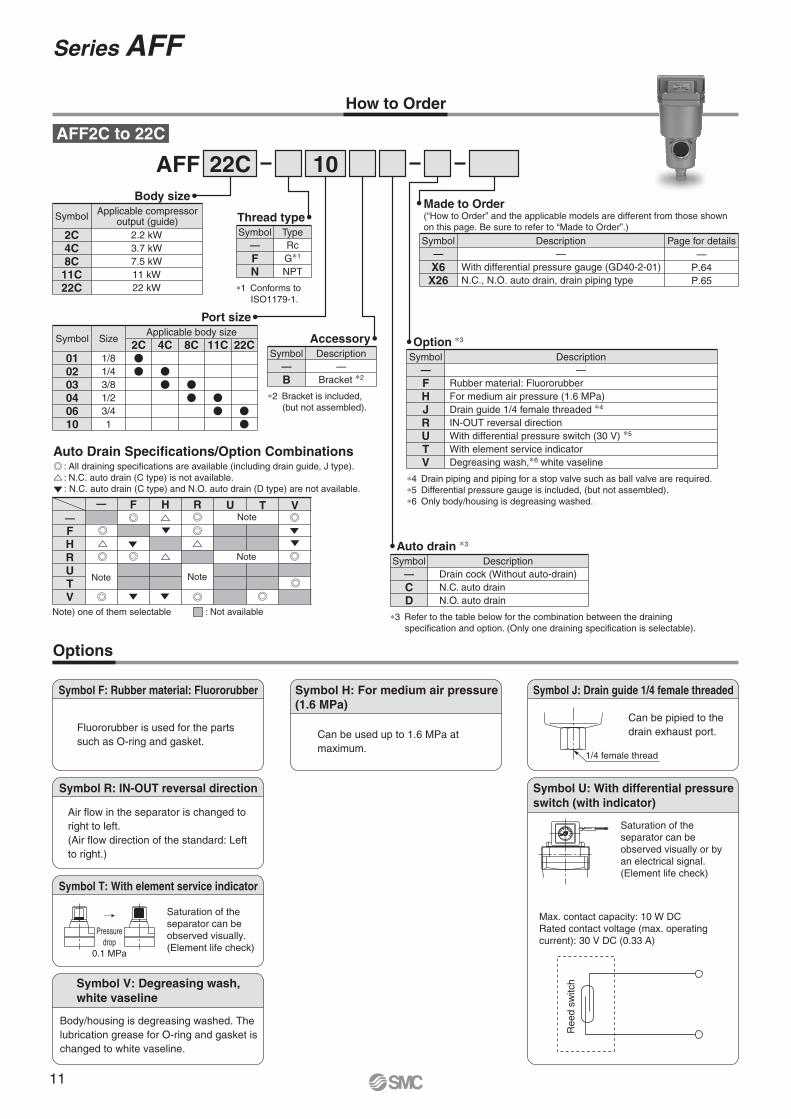
How to Order
AFF 22C 10
Options
Symbol T: With element service indicator
Saturation of the separator can be observed visually. (Element life check)
Pressuredrop
0.1 MPa
SMCMPa
0.2
0.150.1
.05
Symbol F: Rubber material: Fluororubber
Fluororubber is used for the parts such as O-ring and gasket.
Symbol H: For medium air pressure(1.6 MPa)
Can be used up to 1.6 MPa at maximum.
Symbol R: IN-OUT reversal direction
Air flow in the separator is changed to right to left. (Air flow direction of the standard: Left to right.)
∗3 Refer to the table below for the combination between the draining specification and option. (Only one draining specification is selectable).
Auto drain ∗3
CD
Drain cock (Without auto-drain)N.C. auto drainN.O. auto drain
Symbol—
Description
AFF2C to 22C
Body size
2C4C8C11C22C
2.2 kW3.7 kW7.5 kW11 kW22 kW
Symbol Applicable compressoroutput (guide)
Port size
010203040610
1/81/43/81/23/41
Symbol Size2C
Applicable body size4C 8C 11C 22C
Thread type
FN
RcG∗1
NPT
Symbol—
Type
∗1 Conforms to ISO1179-1.
Accessory
B—
Bracket ∗2
Symbol—
Description
∗2 Bracket is included, (but not assembled).
X6X26
—With differential pressure gauge (GD40-2-01)N.C., N.O. auto drain, drain piping type
Symbol—
Description Page for details—
P.64P.65
Option ∗3
FHJRUTV
—Rubber material: FluororubberFor medium air pressure (1.6 MPa)Drain guide 1/4 female threaded ∗4
IN-OUT reversal directionWith differential pressure switch (30 V) ∗5
With element service indicatorDegreasing wash,∗6 white vaseline
Symbol—
Description
∗4 Drain piping and piping for a stop valve such as ball valve are required.∗5 Differential pressure gauge is included, (but not assembled).∗6 Only body/housing is degreasing washed.
Made to Order(“How to Order” and the applicable models are different from those shown on this page. Be sure to refer to “Made to Order”.)
Symbol V: Degreasing wash,white vaseline
Body/housing is degreasing washed. The lubrication grease for O-ring and gasket is changed to white vaseline.
Symbol J: Drain guide 1/4 female threaded
1/4 female thread
Can be pipied to the drain exhaust port.
Symbol U: With differential pressure switch (with indicator)
Saturation of the separator can be observed visually or by an electrical signal. (Element life check)
Max. contact capacity: 10 W DCRated contact voltage (max. operating current): 30 V DC (0.33 A)
Ree
d sw
itch
Auto Drain Specifications/Option Combinations: All draining specifications are available (including drain guide, J type).: N.C. auto drain (C type) is not available.: N.C. auto drain (C type) and N.O. auto drain (D type) are not available.
: Not availableNote) one of them selectable
—FHRUTV
F H R— U T VNote
Note
NoteNote
Series AFF
11
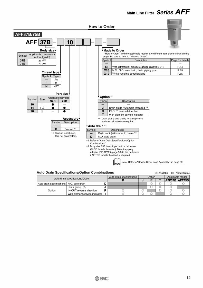
How to Order
AFF 37B 10
37B75B
37 kW75 kW
Body sizeApplicable compressor
output (guide)Symbol
— Rc
Thread type
F GN NPT
TypeSymbol
Description
With differential pressure gauge (GD40-2-01)N.C., N.O. auto drain, drain piping typeWhite vaseline specifications
Page for details—
P.64P.65P.65
X6X26X12
Symbol
Made to Order(“How to Order” and the applicable models are different from those shown on this page. Be sure to refer to “Made to Order”.)
——
Port size
101420
11 1 2
2
SizeApplicable body size
37B 75BSymbol
Auto drain specifications/Option
Auto drain specifications
Option
OptionAuto drain specifications
DJR
D J TRApplicable model
AFF37B AFF75BN.O. auto drainDrain guideIN-OUT reversal direction
TWith element service indicator
1 4
Auto Drain Specifications/Option Combinations
AFF37B/75B
J Drain guide female threaded ∗4
R IN-OUT reversal directionT With element service indicator
Option ∗2
1 4
Description—
Symbol—
∗4 Drain piping and piping for a stop valve such as ball valve are required.
Auto drain ∗2
D∗2 Refer to “Auto Drain Specifications/Option
Combinations”.∗3 Body size 75B is equipped with a ball valve
(Rc3/8 female threaded). Mount a piping adapter IDF-AP609 (page 58) to the ball valve if NPT3/8 female threaded is required.
DescriptionDrain cock (Without auto drain) ∗3
N.O. auto drain
Symbol—
AccessoryDescription
—Bracket ∗1
Symbol
B—
∗1 Bracket is included, (but not assembled).
: Available : Not available
Note) Refer to “How to Order Bowl Assembly” on page 59.
Main Line Filter Series AFF
12
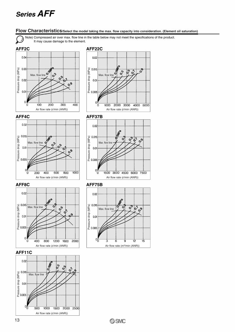
AFF2C AFF22C
AFF4C AFF37B
AFF8C AFF75B
AFF11C
Note) Compressed air over max. flow line in the table below may not meet the specifications of the product.It may cause damage to the element.
Flow Characteristics/Select the model taking the max. flow capacity into consideration. (Element oil saturation)
Pre
ssur
e dr
op (
MP
a)
Air flow rate (l /min (ANR))
Pre
ssur
e dr
op (
MP
a)
Air flow rate (l /min (ANR))
Pre
ssur
e dr
op (
MP
a)
Air flow rate (l /min (ANR))
Pre
ssur
e dr
op (
MP
a)
Air flow rate (l /min (ANR))
Pre
ssur
e dr
op (
MP
a)
Air flow rate (l /min (ANR))
Pre
ssur
e dr
op (
MP
a)
Air flow rate (m3/min (ANR))
Pre
ssur
e dr
op (
MP
a)
Air flow rate (l /min (ANR))
Max. flow line
Max. flow line
Max. flow lineMax. flow line
Max. flow line
Max. flow line
Max. flow line
Series AFF
13
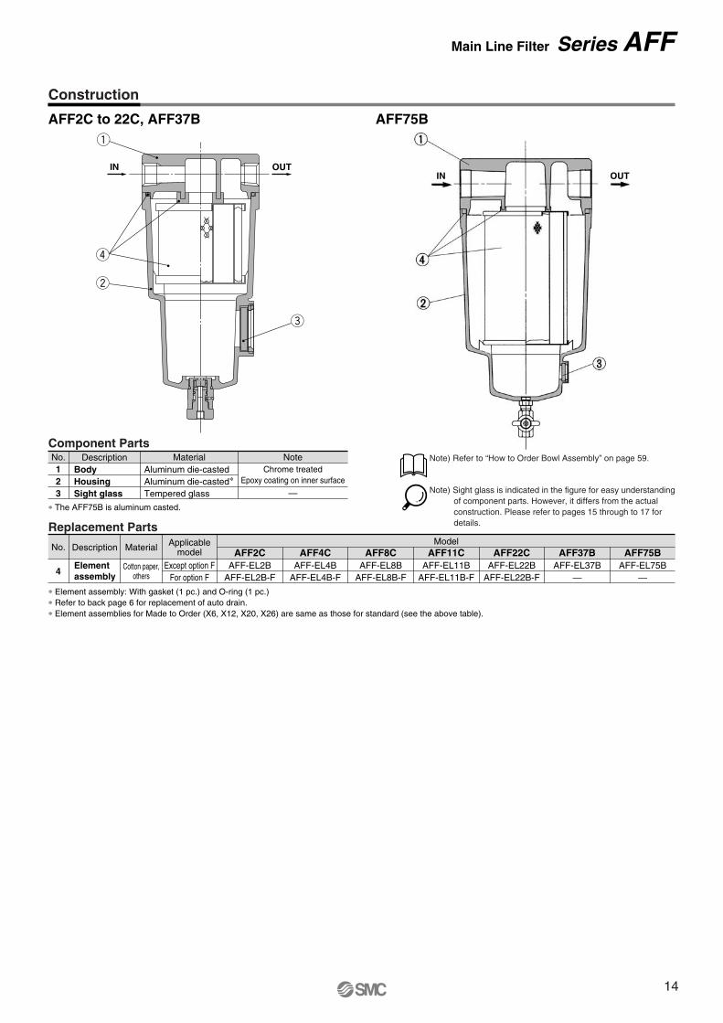
Construction
AFF2C to 22C, AFF37B AFF75B
Note) Refer to “How to Order Bowl Assembly” on page 59.
Note) Sight glass is indicated in the figure for easy understanding of component parts. However, it differs from the actual construction. Please refer to pages 15 through to 17 for details.
OUTIN
q
r
w
e
∗ Element assembly: With gasket (1 pc.) and O-ring (1 pc.)∗ Refer to back page 6 for replacement of auto drain.∗ Element assemblies for Made to Order (X6, X12, X20, X26) are same as those for standard (see the above table).
Replacement Parts
No.
4
Description Material
Cotton paper,others
Elementassembly
AFF2CAFF-EL2B
AFF-EL2B-F
AFF4CAFF-EL4B
AFF-EL4B-F
AFF8CAFF-EL8B
AFF-EL8B-F
AFF11CModel
AFF-EL11BAFF-EL11B-F
AFF22CAFF-EL22B
AFF-EL22B-F
AFF37BAFF-EL37B
—
AFF75BAFF-EL75B
—
Applicablemodel
Except option FFor option F
Component PartsNo.
23
1Description Material Note
Aluminum die-casted∗Aluminum die-casted
Tempered glass
Chrome treatedEpoxy coating on inner surface
—HousingBody
Sight glass∗ The AFF75B is aluminum casted.
OUTIN
Main Line Filter Series AFF
14
ø10 one-touch fitting
34
Drain cockGray: N.C.Black: N.O.
20
1/4 female threaded
Z
Y
IN OUT
W
X
IN OUT
M
øV
Drain
IN OUT
(Accessory)Bracket
G
U
DI
LT
KJ
C
H
Mai
nten
ance
spac
e
R S
PQ
OF
M5
A
EB
N
20
1/4 female threaded
AFF2C to 22C
(mm)
AFF2CAFF4CAFF8CAFF11CAFF22C
AModel Port sizeBracket related dimensions
Elementservice
indicator relateddimensions
Differentialpressure
switch relateddimensions
158
172
204
225
259
1/8, 1/4
1/4, 3/8
3/8, 1/2
1/2, 3/4
3/4, 1
B
10
14
18
20
24
C
99
113
145
166
200
D
63
76
90
106
122
E
20
20
20
20
20
F
63
76
90
106
122
G
10
10
10
10
15
H173
190
222
246
278
I 56
66
80
90
100
J20
24
28
31
33
K 5
8
8
10
10
T6
6
7
9
9
U6
6
7
9
9
L12
12
14
18
18
M6
6
7
9
9
V10
10
12
15
15
N35
40
50
55
65
O 54
66
80
88
102
P 70
80
95
111
126
Q26
28
34
50
60
R 4.5
5
5
9
10
S1.6
2
2.3
3.2
3.2
W24
27
32
37
39
X37
37
37
37
37
Y32
36
42
43
51
Z41
41
41
41
41
Auto drainC: With auto drain (N.C.)D: With auto drain (N.O.)
OptionJ: Drain guide 1/4 female threaded
Combination of D: With auto drain (N.O.) and H: For medium air pressure
U: With differential pressure switch (with indicator)
T: With element service indicator
Dimensions
Series AFF
15
55
37
85
311
2032
180
76
160
136
12
4.5
160
150
20
111540
253
334
10M
aint
enan
cesp
ace
Drain
(Accessory)Bracket
OUTIN
OUTIN
AFF37BAuto drain
D: With auto drain (N.O.)
T: With element service indicator
OptionJ: Drain guide 1/4 female threaded
20
1/4 female threaded
34
Drain cock: Black
ø10 one-touch fitting
Dimensions
Main Line Filter Series AFF
16
120
461
4258
IN OUT
220110
61822
018
4
220180
24
131530
348
464
10 Rc 3/8 female threaded
Mai
nten
ance
spac
e
Drain
(Accessory)Bracket
OUTIN
AFF75BAuto drain
D: With auto drain (N.O.)for AFF75B
OptionT: With element service indicator
23
3/8 female threaded
Dimensions
Series AFF
17
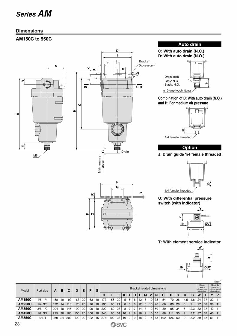
AM150C to 550C AM650/850
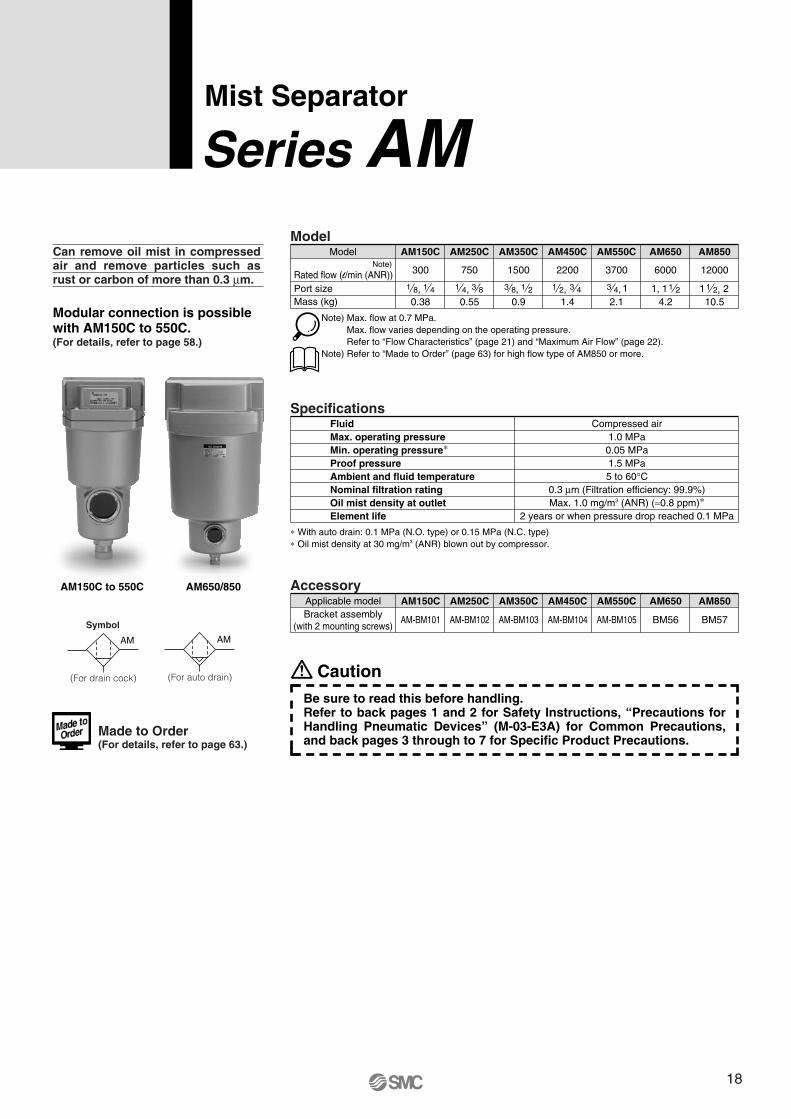
Mist Separator
Series AMCan remove oil mist in compressed air and remove particles such as rust or carbon of more than 0.3 μm.
Model
Rated flow (l/min (ANR))Port sizeMass (kg)
Model
300
AM150C
750
AM250C
1500
AM350C
2200
AM450C
3700
AM550C
6000
AM650
12000
0.38 0.55 0.9 1.4 2.1 4.2 10.5
AM850
Note) Max. flow at 0.7 MPa. Max. flow varies depending on the operating pressure.Refer to “Flow Characteristics” (page 21) and “Maximum Air Flow” (page 22).
Note) Refer to “Made to Order” (page 63) for high flow type of AM850 or more.
1 8, 1 4 1 4, 3 8 3 8, 1 2 1 2, 3 4 3 4, 11,1 1 2 1 21 2,
Specifications
0.05 MPa1.5 MPa
FluidMax. operating pressureMin. operating pressure∗Proof pressureAmbient and fluid temperatureNominal filtration rating
Element life
Compressed air1.0 MPa
5 to 60°C0.3 μm (Filtration efficiency: 99.9%)
Oil mist density at outlet Max. 1.0 mg/m3 (ANR) (≈0.8 ppm)∗2 years or when pressure drop reached 0.1 MPa
∗ With auto drain: 0.1 MPa (N.O. type) or 0.15 MPa (N.C. type)∗ Oil mist density at 30 mg/m3 (ANR) blown out by compressor.
AccessoryAM150C AM250C AM350C AM450C AM550C AM650 AM850
AM-BM101 AM-BM102 AM-BM103 AM-BM104 AM-BM105 BM56 BM57
Applicable modelBracket assembly
(with 2 mounting screws)
Modular connection is possible with AM150C to 550C.(For details, refer to page 58.)
Note)
Made to Order(For details, refer to page 63.)
CautionBe sure to read this before handling.Refer to back pages 1 and 2 for Safety Instructions, “Precautions for Handling Pneumatic Devices” (M-03-E3A) for Common Precautions, and back pages 3 through to 7 for Specific Product Precautions.
Symbol
AM
(For drain cock)
AM
(For auto drain)
18
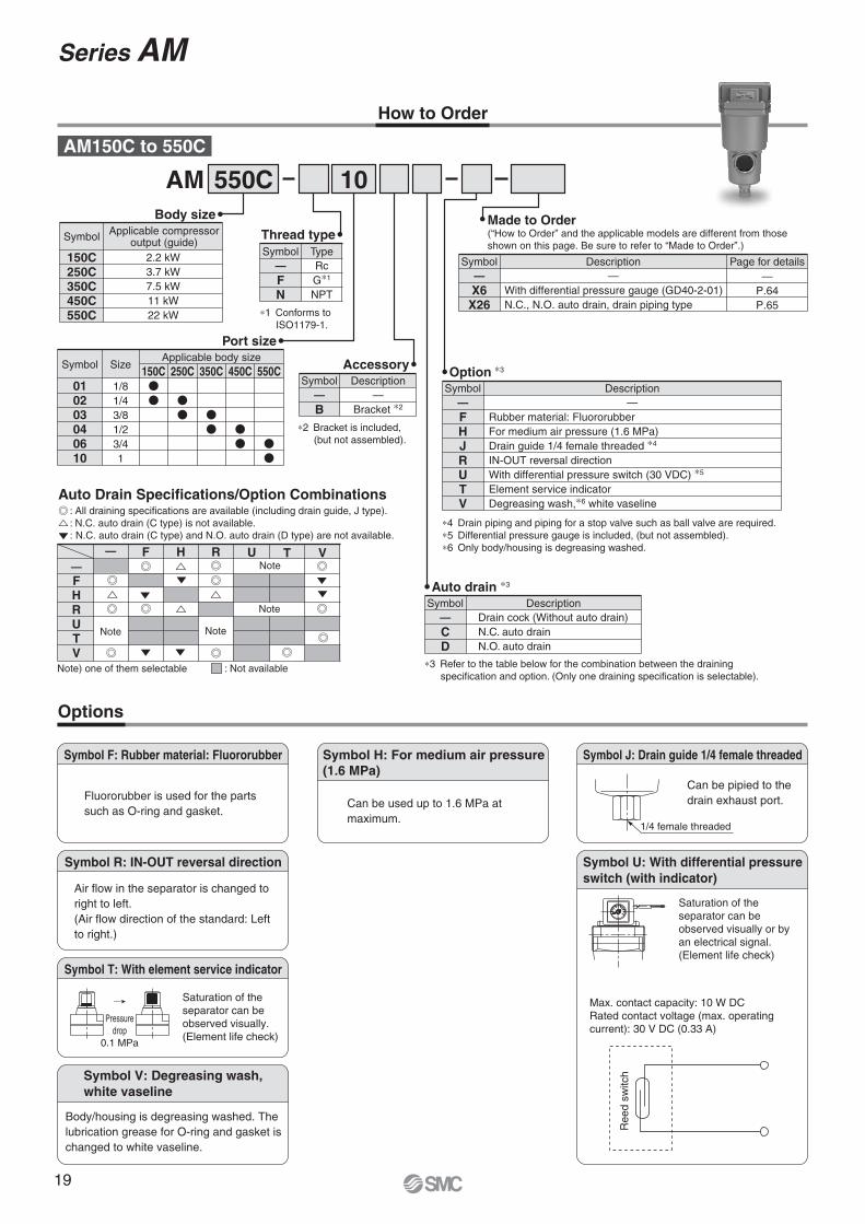
How to Order
Options
Symbol T: With element service indicator
Pressuredrop
0.1 MPa
SMCMPa
0.2
0.150.1
.05
Symbol F: Rubber material: Fluororubber
Fluororubber is used for the parts such as O-ring and gasket.
Symbol J: Drain guide 1/4 female threaded
1/4 female threaded
Symbol R: IN-OUT reversal direction
AM 550C 10
Auto drain ∗3
CD
Drain cock (Without auto drain)N.C. auto drainN.O. auto drain
Symbol—
Description
AM150C to 550C
Body size
150C250C350C450C550C
2.2 kW3.7 kW7.5 kW11 kW22 kW
Symbol Applicable compressoroutput (guide)
Thread type
FN
RcG∗1
NPT
Symbol—
Type
∗1 Conforms to ISO1179-1.
Port size
010203040610
1/81/43/81/23/41
Symbol Size150C
Applicable body size250C 350C 450C 550C Accessory
B—
Bracket ∗2
Symbol—
Description
Made to Order(“How to Order” and the applicable models are different from those shown on this page. Be sure to refer to “Made to Order”.)
Option ∗3
FHJRUTV
—Rubber material: FluororubberFor medium air pressure (1.6 MPa)Drain guide 1/4 female threaded ∗4
IN-OUT reversal directionWith differential pressure switch (30 VDC) ∗5
Element service indicatorDegreasing wash,∗6 white vaseline
Symbol—
Description
∗4 Drain piping and piping for a stop valve such as ball valve are required.∗5 Differential pressure gauge is included, (but not assembled).∗6 Only body/housing is degreasing washed.
Air flow in the separator is changed to right to left. (Air flow direction of the standard: Left to right.)
Symbol V: Degreasing wash,white vaseline
Symbol H: For medium air pressure(1.6 MPa)
Can be used up to 1.6 MPa at maximum.
Symbol U: With differential pressure switch (with indicator)
Saturation of the separator can be observed visually or by an electrical signal. (Element life check)
Max. contact capacity: 10 W DCRated contact voltage (max. operating current): 30 V DC (0.33 A)
Ree
d sw
itch
Can be pipied to the drain exhaust port.
X6X26
—With differential pressure gauge (GD40-2-01)N.C., N.O. auto drain, drain piping type
Symbol—
Description Page for details—
P.64P.65
Saturation of the separator can be observed visually. (Element life check)
Body/housing is degreasing washed. The lubrication grease for O-ring and gasket is changed to white vaseline.
∗3 Refer to the table below for the combination between the draining specification and option. (Only one draining specification is selectable).
∗2 Bracket is included, (but not assembled).
Auto Drain Specifications/Option Combinations: All draining specifications are available (including drain guide, J type).: N.C. auto drain (C type) is not available.: N.C. auto drain (C type) and N.O. auto drain (D type) are not available.
: Not availableNote) one of them selectable
Series AM
—FHRUTV
F H R— U T VNote
Note
NoteNote
19
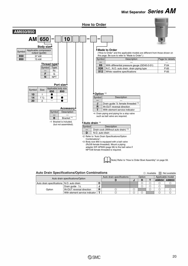
How to Order
1014
Port size
11 1 2
20 2
650 850Symbol Size
Applicable body size
Auto Drain Specifications/Option Combinations
Auto drain specifications/Option
Auto drain specifications
Option
Auto drain specifications Option
DJR
D J TRApplicable modelAM650 AM850
N.O. auto drainDrain guideIN-OUT reversal direction
TWith element service indicator
1 4
AM 650 10
Thread type
— RcF GN NPT
TypeSymbol
Description
With differential pressure gauge (GD40-2-01)N.C., N.O. auto drain, drain piping typeWhite vaseline specifications
Page for details—
P.64P.65P.65
X6X26X12
Symbol
Made to Order(“How to Order” and the applicable models are different from those shown on this page. Be sure to refer to “Made to Order”.)
——
Applicable compressoroutput (guide)
650 37 kW75 kW850
Body size
Symbol
AM650/850
AccessoryDescription
—Bracket ∗1
Symbol
B—
∗1 Bracket is included, (but not assembled). Auto drain ∗2
D∗2 Refer to “Auto Drain Specifications/Option
Combinations”.∗3 Body size 850 is equipped with a ball valve
(Rc3/8 female threaded). Mount a piping adapter IDF-AP609 (page 58) to the ball valve if NPT3/8 female threaded is required.
DescriptionDrain cock (Without auto drain) ∗3
N.O. auto drain
Symbol—
With element service indicator
Option ∗2
IN-OUT reversal direction
1 4Drain guide female threaded ∗4
Description—
JRT
Symbol—
∗4 Drain piping and piping for a stop valve such as ball valve are required.
: Available : Not available
Note) Refer to “How to Order Bowl Assembly” on page 59.
Mist Separator Series AM
20
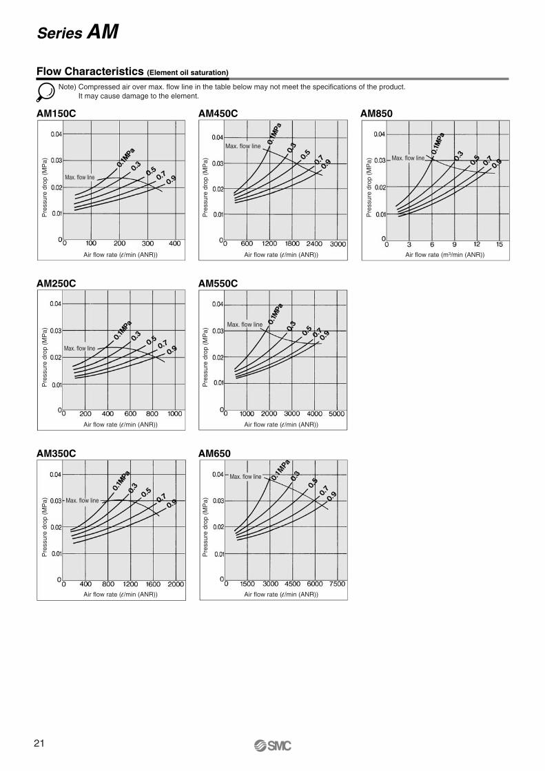
AM150C
AM250C AM550C
AM350C
AM450C AM850
AM650
Note) Compressed air over max. flow line in the table below may not meet the specifications of the product.It may cause damage to the element.
Flow Characteristics (Element oil saturation)
Pre
ssur
e dr
op (
MP
a)
Air flow rate (l /min (ANR))
Pre
ssur
e dr
op (
MP
a)
Air flow rate (l /min (ANR))
Pre
ssur
e dr
op (
MP
a)
Air flow rate (l /min (ANR))
Pre
ssur
e dr
op (
MP
a)
Air flow rate (l /min (ANR))
Pre
ssur
e dr
op (
MP
a)
Air flow rate (l /min (ANR))
Pre
ssur
e dr
op (
MP
a)
Air flow rate (l /min (ANR))
Pre
ssur
e dr
op (
MP
a)
Air flow rate (m3/min (ANR))
Max. flow line
Max. flow line
Max. flow line
Max. flow line
Max. flow line
Max. flow line
Max. flow line
Series AM
21
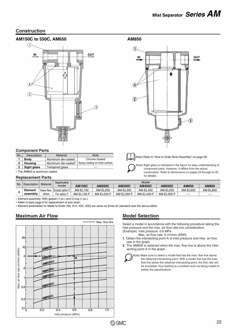
AM150C to 550C, AM650 AM850
Construction
Maximum Air FlowMax. flow line
Model Selection
Max
. air
flow
rat
e (m
3 /m
in (
AN
R))
Inlet pressure (MPa)
Select a model in accordance with the following procedure taking the inlet pressure and the max. air flow rate into consideration.(Example) Inlet pressure: 0.6 MPa
Max. air flow rate: 5 m3/min (ANR)1. Obtain the intersecting point A of inlet pressure and max. air flow
rate in the graph.2. The AM650 is obtained when the max. flow line is above the inter-
secting point A in the graph.
OUTIN
q
r
w
e
Note) Sight glass is indicated in the figure for easy understanding of component parts. However, it differs from the actual construction. Refer to dimensions on pages 23 through to 25 for details.Replacement Parts
∗ Element assembly: With gasket (1 pc.) and O-ring (1 pc.)∗ Refer to back page 6 for replacement of auto drain.∗ Element assemblies for Made to Order (X6, X12, X20, X26) are same as those for standard (see the above table).
No.
4
Description Material
Glass fiber,others
Elementassembly
AM150CAM-EL150
AM-EL150-F
AM250CAM-EL250
AM-EL250-F
AM350CAM-EL350
AM-EL350-F
AM450CModel
AM-EL450AM-EL450-F
AM550CAM-EL550
AM-EL550-F
AM650AM-EL650
—
AM850AM-EL850
—
Applicablemodel
Except option FFor option F
Component PartsNo.
23
1Description Material Note
Aluminum die-casted∗Aluminum die-casted
Tempered glass
Chrome treatedEpoxy coating on inner surface
—HousingBody
Sight glass∗ The AM850 is aluminum casted.
Note) Make sure to select a model that has the max. flow line above the obtained intersecting point. With a model that has the max. flow line below the obtained intersecting point, the flow rate will be exceeded, thus leading to a problem such as being unable to satisfy the specifications.
Note) Refer to “How to Order Bowl Assembly” on page 59.
OUTIN
Mist Separator Series AM
22
ø10 one-touch fitting
34
Drain cockGray: N.C.Black: N.O.
20
1/4 female threaded
Z
Y
IN OUT
W
X
IN OUT
M
øV
Drain
IN OUT
(Accessory)Bracket
G
U
DI
LT
KJ
C
H
Mai
nten
ance
spac
e
R S
PQ
OF
M5
A
EB
N
Dimensions
AM150C to 550C
(mm)
AM150CAM250CAM350CAM450CAM550C
AModel Port sizeBracket related dimensions
Elementservice
indicator relateddimensions
Differentialpressure
switch relateddimensions
158
172
204
225
259
1/8, 1/4
1/4, 3/8
3/8, 1/2
1/2, 3/4
3/4, 1
B
10
14
18
20
24
C
99
113
145
166
200
D
63
76
90
106
122
E
20
20
20
20
20
F
63
76
90
106
122
G
10
10
10
10
15
H173
190
222
246
278
I 56
66
80
90
100
J20
24
28
31
33
K 5
8
8
10
10
T6
6
7
9
9
U6
6
7
9
9
L12
12
14
18
18
M6
6
7
9
9
V10
10
12
15
15
N35
40
50
55
65
O 54
66
80
88
102
P 70
80
95
111
126
Q26
28
34
50
60
R 4.5
5
5
9
10
S1.6
2
2.3
3.2
3.2
W24
27
32
37
39
X37
37
37
37
37
Y32
36
42
43
51
Z41
41
41
41
41
Auto drainC: With auto drain (N.C.)D: With auto drain (N.O.)
OptionJ: Drain guide 1/4 female threaded
Combination of D: With auto drain (N.O.) and H: For medium air pressure
U: With differential pressure switch (with indicator)
T: With element service indicator
20
1/4 female threaded
Series AM
23
55
37
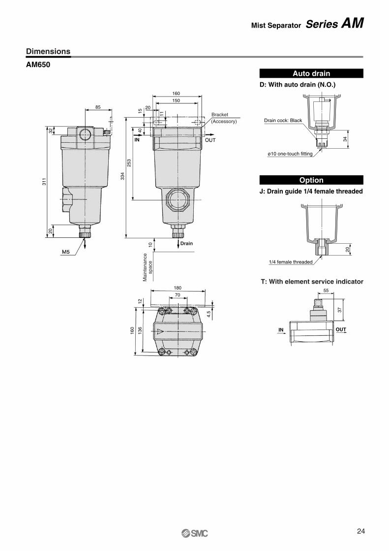
Dimensions
AM650
T: With element service indicator
Auto drainD: With auto drain (N.O.)
OptionJ: Drain guide 1/4 female threaded
20
1/4 female threaded
34
Drain cock: Black
ø10 one-touch fitting
85
3231
120
Mist Separator Series AM
180
70
4.5
1213
6
160
160
150
20
253
1540
11
334
10M
aint
enan
cesp
ace
Drain
(Accessory)Bracket
IN
OUTIN
24

Dimensions
AM850Auto drain
D: With auto drain (N.O.)for AM850
OptionT: With element service indicator
23
3/8 female threaded
Series AM
120
4246
1
58
6
220
110
1818
4
220
220
180
24
15 13
30
348
464
10 Rc 3/8 female threaded
Mai
nten
ance
spac
e
Bracket(Accessory)
Drain
OUTIN
OUTIN
25
Symbol
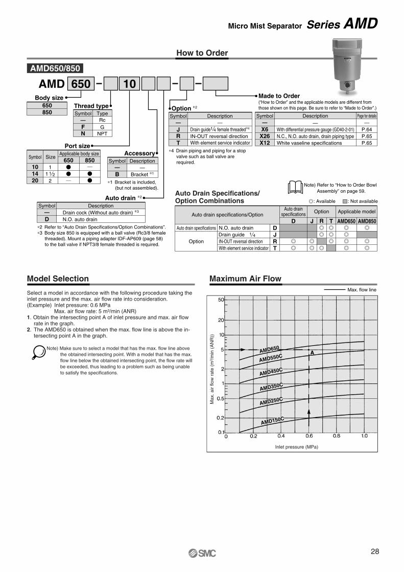
AMD
(For drain cock)
AMD
(For auto drain)
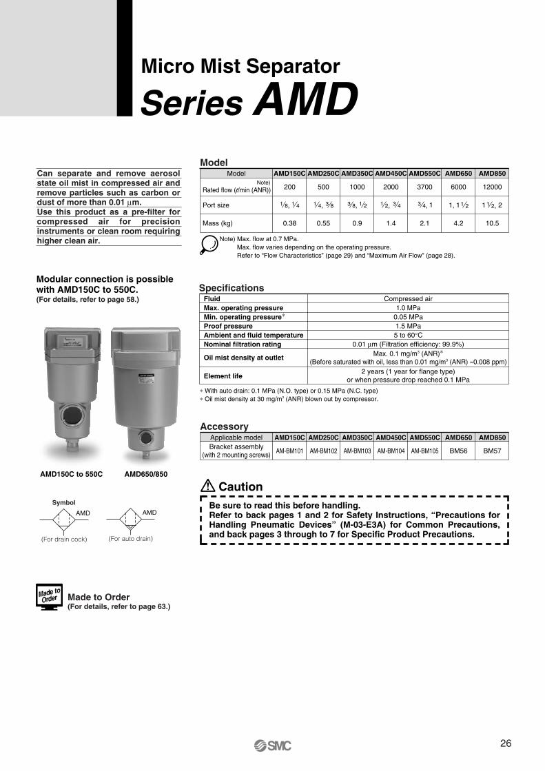
Micro Mist Separator
Series AMDCan separate and remove aerosol state oil mist in compressed air and remove particles such as carbon or dust of more than 0.01 μm. Use this product as a pre-filter for compressed air for precision instruments or clean room requiring higher clean air.
Model
Rated flow (l/min (ANR))
Port size
Mass (kg)
Model
200
AMD150C
500
AMD250C
1000
AMD350C
2000
AMD450C
3700
AMD550C
6000
AMD650
12000
0.38 0.55 0.9 1.4 2.1 4.2 10.5
AMD850
Note) Max. flow at 0.7 MPa. Max. flow varies depending on the operating pressure.Refer to “Flow Characteristics” (page 29) and “Maximum Air Flow” (page 28).
1 8, 1 4 1 4, 3 8 3 8, 1 2 1 2, 3 4 13 4,
Note)
Specifications
0.05 MPa1.5 MPa
FluidMax. operating pressureMin. operating pressure∗Proof pressureAmbient and fluid temperatureNominal filtration rating
Element life
Compressed air1.0 MPa
5 to 60°C0.01 μm (Filtration efficiency: 99.9%)
Oil mist density at outlet Max. 0.1 mg/m3 (ANR)∗(Before saturated with oil, less than 0.01 mg/m3 (ANR) ≈0.008 ppm)
2 years (1 year for flange type)or when pressure drop reached 0.1 MPa
∗ With auto drain: 0.1 MPa (N.O. type) or 0.15 MPa (N.C. type)∗ Oil mist density at 30 mg/m3 (ANR) blown out by compressor.
AccessoryAMD150C AMD250C AMD350C AMD450C AMD550C AMD650 AMD850
AM-BM101 AM-BM102 AM-BM103 AM-BM104 AM-BM105 BM56 BM57
Applicable modelBracket assembly
(with 2 mounting screws)
Modular connection is possible with AMD150C to 550C.(For details, refer to page 58.)
AMD150C to 550C AMD650/850
11, 1 2 1 21 2,
Made to Order (For details, refer to page 63.)
CautionBe sure to read this before handling.Refer to back pages 1 and 2 for Safety Instructions, “Precautions for Handling Pneumatic Devices” (M-03-E3A) for Common Precautions, and back pages 3 through to 7 for Specific Product Precautions.
26
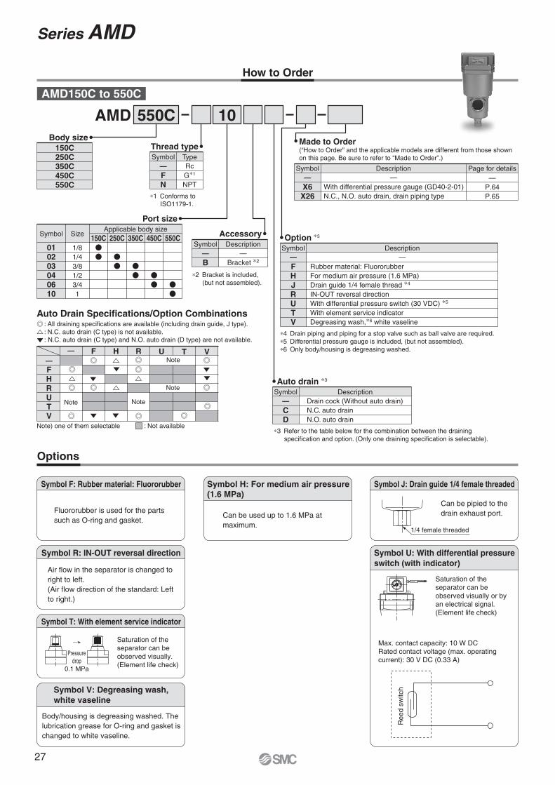
How to Order
Options
SMCMPa
0.2
0.150.1
.05
AMD 550C 10
Auto drain ∗3
CD
Drain cock (Without auto drain)N.C. auto drainN.O. auto drain
Symbol—
Description
Body size150C250C350C450C550C
Thread type
FN
RcG∗1
NPT
Symbol—
Type
∗1 Conforms to ISO1179-1.
Port size
010203040610
1/81/43/81/23/41
Symbol Size150C
Applicable body size250C 350C 450C 550C Accessory
B—
Bracket ∗2
Symbol—
Description
FHJRUTV
Symbol— —
Description
∗4 Drain piping and piping for a stop valve such as ball valve are required.∗5 Differential pressure gauge is included, (but not assembled).∗6 Only body/housing is degreasing washed.
Rubber material: FluororubberFor medium air pressure (1.6 MPa)Drain guide 1/4 female thread ∗4
IN-OUT reversal directionWith differential pressure switch (30 VDC) ∗5
With element service indicatorDegreasing wash,∗6 white vaseline
Made to Order(“How to Order” and the applicable models are different from those shown on this page. Be sure to refer to “Made to Order”.)
AMD150C to 550C
Option ∗3
Symbol F: Rubber material: Fluororubber
Fluororubber is used for the parts such as O-ring and gasket.
Symbol R: IN-OUT reversal direction
Air flow in the separator is changed to right to left. (Air flow direction of the standard: Left to right.)
Symbol T: With element service indicator
Pressuredrop
0.1 MPa
Symbol V: Degreasing wash,white vaseline
Symbol H: For medium air pressure(1.6 MPa)
Can be used up to 1.6 MPa at maximum.
Symbol J: Drain guide 1/4 female threaded
1/4 female threaded
Can be pipied to the drain exhaust port.
Symbol U: With differential pressure switch (with indicator)
Saturation of the separator can be observed visually or by an electrical signal. (Element life check)
Max. contact capacity: 10 W DCRated contact voltage (max. operating current): 30 V DC (0.33 A)
Ree
d sw
itch
X6X26
—With differential pressure gauge (GD40-2-01)N.C., N.O. auto drain, drain piping type
Symbol—
Description Page for details—
P.64P.65
Saturation of the separator can be observed visually. (Element life check)
Body/housing is degreasing washed. The lubrication grease for O-ring and gasket is changed to white vaseline.
∗2 Bracket is included, (but not assembled).
Auto Drain Specifications/Option Combinations: All draining specifications are available (including drain guide, J type).: N.C. auto drain (C type) is not available.: N.C. auto drain (C type) and N.O. auto drain (D type) are not available.
∗3 Refer to the table below for the combination between the draining specification and option. (Only one draining specification is selectable).
Series AMD
: Not availableNote) one of them selectable
—FHRUTV
F H R— U T VNote
Note
NoteNote
27
How to Order
AMD650
AMD550C
AMD450C
AMD350C
AMD250C
AMD150C
Maximum Air FlowModel Selection
AMD 650 10
Free standing type
Max. flow lineSelect a model in accordance with the following procedure taking the inlet pressure and the max. air flow rate into consideration.(Example) Inlet pressure: 0.6 MPa
Max. air flow rate: 5 m3/min (ANR)1. Obtain the intersecting point A of inlet pressure and max. air flow
rate in the graph.2. The AMD650 is obtained when the max. flow line is above the in-
tersecting point A in the graph.
Description
With differential pressure gauge (GD40-2-01)N.C., N.O. auto drain, drain piping typeWhite vaseline specifications
Page for details
—P.64P.65P.65
X6X26X12
Symbol
Made to Order(“How to Order” and the applicable models are different from those shown on this page. Be sure to refer to “Made to Order”.)
——
Thread type
— RcF GN NPT
TypeSymbol
Auto drain specifications/Option
Auto drain specifications
Option
OptionAuto drainspecifications
DJR
D J TR
Applicable model
AMD650 AMD850N.O. auto drainDrain guideIN-OUT reversal direction
TWith element service indicator
1 4
Auto Drain Specifications/Option Combinations : Available : Not available
Port size
101420
11 1 2
2
SizeApplicable body size
650 850Symbol
Body size650850
∗1 Bracket is included, (but not assembled).
AccessoryDescription
—Bracket ∗1
Symbol
B—
Auto drain ∗2
DescriptionDrain cock (Without auto drain) ∗3
N.O. auto drain
Symbol
D—
∗2 Refer to “Auto Drain Specifications/Option Combinations”.∗3 Body size 850 is equipped with a ball valve (Rc3/8 female
threaded). Mount a piping adapter IDF-AP609 (page 58) to the ball valve if NPT3/8 female threaded is required.
With element service indicator
Option ∗2
Drain guide female threaded∗4
IN-OUT reversal direction
1 4
Description—
T
JR
Symbol—
∗4 Drain piping and piping for a stop valve such as ball valve are required.
AMD650/850
Note) Make sure to select a model that has the max. flow line above the obtained intersecting point. With a model that has the max. flow line below the obtained intersecting point, the flow rate will be exceeded, thus leading to a problem such as being unable to satisfy the specifications.
Max
. air
flow
rat
e (m
3 /m
in (
AN
R))
Inlet pressure (MPa)
Note) Refer to “How to Order Bowl Assembly” on page 59.
Micro Mist Separator Series AMD
28
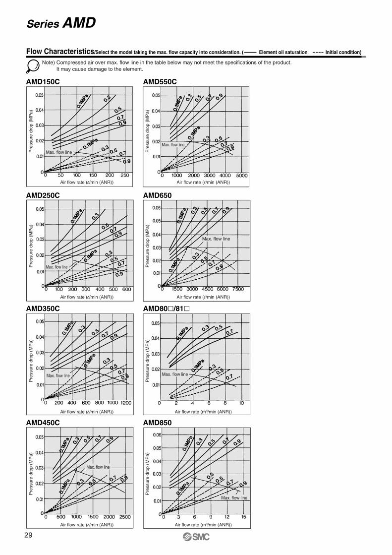
AMD150C
AMD250C
AMD350C
AMD450C AMD850
AMD80�/81�
AMD650 AMD10�0
AMD550C AMD9�0/9�1
Note) Compressed air over max. flow line in the table below may not meet the specifications of the product.It may cause damage to the element.
Flow Characteristics/Select the model taking the max. flow capacity into consideration. ( Element oil saturation Initial condition)
Pre
ssur
e dr
op (
MP
a)
Air flow rate (l /min (ANR))
Pre
ssur
e dr
op (
MP
a)
Air flow rate (l /min (ANR))
Pre
ssur
e dr
op (
MP
a)
Air flow rate (m3/min (ANR))
Pre
ssur
e dr
op (
MP
a)
Air flow rate (l /min (ANR))
Pre
ssur
e dr
op (
MP
a)
Air flow rate (l /min (ANR))
Pre
ssur
e dr
op (
MP
a)
Air flow rate (l /min (ANR))
Pre
ssur
e dr
op (
MP
a)
Air flow rate (m3/min (ANR))
Pre
ssur
e dr
op (
MP
a)
Air flow rate (l /min (ANR))
Pre
ssur
e dr
op (
MP
a)
Air flow rate (m3/min (ANR))
Pre
ssur
e dr
op (
MP
a)
Air flow rate (m3/min (ANR))
Max. flow line
Max. flow line
Max. flow line
Max. flow line
Max. flow line
Max. flow line
Max. flow line
Max. flow line
Max. flow line
Max. flow line
Series AMD
29
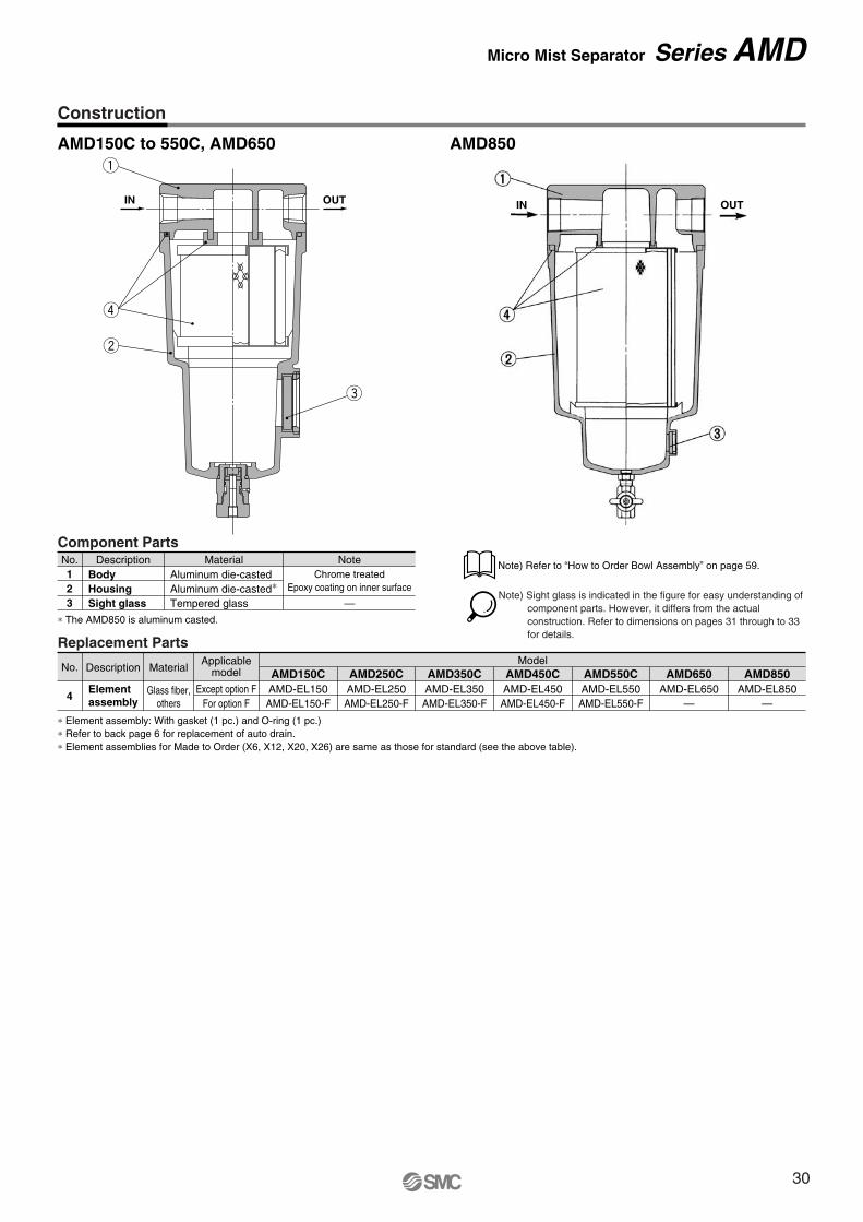
Construction
AMD150C to 550C, AMD650 AMD850
OUTIN OUTIN
q
r
w
e
Replacement Parts
∗ Element assembly: With gasket (1 pc.) and O-ring (1 pc.)∗ Refer to back page 6 for replacement of auto drain.∗ Element assemblies for Made to Order (X6, X12, X20, X26) are same as those for standard (see the above table).
No.
4
Description Material
Glass fiber,others
Elementassembly
AMD150CAMD-EL150AMD-EL150-F
AMD250CAMD-EL250AMD-EL250-F
AMD350CAMD-EL350AMD-EL350-F
AMD450CModel
AMD-EL450AMD-EL450-F
AMD550CAMD-EL550AMD-EL550-F
AMD650AMD-EL650
—
AMD850AMD-EL850
—
Applicablemodel
Except option FFor option F
Component PartsNo.
23
1Description Material Note
Aluminum die-casted∗Aluminum die-casted
Tempered glass
Chrome treatedEpoxy coating on inner surface
—HousingBody
Sight glass∗ The AMD850 is aluminum casted.
Note) Sight glass is indicated in the figure for easy understanding of component parts. However, it differs from the actual construction. Refer to dimensions on pages 31 through to 33 for details.
Note) Refer to “How to Order Bowl Assembly” on page 59.
Micro Mist Separator Series AMD
30
ø10 one-touch fitting
34
Drain cockGray: N.C.Black: N.O.
20
1/4 female threaded
Z
Y
IN OUT
W
X
IN OUT
M
øV
Drain
IN OUT
(Accessory)Bracket
G
U
DI
LT
KJ
C
H
Mai
nten
ance
spac
e
R S
PQ
OF
M5
A
EB
N
20
1/4 female threaded
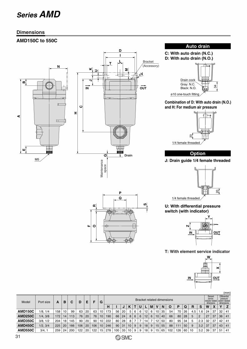
AMD150C to 550C
(mm)
AMD150CAMD250CAMD350CAMD450CAMD550C
AModel Port sizeBracket related dimensions
Elementservice
indicator relateddimensions
Differentialpressure
switch relateddimensions
158
172
204
225
259
1/8, 1/4
1/4, 3/8
3/8, 1/2
1/2, 3/4
3/4, 1
B
10
14
18
20
24
C
99
113
145
166
200
D
63
76
90
106
122
E
20
20
20
20
20
F
63
76
90
106
122
G
10
10
10
10
15
H173
190
222
246
278
I 56
66
80
90
100
J20
24
28
31
33
K 5
8
8
10
10
T6
6
7
9
9
U6
6
7
9
9
L12
12
14
18
18
M6
6
7
9
9
V10
10
12
15
15
N35
40
50
55
65
O 54
66
80
88
102
P 70
80
95
111
126
Q26
28
34
50
60
R 4.5
5
5
9
10
S1.6
2
2.3
3.2
3.2
W24
27
32
37
39
X37
37
37
37
37
Y32
36
42
43
51
Z41
41
41
41
41
Auto drainC: With auto drain (N.C.)D: With auto drain (N.O.)
OptionJ: Drain guide 1/4 female threaded
Combination of D: With auto drain (N.O.) and H: For medium air pressure
U: With differential pressure switch (with indicator)
T: With element service indicator
Dimensions
Series AMD
31
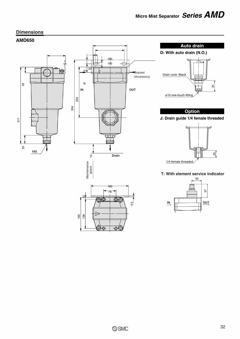
55
37
AMD650
T: With element service indicator
IN OUT
85
311
3220
180
76
160
150
20
15 11
4.5
1213
6
160
40
253
334
10M
aint
enan
cesp
ace
Drain
IN OUT
(Accessory)Bracket
Auto drainD: With auto drain (N.O.)
OptionJ: Drain guide 1/4 female threaded
20
1/4 female threaded
34
Drain cock: Black
ø10 one-touch fitting
Dimensions
Micro Mist Separator Series AMD
32
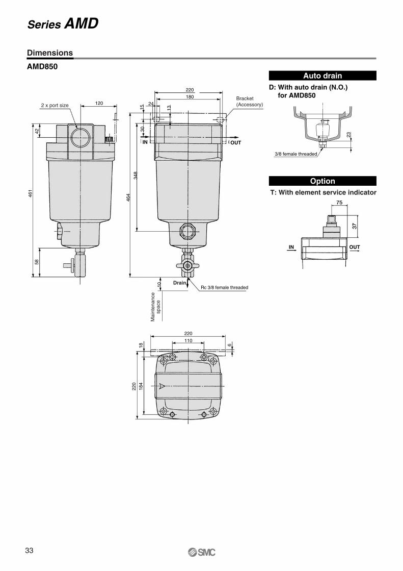
AMD850
T: With element service indicator
Auto drainD: With auto drain (N.O.)
for AMD850
Option
23
3/8 female threaded
Dimensions
Series AMD
OUTIN
120
4246
158
2 x port size
220
110
61818
4
220
220
18024
131530
348
464
10 Rc 3/8 female threaded
Mai
nten
ance
spac
e
Drain
Bracket(Accessory)
IN OUT
33
Max
. air
flow
rat
e (m
3 /m
in (
AN
R))
Inlet pressure (MPa)
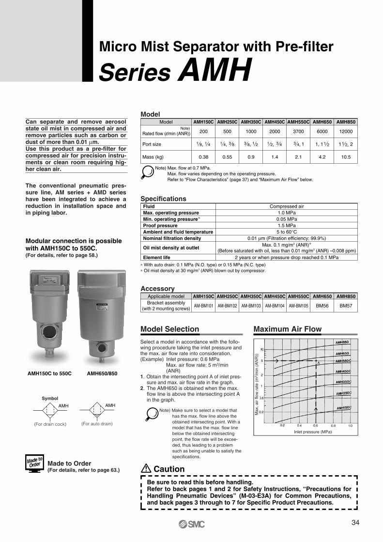
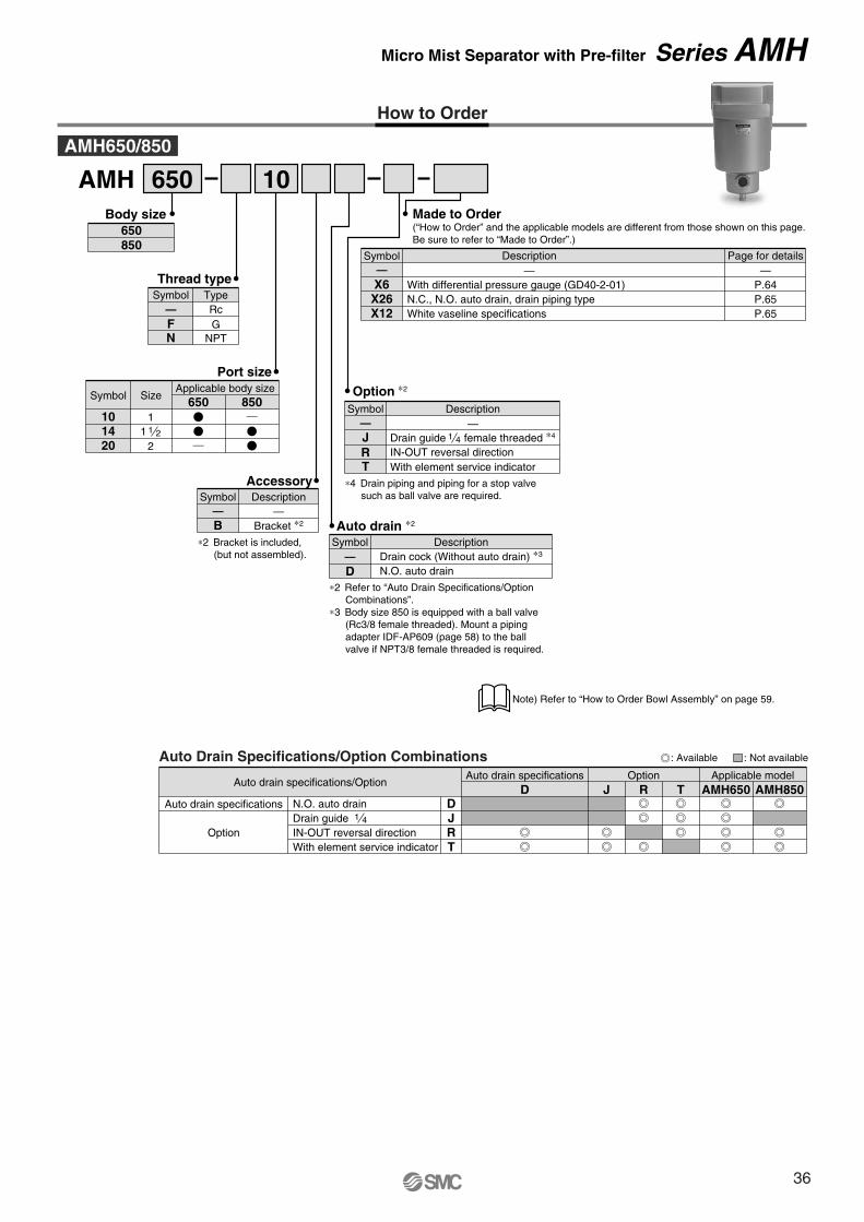
Micro Mist Separator with Pre-filter
Series AMHCan separate and remove aerosol state oil mist in compressed air and remove particles such as carbon or dust of more than 0.01 μm. Use this product as a pre-filter for compressed air for precision instru-ments or clean room requiring hig-her clean air.
The conventional pneumatic pres-sure line, AM series + AMD series have been integrated to achieve a reduction in installation space and in piping labor.
Model
Port size
Mass (kg)
Model
200
AMH150C
500
AMH250C
1000
AMH350C
2000
AMH450C
3700
AMH550C
6000
AMH650
12000
0.38 0.55 0.9 1.4 2.1 4.2 10.5
AMH850
Note) Max. flow at 0.7 MPa. Max. flow varies depending on the operating pressure.Refer to “Flow Characteristics” (page 37) and “Maximum Air Flow” below.
1 8, 1 4 1 4, 3 8 3 8, 1 2 1 2, 3 4 13 4,
Specifications
0.05 MPa1.5 MPa
FluidMax. operating pressureMin. operating pressure∗Proof pressureAmbient and fluid temperatureNominal filtration density
Element life
Compressed air1.0 MPa
5 to 60°C0.01 μm (Filtration efficiency: 99.9%)
Oil mist density at outlet Max. 0.1 mg/m3 (ANR)∗(Before saturated with oil, less than 0.01 mg/m3 (ANR) ≈0.008 ppm)
2 years or when pressure drop reached 0.1 MPa
∗ With auto drain: 0.1 MPa (N.O. type) or 0.15 MPa (N.C. type)∗ Oil mist density at 30 mg/m3 (ANR) blown out by compressor.
Maximum Air FlowModel Selection
Select a model in accordance with the follo-wing procedure taking the inlet pressure and the max. air flow rate into consideration.(Example) Inlet pressure: 0.6 MPa
Max. air flow rate: 5 m3/min (ANR)
1. Obtain the intersecting point A of inlet pres-sure and max. air flow rate in the graph.
2. The AMH650 is obtained when the max. flow line is above the intersecting point A in the graph.
AccessoryAMH150C AMH250C AMH350C AMH450C AMH550C AMH650 AMH850
AM-BM101 AM-BM102 AM-BM103 AM-BM104 AM-BM105 BM56 BM57
Applicable modelBracket assembly
(with 2 mounting screws)
Modular connection is possible with AMH150C to 550C.(For details, refer to page 58.)
AMH650/850AMH150C to 550C
Made to Order (For details, refer to page 63.)
Rated flow (l/min (ANR))Note)
11, 1 2 1 21 2,
Note) Make sure to select a model that has the max. flow line above the obtained intersecting point. With a model that has the max. flow line below the obtained intersecting point, the flow rate will be excee-ded, thus leading to a problem such as being unable to satisfy the specifications.
CautionBe sure to read this before handling.Refer to back pages 1 and 2 for Safety Instructions, “Precautions for Handling Pneumatic Devices” (M-03-E3A) for Common Precautions, and back pages 3 through to 7 for Specific Product Precautions.
Symbol
AMH
(For drain cock)
AMH
(For auto drain)
34
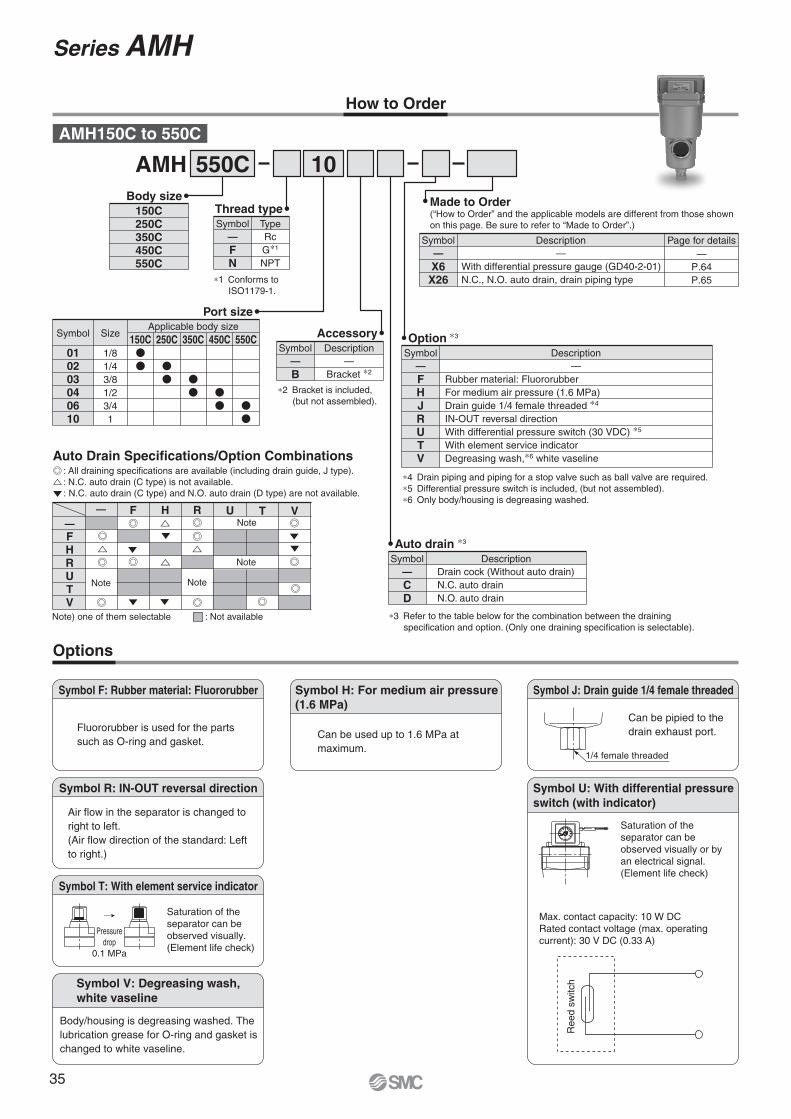
How to Order
Options
Symbol T: With element service indicator
Pressuredrop
0.1 MPa
Symbol F: Rubber material: Fluororubber
Fluororubber is used for the parts such as O-ring and gasket.
Symbol R: IN-OUT reversal direction
Air flow in the separator is changed to right to left. (Air flow direction of the standard: Left to right.)
Symbol V: Degreasing wash,white vaseline
SMCMPa
0.2
0.150.1
.05
AMH 550C 10AMH150C to 550C
Body size150C250C350C450C550C
Thread type
FN
RcG∗1
NPT
Symbol—
Type
∗1 Conforms to ISO1179-1.
Port size
010203040610
1/81/43/81/23/41
Symbol Size150C
Applicable body size250C 350C 450C 550C
Auto drain ∗3
CD
Drain cock (Without auto drain)N.C. auto drainN.O. auto drain
Symbol—
Description
Made to Order(“How to Order” and the applicable models are different from those shown on this page. Be sure to refer to “Made to Order”.)
Accessory
B—
Bracket ∗2
Symbol—
DescriptionOption ∗3
FHJRUTV
Rubber material: FluororubberFor medium air pressure (1.6 MPa)Drain guide 1/4 female threaded ∗4
IN-OUT reversal directionWith differential pressure switch (30 VDC) ∗5
With element service indicatorDegreasing wash,∗6 white vaseline
Symbol— —
Description
∗4 Drain piping and piping for a stop valve such as ball valve are required.∗5 Differential pressure switch is included, (but not assembled).∗6 Only body/housing is degreasing washed.
Symbol H: For medium air pressure(1.6 MPa)
Can be used up to 1.6 MPa at maximum.
Symbol J: Drain guide 1/4 female threaded
1/4 female threaded
Can be pipied to the drain exhaust port.
Symbol U: With differential pressure switch (with indicator)
Saturation of the separator can be observed visually or by an electrical signal. (Element life check)
Max. contact capacity: 10 W DCRated contact voltage (max. operating current): 30 V DC (0.33 A)
Ree
d sw
itch
X6X26
—With differential pressure gauge (GD40-2-01)N.C., N.O. auto drain, drain piping type
Symbol—
Description Page for details—
P.64P.65
Saturation of the separator can be observed visually. (Element life check)
Body/housing is degreasing washed. The lubrication grease for O-ring and gasket is changed to white vaseline.
∗3 Refer to the table below for the combination between the draining specification and option. (Only one draining specification is selectable).
∗2 Bracket is included, (but not assembled).
Auto Drain Specifications/Option Combinations: All draining specifications are available (including drain guide, J type).: N.C. auto drain (C type) is not available.: N.C. auto drain (C type) and N.O. auto drain (D type) are not available.
Series AMH
: Not availableNote) one of them selectable
—FHRUTV
F H R— U T VNote
Note
NoteNote
35
How to Order
AMH 650 10
Description
With differential pressure gauge (GD40-2-01)N.C., N.O. auto drain, drain piping typeWhite vaseline specifications
Page for details—
P.64P.65P.65
X6X26X12
Symbol
Made to Order(“How to Order” and the applicable models are different from those shown on this page. Be sure to refer to “Made to Order”.)
——Thread type
— RcF GN NPT
TypeSymbol
Port size
101420
11 1 2
2
SizeApplicable body size
650 850Symbol
Auto drain specifications/Option
Auto drain specifications
Option
OptionAuto drain specifications
DJR
D J TRApplicable model
AMH650 AMH850N.O. auto drainDrain guideIN-OUT reversal direction
TWith element service indicator
1 4
Auto Drain Specifications/Option Combinations
AMH650/850
Body size650850
AccessoryDescription
—Bracket ∗2
Symbol
B—
∗2 Bracket is included, (but not assembled).
J Drain guide female threaded ∗4
R IN-OUT reversal directionT With element service indicator
Option ∗2
1 4
Description—
Symbol—
∗4 Drain piping and piping for a stop valve such as ball valve are required.
Auto drain ∗2
D∗2 Refer to “Auto Drain Specifications/Option
Combinations”.∗3 Body size 850 is equipped with a ball valve
(Rc3/8 female threaded). Mount a piping adapter IDF-AP609 (page 58) to the ball valve if NPT3/8 female threaded is required.
DescriptionDrain cock (Without auto drain) ∗3
N.O. auto drain
Symbol—
Note) Refer to “How to Order Bowl Assembly” on page 59.
: Available : Not available
Micro Mist Separator with Pre-filter Series AMH
36
AMH150C
AMH250C
AMH450C AMH850
AMH550C
AMH350C AMH650
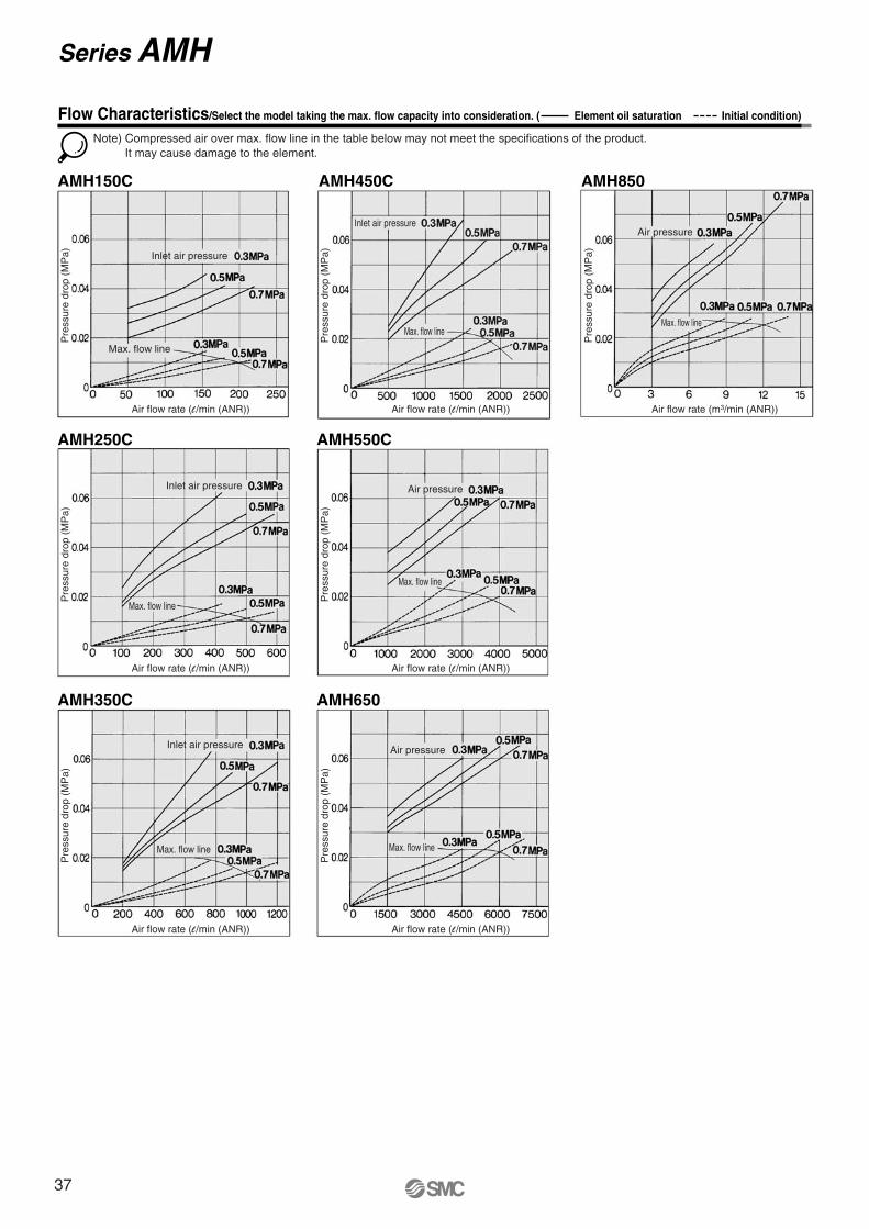
Note) Compressed air over max. flow line in the table below may not meet the specifications of the product.It may cause damage to the element.
Pre
ssur
e dr
op (
MP
a)
Air flow rate (l /min (ANR))
Pre
ssur
e dr
op (
MP
a)
Air flow rate (l /min (ANR))
Pre
ssur
e dr
op (
MP
a)
Air flow rate (l /min (ANR))
Pre
ssur
e dr
op (
MP
a)
Air flow rate (l /min (ANR))
Pre
ssur
e dr
op (
MP
a)
Air flow rate (l /min (ANR))
Pre
ssur
e dr
op (
MP
a)
Air flow rate (l /min (ANR))
Pre
ssur
e dr
op (
MP
a)
Air flow rate (m3/min (ANR))
Flow Characteristics/Select the model taking the max. flow capacity into consideration. ( Element oil saturation Initial condition)
Inlet air pressure
Inlet air pressure
Inlet air pressure
Inlet air pressureAir pressure
Air pressure
Air pressure
Series AMH
Max. flow line
Max. flow line Max. flow line
Max. flow lineMax. flow line
Max. flow line
Max. flow line
37
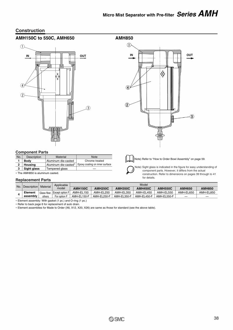
AMH150C to 550C, AMH650 AMH850
OUTIN
q
r
w
e
Replacement Parts
∗ Element assembly: With gasket (1 pc.) and O-ring (1 pc.)∗ Refer to back page 6 for replacement of auto drain.∗ Element assemblies for Made to Order (X6, X12, X20, X26) are same as those for standard (see the above table).
No.
4
Description Material
Glass fiber,others
Elementassembly
AMH150CAMH-EL150AMH-EL150-F
AMH250CAMH-EL250AMH-EL250-F
AMH350CAMH-EL350AMH-EL350-F
AMH450CModel
AMH-EL450AMH-EL450-F
AMH550CAMH-EL550AMH-EL550-F
AMH650AMH-EL650
—
AMH850AMH-EL850
—
Applicablemodel
Except option FFor option F
Component PartsNo.
23
1Description Material Note
Aluminum die-casted∗Aluminum die-casted
Tempered glass
Chrome treatedEpoxy coating on inner surface
—HousingBody
Sight glass∗ The AMH850 is aluminum casted.
Construction
Note) Sight glass is indicated in the figure for easy understanding of component parts. However, it differs from the actual construction. Refer to dimensions on pages 39 through to 41 for details.
Note) Refer to “How to Order Bowl Assembly” on page 59.
OUTIN
Micro Mist Separator with Pre-filter Series AMH
38
ø10 one-touch fitting
34
Drain cockGray: N.C.Black: N.O.
20
1/4 female threaded
Z
Y
IN OUT
W
X
IN OUT
M
øV
Drain
IN OUT
(Accessory)Bracket
G
U
DI
LT
KJ
C
H
Mai
nten
ance
spac
e
R S
PQ
OF
M5
A
EB
N
20
1/4 female threaded
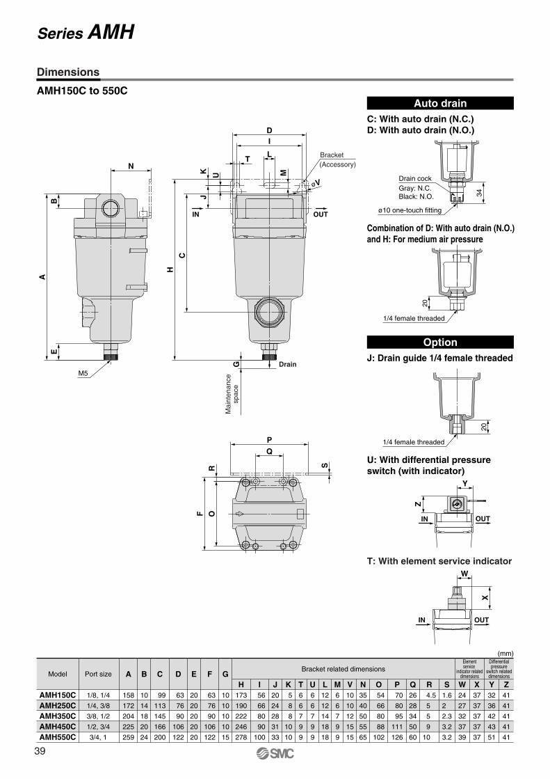
AMH150C to 550C
(mm)
AMH150CAMH250CAMH350CAMH450CAMH550C
AModel Port sizeBracket related dimensions
Elementservice
indicator relateddimensions
Differentialpressure
switch relateddimensions
158
172
204
225
259
1/8, 1/4
1/4, 3/8
3/8, 1/2
1/2, 3/4
3/4, 1
B
10
14
18
20
24
C
99
113
145
166
200
D
63
76
90
106
122
E
20
20
20
20
20
F
63
76
90
106
122
G
10
10
10
10
15
H173
190
222
246
278
I 56
66
80
90
100
J20
24
28
31
33
K 5
8
8
10
10
T6
6
7
9
9
U6
6
7
9
9
L12
12
14
18
18
M6
6
7
9
9
V10
10
12
15
15
N35
40
50
55
65
O 54
66
80
88
102
P 70
80
95
111
126
Q26
28
34
50
60
R 4.5
5
5
9
10
S1.6
2
2.3
3.2
3.2
W24
27
32
37
39
X37
37
37
37
37
Y32
36
42
43
51
Z41
41
41
41
41
Auto drainC: With auto drain (N.C.)D: With auto drain (N.O.)
OptionJ: Drain guide 1/4 female threaded
Combination of D: With auto drain (N.O.) and H: For medium air pressure
U: With differential pressure switch (with indicator)
T: With element service indicator
Series AMH
Dimensions
39
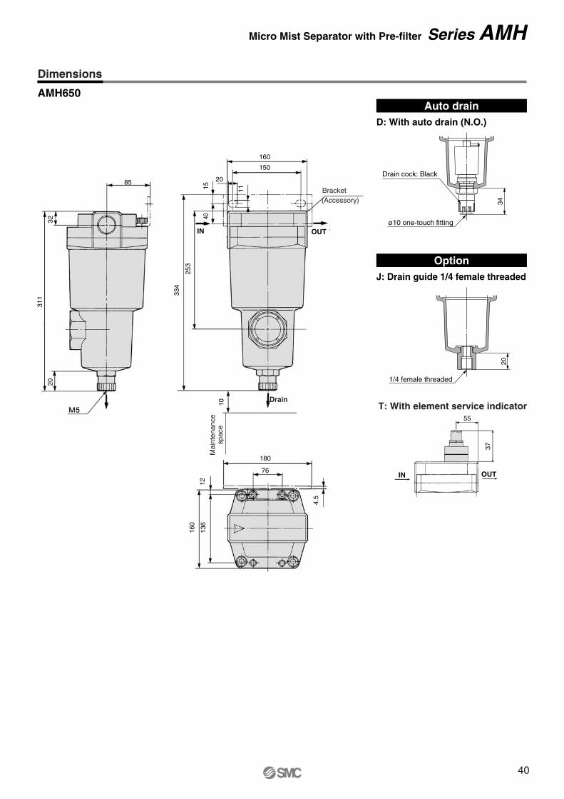
55
37
AMH650
T: With element service indicator
Auto drainD: With auto drain (N.O.)
OptionJ: Drain guide 1/4 female threaded
20
1/4 female threaded
34
Drain cock: Black
ø10 one-touch fitting
Dimensions
Micro Mist Separator with Pre-filter Series AMH
85
32
311
20
180
76
160
150
20
15
4.5
1213
6
160
40
253
334
10
11
Mai
nten
ance
spac
e
Drain
(Accessory)Bracket
IN OUT
IN OUT
40
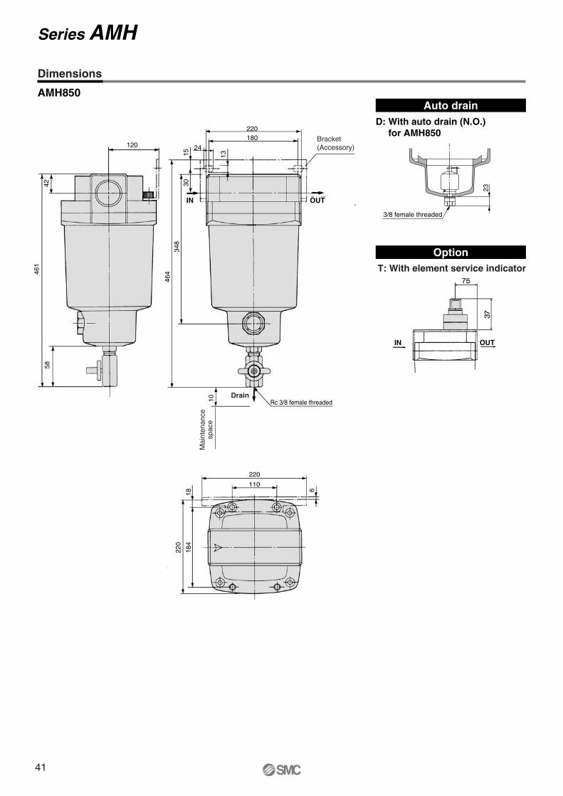
120
42
461
58
AMH850Auto drain
D: With auto drain (N.O.)for AMH850
T: With element service indicator
Option
23
3/8 female threaded
Dimensions
Series AMH
Mai
nten
ance
spac
e
220
110
220180
24
61818
4
220
131530
348
464
10 Rc 3/8 female threadedDrain
Bracket(Accessory)
IN OUT
IN OUT
41
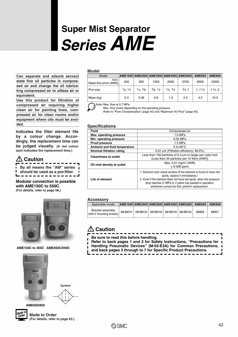
Symbol
AME
Can separate and adsorb aerosol state fine oil particles in compres-sed air and change the oil lubrica-ting compressed air to oilless air or equivalent. Use this product for filtration of compressed air requiring higher clean air for painting lines, com-pressed air for clean rooms and/or equipment where oils must be avoi-ded.
Indicates the filter element life by a colour change. Accor-dingly, the replacement time can be judged visually. (A red colour spot indicates the replacement time.)
Model
Port size
Mass (kg)
Model
200
AME150C
500
AME250C
1000
AME350C
2000
AME450C
3700
AME550C
6000
AME650
12000
0.3 0.48 0.8 1.3 2.0 4.2 10.5
AME850
Note) Max. flow at 0.7 MPa. Max. flow varies depending on the operating pressure.Refer to “Flow Characteristics” (page 45) and “Maximum Air Flow” (page 45).
1 8, 1 4 1 4, 3 8 3 8, 1 2 1 2, 3 4 13 4,
Specifications
0.05 MPa1.5 MPa
Compressed air1.0 MPa
5 to 60°C0.01 μm (Filtration efficiency: 99.9%)
Less than 100 particles of 0.3 μm or larger per cubic foot[Less than 35 particles per 10 liters (ANR)]
FluidMax. operating pressureMin. operating pressureProof pressureAmbient and fluid temperatureNominal filtration rating
Life of element
Cleanliness at outlet
Oil mist density at outlet Max. 0.01 mg/m3 (ANR)(≈0.008 ppm)
Super Mist Separator
Series AME
AccessoryAME150C AME250C AME350C AME450C AME550C AME650 AME850
AM-BM101 AM-BM102 AM-BM103 AM-BM104 AM-BM105 BM56 BM57
Applicable model
Bracket assembly(with 2 mounting screws)
CautionBy all means the “AM” series should be used as a pre-filter.
Modular connection is possible with AME150C to 550C.(For details, refer to page 58.)
AME150C to 350C AME450C/550C
AME650/850
11, 1 2 1 21 2,
Rated flow (l/min (ANR))Note)
Made to Order (For details, refer to page 63.)
CautionBe sure to read this before handling.Refer to back pages 1 and 2 for Safety Instructions, “Precautions for Handling Pneumatic Devices” (M-03-E3A) for Common Precautions, and back pages 3 through to 7 for Specific Product Precautions.
1. Element color check window (If the element is found to have red spots, replace it immediately.)
2. Even if the element does not have red spots, when the pressure drop reaches 0.1MPa or 2 years has passed in operation,
whichever comes the first, perform replacement.
42

How to Order
AME 550C 10
Options
Symbol F: Rubber material: Fluororubber
Fluororubber is used for the parts such as O-ring and gasket.
Body size150C250C350C450C550C
AME150C to 550C
Thread type
FN
RcG∗1
NPT
Symbol—
Type
∗1 Conforms to ISO1179-1.
Option
FHRV
Rubber material: FluororubberFor medium air pressure (1.6 MPa)IN-OUT reversal directionDegreasing wash,∗3 white vaseline
Symbol— —
Description
∗3 Only body/housing is degreasing washed.
Port size
010203040610
1/81/43/81/23/41
Symbol Size150C
Applicable body size250C 350C 450C 550C
Accessory
B—
Bracket ∗2
Symbol—
Description
∗2 Bracket is included, (but not assembled).
Symbol H: For medium air pressure(1.6 MPa)
Can be used up to 1.6 MPa at maximum.
Symbol R: IN-OUT reversal direction
Air flow in the separator is changed to right to left. (Air flow direction of the standard: Left to right.)
Symbol V: Degreasing wash,white vaseline
Body/housing is degreasing washed. The lubrication grease for O-ring and gasket is changed to white vaseline.
Series AME
43
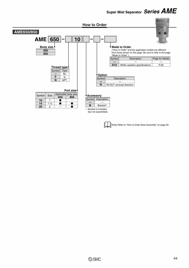
How to Order
AME 650 10
Option
R IN-OUT reversal direction
Symbol Description— —
——Description
White vaseline specifications
Page for details—
P.65X12
Symbol
Made to Order(“How to Order” and the applicable models are different from those shown on this page. Be sure to refer to the page “Made to Order”.)
Thread type
— RcF GN NPT
TypeSymbol
1014
Port size
11 1 2
20 2
650 850Symbol Size
Applicable body size
Body size650850
Accessory
B—
Bracket∗
Symbol—
Description
∗ Bracket is included, (but not assembled).
AME650/850
Note) Refer to “How to Order Bowl Assembly” on page 59.
Super Mist Separator Series AME
44
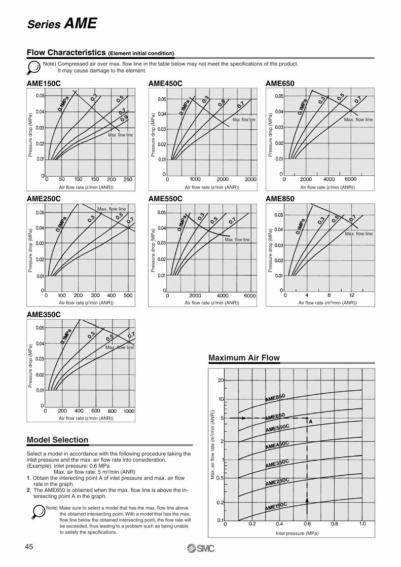
AME150C AME450C AME650
AME250C
AME350C
AME550C AME850
Model Selection
Select a model in accordance with the following procedure taking the inlet pressure and the max. air flow rate into consideration.(Example) Inlet pressure: 0.6 MPa
Max. air flow rate: 5 m3/min (ANR)1. Obtain the interecting point A of inlet pressure and max. air flow
rate in the graph.2. The AME650 is obtained when the max. flow line is above the in-
tersecting point A in the graph.
Maximum Air Flow
Note) Compressed air over max. flow line in the table below may not meet the specifications of the product.It may cause damage to the element.
Pre
ssur
e dr
op (
MP
a)
Pre
ssur
e dr
op (
MP
a)
Pre
ssur
e dr
op (
MP
a)
Flow Characteristics (Element initial condition)
Air flow rate (l /min (ANR)) Air flow rate (l /min (ANR)) Air flow rate (l /min (ANR))
Pre
ssur
e dr
op (
MP
a)
Pre
ssur
e dr
op (
MP
a)
Pre
ssur
e dr
op (
MP
a)
Air flow rate (l /min (ANR))
Pre
ssur
e dr
op (
MP
a)
Air flow rate (l /min (ANR))
Air flow rate (l /min (ANR)) Air flow rate (m3/min (ANR))
Max
. air
flow
rat
e (m
3 /m
in (
AN
R))
Inlet pressure (MPa)
Note) Make sure to select a model that has the max. flow line above the obtained intersecting point. With a model that has the max. flow line below the obtained intersecting point, the flow rate will be exceeded, thus leading to a problem such as being unable to satisfy the specifications.
Series AME
Max. flow line
Max. flow line
Max. flow line
Max. flow line
Max. flow line
Max. flow line
Max. flow line
45
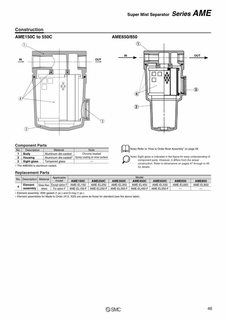
Replacement Parts
∗ Element assembly: With gasket (1 pc.) and O-ring (1 pc.)∗ Element assemblies for Made to Order (X12, X20) are same as those for standard (see the above table).
No.
4
Description Material
Glass fiber,others
Elementassembly
AME150CAME-EL150
AME-EL150-F
AME250CAME-EL250
AME-EL250-F
AME350CAME-EL350
AME-EL350-F
AME450CModel
AME-EL450AME-EL450-F
AME550CAME-EL550
AME-EL550-F
AME650AME-EL650
—
AME850AME-EL850
—
Applicablemodel
Except option FFor option F
AME150C to 550C AME650/850
Component PartsNo.
23
1Description Material Note
Aluminum die-casted∗Aluminum die-casted
Tempered glass
Chrome treatedEpoxy coating on inner surface
—HousingBody
Sight glass∗ The AME850 is aluminum casted.
r
e
w
q
IN OUT
Construction
Note) Sight glass is indicated in the figure for easy understanding of component parts. However, it differs from the actual construction. Refer to dimensions on pages 47 through to 49 for details.
Note) Refer to “How to Order Bowl Assembly” on page 59.
IN OUT
Super Mist Separator Series AME
46
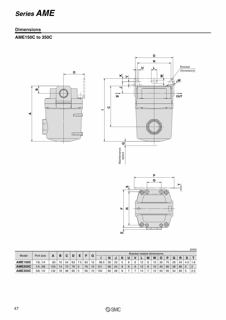
SR
TP
Q
FE
O
B
A
Bracket
OUTIN
(Accessory)
M
øW
I
J
V
D
N
LU
KG
C
Mai
nten
ance
spac
e
AME150C to 350C
(mm)
AME150CAME250CAME350C
AModel Port sizeBracket related dimensions
83
103
132
1/8, 1/4
1/4, 3/8
3/8, 1/2
B
10
14
18
C
54
73
98
D
63
76
90
E
7.5
5
5
F
63
76
90
G
10
10
10
I 98.5
121
150
N56
66
80
J20
24
28
K5
8
8
U6
6
7
V6
6
7
L12
12
14
M6
6
7
W10
10
12
O35
40
50
P70
80
95
Q26
28
34
R54
66
80
S4.5
5
5
T1.6
2
2.3
Dimensions
Series AME
47
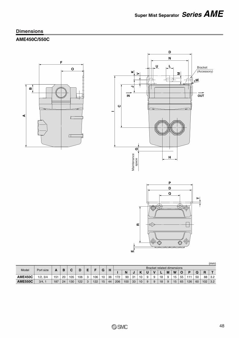
E
R
Q
P
D
T
Bracket(Accessory)
L
M
U
N
øW
V
JK
C
I
D
H
GM
aint
enan
cesp
ace
IN OUT
A
B
O
F
AME450C/550C
AME450CAME550C
AModel Port sizeBracket related dimensions
151
187
1/2, 3/4
3/4, 1
B
20
24
C
105
130
D
106
122
E
3
3
F
106
122
G
10
15
H
36
44
I172
206
N 90
100
J31
33
K10
10
U9
9
V9
9
L18
18
M9
9
W15
15
O55
65
P111
126
Q50
60
R 88
102
T3.2
3.2
(mm)
Dimensions
Super Mist Separator Series AME
48
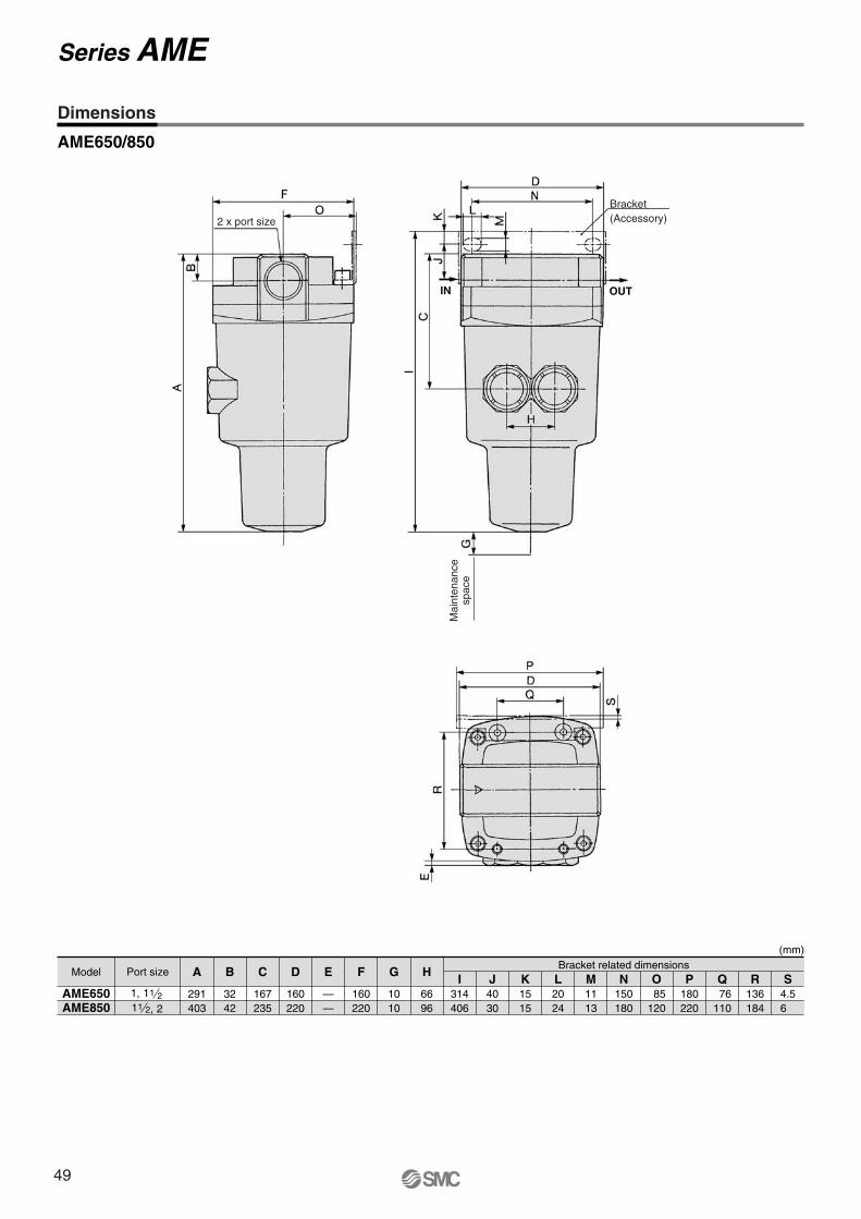
2 x port size
AME650/850
Model Port size A
291403
AME650AME850
B
3242
C
167235
D
160220
E
——
F
160220
G
1010
H
6696
I314406
J4030
K1515
L2024
MBracket related dimensions
1113
N150180
O 85120
P180220
Q 76110
R136184
S4.56
1 21,2
11 2,1
(mm)
Dimensions
Series AME
Mai
nten
ance
spac
e
Bracket(Accessory)
IN OUT
49
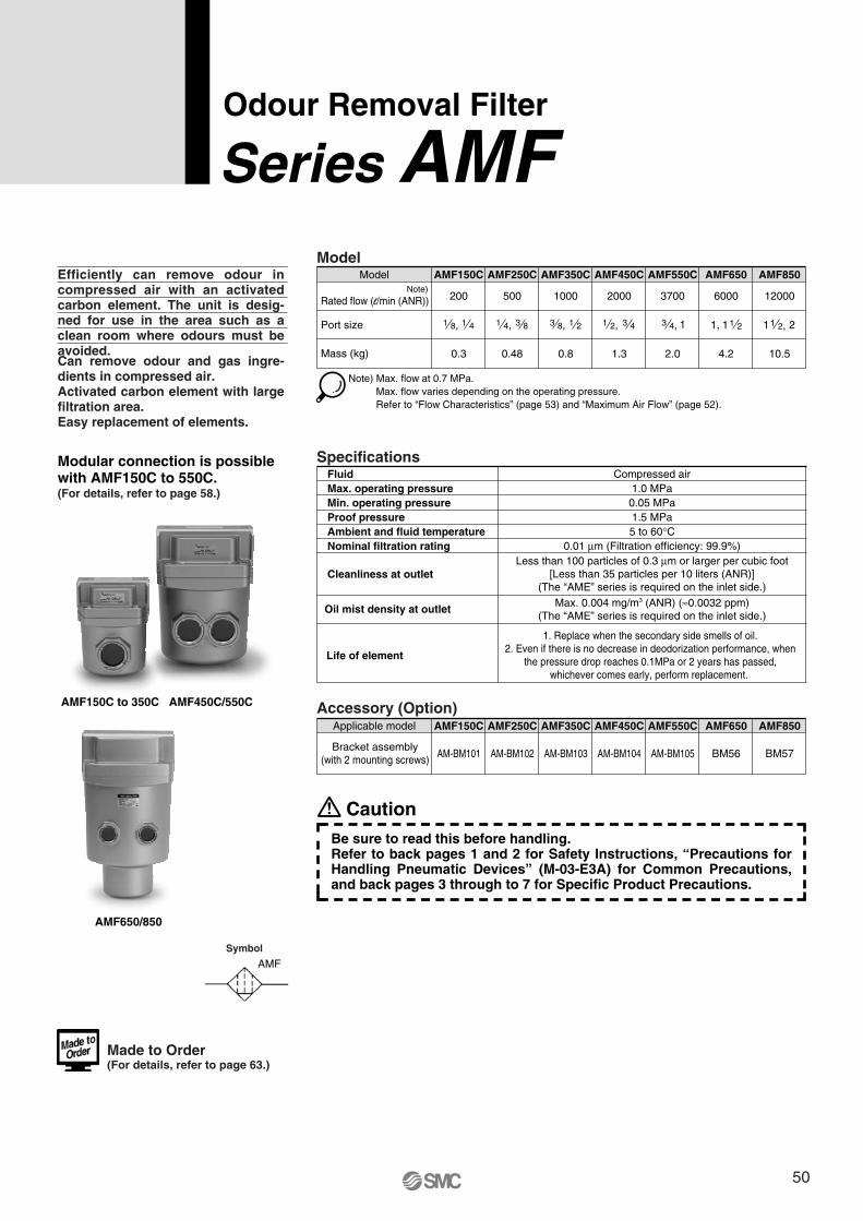
Symbol
AMF
Odour Removal Filter
Series AMFEfficiently can remove odour in compressed air with an activated carbon element. The unit is desig-ned for use in the area such as a clean room where odours must be avoided.Can remove odour and gas ingre-dients in compressed air.Activated carbon element with large filtration area.Easy replacement of elements.
Accessory (Option)
Model
1 8, 1 4 1 4, 3 8 3 8, 1 2 1 2, 3 4Port size
Mass (kg)
Model
200
AMF150C
500
AMF250C
1000
AMF350C
2000
AMF450C
3700
AMF550C
6000
AMF650
12000
0.3 0.48 0.8 1.3 2.0 4.2 10.5
AMF850
Note) Max. flow at 0.7 MPa. Max. flow varies depending on the operating pressure.Refer to “Flow Characteristics” (page 53) and “Maximum Air Flow” (page 52).
13 4,
SpecificationsFluidMax. operating pressureMin. operating pressureProof pressureAmbient and fluid temperatureNominal filtration rating
Cleanliness at outlet
Oil mist density at outlet
Life of element
0.05 MPa1.5 MPa
Compressed air1.0 MPa
5 to 60°C0.01 μm (Filtration efficiency: 99.9%)
Less than 100 particles of 0.3 μm or larger per cubic foot[Less than 35 particles per 10 liters (ANR)]
(The “AME” series is required on the inlet side.)
Max. 0.004 mg/m3 (ANR) (≈0.0032 ppm)(The “AME” series is required on the inlet side.)
AMF150C AMF250C AMF350C AMF450C AMF550C AMF650 AMF850
AM-BM101 AM-BM102 AM-BM103 AM-BM104 AM-BM105 BM56 BM57
Applicable model
Bracket assembly(with 2 mounting screws)
Modular connection is possible with AMF150C to 550C.(For details, refer to page 58.)
AMF150C to 350C AMF450C/550C
AMF650/850
11, 1 2 1 21 2,
Rated flow (l/min (ANR))Note)
Made to Order(For details, refer to page 63.)
CautionBe sure to read this before handling.Refer to back pages 1 and 2 for Safety Instructions, “Precautions for Handling Pneumatic Devices” (M-03-E3A) for Common Precautions, and back pages 3 through to 7 for Specific Product Precautions.
1. Replace when the secondary side smells of oil.2. Even if there is no decrease in deodorization performance, when
the pressure drop reaches 0.1MPa or 2 years has passed, whichever comes early, perform replacement.
50
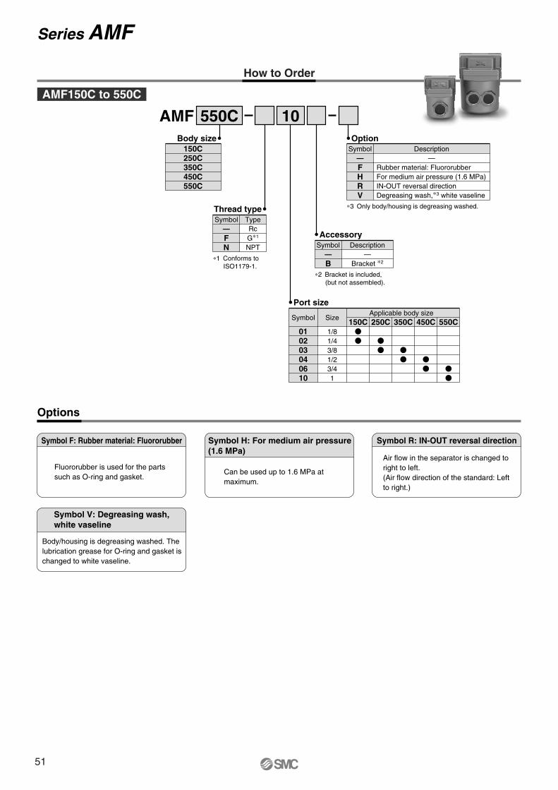
How to Order
AMF 550C 10
Options
Body size150C250C350C450C550C
Thread type
FN
RcG∗1
NPT
Symbol—
Type
∗1 Conforms to ISO1179-1.
Option
FHRV
Rubber material: FluororubberFor medium air pressure (1.6 MPa)IN-OUT reversal directionDegreasing wash,∗3 white vaseline
Symbol— —
Description
∗3 Only body/housing is degreasing washed.
Port size
010203040610
1/81/43/81/23/41
Symbol Size150C
Applicable body size250C 350C 450C 550C
AMF150C to 550C
Accessory
B—
Bracket ∗2
Symbol—
Description
∗2 Bracket is included, (but not assembled).
Symbol F: Rubber material: Fluororubber
Fluororubber is used for the parts such as O-ring and gasket.
Symbol H: For medium air pressure(1.6 MPa)
Can be used up to 1.6 MPa at maximum.
Symbol R: IN-OUT reversal direction
Air flow in the separator is changed to right to left. (Air flow direction of the standard: Left to right.)
Symbol V: Degreasing wash,white vaseline
Body/housing is degreasing washed. The lubrication grease for O-ring and gasket is changed to white vaseline.
Series AMF
51
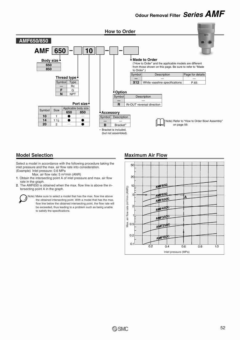
How to Order
Max
. air
flow
rat
e (m
3 /m
in (
AN
R))
Inlet pressure (MPa)
Maximum Air FlowModel Selection
Select a model in accordance with the following procedure taking the inlet pressure and the max. air flow rate into consideration.(Example) Inlet pressure: 0.6 MPa
Max. air flow rate: 5 m3/min (ANR)1. Obtain the intersecting point A of inlet pressure and max. air flow
rate in the graph.2. The AMF650 is obtained when the max. flow line is above the in-
tersecting point A in the graph.
AMF 650 10
Thread type
— RcF GN NPT
TypeSymbol
Option
R IN-OUT reversal direction
Symbol Description— —
Port size
101420
11 1 2
2
SizeApplicable body size
650 850Symbol
Symbol
X12
Page for details
P.65——
Description
White vaseline specifications—
Made to Order(“How to Order” and the applicable models are different from those shown on this page. Be sure to refer to “Made to Order”.)
AMF650/850
Body size650850
Accessory
B—
Bracket∗
Symbol—
Description
∗ Bracket is included, (but not assembled).
Note) Refer to “How to Order Bowl Assembly” on page 59.
Note) Make sure to select a model that has the max. flow line above the obtained intersecting point. With a model that has the max. flow line below the obtained intersecting point, the flow rate will be exceeded, thus leading to a problem such as being unable to satisfy the specifications.
Odour Removal Filter Series AMF
52
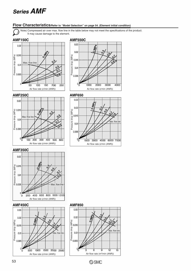
AMF150C AMF550C
AMF250C AMF650
AMF350C
AMF450C AMF850
Note) Compressed air over max. flow line in the table below may not meet the specifications of the product.It may cause damage to the element.
Flow Characteristics/Refer to “Model Selection” on page 54. (Element initial condition)
Series AMF
Max. flow line
Max. flow line
Max. flow line
Max. flow lineMax. flow line
Max. flow line
Pre
ssur
e dr
op (
MP
a)
Air flow rate (l /min (ANR))
Pre
ssur
e dr
op (
MP
a)
Air flow rate (l /min (ANR))
Pre
ssur
e dr
op (
MP
a)
Air flow rate (l /min (ANR))
Pre
ssur
e dr
op (
MP
a)
Air flow rate (l /min (ANR))
Pre
ssur
e dr
op (
MP
a)
Air flow rate (l /min (ANR))
Pre
ssur
e dr
op (
MP
a)
Air flow rate (l /min (ANR))
Pre
ssur
e dr
op (
MP
a)
Air flow rate (m3/min (ANR))
53
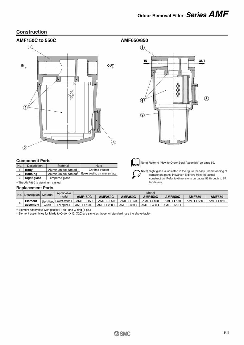
AMF150C to 550C AMF650/850
Replacement Parts
∗ Element assembly: With gasket (1 pc.) and O-ring (1 pc.)∗ Element assemblies for Made to Order (X12, X20) are same as those for standard (see the above table).
No.
4
Description Material
Glass fiber,others
Elementassembly
AMF150CAMF-EL150
AMF-EL150-F
AMF250CAMF-EL250
AMF-EL250-F
AMF350CAMF-EL350
AMF-EL350-F
AMF450CModel
AMF-EL450AMF-EL450-F
AMF550CAMF-EL550
AMF-EL550-F
AMF650AMF-EL650
—
AMF850AMF-EL850
—
Applicablemodel
Except option FFor option F
r
ew
q
IN OUT
Component PartsNo.123
Description NoteMaterial
Aluminum die-casted∗Aluminum die-casted
Tempered glass
Chrome treatedEpoxy coating on inner surface
—HousingBody
Sight glass∗ The AMF850 is aluminum casted.
Construction
Note) Sight glass is indicated in the figure for easy understanding of component parts. However, it differs from the actual construction. Refer to dimensions on pages 55 through to 57 for details.
Note) Refer to “How to Order Bowl Assembly” on page 59.
IN OUT
Odour Removal Filter Series AMF
54
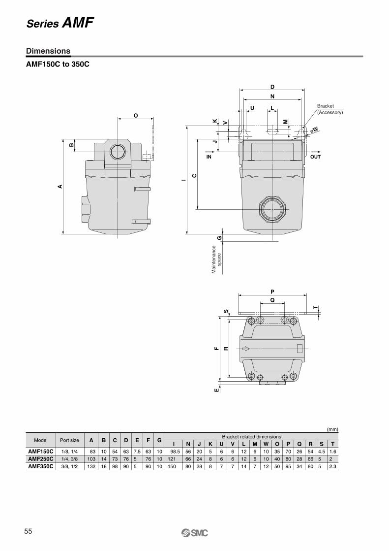
O
B
A
SR
T
P
Q
FE
Bracket
OUTIN
(Accessory)
M
øW
I
J
V
D
N
LU
KG
C
Mai
nten
ance
spac
e
AMF150C to 350C
(mm)
AMF150CAMF250CAMF350C
AModel Port sizeBracket related dimensions
83
103
132
1/8, 1/4
1/4, 3/8
3/8, 1/2
B
10
14
18
C
54
73
98
D
63
76
90
E
7.5
5
5
F
63
76
90
G
10
10
10
I 98.5
121
150
N56
66
80
J20
24
28
K5
8
8
U6
6
7
V6
6
7
L12
12
14
M6
6
7
W10
10
12
O35
40
50
P70
80
95
Q26
28
34
R54
66
80
S4.5
5
5
T1.6
2
2.3
Dimensions
Series AMF
55
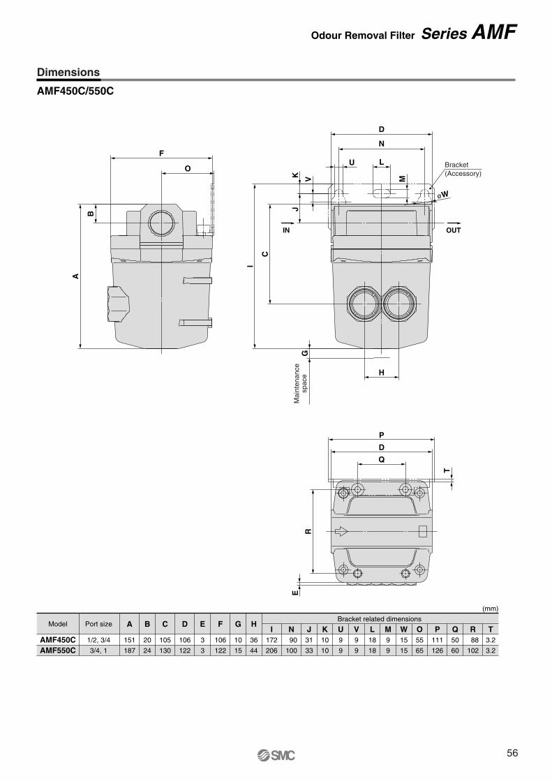
A
B
O
FBracket(Accessory)
L
M
U
N
øW
V
JK
C
I
D
H
GM
aint
enan
cesp
ace
IN OUT
E
R
Q
P
DT
AMF450C/550C
(mm)
AMF450CAMF550C
AModel Port sizeBracket related dimensions
151
187
1/2, 3/4
3/4, 1
B
20
24
C
105
130
D
106
122
E
3
3
F
106
122
G
10
15
H
36
44
I172
206
N 90
100
J31
33
K10
10
U9
9
V9
9
L18
18
M9
9
W15
15
O55
65
P111
126
Q50
60
R 88
102
T3.2
3.2
Dimensions
Odour Removal Filter Series AMF
56

2 x port size
AMF650/850
Model Port size A
291403
AMF650AMF850
B
3242
C
167235
D
160220
E
——
F
160220
G
1010
H
6696
I314406
J4030
K1515
L2024
MBracket related dimensions
1113
N150180
O 85120
P180220
Q 76110
R136184
S4.56
1 21,2
11 2,1
(mm)
Dimensions
Series AMF
Mai
nten
ance
spac
e
Bracket(Accessory)
IN OUT
57
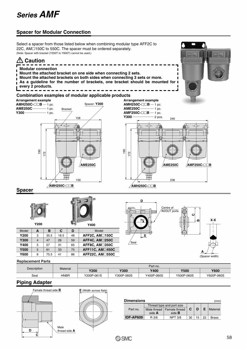
Spacer for Modular Connection
Spacer
Y200
Replacement Parts
Description
Seal
Material
HNBR
Y200Y200P-061S
Y300Y300P-060S
Y400Y400P-060S
Y500Y500P-060S
Y600Y600P-060S
Part no.
Y400
A(Spacer width)
X-X
D
Seal
Centre ofIN/OUT ports
X
X
B
C
REL
EASE
1
2
Combination examples of modular applicable products
Select a spacer from those listed below when combining modular type AFF2C to 22C, AM�150C to 550C. The spacer must be ordered separately.
Y200Y300Y400Y500Y600
AFF2C, AM�150CAFF4C, AM�250CAFF8C, AM�350CAFF11C, AM�450CAFF22C, AM�550C
3
4
5
5
6
35.5
47
57
61
75.5
18.5
26
31
33
41
48
59
65
75
86
Model ModelA B C D
17219
0
156
158
Bracket
Spacer: Y300
AMH250C-��B
AME250C
(Note: Spacer with bracket (Y200T to Y600T) cannot be used.)
CautionModular connectionMount the attached bracket on one side when connecting 2 sets.Mount the attached brackets on both sides when connecting 3 sets or more.As a guideline for the number of brackets, one bracket should be mounted for every 2 products.
190
172
236
240
AMH250C-��B
AME250C AMF250C-��B
Arrangement exampleAMH250C-��B 1 pc.AME250C 1 pc.Y300 1 pc.
Arrangement exampleAMH250C-��B 1 pc.AME250C 1 pc.AMF250C-��B 1 pc.Y300 2 pcs.
Series AMF
Part no. Material
IDF-AP609
Thread type and port sizeMale thread
side AFemale thread
side BR 3/8 NPT 3/8
C
30
D E
Brass
(mm)
15 22
Dimensions
Piping Adapter
E (Width across flats)
DC
Male thread side A
Female thread side B
58
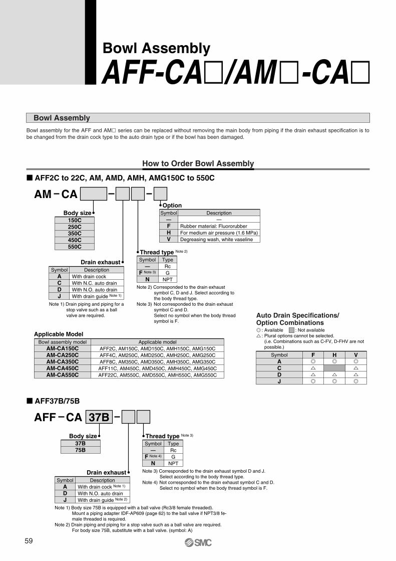
Bowl Assembly
AFF-CA�/AM�-CA�Bowl assembly for the AFF and AM� series can be replaced without removing the main body from piping if the drain exhaust specification is to be changed from the drain cock type to the auto drain type or if the bowl has been damaged.
How to Order Bowl Assembly
� AFF2C to 22C, AM, AMD, AMH, AMG150C to 550C
� AFF37B/75B
AM CAOption
Symbol—FHV
Description—
Rubber material: FluororubberFor medium air pressure (1.6 MPa)Degreasing wash, white vaseline
150C250C350C450C550C
Body size
Bowl Assembly
Drain exhaustSymbol
ACDJ
Description
Note 1) Drain piping and piping for a stop valve such as a ball valve are required.
Thread type Note 2)
Symbol—
F Note 3)
N
TypeRcG
NPT
AFF 37BCA
Applicable ModelBowl assembly model
AM-CA150CAM-CA250CAM-CA350CAM-CA450CAM-CA550C
Applicable modelAFF2C, AM150C, AMD150C, AMH150C, AMG150CAFF4C, AM250C, AMD250C, AMH250C, AMG250CAFF8C, AM350C, AMD350C, AMH350C, AMG350C
AFF11C, AM450C, AMD450C, AMH450C, AMG450CAFF22C, AM550C, AMD550C, AMH550C, AMG550C
37B75B
Body size
Drain exhaust
Note 2) Corresponded to the drain exhaust symbol C, D and J. Select according to the body thread type.
Note 3) Not corresponded to the drain exhaust symbol C and D.Select no symbol when the body thread symbol is F.
SymbolADJ
Description
With drain cockWith N.C. auto drainWith N.O. auto drainWith drain guide Note 1)
With drain cock Note 1)
With N.O. auto drainWith drain guide Note 2)
Note 1) Body size 75B is equipped with a ball valve (Rc3/8 female threaded). Mount a piping adapter IDF-AP609 (page 62) to the ball valve if NPT3/8 fe-male threaded is required.
Note 2) Drain piping and piping for a stop valve such as a ball valve are required.For body size 75B, substitute with a ball valve. (symbol: A)
Thread type Note 3)
Symbol—
F Note 4)
N
TypeRcG
NPT
Note 3) Corresponded to the drain exhaust symbol D and J. Select according to the body thread type.
Note 4) Not corresponded to the drain exhaust symbol C and D.Select no symbol when the body thread symbol is F.
ACDJ
Symbol F H V
Auto Drain Specifications/Option Combinations
: Available: Plural options cannot be selected.(i.e. Combinations such as C-FV, D-FHV are not possible.)
: Not available
59
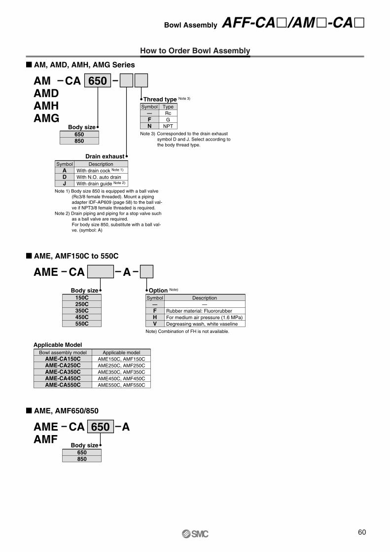
How to Order Bowl Assembly
� AM, AMD, AMH, AMG Series
AMAMDAMHAMG
650CA
650850
Body size
Drain exhaustSymbol
ADJ
Description
Note 1) Body size 850 is equipped with a ball valve (Rc3/8 female threaded). Mount a piping adapter IDF-AP609 (page 58) to the ball val-ve if NPT3/8 female threaded is required.
Note 2) Drain piping and piping for a stop valve such as a ball valve are required.For body size 850, substitute with a ball val-ve. (symbol: A)
Thread type Note 3)
Symbol—FN
TypeRcG
NPT
Note 3) Corresponded to the drain exhaust symbol D and J. Select according to the body thread type.
� AME, AMF650/850
AMEAMF
650CA A
650850
Body size
� AME, AMF150C to 550C
AME CA A
Option Note)
Symbol—FHV
Description—
With drain cock Note 1)
With N.O. auto drainWith drain guide Note 2)
Rubber material: FluororubberFor medium air pressure (1.6 MPa)Degreasing wash, white vaseline
150C250C350C450C550C
Body size
Applicable ModelBowl assembly model
AME-CA150CAME-CA250CAME-CA350CAME-CA450CAME-CA550C
Applicable modelAME150C, AMF150CAME250C, AMF250CAME350C, AMF350CAME450C, AMF450CAME550C, AMF550C
Note) Combination of FH is not available.
Bowl Assembly AFF-CA�/AM�-CA�
60
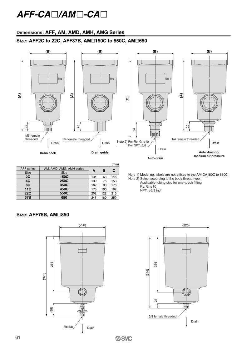
Drain guide
Drain
20
(A)
(B)
1/4 female threaded
Note 1)
Auto drain
Drain
34
(C)
(B)
Note 2) For Rc, G: ø10For NPT: 3/8
Note 1)
Drain
266
(379
)
(58)
(220)
Rc 3/8
Drain
266
(344
)
23
(220)
3/8 female threaded
Drain
Drain cock
(A)
20
(B)
M5 femalethreaded
Note 1)
Auto drain formedium air pressure
Drain
20
(A)
(B)
1/4 female threaded
Dimensions: AFF, AM, AMD, AMH, AMG Series
Size: AFF2C to 22C, AFF37B, AM�150C to 550C, AM�650
Note 1) Model no. labels are not affixed to the AM-CA150C to 550C.Note 2) Select according to the body thread type.
Applicable tubing size for one-touch fittingRc, G: ø10NPT: ø3/8 inch
Size: AFF75B, AM�850
AFF series AM, AMD, AMG, AMH seriesSize Size2C4C
11C
37B
8C
22C
A
134150C250C350C450C550C650
139162178202245
B
63 76 90106122160
C
148153176192216259
(mm)
AFF-CA�/AM�-CA�
61
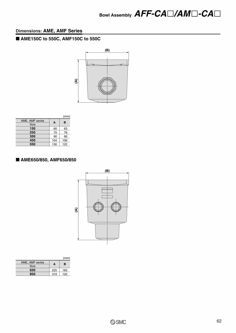
(A)
(B)
(A)
(B)
� AME150C to 550C, AMF150C to 550C
Dimensions: AME, AMF Series
AME, AMF seriesSize
A
60 70 90104130
150250350450550
B
63 76 90106122
(mm)
� AME650/850, AMF650/850
AME, AMF seriesSize
A
225319
650850
B
160120
(mm)
Bowl Assembly AFF-CA�/AM�-CA�
62
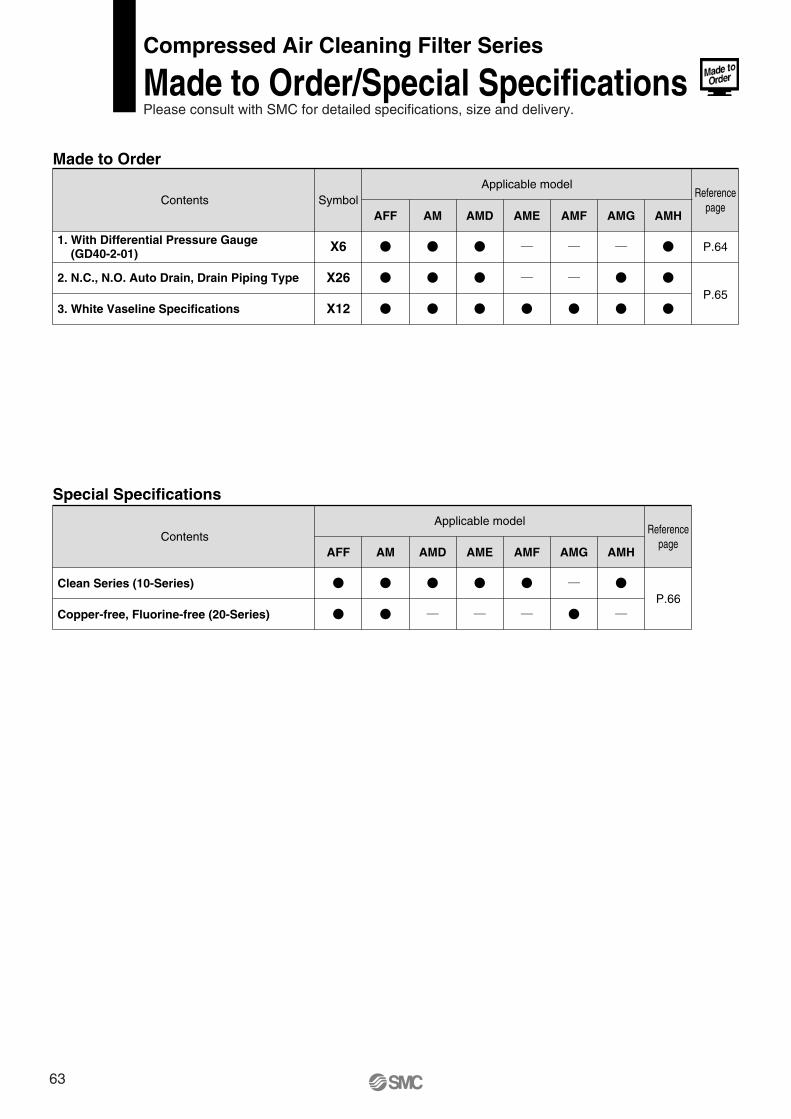
Special Specifications
Contents
Clean Series (10-Series)
Copper-free, Fluorine-free (20-Series)
Applicable model
AFF AM AMD AME AMF AMG AMH
P.66
Made to Order
Contents SymbolReference
page
Referencepage
X6
X26
X12
Applicable model
AFF AM AMD AME AMF AMG AMH
P.64
P.65
Compressed Air Cleaning Filter Series
Made to Order/Special SpecificationsPlease consult with SMC for detailed specifications, size and delivery.
1. With Differential Pressure Gauge (GD40-2-01)
2. N.C., N.O. Auto Drain, Drain Piping Type
3. White Vaseline Specifications
63
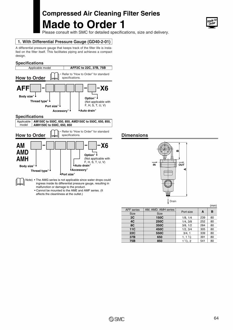
Drain
IN OUT
B
A
1. With Differential Pressure Gauge (GD40-2-01)A differential pressure gauge that keeps track of the filter life is insta-lled on the filter itself. This facilitates piping and achieves a compact design.
SpecificationsAFF2C to 22C, 37B, 75BApplicable model
How to Order
Dimensions
SpecificationsAM150C to 550C, 650, 850, AMD150C to 550C, 650, 850, AMH150C to 550C, 650, 850
Applicablemodel
How to Order
AFF X6Option∗(Not applicable with F, H, S, T, U, V)
Accessory∗Port size∗
Thread type∗Body size∗
Auto drain∗
AMAMDAMH
X6Option∗(Not applicable with F, H, S, T, U, V)
Accessory∗
Port size∗Thread type∗
Body size∗ Auto drain∗
Note) • The AMG series is not applicable since water drops could ingress inside its differential pressure gauge, resulting in malfunction or damage to the product.
• Cannot be mounted to the AME and AMF series. (It affects the cleanliness at the outlet.)
AFF seriesSize
AM, AMD, AMH seriesSize
150C250C350C450C550C650850
Port size A
239252284
B
80808080305
339 80391 80541 80
2C4C8C11C22C37B75B
1/4, 3/81/8, 1/4
3/8, 1/21/2, 3/43/4, 1
1, 11 , 2
1 21 2
(mm)
Compressed Air Cleaning Filter Series
Made to Order 1Please consult with SMC for detailed specifications, size and delivery.
∗ Refer to “How to Order” for standard specifications.
∗ Refer to “How to Order” for standard specifications.
64
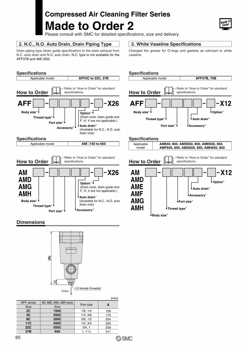
Drain
20
(A)
1/4 female threaded
3. White Vaseline SpecificationsChanged the grease for O-rings and gaskets as lubricant to white vaseline.
SpecificationsAFF37B, 75BApplicable model
How to Order
SpecificationsAM650, 850, AMD650, 850, AME650, 850,AMF650, 850, AMG650, 850, AMH650, 850
Applicablemodel
How to Order
AFF X12Option∗
Auto drain∗
Port size∗
Thread type∗
Body size∗
Accessory∗
AMAMDAMEAMFAMGAMH
X12Option∗
Auto drain∗
Port size∗
Thread type∗
Body size∗
Accessory∗
2. N.C., N.O. Auto Drain, Drain Piping TypeDrain piping type (drain guide specification) to the drain exhaust from N.C. auto drain and N.O. auto drain. N.C. type is not available for the AFF37B and AM�650.
SpecificationsAFF2C to 22C, 37BApplicable model
How to Order
SpecificationsAM�150 to 650Applicable model
How to Order
Dimensions
AFF X26Option∗(Drain cock, drain guide and F, H, V are not applicable.)
Auto drain∗(Available for N.C., N.O. auto drain only)
Port size∗Thread type∗
Body size∗
Accessory∗
AMAMDAMGAMH
X26Option∗(Drain cock, drain guide and F, H, V are not applicable.)
Port size∗Thread type∗
Body size∗Auto drain∗(Available for N.C., N.O. auto drain only)
Accessory∗
AFF seriesSize
AM, AMD, AMG, AMH seriesSize
150C250C350C450C
Port size A
159
(mm)
172204
2C4C8C11C
1/8, 1/41/4, 3/83/8, 1/2
550C22C650
225
37B
1/2, 3/42593/4, 13111, 1 1 2
∗ Refer to “How to Order” for standard specifications.
∗ Refer to “How to Order” for standard specifications.
∗ Refer to “How to Order” for standard specifications.
∗ Refer to “How to Order” for standard specifications.
Compressed Air Cleaning Filter Series
Made to Order 2Please consult with SMC for detailed specifications, size and delivery.
65
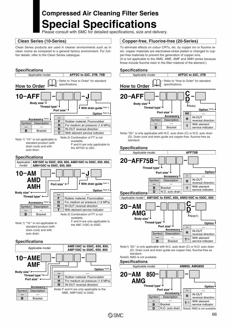
Clean Series (10-Series) Copper-free, Fluorine-free (20-Series)Clean Series products are used in cleaner environments such as in clean rooms as compared to a general factory environment. For furt-her details, refer to the Clean Series catalogue.
To eliminate effects on colour CRTs, etc. by copper ion or fluorine re-sin, copper materials are electroless-nickel plated or changed to cop-per-free materials to prevent the generation of copper ions.(It is not applicable to the AMD, AME, AMF and AMH series because those include fluorine resin in the filter material of the element.)
SpecificationsAFF2C to 22C, 37B, 75BApplicable model
∗ Refer to “How to Order” for standard specifications.How to Order
SpecificationsAFF2C to 22C, 37BApplicable model
∗ Refer to “How to Order” for standard specifications.
Note 1) “10-” is not applicable to standard product (with drain cock) and with auto drain.
Note 1) “10-” is not applicable to standard product (with drain cock) and with auto drain.
SpecificationsAM150C to 550C, 650, 850, AMD150C to 550C, 650, 850,AMH150C to 550C, 650, 850
Applicablemodel
SpecificationsAFF75BApplicable model
Note 2) Combination of FT is not available.F and H are only applicable to the AFF2C to 22C.
AFF J10
With drain guide Note 1)
Accessory Note)
Port size∗Thread type∗
Body size∗
Symbol Description—B
Option Note 2)
—FHRT
Rubber material: FluororubberFor medium air pressure (1.6 MPa)IN-OUT reversal directionWith element service indicator
—
—FHRT
Rubber material: FluororubberFor medium air pressure (1.6 MPa)IN-OUT reversal directionWith element service indicator
—
SpecificationsAME150C to 550C, 650, 850,AMF150C to 550C, 650, 850Applicable model
Note) “20-” is only applicable with N.C. auto drain (C) or N.O. auto drain (D). Drain cock and drain guide are copper-free, fluorine-free as standard.
Note1) “20-” is only applicable with N.C. auto drain (C) or N.O. auto drain (D). Drain cock and drain guide are copper-free, fluorine-free as standard.
Note2) AMG is not available.
How to Order
CD
SpecificationsAM150C to 550C, 650, AMG150C to 550C, 650Applicable model
AMAMG
20
Port size∗Thread type∗
Body size∗
Accessory
Note1)
Symbol Description—B
SpecificationsAM850, AMG850Applicable model
AMAMG
85020
Port size∗Thread type∗
AccessorySymbol Description
—BD
Note 2) Combination of FT is not available.F and H are only applicable to the AM�150C to 550C.
AMAMDAMH
10Port size∗
Thread type∗Body size∗
JWith drain guide Note 1)
Accessory Note)
Symbol Description—B
Option Note 2)
AFF CD20
Note)
Port size∗Thread type∗
Body size∗
AccessorySymbol Description
—B
Option Note)
AFF75B20
Port size∗Thread type∗
AccessorySymbol Description
—BD
Option
Option
Option
R
—
T 2)
IN-OUT reversal directionWith element service indicator
—
R
—
T 2)
IN-OUT reversal directionWith element service indicator
—
R
—
T
IN-OUT reversal directionWith element service indicator
—
R
Nil
T
IN-OUT reversal directionWith element service indicator
—
Compressed Air Cleaning Filter Series
Special SpecificationsPlease consult with SMC for detailed specifications, size and delivery.
AMEAMF
10
Port size∗Thread type∗
Body size∗
Note) F and H are only applicable to the AME, AMF150C to 550C.
Option Note)
— —FHR
Rubber material: FluororubberFor medium air pressure (1.6 MPa)IN-OUT reversal direction
Symbol Description— —
Bracket
—Bracket
—Bracket
—Bracket
—Bracket
—BracketN.O. auto drain
—BracketN.O. auto drain
B
Accessory
Note2) AMG is not available.
66
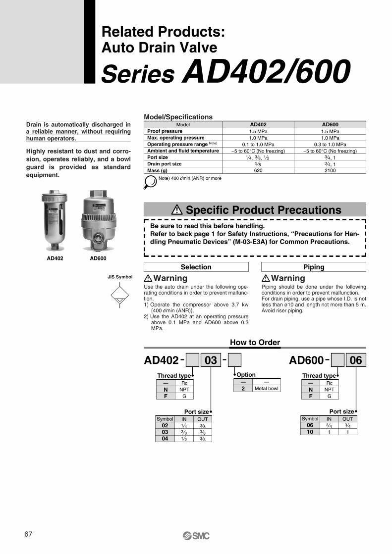
Drain is automatically discharged in a reliable manner, without requiring human operators.
Highly resistant to dust and corro- sion, operates reliably, and a bowl guard is provided as standard equipment.
Selection
Use the auto drain under the following ope-rating conditions in order to prevent malfunc-tion.1) Operate the compressor above 3.7 kw
{400 l/min (ANR)}.2) Use the AD402 at an operating pressure
above 0.1 MPa and AD600 above 0.3 MPa.
WarningPiping
Piping should be done under the following conditions in order to prevent malfunction.For drain piping, use a pipe whose I.D. is not less than ø10 and length not more than 5 m. Avoid riser piping.
Warning
Proof pressureMax. operating pressureOperating pressure range Note)
Ambient and fluid temperaturePort sizeDrain port sizeMass (g)
Model1.5 MPa1.0 MPa
0.1 to 1.0 MPa
620
–5 to 60°C (No freezing)
1.5 MPaAD402 AD600
Note) 400 l/min (ANR) or more
1 4, 3 8,3 8
1 2
1.0 MPa0.3 to 1.0 MPa
2100
–5 to 60°C (No freezing)3 4, 13 4, 1
Model/Specifications
AD402 AD600
JIS Symbol
AD402
OUTINSymbol
0403
Port size
3 8 3 8
02 1 4 3 8
1 2 3 8
RcNPT
G
—NF
Thread type
AD600
OUTINSymbol
10
Port size
06 3 4 3 4
1 1
—Metal bowl2
—Option
03 06
How to Order
RcNPT
G
—NF
Thread type
Related Products:Auto Drain Valve
Series AD402/600
Specific Product PrecautionsBe sure to read this before handling.Refer to back page 1 for Safety Instructions, “Precautions for Han-dling Pneumatic Devices” (M-03-E3A) for Common Precautions.
67
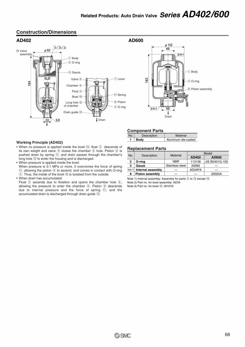
q Body
w O-ring
e Gauze
Valve o u Lever
q Body
w O-ring
i Piston assembly
!1 Spring
i Piston
r O-ring
Chamber y
Float t
Bowl !0
Long hole !2of chamber
Drain guide !3
DrainDrain
Construction/Dimensions
AD402 AD600
Component PartsNo.1
DescriptionBody
MaterialAluminum die-casted
Replacement Parts
No.
2
DescriptionModel
11313620062
AD34PA—
AD402JIS B2401G-100
——
20025A
AD600Material
NBRStainless steel
——
O-ring3
Note 1)
8
GauzeInternal assemblyPiston assembly
Note 1) Internal assembly: Assembly for parts r to !2 except !0.Note 2) Part no. for bowl assembly: AD34Note 3) Part no. for bowl !0: 201016
Working Principle (AD402)• When no pressure is applied inside the bowl !0, float t descends of
its own weight and valve o closes the chamber y hole. Piston i is pushed down by spring !1, and drain passes through the chamber’s long hole !2 to enter the housing and is discharged.
• When pressure is applied inside the bowl:When pressure is 0.1 MPa or more, it overcomes the force of spring !1, allowing the piston i to ascend, and comes in contact with O-ring r. Thus, the inside of the bowl !0 is isolated from the outside.
• When drain has accumulated:Float t ascends due to flotation and opens the chamber hole y, allowing the pressure to enter the chamber y. Piston i descends due to internal pressure and the force of spring !1, and the accumulated drain is discharged through drain guide !3.
Related Products: Auto Drain Valve Series AD402/600
!4 Valveassembly
68
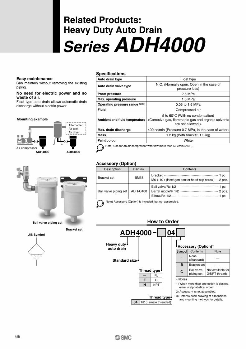
Related Products: Heavy Duty Auto Drain
Series ADH4000
ADH4000
Standard size
Heavy dutyauto drain
04JIS Symbol
Bracket set
Ball valve piping set
Mounting example
Air compressorADH4000 ADH4000
AftercoolerAir tankAir dryer
Specifications
Note) Use for an air compressor with flow more than 50 l/min (ANR).
Float type
N.O. (Normally open: Open in the case ofpressure loss)
2.5 MPa
1.6 MPa
0.05 to 1.6 MPa
Compressed air
400 cc/min (Pressure 0.7 MPa, in the case of water)
1.2 kg (With bracket: 1.3 kg)
White
Auto drain type
Auto drain valve type
Max. drain discharge
Mass
Paint colour
Proof pressure
Max. operating pressure
Operating pressure range Note)
Fluid
Ambient and fluid temperature5 to 60°C (With no condensation)
<Corrosive gas, flammable gas and organic solventsare not allowed.>
Accessory (Option)Description
Bracket set
Ball valve piping set
Part no.
BM58
ADH-C400
Contents
Bracket ··························································· 1 pc.M6 x 10 l (Hexagon socket head cap screw) ··· 2 pcs.
Ball valve/Rc 1/2 ············································· 1 pc.Barrel nipple/R 1/2 ·········································· 2 pcs.Elbow/Rc 1/2··················································· 1 pc.
Note) Accessory (Option) is included, but not assembled.
How to Order
Thread type—
FN
Rc
G
NPT
Thread type04 1/2 (Female threaded)
Easy maintenanceCan maintain without removing the existing piping.
No need for electric power and no waste of air.Float type auto drain allows automatic drain discharge without electric power.
∗ Notes1) When more than one option is desired,
enter in alphabetical order.
2) Accessory is not assembled.
3) Refer to each drawing of dimensions and mounting methods for details.
Accessory (Option)∗
—
B
C
None(Standard)
Symbol Contents
—
—
Note
Ball valve piping set
Not available forG/NPT threads.
Bracket set
69
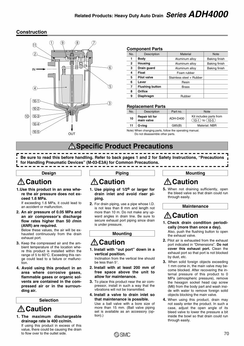
q o i
t
y
e
!1
w
r
10-1
10-2
10-3
10-4
10-5
!0
OUT
IN
u
Construction
No. Description
Body
Housing
Drain guard
Float
Pilot valve
Lever
Flushing button
Orifice
Diaphragm
Component Parts
1
2
3
4
5
6
7
8
9
Material
Aluminum alloy
Aluminum alloy
Aluminum alloy
Foam rubber
Stainless steel + Rubber
Resin
Brass
Rubber
Note
Baking finish
Baking finish
Baking finish
1. Use this product in an area whe-re the air pressure does not ex-ceed 1.6 MPa.If exceeding 1.6 MPa, it could lead to an accident or malfunction.
2. An air pressure of 0.05 MPa and an air compressor’s discharge flow rates higher than 50 l/min (ANR) are required.Below these values, the air will be ex-hausted continuously from the drain exhaust port.
3. Keep the compressed air and the am-bient temperature of the location whe-re this product is installed within the range of 5 to 60°C. Exceeding this ran-ge could lead to a failure or malfunc-tion.
4. Avoid using this product in an area where corrosive gases, flammable gases or organic sol-vents are contained in the com-pressed air or in the surroun-ding air.
Caution
1. The maximum dischargeable drainage rate is 400 cc/min.If using this product in excess of this value, there could be causing the drain to flow over to the outlet side.
Caution
1. Use piping of 1/2B or larger for drain inlet and avoid riser pi-ping.
2. For drain piping, use a pipe whose I.D. is not less than 8 mm and length not more than 10 m. Do not make any up-ward angles in drain line. Be sure to secure exhaust port piping since drain is under pressure.
Caution
1. Check drain condition periodi-cally (more than once a day).Also, push the flushing button to open the exhaust valve.
2. Pilot air is exhausted from the exhaust port indicated in “Dimensions”. Do not cover this exhaust port. Clean the exhaust port so that port is not blocked by dust, etc.
3. When solid foreign objects exceeding 1 mm come in, the main valve may be-come blocked. After recovering the in-ternal pressure of this product to 0 MPa (atmospheric pressure), remove the hexagon socket head cap screw (M6) from the body part and wash insi-de with water to remove foreign solid objects blocking the main valve.
4. When using this product, drain may not easily enter the product. In such a case, adjust the open angle of its bleed valve to lower the pressure a bit inside the bowl so that drain could run through easily.
Caution
Design
Selection
Piping
Maintenance
Specific Product Precautions
1. Install with “out port” down in a vertical position.Inclination from the vertical line should be less than 5°.
2. Install with at least 200 mm of free space above the unit to allow for maintenance.
3. To place this product near the air com-pressor, install in such a way that the vibrations will not be transmitted.
4. Install a valve to drain inlet so that maintenance is possible.Use a ball valve with a bore size of more than 15 mm. (Ball valve piping set is available as an accessory (op-tion).)
CautionMounting
5. When not draining sufficiently, open the bleed valve so that drain could run through easily.
CautionMounting
No. Description
Repair kit for main valve
O-ring
Replacement Parts
10
11
Part no.
ADH-D400
G85(B)
Note
Material: NBR
Note) When changing parts, follow the operating manual.Do not disassemble other parts.
Kit includes parts fromto 10-510-1
Be sure to read this before handling. Refer to back pages 1 and 2 for Safety Instructions, “Precautions for Handling Pneumatic Devices” (M-03-E3A) for Common Precautions.
Related Products: Heavy Duty Auto Drain Series ADH4000
70
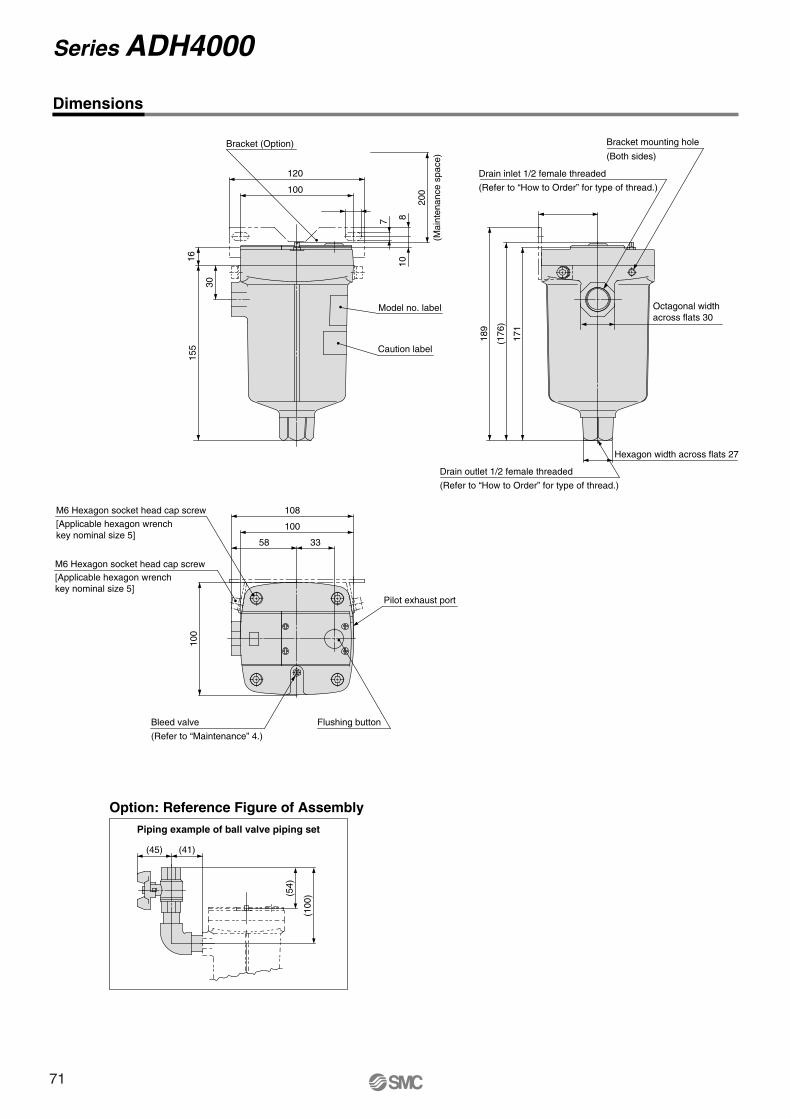
Option: Reference Figure of AssemblyPiping example of ball valve piping set
(54)
(45) (41)
(100
)
108
100
58 33
M6 Hexagon socket head cap screw
[Applicable hexagon wrenchkey nominal size 5]
M6 Hexagon socket head cap screw[Applicable hexagon wrenchkey nominal size 5]
100
Flushing buttonBleed valve
(Refer to “Maintenance” 4.)
Pilot exhaust port
Bracket (Option)
120
100
200
87
10
30
1615
5
Model no. label
Caution label
(Mai
nten
ance
spa
ce)
Bracket mounting hole
(Both sides)
Drain inlet 1/2 female threaded
(Refer to “How to Order” for type of thread.)
171
(176
)
189
Octagonal width across flats 30
Hexagon width across flats 27
Drain outlet 1/2 female threaded
(Refer to “How to Order” for type of thread.)
Dimensions
Series ADH4000
71
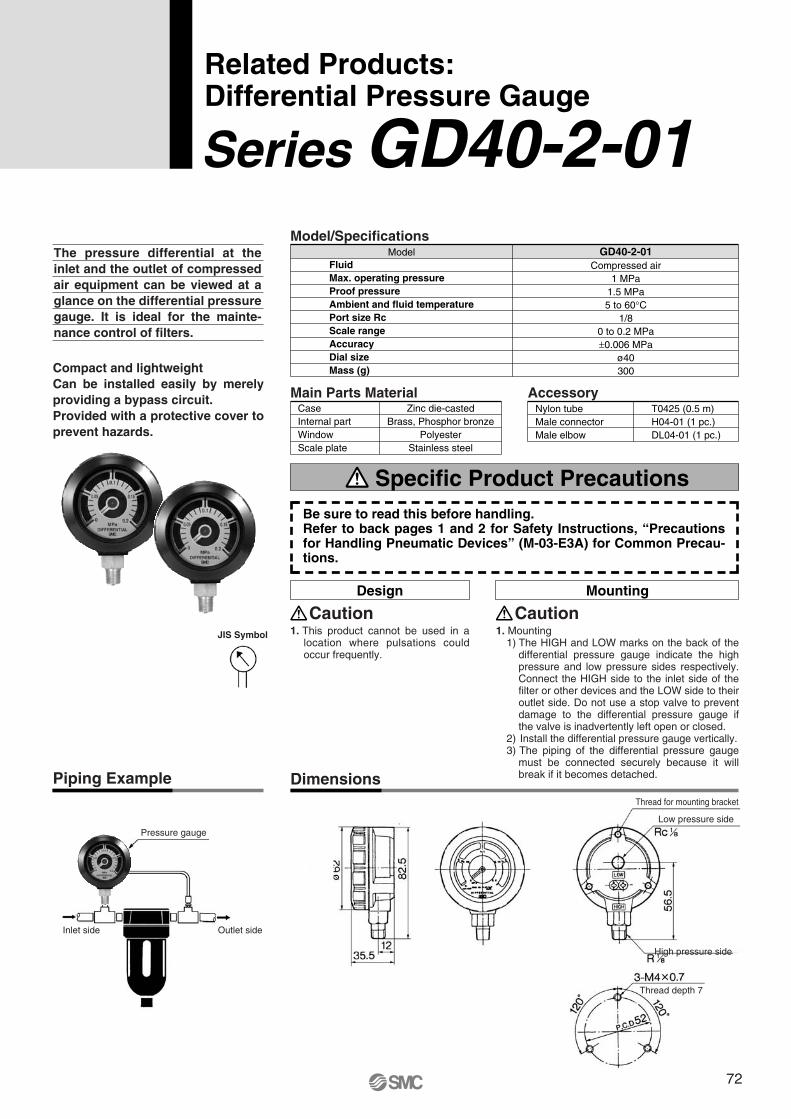
Pressure gauge
Inlet side Outlet side
Thread for mounting bracket
Low pressure side
High pressure side
Thread depth 7
The pressure differential at the inlet and the outlet of compressed air equipment can be viewed at a glance on the differential pressure gauge. It is ideal for the mainte-nance control of filters.
Compact and lightweightCan be installed easily by merely providing a bypass circuit.Provided with a protective cover to prevent hazards.
FluidMax. operating pressureProof pressureAmbient and fluid temperaturePort size RcScale rangeAccuracyDial sizeMass (g)
ModelCompressed air
1 MPa1.5 MPa5 to 60°C
1/80 to 0.2 MPa±0.006 MPa
ø40300
GD40-2-01Model/Specifications
CaseInternal partWindowScale plate
Zinc die-castedBrass, Phosphor bronze
PolyesterStainless steel
Main Parts MaterialNylon tubeMale connectorMale elbow
T0425 (0.5 m)H04-01 (1 pc.)DL04-01 (1 pc.)
Accessory
Related Products: Differential Pressure Gauge
Series GD40-2-01
1. This product cannot be used in a location where pulsations could occur frequently.
CautionDesign Mounting
1. Mounting1) The HIGH and LOW marks on the back of the
differential pressure gauge indicate the high pressure and low pressure sides respectively. Connect the HIGH side to the inlet side of the filter or other devices and the LOW side to their outlet side. Do not use a stop valve to prevent damage to the differential pressure gauge if the valve is inadvertently left open or closed.
2) Install the differential pressure gauge vertically.3) The piping of the differential pressure gauge
must be connected securely because it will break if it becomes detached.
Caution
Piping Example Dimensions
JIS Symbol
Be sure to read this before handling.Refer to back pages 1 and 2 for Safety Instructions, “Precautions for Handling Pneumatic Devices” (M-03-E3A) for Common Precau-tions.
Specific Product Precautions
72
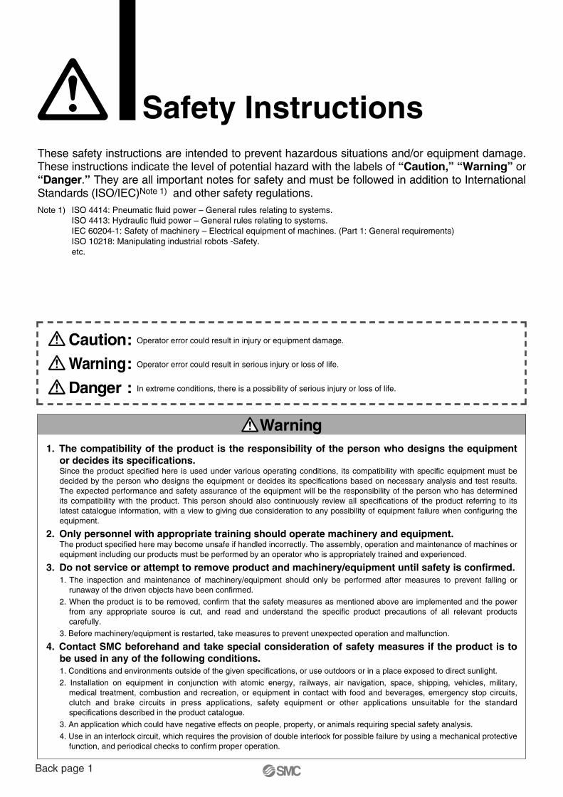
Safety InstructionsThese safety instructions are intended to prevent hazardous situations and/or equipment damage. These instructions indicate the level of potential hazard with the labels of “Caution,” “Warning” or “Danger.” They are all important notes for safety and must be followed in addition to International Standards (ISO/IEC)Note 1) and other safety regulations.Note 1) ISO 4414: Pneumatic fluid power – General rules relating to systems.
ISO 4413: Hydraulic fluid power – General rules relating to systems.IEC 60204-1: Safety of machinery – Electrical equipment of machines. (Part 1: General requirements)ISO 10218: Manipulating industrial robots -Safety.etc.
1. The compatibility of the product is the responsibility of the person who designs the equipment or decides its specifications. Since the product specified here is used under various operating conditions, its compatibility with specific equipment must be decided by the person who designs the equipment or decides its specifications based on necessary analysis and test results. The expected performance and safety assurance of the equipment will be the responsibility of the person who has determined its compatibility with the product. This person should also continuously review all specifications of the product referring to its latest catalogue information, with a view to giving due consideration to any possibility of equipment failure when configuring the equipment.
2. Only personnel with appropriate training should operate machinery and equipment.The product specified here may become unsafe if handled incorrectly. The assembly, operation and maintenance of machines or equipment including our products must be performed by an operator who is appropriately trained and experienced.
3. Do not service or attempt to remove product and machinery/equipment until safety is confirmed.1. The inspection and maintenance of machinery/equipment should only be performed after measures to prevent falling or
runaway of the driven objects have been confirmed.
2. When the product is to be removed, confirm that the safety measures as mentioned above are implemented and the power from any appropriate source is cut, and read and understand the specific product precautions of all relevant products carefully.
3. Before machinery/equipment is restarted, take measures to prevent unexpected operation and malfunction.
4. Contact SMC beforehand and take special consideration of safety measures if the product is to be used in any of the following conditions. 1. Conditions and environments outside of the given specifications, or use outdoors or in a place exposed to direct sunlight.
2. Installation on equipment in conjunction with atomic energy, railways, air navigation, space, shipping, vehicles, military, medical treatment, combustion and recreation, or equipment in contact with food and beverages, emergency stop circuits, clutch and brake circuits in press applications, safety equipment or other applications unsuitable for the standard specifications described in the product catalogue.
3. An application which could have negative effects on people, property, or animals requiring special safety analysis.
4. Use in an interlock circuit, which requires the provision of double interlock for possible failure by using a mechanical protective function, and periodical checks to confirm proper operation.
Warning
Caution: Operator error could result in injury or equipment damage.
Danger : In extreme conditions, there is a possibility of serious injury or loss of life.
Warning: Operator error could result in serious injury or loss of life.
Back page 1
Safety Instructions
Limited Warranty and Disclaimer/Compliance Requirements The product used is subject to the following “Limited Warranty and Disclaimer” and “Compliance Requirements”. Read and accept them before using the product.
The product is provided for use in manufacturing industries.The product herein described is basically provided for peaceful use in manufacturing industries. If considering using the product in other industries, consult SMC beforehand and exchange specifications or a contract if necessary. If anything is unclear, contact your nearest sales branch.
Caution
Limited Warranty and Disclaimer
1. The warranty period of the product is 1 year in service or 1.5 years after the product is delive-red.Note 2)
The product may also have specified durability, running distance or replacement parts. Please consult your nearest sales branch.
2. For any failure or damage reported within the warranty period, which is clearly SMC's responsi-bility, a replacement product or necessary parts will be provided. This limited warranty applies only to SMC product independently, and not to any other damage incurred due to failure of the product.
3. Before using SMC products, please read and understand the warranty terms and disclaimers no-ted in the specified catalogue for the particular products.Note 2) Vacuum pads are excluded from this 1 year warranty.
A vacuum pad is a consumable part, so it is warranted for a year after it is delivered. Also, even within the warranty period, the wear of a product due to the use of the vacuum pad or failure due to the deterioration of rubber material are not covered by the limited warranty.
Compliance RequirementsWhen the product is exported, strictly follow the laws required by the Ministry of Economy, Trade and Industry (Foreign Exchange and Foreign Trade Control Law).
Back page 2
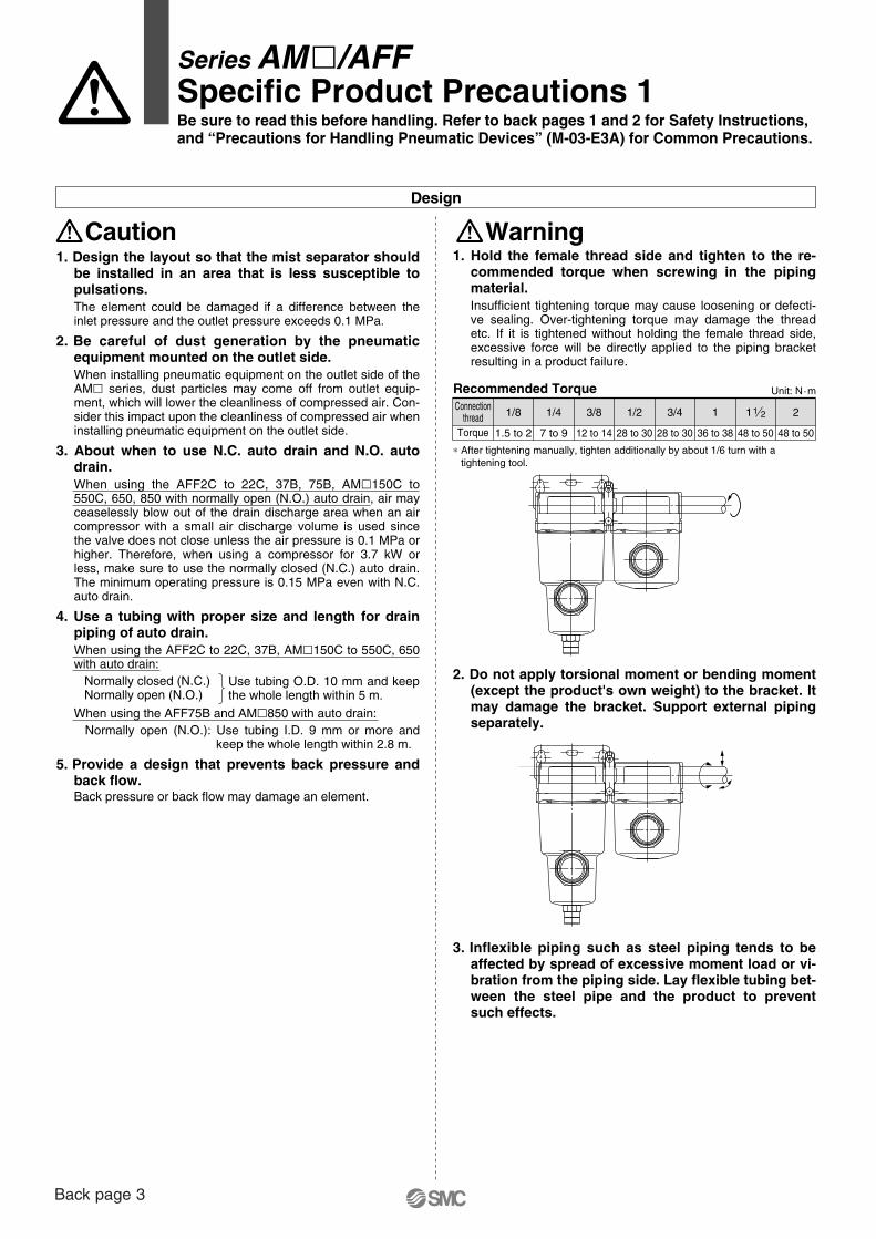
Design
Caution
Series AM�/AFFSpecific Product Precautions 1Be sure to read this before handling. Refer to back pages 1 and 2 for Safety Instructions,and “Precautions for Handling Pneumatic Devices” (M-03-E3A) for Common Precautions.
Warning1. Hold the female thread side and tighten to the re-
commended torque when screwing in the piping material.Insufficient tightening torque may cause loosening or defecti-ve sealing. Over-tightening torque may damage the thread etc. If it is tightened without holding the female thread side, excessive force will be directly applied to the piping bracket resulting in a product failure.
2. Do not apply torsional moment or bending moment (except the product's own weight) to the bracket. It may damage the bracket. Support external piping separately.
3. Inflexible piping such as steel piping tends to beaffected by spread of excessive moment load or vi-bration from the piping side. Lay flexible tubing bet-ween the steel pipe and the product to prevent such effects.
1. Design the layout so that the mist separator should be installed in an area that is less susceptible to pulsations.The element could be damaged if a difference between the inlet pressure and the outlet pressure exceeds 0.1 MPa.
2. Be careful of dust generation by the pneumatic equipment mounted on the outlet side. When installing pneumatic equipment on the outlet side of the AM� series, dust particles may come off from outlet equip-ment, which will lower the cleanliness of compressed air. Con-sider this impact upon the cleanliness of compressed air when installing pneumatic equipment on the outlet side.
3. About when to use N.C. auto drain and N.O. auto drain. When using the AFF2C to 22C, 37B, 75B, AM�150C to 550C, 650, 850 with normally open (N.O.) auto drain, air may ceaselessly blow out of the drain discharge area when an air compressor with a small air discharge volume is used since the valve does not close unless the air pressure is 0.1 MPa or higher. Therefore, when using a compressor for 3.7 kW or less, make sure to use the normally closed (N.C.) auto drain. The minimum operating pressure is 0.15 MPa even with N.C. auto drain.
4. Use a tubing with proper size and length for drain piping of auto drain.When using the AFF2C to 22C, 37B, AM�150C to 550C, 650 with auto drain: Normally closed (N.C.) Normally open (N.O.)
When using the AFF75B and AM�850 with auto drain: Normally open (N.O.): Use tubing I.D. 9 mm or more and
keep the whole length within 2.8 m.
5. Provide a design that prevents back pressure and back flow.Back pressure or back flow may damage an element.
Use tubing O.D. 10 mm and keep the whole length within 5 m.
Connectionthread
Torque
1/8 1/4 3/8 1/2 3/4 1 1 2
1.5 to 2 7 to 9 12 to 14 28 to 30 28 to 30 36 to 38 48 to 50 48 to 50
∗ After tightening manually, tighten additionally by about 1/6 turn with atightening tool.
Unit: N·mRecommended Torque
1 2
Back page 3
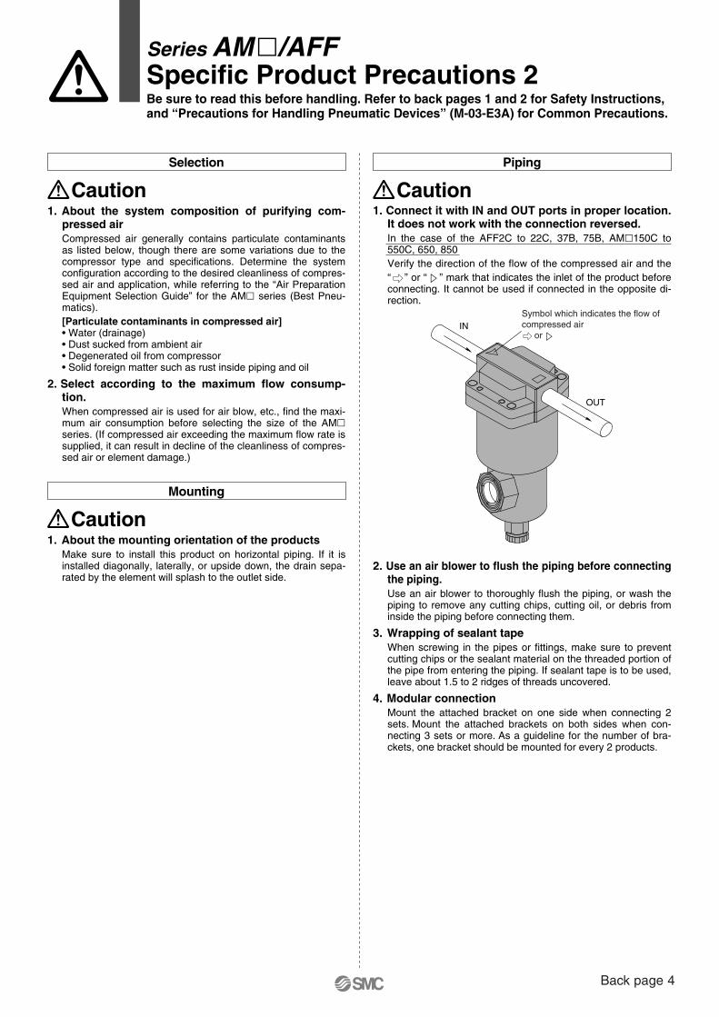
IN
OUT
Symbol which indicates the flow ofcompressed air or
Caution1. About the mounting orientation of the products
Make sure to install this product on horizontal piping. If it is installed diagonally, laterally, or upside down, the drain sepa-rated by the element will splash to the outlet side.
Mounting
Selection
Caution1. About the system composition of purifying com-
pressed airCompressed air generally contains particulate contaminants as listed below, though there are some variations due to the compressor type and specifications. Determine the system configuration according to the desired cleanliness of compres-sed air and application, while referring to the “Air Preparation Equipment Selection Guide” for the AM� series (Best Pneu-matics).[Particulate contaminants in compressed air]• Water (drainage)• Dust sucked from ambient air• Degenerated oil from compressor• Solid foreign matter such as rust inside piping and oil
2. Select according to the maximum flow consump-tion.When compressed air is used for air blow, etc., find the maxi-mum air consumption before selecting the size of the AM� series. (If compressed air exceeding the maximum flow rate is supplied, it can result in decline of the cleanliness of compres-sed air or element damage.)
CautionPiping
2. Use an air blower to flush the piping before connecting the piping. Use an air blower to thoroughly flush the piping, or wash the piping to remove any cutting chips, cutting oil, or debris from inside the piping before connecting them.
3. Wrapping of sealant tapeWhen screwing in the pipes or fittings, make sure to prevent cutting chips or the sealant material on the threaded portion of the pipe from entering the piping. If sealant tape is to be used, leave about 1.5 to 2 ridges of threads uncovered.
4. Modular connectionMount the attached bracket on one side when connecting 2 sets. Mount the attached brackets on both sides when con-necting 3 sets or more. As a guideline for the number of bra-ckets, one bracket should be mounted for every 2 products.
1. Connect it with IN and OUT ports in proper location. It does not work with the connection reversed.In the case of the AFF2C to 22C, 37B, 75B, AM�150C to 550C, 650, 850Verify the direction of the flow of the compressed air and the“ ” or “ ” mark that indicates the inlet of the product before connecting. It cannot be used if connected in the opposite di-rection.
Series AM�/AFFSpecific Product Precautions 2Be sure to read this before handling. Refer to back pages 1 and 2 for Safety Instructions,and “Precautions for Handling Pneumatic Devices” (M-03-E3A) for Common Precautions.
Back page 4
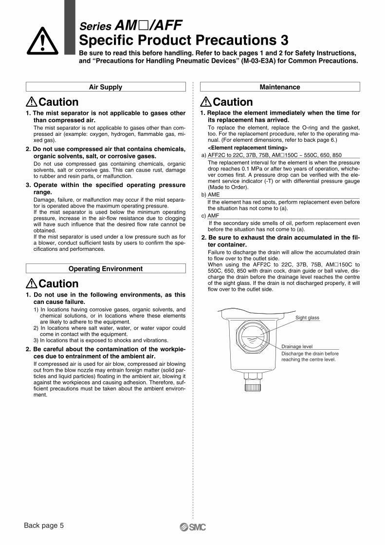
Sight glass
Drainage level
Discharge the drain before reaching the centre level.
Air Supply
Caution1. The mist separator is not applicable to gases other
than compressed air.The mist separator is not applicable to gases other than com-pressed air (example: oxygen, hydrogen, flammable gas, mi-xed gas).
2. Do not use compressed air that contains chemicals, organic solvents, salt, or corrosive gases.Do not use compressed gas containing chemicals, organic solvents, salt or corrosive gas. This can cause rust, damage to rubber and resin parts, or malfunction.
3. Operate within the specified operating pressure range.Damage, failure, or malfunction may occur if the mist separa-tor is operated above the maximum operating pressure.If the mist separator is used below the minimum operating pressure, increase in the air-flow resistance due to clogging will have such influence that the desired flow rate cannot be obtained.If the mist separator is used under a low pressure such as for a blower, conduct sufficient tests by users to confirm the spe-cifications and performances.
Operating Environment
Caution1. Do not use in the following environments, as this
can cause failure.1) In locations having corrosive gases, organic solvents, and
chemical solutions, or in locations where these elements are likely to adhere to the equipment.
2) In locations where salt water, water, or water vapor could come in contact with the equipment.
3) In locations that is exposed to shocks and vibrations.
2. Be careful about the contamination of the workpie-ces due to entrainment of the ambient air.If compressed air is used for air blow, compressed air blowing out from the blow nozzle may entrain foreign matter (solid par-ticles and liquid particles) floating in the ambient air, blowing it against the workpieces and causing adhesion. Therefore, suf-ficient precautions must be taken about the ambient environ-ment.
Maintenance
Caution1. Replace the element immediately when the time for
its replacement has arrived.To replace the element, replace the O-ring and the gasket, too. For the replacement procedure, refer to the operating ma-nual. (For element dimensions, refer to back page 6.)<Element replacement timing>
a) AFF2C to 22C, 37B, 75B, AM�150C ~ 550C, 650, 850The replacement interval for the element is when the pressure drop reaches 0.1 MPa or after two years of operation, whiche-ver comes first. A pressure drop can be verified with the ele-ment service indicator (-T) or with differential pressure gauge (Made to Order).
b) AMEIf the element has red spots, perform replacement even before the situation has not come to (a).
c) AMFIf the secondary side smells of oil, perform replacement even before the situation has not come to (a).
2. Be sure to exhaust the drain accumulated in the fil-ter container.Failure to discharge the drain will allow the accumulated drain to flow over to the outlet side.When using the AFF2C to 22C, 37B, 75B, AM�150C to 550C, 650, 850 with drain cock, drain guide or ball valve, dis-charge the drain before the drainage level reaches the centre of the sight glass. If the drain is not discharged properly, it will flow over to the outlet side.
Series AM�/AFFSpecific Product Precautions 3Be sure to read this before handling. Refer to back pages 1 and 2 for Safety Instructions,and “Precautions for Handling Pneumatic Devices” (M-03-E3A) for Common Precautions.
Back page 5
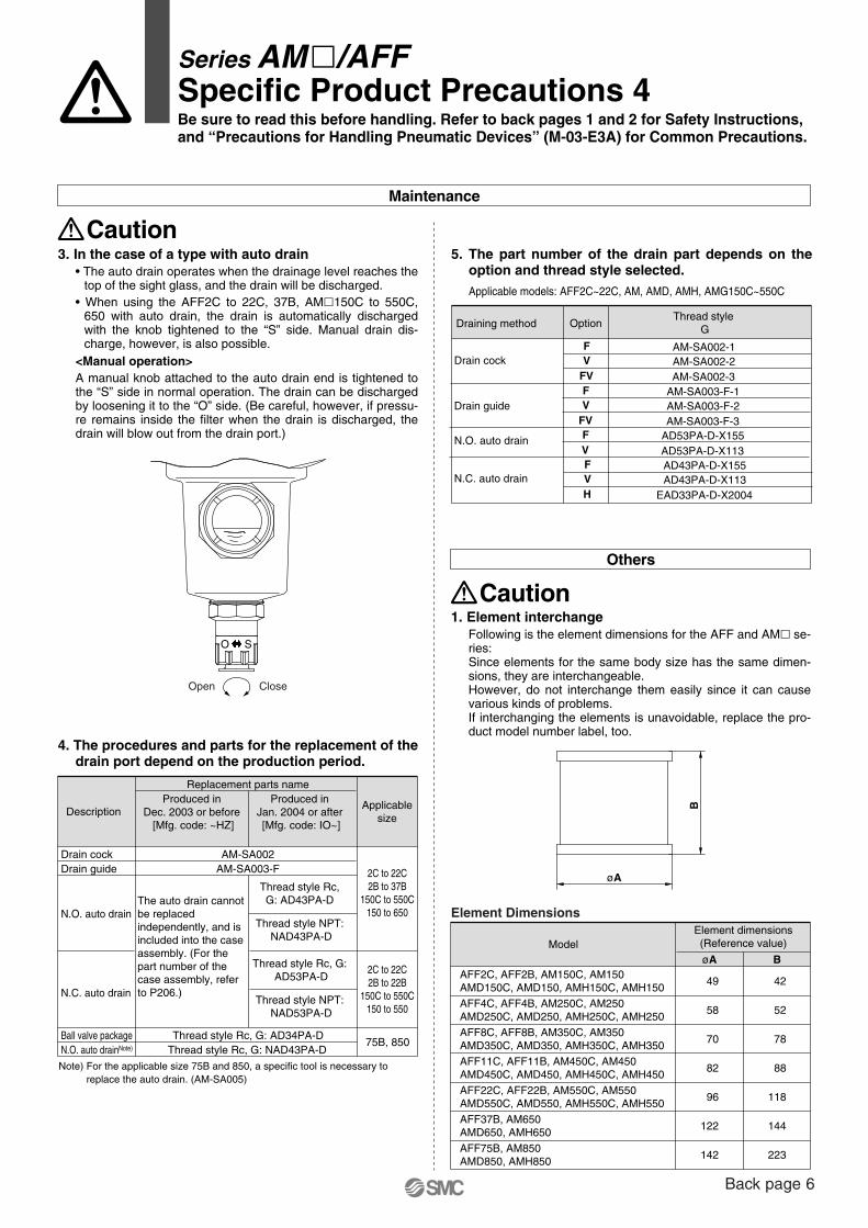
Open Close
O S
øA
B
Others
Caution1. Element interchange
Following is the element dimensions for the AFF and AM� se-ries:Since elements for the same body size has the same dimen-sions, they are interchangeable.However, do not interchange them easily since it can cause various kinds of problems.If interchanging the elements is unavoidable, replace the pro-duct model number label, too.
Element Dimensions
ModelElement dimensions(Reference value)
øA BAFF2C, AFF2B, AM150C, AM150AMD150C, AMD150, AMH150C, AMH150
AFF4C, AFF4B, AM250C, AM250AMD250C, AMD250, AMH250C, AMH250
AFF8C, AFF8B, AM350C, AM350AMD350C, AMD350, AMH350C, AMH350
AFF11C, AFF11B, AM450C, AM450AMD450C, AMD450, AMH450C, AMH450
AFF22C, AFF22B, AM550C, AM550AMD550C, AMD550, AMH550C, AMH550
AFF37B, AM650AMD650, AMH650
49
58
70
82
96
122
142
42
52
78
88
118
144
223AFF75B, AM850AMD850, AMH850
Maintenance
Caution3. In the case of a type with auto drain
• The auto drain operates when the drainage level reaches the top of the sight glass, and the drain will be discharged.
• When using the AFF2C to 22C, 37B, AM�150C to 550C, 650 with auto drain, the drain is automatically discharged with the knob tightened to the “S” side. Manual drain dis-charge, however, is also possible.
<Manual operation>A manual knob attached to the auto drain end is tightened to the “S” side in normal operation. The drain can be discharged by loosening it to the “O” side. (Be careful, however, if pressu-re remains inside the filter when the drain is discharged, the drain will blow out from the drain port.)
4. The procedures and parts for the replacement of the drain port depend on the production period.
Description
AM-SA003-F
Thread style Rc, G: AD34PA-DThread style Rc, G: NAD43PA-D
Thread style Rc,G: AD43PA-D
Thread style NPT:NAD43PA-D
Thread style Rc, G:AD53PA-D
Thread style NPT:NAD53PA-D
AM-SA002
Replacement parts nameProduced in
Dec. 2003 or before[Mfg. code: ~HZ]
Produced inJan. 2004 or after[Mfg. code: IO~]
Applicablesize
2C to 22C2B to 37B
150C to 550C150 to 650
2C to 22C2B to 22B
150C to 550C150 to 550
75B, 850
Drain guideDrain cock
Ball valve packageN.O. auto drainNote)
N.O. auto drain
N.C. auto drain
The auto drain cannot be replaced independently, and is included into the case assembly. (For the part number of the case assembly, refer to P206.)
Note) For the applicable size 75B and 850, a specific tool is necessary to replace the auto drain. (AM-SA005)
Series AM�/AFFSpecific Product Precautions 4Be sure to read this before handling. Refer to back pages 1 and 2 for Safety Instructions,and “Precautions for Handling Pneumatic Devices” (M-03-E3A) for Common Precautions.
5. The part number of the drain part depends on the option and thread style selected. Applicable models: AFF2C~22C, AM, AMD, AMH, AMG150C~550C
Draining method
AM-SA002-2AM-SA002-1
Thread style GOption
Drain guide
Drain cock
N.O. auto drain
N.C. auto drain
AM-SA002-3
VF
FV
AM-SA003-F-2AM-SA003-F-1
AM-SA003-F-3
VF
FVAD53PA-D-X155AD53PA-D-X113
FV
AD43PA-D-X113AD43PA-D-X155
EAD33PA-D-X2004
VF
H
Back page 6
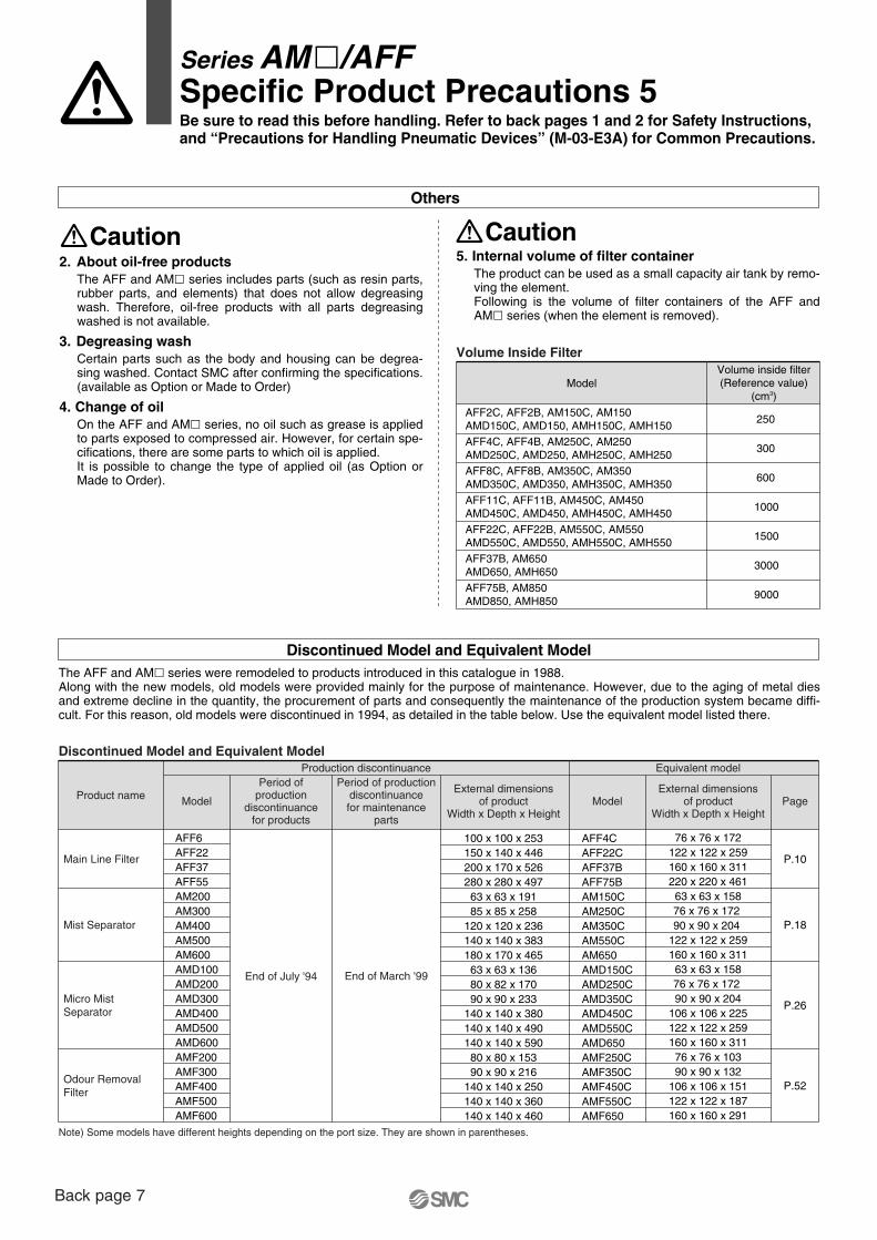
Discontinued Model and Equivalent ModelThe AFF and AM� series were remodeled to products introduced in this catalogue in 1988.Along with the new models, old models were provided mainly for the purpose of maintenance. However, due to the aging of metal dies and extreme decline in the quantity, the procurement of parts and consequently the maintenance of the production system became diffi-cult. For this reason, old models were discontinued in 1994, as detailed in the table below. Use the equivalent model listed there.
Discontinued Model and Equivalent Model
Note) Some models have different heights depending on the port size. They are shown in parentheses.
Product name Model Model
AFF4CAFF22CAFF37BAFF75BAM150CAM250CAM350CAM550CAM650AMD150CAMD250CAMD350CAMD450CAMD550CAMD650AMF250CAMF350CAMF450CAMF550CAMF650
Period ofproduction
discontinuancefor products
End of July '94
Period of productiondiscontinuancefor maintenance
parts
End of March '99
External dimensionsof product
Width x Depth x Height
100 x 100 x 253150 x 140 x 446200 x 170 x 526280 x 280 x 497
63 x 63 x 19185 x 85 x 258
120 x 120 x 236140 x 140 x 383180 x 170 x 465
63 x 63 x 13680 x 82 x 17090 x 90 x 233
140 x 140 x 380140 x 140 x 490140 x 140 x 590
80 x 80 x 15390 x 90 x 216
140 x 140 x 250140 x 140 x 360140 x 140 x 460
External dimensionsof product
Width x Depth x Height
76 x 76 x 172122 x 122 x 259160 x 160 x 311220 x 220 x 461
63 x 63 x 15876 x 76 x 172 90 x 90 x 204
122 x 122 x 259160 x 160 x 311
63 x 63 x 15876 x 76 x 172 90 x 90 x 204
106 x 106 x 225122 x 122 x 259160 x 160 x 311
76 x 76 x 10390 x 90 x 132
106 x 106 x 151122 x 122 x 187160 x 160 x 291
P.10
P.18
P.26
P.52
Page
Production discontinuance Equivalent model
Main Line Filter
AFF6AFF22AFF37AFF55AM200AM300AM400AM500AM600AMD100AMD200AMD300AMD400AMD500AMD600AMF200AMF300AMF400AMF500AMF600
Mist Separator
Micro Mist Separator
Odour Removal Filter
Others
CautionCaution5. Internal volume of filter container
The product can be used as a small capacity air tank by remo-ving the element.Following is the volume of filter containers of the AFF and AM� series (when the element is removed).
Volume Inside Filter
Model
250
Volume inside filter(Reference value)
(cm3)
AFF2C, AFF2B, AM150C, AM150AMD150C, AMD150, AMH150C, AMH150
300AFF4C, AFF4B, AM250C, AM250AMD250C, AMD250, AMH250C, AMH250
600AFF8C, AFF8B, AM350C, AM350AMD350C, AMD350, AMH350C, AMH350
1000AFF11C, AFF11B, AM450C, AM450AMD450C, AMD450, AMH450C, AMH450
1500AFF22C, AFF22B, AM550C, AM550AMD550C, AMD550, AMH550C, AMH550
3000AFF37B, AM650AMD650, AMH650
9000AFF75B, AM850AMD850, AMH850
Series AM�/AFFSpecific Product Precautions 5Be sure to read this before handling. Refer to back pages 1 and 2 for Safety Instructions,and “Precautions for Handling Pneumatic Devices” (M-03-E3A) for Common Precautions.
2. About oil-free productsThe AFF and AM� series includes parts (such as resin parts, rubber parts, and elements) that does not allow degreasing wash. Therefore, oil-free products with all parts degreasing washed is not available.
3. Degreasing washCertain parts such as the body and housing can be degrea-sing washed. Contact SMC after confirming the specifications. (available as Option or Made to Order)
4. Change of oilOn the AFF and AM� series, no oil such as grease is applied to parts exposed to compressed air. However, for certain spe-cifications, there are some parts to which oil is applied.It is possible to change the type of applied oil (as Option or Made to Order).
Back page 7
SMC CORPORATION Akihabara UDX 15F, 4-14-1, Sotokanda, Chiyoda-ku, Tokyo 101-0021, JAPAN Phone: 03-5207-8249 FAX: 03-5298-5362Specifications are subject to change without prior notice
and any obligation on the part of the manufacturer.
ARGENTINA, AUSTRALIA, BOLIVIA, BRASIL, CANADA, CHILE,CHINA, HONG KONG, INDIA, INDONESIA, MALAYSIA, MEXICO,NEW ZEALAND, PHILIPPINES, SINGAPORE, SOUTH KOREA,
TAIWAN, THAILAND, USA, VENEZUELA
OTHER SUBSIDIARIES WORLDWIDE:
© DiskArt™ 1988
© DiskArt™ UKSMC Pneumatics (UK) LtdVincent Avenue, Crownhill, Milton Keynes, MK8 0ANPhone: +44 (0)800 1382930 Fax: +44 (0)1908-555064E-mail: [email protected]://www.smcpneumatics.co.uk
AustriaSMC Pneumatik GmbH (Austria).Girakstrasse 8, A-2100 KorneuburgPhone: +43 2262-622800, Fax: +43 2262-62285E-mail: [email protected]://www.smc.at
Czech RepublicSMC Industrial Automation CZ s.r.o.Hudcova 78a, CZ-61200 BrnoPhone: +420 5 414 24611, Fax: +420 5 412 18034E-mail: [email protected]://www.smc.cz
PortugalSMC Sucursal Portugal, S.A.Rua de Engº Ferreira Dias 452, 4100-246 PortoPhone: +351 226 166 570, Fax: +351 226 166 589E-mail: [email protected]://www.smc.eu
BelgiumSMC Pneumatics N.V./S.A.Nijverheidsstraat 20, B-2160 WommelgemPhone: +32 (0)3-355-1464, Fax: +32 (0)3-355-1466E-mail: [email protected]://www.smcpneumatics.be
LithuaniaSMC Pneumatics Lietuva, UABOslo g.1, LT-04123 VilniusPhone: +370 5 264 81 26, Fax: +370 5 264 81 26
LatviaSMC Pneumatics Latvia SIADzelzavas str. 120g, Riga LV-1021, LATVIAPhone: +371 67817700, Fax: +371 67817701E-mail: [email protected]://www.smclv.lv
SwedenSMC Pneumatics Sweden ABEkhagsvägen 29-31, S-141 71 HuddingePhone: +46 (0)8-603 12 00, Fax: +46 (0)8-603 12 90E-mail: [email protected]://www.smc.nu
FranceSMC Pneumatique, S.A.1, Boulevard de Strasbourg, Parc Gustave EiffelBussy Saint Georges F-77607 Marne La Vallee Cedex 3Phone: +33 (0)1-6476 1000, Fax: +33 (0)1-6476 1010E-mail: [email protected]://www.smc-france.fr
FinlandSMC Pneumatics Finland OyPL72, Tiistinniityntie 4, SF-02231 ESPOOPhone: +358 207 513513, Fax: +358 207 513595E-mail: [email protected]://www.smc.fi
EstoniaSMC Pneumatics Estonia OÜLaki 12, 106 21 TallinnPhone: +372 6510370, Fax: +372 65110371E-mail: [email protected]://www.smcpneumatics.ee
GreeceSMC Hellas EPEAnagenniseos 7-9 - P.C. 14342. N. Philadelphia, AthensPhone: +30-210-2717265, Fax: +30-210-2717766E-mail: [email protected]://www.smchellas.gr
TurkeyEntek Pnömatik San. ve Tic. A*.Perpa Ticaret Merkezi B Blok Kat:11 No: 1625, TR-34386, Okmeydani, IstanbulPhone: +90 (0)212-444-0762, Fax: +90 (0)212-221-1519E-mail: [email protected]://www.entek.com.tr
PolandSMC Industrial Automation Polska Sp.z.o.o.ul. Poloneza 89, PL-02-826 Warszawa, Phone: +48 22 211 9600, Fax: +48 22 211 9617E-mail: [email protected]://www.smc.pl
NetherlandsSMC Pneumatics BVDe Ruyterkade 120, NL-1011 AB AmsterdamPhone: +31 (0)20-5318888, Fax: +31 (0)20-5318880E-mail: [email protected]://www.smcpneumatics.nl
IrelandSMC Pneumatics (Ireland) Ltd.2002 Citywest Business Campus, Naas Road, Saggart, Co. DublinPhone: +353 (0)1-403 9000, Fax: +353 (0)1-464-0500E-mail: [email protected]://www.smcpneumatics.ie
HungarySMC Hungary Ipari Automatizálási Kft.Torbágy út 19, H-2045 TörökbálintPhone: +36 23 511 390, Fax: +36 23 511 391E-mail: [email protected]://www.smc.hu
SwitzerlandSMC Pneumatik AGDorfstrasse 7, CH-8484 WeisslingenPhone: +41 (0)52-396-3131, Fax: +41 (0)52-396-3191E-mail: [email protected]://www.smc.ch
ItalySMC Italia S.p.AVia Garibaldi 62, I-20061 Carugate, (Milano)Phone: +39 (0)2-92711, Fax: +39 (0)2-9271365E-mail: [email protected]://www.smcitalia.it
GermanySMC Pneumatik GmbHBoschring 13-15, D-63329 EgelsbachPhone: +49 (0)6103-4020, Fax: +49 (0)6103-402139E-mail: [email protected]://www.smc-pneumatik.de
SloveniaSMC industrijska Avtomatika d.o.o.Mirnska cesta 7, SI-8210 TrebnjePhone: +386 7 3885412 Fax: +386 7 3885435E-mail: [email protected]://www.smc.si
SlovakiaSMC Priemyselná Automatizáciá, s.r.o.Fatranská 1223, 01301 Teplicka Nad VáhomPhone: +421 41 3213212 - 6 Fax: +421 41 3213210E-mail: [email protected]://www.smc.sk
RomaniaSMC Romania srlStr Frunzei 29, Sector 2, BucharestPhone: +40 213205111, Fax: +40 213261489E-mail: [email protected]://www.smcromania.ro
NorwaySMC Pneumatics Norway A/SVollsveien 13 C, Granfos Næringspark N-1366 LysakerTel: +47 67 12 90 20, Fax: +47 67 12 90 21E-mail: [email protected]://www.smc-norge.no
DenmarkSMC Pneumatik A/SEgeskovvej 1, DK-8700 HorsensPhone: +45 70252900, Fax: +45 70252901E-mail: [email protected]://www.smcdk.com
RussiaSMC Pneumatik LLC.4B Sverdlovskaja nab, St. Petersburg 195009Phone.:+7 812 718 5445, Fax:+7 812 718 5449E-mail: [email protected]://www.smc-pneumatik.ru
SpainSMC España, S.A.Zuazobidea 14, 01015 VitoriaPhone: +34 945-184 100, Fax: +34 945-184 124E-mail: [email protected]://www.smc.eu
http://www.smc.euhttp://www.smcworld.com
EUROPEAN SUBSIDIARIES:
BulgariaSMC Industrial Automation Bulgaria EOODBusiness Park Sofia, Building 8 - 6th floor, BG-1715 SofiaPhone:+359 2 9744492, Fax:+359 2 9744519E-mail: [email protected]://www.smc.bg
CroatiaSMC Industrijska automatika d.o.o.Crnomerec 12, HR-10000 ZAGREBPhone: +385 1 377 66 74, Fax: +385 1 377 66 74E-mail: [email protected]://www.smc.hr
1st printing NS printing NS 00 Printed in Spain