Comprehensive Study of Cryogenic Fluid Dynamics … J (2017...Comprehensive Study of Cryogenic Fluid...
11
Comprehensive Study of Cryogenic Fluid Dynamics of Swirl Injectors at Supercritical Conditions Xingjian Wang ∗ Georgia Institute of Technology, Atlanta, Georgia 30332 Hongfa Huo † General Electric Company, Niskayuna, NY 12309 and Yanxing Wang ‡ and Vigor Yang § Georgia Institute of Technology, Atlanta, Georgia 30332 DOI: 10.2514/1.J055868 A comprehensive study is conducted to enhance the understanding of swirl injector flow dynamics at supercritical conditions. The formulation is based on full-conservation laws and accommodates real-fluid thermodynamics and transport theories over the entire range of fluid states of concern. Liquid oxygen at 120 K is injected into a supercritical oxygen environment at 300–600 K. Detailed three-dimensional flow structures are visualized for the first time in the pressure range of 100–200 atm. A smooth fluid transition from the compressed-liquid to light-gas state occurs, which is in contrast to a distinct interface of phase change at subcritical pressure. Dynamic behaviors of the oscillatory flowfield are explored using the spectral analysis and proper orthogonal decomposition technique. Various underlying mechanisms dictating flow evolution, including shear-layer, helical, centrifugal, and acoustic instabilities, are studied in depth. The hydrodynamic wave motions in the liquid-oxygen film are found to propagate in two different modes: one along the axial direction at the local wave speed; the other in the azimuthal direction and convected downstream at the mean flow velocity. Results show good agreement with the analytical prediction of the overall response transfer function of the swirl injector. The dominant mode of the azimuthal wave is triggered by the natural acoustic oscillation within the injector. Compared with the two-dimensional axisymmetric results, the calculated liquid-oxygen film is thicker and the spreading angle smaller due to the momentum loss and vortical dynamics in the azimuthal direction. I. Introduction S WIRL injectors are widely used in many propulsion and power- generation systems, including airbreathing engines [1,2] and liquid rockets [3]. The swirling motion induces outward spreading of the liquid film and produces a center toroidal recirculation zone downstream of the injector, thereby significantly improving mixing and combustion efficiency. Extensive experimental [4–8] studies have been conducted to examine the flow characteristics of swirl injectors, including spreading angle, liquid film thickness, and discharge coefficient, under various geometric and operating conditions. Kim et al. [9] studied the flow dynamics of liquid swirl injectors, with water as the working fluid. The spreading angle and breakup length of the liquid film issued from the injection exit were measured using direct photography, in the Weber number range of 170–1554 and pressure range of 1–40 bar. As the pressure increased, the spreading angle remained nearly constant until the breakup of the liquid sheet, and then it decreased slightly. The breakup length decreased with the increasing Weber number and pressure due to enhanced aerodynamic force. In addition, the spreading angle increased with increasing Weber numbers. Kenny et al. [10] examined the effect of ambient pressure on water swirl injection using shadowgraphs. The measured film thickness and discharge coefficient increased with increasing pressure from 1 to 48 bar for a given mass flow rate. Chen and Yang [11] confirmed Kenny et al. ’ s results [10] by performing a combined theoretical and numerical analysis. They found that variations of the film thickness and spray angle with pressure were closely related to the modification of the velocity profile in the liquid film near the gas–liquid interface due to the alteration of shear stresses with pressure. A semiempirical model was developed to correlate the distributions of velocity and pressure near the gas–liquid interface, and good agreement with experimental observations was achieved. Cho et al. [12] conducted experimental studies on the surface instability of a swirl injector with cryogenic fluid (liquid nitrogen) at both subcritical and supercritical conditions. Flow images were obtained using high-speed photography. The amplitude of the surface wave of liquid nitrogen was found to be much higher than that in water under the same operating conditions. The flow characteristics changed dramatically when the ambient pressure increased from a subcritical to a supercritical condition. The surface wave immediately downstream of the injector under subcritical conditions disappeared at supercritical pressures. Cho et al. [13] further investigated the dynamic behaviors downstream of the swirl injector at supercritical pressures using the proper orthogonal decomposition (POD) technique. Two different types of instabilities were found: a symmetric ring-shaped mode generated from the Kelvin–Helmholtz instability, and an antisym- metric-shaped mode created by the helical instability. In spite of the effort made so far, the currently available data are not sufficient to fully illuminate the intrinsic mechanisms of the injector flow dynamics. Analytical and numerical tools are thus required to explore the details of the flow physics, especially under conditions in which experimentally measurements become challenging. Bazarov and Yang [14] studied the linear dynamics of a swirl injector. The flow oscillations in the liquid layer were characterized by a differential equation analogous to that of shallow-water wave propagation. The velocity fluctuations in the tangential entries were found to induce two different types of disturbance propagating Presented as Paper 2015-1827 at the 53rd AIAA Aerospace Sciences Meeting, Kissimmee, FL, 5–9 January 2015; received 22 November 2016; revision received 9 February 2017; accepted for publication 28 February 2017; published online Open Access 31 May 2017. Copyright © 2017 by the authors. Published by the American Institute of Aeronautics and Astronautics, Inc., with permission. All requests for copying and permission to reprint should be submitted to CCC at www.copyright.com; employ the ISSN 0001- 1452 (print) or 1533-385X (online) to initiate your request. See also AIAA Rights and Permissions www.aiaa.org/randp. *Postdoctoral Fellow, School of Aerospace Engineering. Member AIAA. † Lead Engineer, Computational Combustion Lab. Senior Member AIAA. ‡ Research Engineer, School of Aerospace Engineering. Member AIAA. § William R. T. Oakes Professor and Chair, School of Aerospace Engineering; [email protected]. Fellow AIAA (Correspond- ing Author). 3109 AIAA JOURNAL Vol. 55, No. 9, September 2017 Downloaded by GEORGIA INST OF TECHNOLOGY on October 29, 2017 | http://arc.aiaa.org | DOI: 10.2514/1.J055868
Transcript of Comprehensive Study of Cryogenic Fluid Dynamics … J (2017...Comprehensive Study of Cryogenic Fluid...

Comprehensive Study of Cryogenic Fluid Dynamics of SwirlInjectors at Supercritical Conditions
Xingjian Wang∗
Georgia Institute of Technology, Atlanta, Georgia 30332
Hongfa Huo†
General Electric Company, Niskayuna, NY 12309
and
Yanxing Wang‡ and Vigor Yang§
Georgia Institute of Technology, Atlanta, Georgia 30332
DOI: 10.2514/1.J055868
A comprehensive study is conducted to enhance the understanding of swirl injector flow dynamics at supercritical
conditions. The formulation is based on full-conservation laws and accommodates real-fluid thermodynamics and
transport theories over the entire range of fluid states of concern. Liquid oxygen at 120 K is injected into a
supercritical oxygen environment at 300–600K.Detailed three-dimensional flow structures are visualized for the first
time in the pressure range of 100–200 atm. A smooth fluid transition from the compressed-liquid to light-gas state
occurs, which is in contrast to a distinct interface of phase change at subcritical pressure. Dynamic behaviors of the
oscillatory flowfield are exploredusing the spectral analysis andproperorthogonaldecomposition technique.Various
underlyingmechanisms dictating flow evolution, including shear-layer, helical, centrifugal, and acoustic instabilities,
are studied in depth. The hydrodynamic wave motions in the liquid-oxygen film are found to propagate in two
different modes: one along the axial direction at the local wave speed; the other in the azimuthal direction and
convected downstream at the mean flow velocity. Results show good agreement with the analytical prediction of the
overall response transfer function of the swirl injector. The dominant mode of the azimuthal wave is triggered by the
natural acoustic oscillation within the injector. Compared with the two-dimensional axisymmetric results, the
calculated liquid-oxygen film is thicker and the spreading angle smaller due to the momentum loss and vortical
dynamics in the azimuthal direction.
I. Introduction
SWIRL injectors are widely used in many propulsion and power-
generation systems, including airbreathing engines [1,2] and
liquid rockets [3]. The swirling motion induces outward spreading of
the liquid film and produces a center toroidal recirculation zone
downstream of the injector, thereby significantly improving mixing
and combustion efficiency. Extensive experimental [4–8] studies have
been conducted to examine the flow characteristics of swirl injectors,
including spreading angle, liquid film thickness, and discharge
coefficient, under various geometric and operating conditions.
Kim et al. [9] studied the flow dynamics of liquid swirl injectors,
with water as the working fluid. The spreading angle and breakup
length of the liquid film issued from the injection exit were measured
using direct photography, in the Weber number range of 170–1554
and pressure range of 1–40 bar. As the pressure increased, the
spreading angle remained nearly constant until the breakup of the
liquid sheet, and then it decreased slightly. The breakup length
decreased with the increasing Weber number and pressure due to
enhanced aerodynamic force. In addition, the spreading angle
increased with increasing Weber numbers.
Kenny et al. [10] examined the effect of ambient pressure on waterswirl injection using shadowgraphs. The measured film thicknessand discharge coefficient increased with increasing pressure from 1to 48 bar for a given mass flow rate. Chen and Yang [11] confirmedKenny et al.’s results [10] by performing a combined theoretical andnumerical analysis. They found that variations of the film thicknessand spray anglewith pressurewere closely related to themodificationof the velocity profile in the liquid film near the gas–liquid interfacedue to the alteration of shear stresses with pressure. A semiempiricalmodel was developed to correlate the distributions of velocity andpressure near the gas–liquid interface, and good agreement withexperimental observations was achieved.Cho et al. [12] conducted experimental studies on the surface
instability of a swirl injector with cryogenic fluid (liquid nitrogen) atboth subcritical and supercritical conditions. Flow images wereobtained using high-speed photography. The amplitude of the surfacewave of liquid nitrogenwas found to bemuch higher than that inwaterunder the same operating conditions. The flow characteristics changeddramatically when the ambient pressure increased from a subcritical toa supercritical condition. The surface wave immediately downstreamof the injector under subcritical conditions disappeared at supercriticalpressures. Cho et al. [13] further investigated the dynamic behaviorsdownstream of the swirl injector at supercritical pressures using theproper orthogonal decomposition (POD) technique. Two differenttypes of instabilities were found: a symmetric ring-shaped modegenerated from the Kelvin–Helmholtz instability, and an antisym-metric-shaped mode created by the helical instability.In spite of the effort made so far, the currently available data are not
sufficient to fully illuminate the intrinsic mechanisms of the injectorflow dynamics. Analytical and numerical tools are thus required toexplore the details of the flow physics, especially under conditions inwhich experimentally measurements become challenging. Bazarovand Yang [14] studied the linear dynamics of a swirl injector. Theflow oscillations in the liquid layer were characterized by adifferential equation analogous to that of shallow-water wavepropagation. The velocity fluctuations in the tangential entries werefound to induce two different types of disturbance propagating
Presented as Paper 2015-1827 at the 53rd AIAA Aerospace SciencesMeeting, Kissimmee, FL, 5–9 January 2015; received 22 November 2016;revision received 9 February 2017; accepted for publication 28 February2017; published online Open Access 31 May 2017. Copyright © 2017 by theauthors. Published by theAmerican Institute ofAeronautics andAstronautics,Inc., with permission. All requests for copying and permission to reprintshould be submitted to CCC at www.copyright.com; employ the ISSN 0001-1452 (print) or 1533-385X (online) to initiate your request. See also AIAARights and Permissions www.aiaa.org/randp.
*Postdoctoral Fellow, School of Aerospace Engineering. Member AIAA.†Lead Engineer, Computational Combustion Lab. Senior Member AIAA.‡Research Engineer, School of Aerospace Engineering. Member AIAA.§William R. T. Oakes Professor and Chair, School of Aerospace
Engineering; [email protected]. Fellow AIAA (Correspond-ing Author).
3109
AIAA JOURNALVol. 55, No. 9, September 2017
Dow
nloa
ded
by G
EO
RG
IA I
NST
OF
TE
CH
NO
LO
GY
on
Oct
ober
29,
201
7 | h
ttp://
arc.
aiaa
.org
| D
OI:
10.
2514
/1.J
0558
68

downstream in the vortex chamber: one traveling in the axialdirection at the surface wave speed, and the other traveling in theazimuthal direction and convecting in the axial direction at the localflow speed. A similar phenomenon was observed in gaseous swirlinjection [15]. Ismailov and Heister [16,17] performed both linearand nonlinear analyses to investigate wave reflection and resonancebehaviors in a swirl injector using an abrupt convergence resonancemodel and a conical convergence resonance model. The primaryresonance of the liquid surface wave in the vortex chambercorresponded to a quarter-wave oscillation. The influence of variousparameters, including vortex chamber dimensions, convergenceangle, nozzle length, injector flow rate, and pulsation magnitude,were carefully evaluated on resonant response characteristics.The aforementioned analytical studies [14,16,17] were performed
for inviscid, incompressible flows, and the effects of real fluids werenot considered. Many realistic devices for propulsion applications,however, operate at pressures much higher than the critical points ofthe injected fluids. This produces a unique set of problems arisingfrom the introduction of thermodynamic nonidealities and transportanomalies [18]. Zong and Yang [19] systematically studied thedynamics of liquid oxygen (LOX) in a swirl injector at supercriticalconditions.An axisymmetric configurationwas considered. The flowdevelopment was characterized by three different (i.e., developing,stationary, and accelerating) regimes. Hydrodynamic instabilities inthe LOX film and acoustic oscillations in the gaseous core wereanalyzed in detail. Huo et al. [20] further studied the dynamicresponse of the flowfield to external forcing at the inlet. Althoughmuch information has been obtained from these studies, theunderlying assumption of flow axisymmetry failed to captureazimuthal variations in flow properties and the vortex-stretchingmechanism, which was responsible for the energy transfer fromlarge- to small-scale structures in the flowfield.Wang et al. [21] presented a numerical analysis of a simplex swirl
injector and defined complex three-dimensional flow structuresunder supercritical conditions typical of contemporary rocketengines using cryogenic propellants. The present work extendsWanget al.’s analysis [21] and attempts to provide a more comprehensiveinvestigation of the flow dynamics of a swirl injector in a three-dimensional space. As a specific example, LOX is considered as thesimulant. A unified theoretical and numerical framework based on alarge-eddy-simulation technique is developed and implemented.Detailed three-dimensional flow structureswithin and downstreamofthe injector are characterized for the first time. The dynamicbehaviors of LOX are explored using spectral analysis and properorthogonal decomposition. Various underlying mechanisms dictat-ing the flow evolution are carefully examined and compared to theclassical theories.
II. Theoretical and Numerical Framework
The theoretical framework of the present study,which is capable ofdealingwith supercritical fluid dynamics over the entire range of fluidthermodynamic states of concern, was described by Oefelein andYang [22]. Large eddy simulation was employed to achieveturbulence closure, with the Favre-filtered governing equationsobtained by filtering small-scalemotion. The influence of unresolvedsmall-scale motions was modeled using the compressible-flowversion of the static Smagorinsky model [23]. Thermodynamicproperties, including density, enthalpy, and specific heats, werederived according to fundamental thermodynamics theories. Amodified Soave–Redlich–Kwong equation of state was used to closethe gradient terms in the thermodynamic formulation. Transportproperties, including thermal conductivity and dynamic viscosity,were estimated by an extended corresponding-state principle [18].The thermodynamic and transport properties were validated andimplemented in previous studies [18,24–26].The numerical framework contains a self-consistent and robust
algorithm implementing a preconditioning scheme and a unifiedtreatment of general fluid thermodynamics [27,28]. It employs adensity-based finite volume methodology along with a dual-time-step integration technique [29]. Temporal discretization is achieved
using a second-order backward difference, and the inner-looppseudotime term is integrated with a four-step Runge–Kutta scheme.Spatial discretization is obtained by a fourth-order central differencescheme in generalized coordinates. Fourth-order matrix dissipationas developed by Swanson and Turkel [30] is taken to ensurenumerical stability and minimum contamination of the solution.Finally, a multiblock domain decomposition technique associatedwith the message-passing interface for parallel computation isapplied to optimize the computational speed.
III. Injector Configuration and Boundary Conditions
Figure 1 shows schematically the simplex swirl injector treated inthe present study; it mimics the inner swirler of the injector of theRD-0110 LOX/kerosene rocket engine [31]. The injector is aclosed-swirl type, consisting of tangential inlets, a vortex chamber,and a discharge nozzle. The contraction angle between the vortexchamber and the nozzle is 45 deg. The baseline geometry andoperating conditions are listed in Table 1, where Rv and R representthe radii of the vortex chamber and the discharge nozzle,respectively. L, Lv, and Ln represent the injector length, the vortexchamber length, and the distance between head and nozzle entrance,respectively. Tin, T0, p0, and _m denote the inlet temperature,ambient temperature, ambient pressure, and total mass flow rate,respectively. For reference, the critical temperature and pressure ofoxygen are 154.6 K and 50.5 bar. LOX at a subcritical temperature(120 K) is delivered through six tangential inlets into the vortexchamber, which is initially filled with gaseous oxygen (300 K).The computational domain includes the injector interior (8.4R in
the axial direction) and a downstream region (25R with 7.4R in theaxial and radial directions, respectively). No-slip and adiabaticboundary conditions are applied at the injector surface. The swirlnumber is about 2.0. At the inlets, the azimuthal and radial velocitiesare determined from the given mass flow rate and swirl strength. Thepressure is obtained from the radial momentum equation. Broadband
Table 1 Baselinegeometry and operating
conditions
Parameter Value
Rv, mm 4.5R, mm 2.7L, mm 22.7Lv, mm 10.4Ln, mm 12.2Tin, K 120T0, K 300p0, atm 100_m, kg∕s 0.15
Fig. 1 Simplex LOX swirl injector.
3110 WANG ETAL.
Dow
nloa
ded
by G
EO
RG
IA I
NST
OF
TE
CH
NO
LO
GY
on
Oct
ober
29,
201
7 | h
ttp://
arc.
aiaa
.org
| D
OI:
10.
2514
/1.J
0558
68

noise with a Gaussian distribution is superimposed onto the inletvelocity components to provide the incoming flow structure. Thedisturbances are produced by a Gaussian random number generatorwith an intensity of 5% of the mean quantities, which is sufficient totrigger the instability inherent in the flowfield. At the downstreamboundary, nonreflecting boundary conditions based on thecharacteristic equations [32] are applied to avoid undesirable wavereflection by extrapolation of primitive variables from the interiorregion. A reference pressure is applied to preserve the averagepressure in the computational domain.
IV. Grid-Independence Study
The baseline mesh system has 5 million cells, of which 1.7 millioncells are locatedwithin the injector. Themeshes are clustered near thewall, in themixing layer, and immediately downstreamof the injectorto resolve steep gradients in these regions. The smallest grid size inthe radial direction is 5 μm, as compared to theTaylor scale of 8.4 μmat the injector exit. The computational domain is divided into 636blocks, with each computed on a single processor. The physical timestep is 10−6 s and the Courant–Friedrichs–Lewy number is 0.4.To ensure an appropriate level of accuracy of the predicted flow
physics, a grid-independence study was performed. Becauseconsiderable computing resources are required for a finer three-dimensional grid system, an axisymmetric study was conducted withidentical grid resolution in the radial and axial directions. Periodicboundary conditions were specified in the azimuthal direction. Afinermesh,which doubled the number of cells in both axial and radialdirections, was studied as the comparable case. It was noted that theaxisymmetric simplification could not capture the azimuthal flowvariations and vortex-stretching mechanism, but important injectorcharacteristics and unsteady flow features, including hydrodynamicand acoustic instabilities, were predicted [33,34].Figure 2 shows the radial distributions of the mean density ρ,
temperature T, and velocity components (ux and uθ) for the two grid
systems at the injector exit. The maximum deviation of all flowproperties is less than 5%. The relative errors of the spreading angleand liquid film thickness are below 3%, and the frequency spectrumof the pressure field indicates identical dynamic behaviors. Therefore,the baseline grid system is believed to be sufficient to capture themain characteristics of the LOX injection and mixing process.
V. Results and Discussion
A. Supercritical Fluid Regions
Figure 3 shows the instantaneous distribution of oxygen density inboth the longitudinal and transverse views. The strong swirlingmotion and its associated centrifugal force produce a large pressuregradient in the radial direction, causing the LOX film to flow alongthe injector wall. A low-density gaseous core forms in the centerregion due to the conservation of mass and angular momentum. Thedensity varies smoothly in the radial direction from a liquid state nearthe wall to a gaseous state in the core region.Identification of the transition between the liquid and gaslike fluid
states presents some interesting problems. Figure 4 shows the density-temperature (ρ-T) diagram over the pressure range of 20–200 atm. Atsubcritical pressures (p < 49.8 atm), a distinctive liquid/gas transitionoccurs at the fluid boiling point. The corresponding density gradientshown in Fig. 4b is infinite. At supercritical pressures, the abrupttransition disappears. The density varies continuously with temper-ature along an isobaric line. To facilitate the discussion, a fluid-statetransition is therefore defined to take place in the region where thedensity gradient is not less than 90% of its maximum magnitude.Figure 4 shows the transition region (green lines) connecting the
liquid state (blue lines) with the gaseous (red lines) state. Thetransition region becomes wider with increasing pressure, but itdegenerates to a sharp interface when the pressure decreases to asubcritical value. For p � 100 atm, the upper and lower bounds ofdensity for the transition region are 645 and 450 kg∕m3, respectively.Figure 5 shows the temporal evolution of the density fields on threedifferent transverse planes along the axial axis from the vortexchamber to the discharge nozzle. The area enclosed by the two solidblack curves represents the transition region. It is relatively small inthe vortex chamber (x∕R � 3.7) and becomes wider as the LOX filmconvects downstream. In the downstream region, the shape of thetransition region becomes more corrugated due to the shear-layerinstability.
B. Instantaneous Flowfield
Figure 6a shows a snapshot of the density field coupled with twodensity isosurfaces (ρ � 532 and 250 kg∕m3). The thickness of theLOX film in the vortex chamber is much larger than that in thedischarge nozzle due to the flow acceleration through the convergingsection and the conservation of mass. The density isosurfaces arecorrugated by hydrodynamic instabilities and exhibit complicatedwavy structures. Figure 6b shows the isosurface of the azimuthalvelocity at 4 m∕s on the gaseous side (see Fig. 2). The central gaseouscore is highly wrinkled. Helical instability is observed near theinjector exit and disappears further downstream due to viscousdamping and turbulent dispersion.
Fig. 2 Radial distributions of time-averaged flow properties at the axiallocation x∕R � 8.3 for two grid systems: baseline (solid line), and finermesh (dashed line).
Fig. 3 Snapshot of the density field in longitudinal and transverse views: p � 100 atm.
WANG ETAL. 3111
Dow
nloa
ded
by G
EO
RG
IA I
NST
OF
TE
CH
NO
LO
GY
on
Oct
ober
29,
201
7 | h
ttp://
arc.
aiaa
.org
| D
OI:
10.
2514
/1.J
0558
68

Figure 7 shows a snapshot of the vorticity magnitude in differentcross sections. The flow evolution exhibits several distinct features,which are similar to those described byChen andYang [11] and Zongand Yang [19]. The flowfield in the injector can be divided into fourdifferent regimes radially: thewall, free vortex, transition, and forcedvortex regions. In the wall region, strong vorticity is produced in theboundary layer. A free vortex is observed next to the wall, where theangular momentum uθr is constant. The tangential velocity uθ isinversely proportional to the radial distance r, as shown in Fig. 2. Inthe forced vortex region close to the centerline, on the other hand, the
angular velocity remains nearly constant and the tangential velocity isproportional to the radial distance. The transition region connectingthe free vortex and forced vortex regions induces the tangentialvelocity to change smoothly, and a significant vorticity layer isproduced in this region. The vorticity layer then exits from theinjector, passing off the rim. It subsequently rolls, tilts, stretches, andbreaks up into small eddies. These eddies interact and mergewith thesurrounding flow and finally dissipate further downstream.According to the radial momentum balance,
∂p∂r
∼ fc ∼ρu2θr
(1)
where fc represents the centrifugal force. The decrease of theazimuthal velocity causes the pressure to recover in the downstreamregion. The resultant positive pressure gradient decreases the axialvelocity in a phenomenon commonly known as vortex breakdown.This creates a center recirculating flow and leads to the rapiddispersion of vorticity in the injector near field.Figure 8 shows the temporal evolution of streamlines, spatially
averaged in the azimuthal direction, during a typical flow evolutionperiod. The time increment between the snapshotsΔt is 0.06 ms, andthe data collection begins after the flow reaches its stationary state. Att � Δt, three large bubbles exist downstream of the injector. Smallbubbles separate from their parents in the vortex core (t � 3Δt),travel downstream, and eventually coalescewith largevortex bubblesin the downstream region.Vorticity dynamics plays an essential role in the determination of
flow motion. The vorticity budget is therefore examined to identifythe major mechanisms responsible for vorticity production anddestruction under supercritical conditions. The transport equation forvorticity magnitude takes the form
DΩ ⋅ΩDt
� 2Ω ⋅ �Ω ⋅ ∇�U − 2Ω ⋅Ω�∇ ⋅U� − 2Ω ⋅ ∇�1
ρ
�× ∇�p�
� 2Ω ⋅ ∇ ×�∇ ⋅ τρ
�(2)
where Ω is the vorticity, and τ is the viscous stress tensor. The fourterms on the right-hand side represent the effects of vortex stretching/tilting, volume dilatation, baroclinic torque, and viscous dissipation,respectively. For a cryogenic fluid under supercritical conditions,steep property variations occur when the injected fluid is heated bythe ambient gas. The ensuing volume dilatation and baroclinic torqueare significant in determining vorticity transport. Figure 9 shows theradial distributions of the azimuthally averaged vorticity budgetnormalized by the bulk velocity and momentum thickness at threedifferent axial locations. Here, the bulk velocity and momentumthickness are taken at the injector exit. Vortex stretching and tiltingdominate the shear-layer vorticity production in the vortex chamber(x∕R � 1) and discharge nozzle (x∕R � 5). In the injector near field(x∕R � 9), however, both volume dilatation and baroclinic torque
Fig. 5 Temporal evolution of density distributions at different axiallocations: Δt � 0.06 ms, and p � 100 atm.
Fig. 6 Snapshots of the a) density field with two isosurfaces (ρ � 532and 250 kg∕m3) and b) instantaneous isosurface of azimuthal velocity atuθ � 4 m∕s (p � 100 atm).
Fig. 4 Representations of the a) density and b) density gradient of oxygen as a function of temperature at various pressures.
3112 WANG ETAL.
Dow
nloa
ded
by G
EO
RG
IA I
NST
OF
TE
CH
NO
LO
GY
on
Oct
ober
29,
201
7 | h
ttp://
arc.
aiaa
.org
| D
OI:
10.
2514
/1.J
0558
68

become significant in the outer shear layer, where the LOX filmmixes with ambient gaseous oxygen.
C. Flow Instability and Wave Characteristics
As shown in Fig. 6, the LOX film is intrinsically unstable andfeatures three-dimensional hydrodynamic instability waves.Figure 10 shows the isosurface of the azimuthal velocity at 22 m∕swithin the LOX stream, with the physical domain in the azimuthaldirection unwrapped. Generally, a flow variable can be expressed bya Fourier series in the cylindrical coordinate system (x; r; θ):
G�x; r; θ; t� �X∞
m�−∞gm�x; r; t�eimθ (3)Fig. 8 Temporal evolution of streamlines spatially averaged in the
azimuthal direction: Δt � 0.06 ms, and p � 100 atm.
Fig. 9 Radial distributions of vorticity magnitude spatially averaged in the azimuthal direction at three different axial locations: p � 100 atm.
Fig. 7 Snapshots of vorticity magnitude on different cross sections: p � 100 atm.
Fig. 10 Isosurface of azimuthal velocity at uθ � 22 m∕s in the azimuthal plane (θ � 0–2π): p � 100 atm.
WANG ETAL. 3113
Dow
nloa
ded
by G
EO
RG
IA I
NST
OF
TE
CH
NO
LO
GY
on
Oct
ober
29,
201
7 | h
ttp://
arc.
aiaa
.org
| D
OI:
10.
2514
/1.J
0558
68

where gm is the Fourier coefficient, and m is the azimuthal wavenumber. Note thatm � 0 represents the axisymmetric mode, and theothers (m ≠ 0) represent the helical modes. In the vortex chamber(x ≤ 10.4 mm), three helical waves coupled with small-scalestructures are observed, as evidenced by the three major structuresaround x � 5 mm (marked by white arrows), indicating that thehelical mode m � −3 dominates the flowfield. It will be shown thatthis specific helical mode is triggered by the acoustic wave with thesame frequency. In the discharge nozzle (x ≥ 10.5 mm), the higheraxial velocity accelerates the spiral structure, leading to the bendoverof thewave shape. The helical waves are distorted by the strong shearlayer between the LOX film and gaseous core.To further explore the underlying flow physics, hydrodynamic
waves in the axial and azimuthal directions are analyzed separately.Figure 11 shows the temporal evolution of the density isosurface atρ � 532 kg∕m3, located in the interfacial layer between the liquidand gaseous oxygen (see Fig. 2). A spiral shape forms in the vortexchamber, whereas a cone-shaped surface is produced with ligamentsin the discharge nozzle. (See Figs. 3 and 6 for the injector profile.)This shape change is related to the Kelvin–Helmholtz (KH) shear-layer instability in the flow transition region. The flowmotion is swirldominated with low axial momentum in the vortex chamber, andhence the axialKH instability is relativelyweak and induces a smoothisosurface. The LOX film accelerates rapidly through the convergingnozzle, rendering a strongKH instability in the discharge nozzle. Thebaroclinicity resulting from the misalignment of the density andpressure gradients also contributes to the flow instability. Therespective significance of these effects can be seen in the vorticitybudget, as shown in Fig. 9.The disturbancewave speed can be determined empirically. For an
inviscid, incompressible flow, neglecting the radial velocity andassuming an infinitesimal film thickness compared to thewavelength, the form of the wave speed bears a close resemblanceto that for shallow-water wave propagation [14], and it is expressedexplicitly as
ax ��������������������������������������������u2inR
2in
r3m
��r2 − r2m2rm
�s(4)
Here, uin (20 m∕s), Rin (3.5 mm), and rm represent the inlet velocity,swirling arm, and radius of the liquid film surface, respectively. Also,r denotes the radius of the injector (Rv in the vortex chamber andR inthe discharge nozzle). The computed wave speed in the vortexchamber (rm � 1.61 mm) and discharge nozzle (rm � 1.94 mm),from Eq. (4), are 80 and 25 m∕s, respectively. These wave speeds donot rely on the disturbance frequency, although Ismailov and Heister[35] found that implementing the classical Kelvin’s dispersionrelation between the angular frequency and wave number caused the
wave speed to decrease slightly with increasing frequency. As shownin the next section, the dominant frequency of the disturbances is0.9 kHz. The actual wave speeds in both the vortex chamber and thenozzle are smaller than those predicted by Eq. (4) because thedisturbance frequency effect is neglected.Figure 12 shows the temporal evolution of the density field at
x � 10 mm on the transverse plane. A trace of the wave crest in theflow transition region (denoted by the dotted line) in a single periodshows that the characteristic frequency of the helicalmodem � −1 is1.6 kHz. The azimuthal wave speed in the transition region isestimated to be 27.4 m∕s. The frequencies of all helical modes thusbecome
fm � jmj × 1.6 kHz; m � �1;�2;�3; : : : (5)
Thus, the frequency of the dominant helical modem � −3 shownin Fig. 10 is 4.8 kHz.
D. Injector Flow Dynamics
The injector flowdynamics involve awide range of time and lengthscales. Quantitative information can first be obtained using powerspectral analysis. Figure 13 shows the selected probe positions in theLOX film data acquisition. They are well distributed in the vortexchamber and discharge nozzle, aswell as immediately downstreamofinjector. Figure 14 shows the time histories of pressure fluctuations atprobes 1, 8, 10, and 11 along the flow passage, where t � 10 msrefers to the start of the acquisition of statistically meaningful data.The pressure oscillates periodically at these locations, with low-frequency components dominant in the flowfield. High-frequencycomponents become more prominent at probe locations 10 and 11,where the shear-layer instability is significant.Figures 15 and 16 show the power spectral densities of pressure
oscillations at various locations along the injector. The data werecollected after the flow reached a statistically stationary state, over atime span of 8ms. Flow instabilities were quantified and decomposedinto various modes. High-frequency modes with small wavelengthswere largely confined in the vortex chamber because of wavereflection between the head end and conical convergent section,
Fig. 11 Temporary evolution of density isosurface at ρ � 532 kg∕m3,Δt � 0.06 ms, and p � 100 atm.
Fig. 12 Temporal evolution of density field at x � 10 mm (x∕R � 3.7),Δt � 0.06 ms, and p � 100 atm.
Fig. 13 Probe positions within the LOX.
3114 WANG ETAL.
Dow
nloa
ded
by G
EO
RG
IA I
NST
OF
TE
CH
NO
LO
GY
on
Oct
ober
29,
201
7 | h
ttp://
arc.
aiaa
.org
| D
OI:
10.
2514
/1.J
0558
68

whereas low-frequency modes with long wavelengths could betransmitted to the discharge nozzle. Many of the flow disturbancesthus remained in the vortex chamber, and the amplitude of wavemotion decayed considerably as thewaves traveled downstream. Thedominant mode at a frequency of 0.9 kHz was observed within theinjector. This frequency corresponded to the most amplified overallresponse of the injector with interactions of the tangential inlets,vortex chamber, and discharge nozzle.Bazarov and Yang [14] suggested that the overall response
function of a swirl injectorQ
inj could be represented by the transfercharacteristics of individual element of the injector:
Yinj
��Rv
rhe
�2
Qt
Qvn
Qn
2Q
t�Q
v2 �Q
v3� � 1(6)
whereQ
t,Q
vn,Q
v2,Q
v3, andQ
n are the transfer functions of thetangential inlets, nozzle entrance, vortex chamber due to surfacewaves,vortex chamber due to vorticity waves, and discharge nozzle,
respectively.Theaveragedgaseous core radius at the headend is rhe. Theexplicit expressions of the elementary transfer functions were describedby Bazarov et al. [3]. Ismailov and Heister [35] modified these transferfunctions by improving the accuracy of wave speeds. Figure 17 showsthe amplitude of the overall injector response as a function of the
Fig. 14 Time histories of pressure fluctuations at four different probe
locations.
Fig. 15 Power spectral densities of pressure fluctuations at fourdifferent locations in the vortex chamber.
Fig. 16 Power spectral densities of pressure fluctuations at fourdifferent locations (probes 5–8) in the nozzle and near the injector exit.
Fig. 17 Overall injector response as a function of disturbancefrequency.
Fig. 18 Speed of soundof oxygenas a function of temperature at various
pressures.
WANG ETAL. 3115
Dow
nloa
ded
by G
EO
RG
IA I
NST
OF
TE
CH
NO
LO
GY
on
Oct
ober
29,
201
7 | h
ttp://
arc.
aiaa
.org
| D
OI:
10.
2514
/1.J
0558
68

disturbance frequency, using Eq. (6). The frequency corresponding to
the peak amplitude is 0.96 kHz, which is in good agreement with the
dominant frequency of the simulation results. The difference from the
0.9 kHz dominant frequency seen in Figs. 15 and 16may result from the
assumption of inviscid and incompressible flows under Eq. (6).The injector can be acoustically treated as a quarter-wave resonator,
with a closed head end and an open exit. The fundamental frequency of
the acoustic motion is determined by the following equation:
f � c∕4�L� Δl� (7)
where L is the injector length; c is the speed of sound; and Δl is thecorrection factor, which is usually taken as 0.6R. In the present study,the oxygen goes from subcritical to supercritical along the radialdirection. The speed of sound changes accordingly. Figure 18 showsthe speed of sound in oxygen as a function of temperature for givenpressures. It first decreases, reaches aminimum at the phase transition,and then increases with increasing temperature. The average speed ofsound within the whole injector, estimated as 470 m∕s, is used tocompute the acoustic frequency, which can be seen from Eq. (7) to be4.8 kHz. The acoustic wave identifies and resonates with the helicalmodem � −3 at the same frequency (4.8 kHz) in the vortex chamber.This explains the flow pattern of the three major structures seenin Fig. 10.As the liquid oxygen exits the injector, flow instabilities develop
due to the strong interactions of the outer shear layer and the centerrecirculation zone. When these waves reach a certain energy level,they roll up into vortices. The initial vortex shedding frequency fi isdetermined by the characteristics of the exit velocity profile [36]:
fi � Sti �U∕θ0 (8)
where the Strouhal number Sti ranges from 0.044 to 0.048 for turbulentflows, and themomentum thicknessθ0 is nearly0.135mmat the injectorexit. The mean axial velocity �U is around 20 m∕s. The predicted initialvortex shedding frequency is 6.5 kHz,which is comparable to one of thepeak values (7.0 kHz) in Fig. 16. As vortices move downstream, theyinteract and merge to oscillate at the subharmonics of the initial vortexshedding frequency. The cutoff frequency, also known as the preferred-mode frequency fp [36], exists when the pairing process is terminatedfurther downstream. Note that fp is characterized by a preferred-modeStrouhal number (Stp � 0.25–0.5), nozzle radiusR, andmeanvelocity�U. The calculated fp (� Stp �U∕R) is 3.7 kHz, which is comparable to3.2 kHz in Fig. 16 and falls roughly in the second subharmonicmode ofthe initial frequency fi.The injector flow dynamics are further explored using the proper
orthogonal decomposition technique to extract dynamicallysignificant structures from the flowfield of concern [37]. For a
Fig. 19 Energydistribution of PODmodes of pressure oscillationwithinthe injector: p � 100 atm.
Fig. 20 Frequency spectra of time-varying coefficients of first six PODmodes of pressure oscillations within the injector: p � 100 atm.
Fig. 21 Spatial distributions of the first six PODmodes of the oscillatory pressure field on the longitudinal (x–r) plane within the injector:p � 100 atm.
Fig. 22 Spatial distributions of mode 1 and mode 4 of the oscillatorypressure field on transverse (r–θ) plane within injector.
3116 WANG ETAL.
Dow
nloa
ded
by G
EO
RG
IA I
NST
OF
TE
CH
NO
LO
GY
on
Oct
ober
29,
201
7 | h
ttp://
arc.
aiaa
.org
| D
OI:
10.
2514
/1.J
0558
68
given flow property [f�x; t�], the POD analysis can determine a set oforthogonal functions [φj�x�, j � 1; 2; : : : ], such that the projectionof f�x; t� onto the first n base functions
f̂�x; t� � �f�x� �Xnj�1
aj�t�φj�x� (9)
has the smallest error, defined as E�kf − f̂k�. Here, x is the spatialcoordinate in the three-dimensional space and aj�t� represents thetemporal variation of the jth mode. E�⋅� and k ⋅ k denote the timeaverage and L2-norm in the space, respectively. The scalar function fcan be extended to a vector F by introducing an appropriate innerproduct.Amore completediscussionof this subject canbe found in [38];the present work focuses primarily on the oscillating pressure field. ThePOD analysis was conducted for the entire three-dimensional (3-D)flowfieldwithin the injector.A total of 333 snapshotswere acquiredwitha time interval of 30 μs between two consecutive snapshots (compare tothe time step of 1 μs in the numerical simulation). The frequencyresolution covers a range of 0.1–33 kHz.Figure 19 shows the energy distribution of the POD modes
according to the oscillatory pressure field.Mode 1 occupies 74%of thetotal energy, and the first six modes take more than 80% of the totalenergy of the oscillatory field. Figure 20 shows the frequency spectraof the time-varying coefficients aj�t� of these modes. The first threemodes have the samepeak frequency of 0.9 kHz and are closely relatedto hydrodynamic instability waves representing the most significantinjector responses, whereas the other three modes share the dominantfrequency of 4.8 kHz, which represents acoustic motion.Figure 21 shows the spatial distribution of the first six POD
modes of the oscillatory pressure field on a longitudinal plane. Thefirst mode exhibits a descending trend along the axial direction witha maximum at the head end. The second and third modes show apattern similar to that of the first mode, but with much weakerstrength and different phase angles. The fourth, fifth, and sixthmodes also have a similar shape, but with different phase angles,and are closely related to the acoustic and helical waves, as
discussed previously, with the characteristic frequency of 4.8 kHz.
Figure 22 shows the spatial distributions of modes 1 and 4 on the
transverse plane. The nearly uniform pressure distribution of mode
1 implies that the disturbance propagates mainly in the longitudinal
direction. The well-organized structure of mode 4 with three
distinctivewave lengths further confirms the existence of the helical
mode of m � −3.
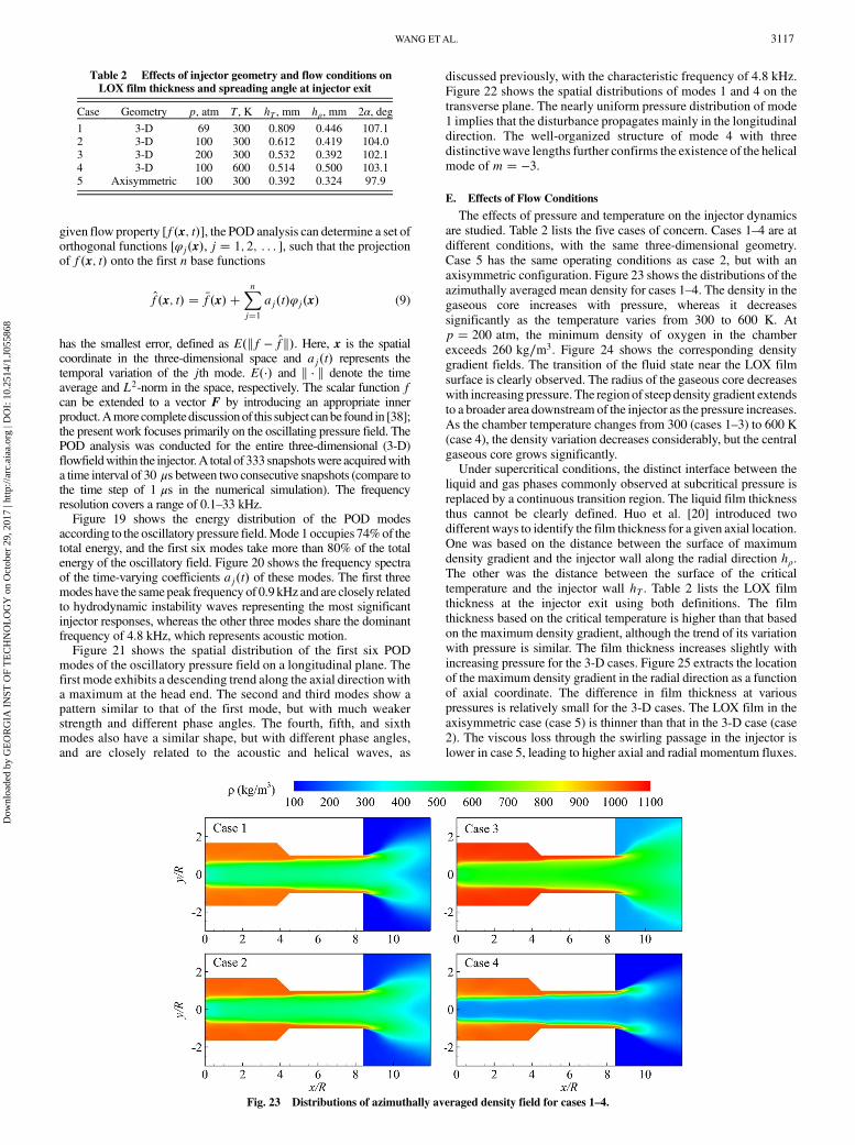
E. Effects of Flow Conditions
The effects of pressure and temperature on the injector dynamics
are studied. Table 2 lists the five cases of concern. Cases 1–4 are at
different conditions, with the same three-dimensional geometry.
Case 5 has the same operating conditions as case 2, but with an
axisymmetric configuration. Figure 23 shows the distributions of the
azimuthally averaged mean density for cases 1–4. The density in the
gaseous core increases with pressure, whereas it decreases
significantly as the temperature varies from 300 to 600 K. At
p � 200 atm, the minimum density of oxygen in the chamber
exceeds 260 kg∕m3. Figure 24 shows the corresponding density
gradient fields. The transition of the fluid state near the LOX film
surface is clearly observed. The radius of the gaseous core decreases
with increasing pressure. The region of steep density gradient extends
to a broader area downstream of the injector as the pressure increases.
As the chamber temperature changes from 300 (cases 1–3) to 600 K
(case 4), the density variation decreases considerably, but the central
gaseous core grows significantly.Under supercritical conditions, the distinct interface between the
liquid and gas phases commonly observed at subcritical pressure is
replaced by a continuous transition region. The liquid film thickness
thus cannot be clearly defined. Huo et al. [20] introduced two
different ways to identify the film thickness for a given axial location.
One was based on the distance between the surface of maximum
density gradient and the injector wall along the radial direction hρ.The other was the distance between the surface of the critical
temperature and the injector wall hT . Table 2 lists the LOX film
thickness at the injector exit using both definitions. The film
thickness based on the critical temperature is higher than that based
on the maximum density gradient, although the trend of its variation
with pressure is similar. The film thickness increases slightly with
increasing pressure for the 3-D cases. Figure 25 extracts the location
of the maximum density gradient in the radial direction as a function
of axial coordinate. The difference in film thickness at various
pressures is relatively small for the 3-D cases. The LOX film in the
axisymmetric case (case 5) is thinner than that in the 3-D case (case
2). The viscous loss through the swirling passage in the injector is
lower in case 5, leading to higher axial and radial momentum fluxes.
Table 2 Effects of injector geometry and flow conditions onLOX film thickness and spreading angle at injector exit
Case Geometry p, atm T, K hT , mm hρ, mm 2α, deg
1 3-D 69 300 0.809 0.446 107.12 3-D 100 300 0.612 0.419 104.03 3-D 200 300 0.532 0.392 102.14 3-D 100 600 0.514 0.500 103.15 Axisymmetric 100 300 0.392 0.324 97.9
Fig. 23 Distributions of azimuthally averaged density field for cases 1–4.
WANG ETAL. 3117
Dow
nloa
ded
by G
EO
RG
IA I
NST
OF
TE
CH
NO
LO
GY
on
Oct
ober
29,
201
7 | h
ttp://
arc.
aiaa
.org
| D
OI:
10.
2514
/1.J
0558
68

The liquid film thickness is therefore thinner because of theconservation of mass.Figure 25b also provides informationonLOXfilm spreading,which
is an indication of liquid atomization and mixing. Here, the spreadingangle is defined as twice the angle between the dotted symbols and theaxial centerline in the chamber. The chamber pressure has negligibleinfluence, although the spreading angle decreases slightly withincreasing temperature. It is noteworthy that the axisymmetric study(case 5) yields a much higher spreading angle than the 3-D studies(cases 1–4). Table 2 lists the spreading angle calculated from velocitycomponents at the injector exit: α � tan�uθ∕ux�. The computedangles for the 3-D studies are larger than that for the axisymmetricstudy. This discrepancy suggests that the angle obtained from velocitycomponents may not properly represent film spreading. Instead, theangles visualized from the curves ofmaximumdensity gradient exhibitthe physical behavior of spreading and are useful for exploring theinfluences of various parameters.
VI. Conclusions
A comprehensive investigation of LOX swirl injector flowdynamics has been performed at supercritical conditions. A unified
theoretical and numerical framework for general fluids wasimplemented, along with the large-eddy simulation technique. Thecomplex 3-D flow structures were presented for the first time. Unlikethe interface between liquid and gas at subcritical pressure, a smoothfluid transition regionwas identified at supercritical pressure.Variousflow instability mechanisms, including shear-layer instability,acoustic instability, centrifugal instability, and helical instability,were evaluated using the spectral analysis and proper orthogonaldecomposition techniques. Hydrodynamic instability was found toplay a dominant role in flow oscillations across the injector, and thecorresponding characteristic frequency determined by numericalsimulations showed good agreement with the prediction of theanalytical response transfer function of a swirl injector. The helicalmode m � −3 resonated with the acoustic wave at 4.8 kHz andamplified itself significantly as compared to other modes. Theconverging section reflected the waves back into the vortex chamberand only allowed some of waves with long wavelengths to betransmitted to the discharge nozzle.A parametric studywas also conducted to examine the influence of
flow conditions and geometry on the injector characteristics. Thegaseous core decreased with increasing pressure. The liquid filmthickness increased slightly with pressure. An axisymmetric studyproduced a smaller film thickness and larger spreading angle than3-D studies due to the lack of flow dynamics in the azimuthaldirection and lower momentum loss. The spreading angle defined bythe maximum density gradient provided a more physicalinterpretation of liquid spreading than the conventional definitionof the ratio of axial and tangential velocity components. Thespreading angle was nearly independent of the pressure. The resultsreported here provide a basis for future research on the mixing andcombustion of swirling flows at supercritical conditions.
Acknowledgments
This workwas sponsored by theU.S. Air ForceOffice of ScientificResearch under grant no. FA 9550-10-1-0179. The authors gratefullyacknowledge support and advice given by Mitat A. Birkan.
References
[1] Lieuwen, T. C., and Yang, V., (eds.), Combustion Instabilities in Gas
Turbine Engines (Operational Experience, Fundamental Mechanisms
and Modeling), Vol. 210, Progress in Astronautics and Aeronautics,AIAA, Reston, VA, 2005.doi:10.2514/4.866807
[2] Huang, Y., and Yang, V., “Dynamics and Stability of Lean-PremixedSwirl-Stabilized Combustion,” Progress in Energy and Combustion
Science, Vol. 35, No. 4, 2009, pp. 293–364.doi:10.1016/j.pecs.2009.01.002
Fig. 25 Distributions of local maximum density gradient in the radialdirection as a function of the axial coordinate a) within the injector, andb) downstream of the injector.
Fig. 24 Distributions of the magnitude of azimuthally averaged density gradient for cases 1–4.
3118 WANG ETAL.
Dow
nloa
ded
by G
EO
RG
IA I
NST
OF
TE
CH
NO
LO
GY
on
Oct
ober
29,
201
7 | h
ttp://
arc.
aiaa
.org
| D
OI:
10.
2514
/1.J
0558
68

[3] Bazarov, V., Yang, V., and Puri, P., “Design and Dynamics of Jet andSwirl Injectors,” Liquid Rocket Thrust Chambers: Aspects of Modeling,
Analysis, and Design, Vol. 200, Progress in Astronautics andAeronautics, edited by V. Yang, M. Habiballah, J. Hulka, and M. Popp,AIAA, Reston, VA, 2004, pp. 19–103.doi:10.2514/4.866760
[4] Rizk, N., and Lefebvre, A., “Internal Flow Characteristics of SimplexSwirl Atomizers,” Journal of Propulsion and Power, Vol. 1, No. 3,1985, pp. 193–199.doi:10.2514/3.22780
[5] Inamura, T., Tamura, H., and Sakamoto, H., “Characteristics of LiquidFilm and Spray Injected from Swirl Coaxial Injector,” Journal of
Propulsion and Power, Vol. 19, No. 4, 2003, pp. 632–639.doi:10.2514/2.6151
[6] Fu,Q.-F., Yang, L.-J., Zhang,W., andCui,K.-D., “SprayCharacteristicsof an Open-End Swirl Injector,” Atomization and Sprays, Vol. 22, No. 5,2012, pp. 431–445.doi:10.1615/AtomizSpr.v22.i5
[7] Ahn, K., Han, Y.-M., and Choi, H.-S., “Effects of Recess Length onDischarge Coefficients of Swirl Coaxial Injectors,”Combustion Scienceand Technology, Vol. 184, No. 3, 2012, pp. 323–336.doi:10.1080/00102202.2011.635615
[8] Fu, Q., and Yang, L., “Visualization Studies of the Spray from SwirlInjectors Under Elevated Ambient Pressure,” Aerospace Science and
Technology, Vol. 47, Dec. 2015, pp. 154–163.doi:10.1016/j.ast.2015.09.027
[9] Kim, D., Im, J.-H., Koh, H., and Yoon, Y., “Effect of Ambient GasDensity on Spray Characteristics of Swirling Liquid Sheets,” Journal ofPropulsion and Power, Vol. 23, No. 3, 2007, pp. 603–611.doi:10.2514/1.20161
[10] Kenny, R. J., Hulka, J. R., Moser, M. D., and Rhys, N. O., “Effect ofChamber Backpressure on Swirl Injector Fluid Mechanics,” Journal ofPropulsion and Power, Vol. 25, No. 4, 2009, pp. 902–913.doi:10.2514/1.38537
[11] Chen, X., and Yang, V., “Effect of Ambient Pressure on Liquid SwirlInjector Flow Dynamics,” Physics of Fluids, Vol. 26, No. 10, 2014,Paper 102104.doi:10.1063/1.4899261
[12] Cho, S., Park, G., Chung, Y., Yoon, Y., and Bazarov, V. G., “SurfaceInstability on Cryogenic Swirl Flow at Sub-to SupercriticalConditions,” Journal of Propulsion and Power, Vol. 30, No. 4,2014, pp. 1038–1046.doi:10.2514/1.B35071
[13] Cho, S., Kim, H., Yoon, Y., and Sung, H.-G., “Dynamic Characteristicsof a Cryogenic Swirl Flow Under Supercritical Conditions,” AerospaceScience and Technology, Vol. 51, No. 4, 2016, pp. 162–170.doi:10.1016/j.ast.2016.02.008
[14] Bazarov, V. G., and Yang, V., “Liquid-Propellant Rocket Engine InjectorDynamics,” Journal of Propulsion and Power, Vol. 14, No. 5, 1998,pp. 797–806.doi:10.2514/2.5343
[15] Wang, S., and Yang, V., “Unsteady Flow Evolution in Swirl Injectorswith Radial Entry. II. External Excitations,” Physics of Fluids (1994-
Present), Vol. 17, No. 4, 2005, Paper 045107.doi:10.1063/1.1874932
[16] Ismailov, M., and Heister, S. D., “Dynamic Response of Rocket SwirlInjectors, Part I: Wave Reflection and Resonance,” Journal of
Propulsion and Power, Vol. 27, No. 2, 2011, pp. 402–411.doi:10.2514/1.B34044
[17] Ismailov, M., and Heister, S. D., “Dynamic Response of Rocket SwirlInjectors, Part II: Nonlinear Dynamic Response,” Journal of Propulsionand Power, Vol. 27, No. 2, 2011, pp. 412–421.doi:10.2514/1.B34045
[18] Yang, V., “Modeling of Supercritical Vaporization, Mixing, andCombustion Processes in Liquid-Fueled Propulsion Systems,”Proceedings of the Combustion Institute, Vol. 28, No. 1, 2000,pp. 925–942.doi:10.1016/S0082-0784(00)80299-4
[19] Zong, N., and Yang, V., “Cryogenic Fluid Dynamics of Pressure SwirlInjectors at Supercritical Conditions,” Physics of Fluids, Vol. 20, No. 5,2008, Paper 056103.doi:10.1063/1.2905287
[20] Huo, H., Zong, N., and Yang, V., “Cryogenic Fluid Dynamic Responseof Swirl Injector to External Forcing at Supercritical Conditions,”AIAAPaper 2009-0233, 2009.doi:10.2514/6.2009-233
[21] Wang, X., Huo, H., Wang, Y., Zhang, L., and Yang, V., “A Three-Dimensional Analysis of Swirl Injector Flow Dynamics at Supercritical
Conditions,” AIAA Paper 2015-1827, 2015.doi:10.2514/6.2015-1827
[22] Oefelein, J. C., and Yang, V., “Modeling High-Pressure Mixing andCombustion Processes in Liquid Rocket Engines,” Journal of
Propulsion and Power, Vol. 14, No. 5, 1998, pp. 843–857.doi:10.2514/2.5349
[23] Erlebacher, G., Hussaini, M., Speziale, C., and Zang, T., “Toward theLarge-Eddy Simulation of Compressible Turbulent Flows,” Journal ofFluid Mechanics, Vol. 238, May 1992, pp. 155–185.doi:10.1017/S0022112092001678
[24] Wang, X., Huo, H., and Yang, V., “Supercritical Combustion of GeneralFluids in Laminar Counterflows,” AIAA Paper 2013-1165, 2013.doi:10.2514/6.2013-1165
[25] Huo, H., Wang, X., and Yang, V., “A General Study of CounterflowDiffusion Flames at Subcritical and Supercritical Conditions: Oxygen/Hydrogen Mixtures,” Combustion and Flame, Vol. 161, No. 12, 2014,pp. 3040–3050.doi:10.1016/j.combustflame.2014.06.005
[26] Wang, X., Huo, H., and Yang, V., “Counterflow Diffusion Flames ofOxygen andN-AlkaneHydrocarbons (CH4-C16H34) at Subcritical andSupercritical Conditions,” Combustion Science and Technology
Vol. 187, Nos. 1–2, 2014, pp. 60–82.doi:10.1080/00102202.2014.973955
[27] Meng, H., and Yang, V., “A Unified Treatment of General FluidThermodynamics and Its Application to a Preconditioning Scheme,”Journal of Computational Physics, Vol. 189, No. 1, 2003, pp. 277–304.doi:10.1016/S0021-9991(03)00211-0
[28] Zong, N., andYang, V., “AnEfficient Preconditioning Scheme for Real-Fluid Mixtures Using Primitive Pressure-Temperature Variables,”International Journal of Computational Fluid Dynamics, Vol. 21,Nos. 5–6, 2007, pp. 217–230.doi:10.1080/10618560701584373
[29] Hsieh, S.-Y., and Yang, V., “A Preconditioned Flux-DifferencingScheme for Chemically Reacting Flows at All Mach Numbers,”International Journal of Computational Fluid Dynamics, Vol. 8, No. 1,1997, pp. 31–49.doi:10.1080/10618569708940794
[30] Swanson, R. C., and Turkel, E., “On Central-Difference and UpwindSchemes,” Journal of Computational Physics, Vol. 101, No. 2, 1992,pp. 292–306.doi:10.1016/0021-9991(92)90007-L
[31] Rubinsky, V. R., “Instability Phenomenology and Case Studies:Combustion Instability in the RD-0110 Engine,” Liquid Rocket EngineCombustion Instability, Vol. 169, Progress in Astronautics, andAeronautics, edited by V. Yang, and W. E. Anderson, AIAA, Reston,VA, 1995, pp. 89–112.doi:10.2514/5.9781600866371.0089.0112
[32] Li, H.-G., Zong, N., Lu, X.-Y., and Yang, V., “A ConsistentCharacteristic Boundary Condition for General Fluid Mixture and ItsImplementation in a Preconditioning Scheme,” Advances in Applied
Mathematics and Mechanics, Vol. 4, No. 1, 2012, pp. 72–92.doi:10.4208/aamm.11-m1160
[33] Wang, X., and Yang, V., “Supercritical Mixing and Combustion ofLiquid-Oxygen/Kerosene Bi-Swirl Injectors,” Journal of Propulsion
and Power, Vol. 33, No. 2017, pp. 316–322.doi:10.2514/1.B36262
[34] Wang, X., Wang, Y., and Yang, V., “Geometric Effects on LiquidOxygen/Kerosene Bi-Swirl Injector Flow Dynamics at SupercriticalConditions,” AIAA Journal, 2017.doi:10.2514/1.J055952
[35] Ismailov, M., and Heister, S., “Nonlinear Modeling of Classical SwirlInjector Dynamics,” AIAA Paper 2009-5402, 2009.doi:10.2514/6.2009-5402
[36] Schadow,K., andGutmark, E., “Combustion Instability Related toVortexShedding in Dump Combustors and Their Passive Control,” Progress inEnergy and Combustion Science, Vol. 18, No. 2, 1992, pp. 117–132.doi:10.1016/0360-1285(92)90020-2
[37] Huang, Y., Wang, S., and Yang, V., “Systematic Analysis of Lean-Premixed Swirl-Stabilized Combustion,” AIAA Journal, Vol. 44, No. 4,2006, pp. 724–740.doi:10.2514/1.15382
[38] Berkooz, G., Holmes, P., and Lumley, J. L., “The Proper OrthogonalDecomposition in the Analysis of Turbulent Flows,” Annual Review of
Fluid Mechanics, Vol. 25, No. 1, 1993, pp. 539–575.doi:10.1146/annurev.fl.25.010193.002543
J. P. DrummondAssociate Editor
WANG ETAL. 3119
Dow
nloa
ded
by G
EO
RG
IA I
NST
OF
TE
CH
NO
LO
GY
on
Oct
ober
29,
201
7 | h
ttp://
arc.
aiaa
.org
| D
OI:
10.
2514
/1.J
0558
68