
Comprehensive Modelling of Renewable Energy Based ...
12
INTERNATIONAL JOURNAL of RENEWABLE ENERGY RESEARCH K. Sandeep Rao and Y. V. Pavan Kumar, Vol.11, No.1, March, 2021 Comprehensive Modelling of Renewable Energy Based Microgrid for System Level Control Studies K. Sandeep Rao, Y. V. Pavan Kumar ‡ School of Electronics Engineering, VIT-AP University, Amaravati-522237, Andhra Pradesh, INDIA ([email protected], [email protected]) ‡ Corresponding Author; Y. V. Pavan Kumar, VIT-AP University, Amaravati-522237, Andhra Pradesh, INDIA Tel: +91863-2370155, [email protected] Received: 02.02.2021 Accepted:07.03.2021 Abstract - Renewable energy will constitute the backbone of the future sustainable energy systems by forming onsite microgrids. This reduces the utility grid burden and outages. Besides, microgrids can address the issues of greenhouse gasses, global warming, fossil fuel evaporations, slow start-up/shutdown times, etc. However, their dependency on geography/climatic conditions lead to the exhibition of intermittent output characteristics. Moreover, a majority of microgrids must be interfaced with the utility grid through power electronic converters, which are static and do not possess any kinetic energy. Due to this nature, these systems are highly sensitive to events, and thereby, creating issues with fast detection of islanding during abnormalities. Furthermore, for superior power quality, stability, energy yield, reliability, and protection, they must be properly coordinated with the utility grid or neighbour microgrids via robust control mechanisms. To study all these factors, lead to a better system, it is desired to have a perfect model of the system. Many literary works have developed microgrid models by focusing on a very particular aspect or component of it with respect to their area of research. But, comprehensive models are much required for many different studies as mentioned above. Further, the comprehensive model helps in detailed system-level studies. So, with this intension, this paper proposes the development of comprehensive model of the microgrid which involves all its key characteristics/elements. Further, system-level control study is presented to persuade the importance of this proposed model. From results, the WJC method is recommended as the best method to design microgrid’s controller. Keywords Microgrids, Microgrid model, Renewable energy sources, System modelling, Control study. 1. Introduction With the rapid drifting of customer demands in the present energy sector, the depletion of fossil fuels, and environmental pollution concerns are the primary factors to look for alternate ways of electrical power generation. In this scenario, renewable energy-based microgrids are identified as a prominent solution to address these problems [1]. Besides, other major benefits are, reduction of transmission line losses and costs, reduced stress on the traditional grid, etc., [2]. However, the uncertain nature of the microgrid energy generation, low quality of power, high sensitivity to abnormalities question the fruitfulness of the microgrids. So, many studies are normally required before deployment to analyze the characteristics and behaviour of the system under certain real-time conditions. These studies include control operations, maximum power tracking capacity, fault-tolerant capacities, loading effects, momentary fault cases, voltage ride-through capabilities, system stability, supply reliability, etc. The outcome of these studies may often lead to the design of regulators and controllers as required. Hence, to perform all such tests and design of high-performance and robust controllers to address various issues, a comprehensive model of the microgrid is required. Further, the accuracy of such model influences the design accuracy of the desired controllers or schemes. Hence, the comprehensive model of the microgrid should reflect all its typical characteristics by involving all the key constituents in the model development. A good amount of research has been carried out so far for developing microgrid models in different contexts [2-4]. For instance, in the energy resource context, the development of an equivalent model for photovoltaic cells is discussed in [5-7], wind turbine based energy systems were developed in [8-10], and an equivalent model of the fuel cell performance was presented in [11-14]. Further, an inclusive of multiple
Transcript of Comprehensive Modelling of Renewable Energy Based ...

INTERNATIONAL JOURNAL of RENEWABLE ENERGY RESEARCH K. Sandeep Rao and Y. V. Pavan Kumar, Vol.11, No.1, March, 2021
Comprehensive Modelling of Renewable Energy Based Microgrid for System Level Control Studies
K. Sandeep Rao, Y. V. Pavan Kumar‡
School of Electronics Engineering, VIT-AP University, Amaravati-522237, Andhra Pradesh, INDIA
([email protected], [email protected])
‡ Corresponding Author; Y. V. Pavan Kumar, VIT-AP University, Amaravati-522237, Andhra Pradesh, INDIA
Tel: +91863-2370155, [email protected]
Received: 02.02.2021 Accepted:07.03.2021
Abstract - Renewable energy will constitute the backbone of the future sustainable energy systems by forming onsite microgrids. This reduces the utility grid burden and outages. Besides, microgrids can address the issues of greenhouse gasses, global warming, fossil fuel evaporations, slow start-up/shutdown times, etc. However, their dependency on geography/climatic conditions lead to the exhibition of intermittent output characteristics. Moreover, a majority of microgrids must be interfaced with the utility grid through power electronic converters, which are static and do not possess any kinetic energy. Due to this nature, these systems are highly sensitive to events, and thereby, creating issues with fast detection of islanding during abnormalities. Furthermore, for superior power quality, stability, energy yield, reliability, and protection, they must be properly coordinated with the utility grid or neighbour microgrids via robust control mechanisms. To study all these factors, lead to a better system, it is desired to have a perfect model of the system. Many literary works have developed microgrid models by focusing on a very particular aspect or component of it with respect to their area of research. But, comprehensive models are much required for many different studies as mentioned above. Further, the comprehensive model helps in detailed system-level studies. So, with this intension, this paper proposes the development of comprehensive model of the microgrid which involves all its key characteristics/elements. Further, system-level control study is presented to persuade the importance of this proposed model. From results, the WJC method is recommended as the best method to design microgrid’s controller.
Keywords Microgrids, Microgrid model, Renewable energy sources, System modelling, Control study.
1. Introduction
With the rapid drifting of customer demands in the present energy sector, the depletion of fossil fuels, and environmental pollution concerns are the primary factors to look for alternate ways of electrical power generation. In this scenario, renewable energy-based microgrids are identified as a prominent solution to address these problems [1]. Besides, other major benefits are, reduction of transmission line losses and costs, reduced stress on the traditional grid, etc., [2]. However, the uncertain nature of the microgrid energy generation, low quality of power, high sensitivity to abnormalities question the fruitfulness of the microgrids. So, many studies are normally required before deployment to analyze the characteristics and behaviour of the system under certain real-time conditions. These studies include control operations, maximum power tracking capacity, fault-tolerant capacities, loading effects, momentary fault cases, voltage
ride-through capabilities, system stability, supply reliability, etc. The outcome of these studies may often lead to the design of regulators and controllers as required. Hence, to perform all such tests and design of high-performance and robust controllers to address various issues, a comprehensive model of the microgrid is required. Further, the accuracy of such model influences the design accuracy of the desired controllers or schemes. Hence, the comprehensive model of the microgrid should reflect all its typical characteristics by involving all the key constituents in the model development.
A good amount of research has been carried out so far for developing microgrid models in different contexts [2-4]. For instance, in the energy resource context, the development of an equivalent model for photovoltaic cells is discussed in [5-7], wind turbine based energy systems were developed in [8-10], and an equivalent model of the fuel cell performance was presented in [11-14]. Further, an inclusive of multiple

INTERNATIONAL JOURNAL of RENEWABLE ENERGY RESEARCH K. Sandeep Rao and Y. V. Pavan Kumar, Vol.11, No.1, March, 2021
224
renewable energy sources or hybrid energy resources based models were discussed in [15, 16]. In all these works, the focus was given only to power generation modules while developing the models. The other components such as power conversion, practical loads, filtering processes, utility grid connection, etc., were not considered. Similarly, there were many different recent works presented in the literature as mentioned in Table. 1, which emphasize the model of a specific component or part of the microgrid while developing its equivalent model.
Similarly, there were some models developed to achieve certain operational benefits in microgrids. Some of these are given as follows. The total net price-based model was presented in [36]. This model was used for renewable energy system sizing as well as to design the energy management schemes. Further, the concept of energy management and its requirements were discussed in [37] in detail. Static and rotary converter efficacy in microgrids was tested in [38]. This system uses hybrid renewable energy sources. Similarly, a specific reduced-order small-signal model of AC microgrid was presented in [39]. Further, a cluster-level DC microgrid modelling was given in [40]. This was used to perform various control operations in cluster microgrids using the concept of hierarchical event-triggered consensus. However, all these models are developed to meet some specific requirement of the microgrid system operation, the concept of comprehensiveness in model development is still substandard in all these cases.
Hence, by considering the abovementioned importance of complete model development for microgrids and based on the gaps in state-of-the-art literature works, this paper presents the development of a more comprehensive yet effective model for the renewable energy-based microgrid.
Development of this comprehensive model for microgrids is the major contribution and novelty presented in this paper.
To achieve this, initially, models for each discrete component are developed and then combined all of them tactically to obtain the overall system model. Finally, an analysis of how the controller can be designed and selected based on the system response is presented using this proposed model. This analysis helps in design of suitable control systems to achieve superior benefits from microgrids.
2. Modelling of Microgrid Constituents
The usual form of the renewable energy-based microgrid that is considered for modelling is shown in Fig. 1. It consists of various elements such as energy sources, DC-to-DC and AC-to-DC converters, inverter, filter, loads, utility grid connectivity, and a closed-loop control system to regulate the output voltages. This control action is reflected via the PWM signals, which are used to modulate the inverter switches.
The first constituent is the energy resource. Three types of sources are considered in the system, viz., photovoltaics (PV), wind turbine generator (WG), and fuel cell (FC), which are commonly used in practical cases. The output voltage of all these energy sources is stepped up to one common DC level using DC-to-DC and AC-to-DC converters as required and thus forms a DC bus. This DC power is transformed to AC by passing through an inverter device. The output power of the inverter is filtered for harmonic elimination appropriately before feeding to the loads or interconnected to the utility grid. The following subsections present the development of the equivalent transfer function models of all these key constituents of the microgrid.
Table 1. Emphasized components for microgrid modelling presented in the literature
S.No Paper Theme Key Emphasis Year Reference 1 Microgrid’s small-signal model with order reduction concept Inverter 2015 [17] 2 Model of coordinated control schemes in AC microgrid Controller 2016 [18]
3 Development of the microgrid model for commercial building application Sources and Load 2016 [19]
4 Dynamic load model for the analysis of microgrid performance Load 2017 [20] 5 Model for RESS analysis with energy storage Storage unit 2018 [21] 6 Internal model-based controller for inverter-based microgrid Inverter and Controller 2018 [22] 7 Power electronic converters’ modelling for DC microgrid application Converters 2018 [23] 8 Model of an islanded no-inertia microgrid Sources and Filter 2018 [24] 9 PID controller for islanded microgrid’s voltage control Controller 2018 [25]
10 Short circuit fault-based transient model of VSC based DC microgrid Converter 2019 [26] 11 The measurement-based equivalent dynamic model of microgrids Controller and Load 2019 [27] 12 Modelling of AC and DC microgrid Sources and Converters 2019 [28] 13 Model of renewable hybrid PV-PEMFC system Energy Source 2019 [29] 14 Design of a residential PV-battery based microgrid system Sources and Converters 2020 [30] 15 Neural network-based microgrid equivalent model development Controller 2020 [31] 16 Computational model for PV cell Energy Source 2020 [32]
17 Modelling of inverter-based microgrid considering system harmonics Filter and Controller 2020 [33]
18 Model predictive control model for grid connected inverter control Controller 2020 [34] 19 System identification based simplified microgrid model Sources and Load 2020 [35]

INTERNATIONAL JOURNAL of RENEWABLE ENERGY RESEARCH K. Sandeep Rao and Y. V. Pavan Kumar, Vol.11, No.1, March, 2021
225
Fig. 1. Schematic of the microgrid system involving renewable energy.
2.1. Photovoltaic (PV) Cell Modelling
In solar panels, PV cells are the primary and significant components. In the solar panel, all the PV cells are interconnected to form a single unit. The output of the PV cell depends on environmental conditions such as solar radiation, temperature, etc. Further, it also depends on some internal factors such as, the type of material with which it is fabricated, reverse saturation current of the semiconductor component, and other parameters. To model the PV cell, many approaches were developed such as the single diode model, two diode model, multi diode model, etc., [5-7].
When the light is incident on the PV cells, the energy in the photon gets converted into the electrical current. This process can be achieved for the ideal case using the diode that is paralleled with the current source. But in practical situations, the ideal models cannot give the appropriate output. Hence, the non-ideal PV cell model that represents the practical case is achieved by connecting the series and shunt resistances to the ideal model as shown in Fig. 2. The contact resistance of the metal/semiconductor and movement of the current via base and emitter of the PV cell are included in the model by connecting the series resistance (Rseries). In the presence of low light, only a small amount of current is generated. To enumerate this problem, a shunt resistance (Rshunt) is included. The modelling equations are shown by (1) to (5), where, (1) denotes the load current passing through Rload, (2) denotes the Thevenin’s equivalent source voltage, (3) denotes Thevenin’s equivalent circuit resistance, (4) denotes the output voltage appears across Rload, and (5) denotes the system gain, i.e., the desired transfer function of the PV cell.
Fig. 2. PV cell electrical equivalent model.
(1)
(2)
(3)
(4)
(5)
2.2. Wind Turbine Generator (WG) Modelling
For modelling the WG, a simple wind turbine that is combined with a DC power generation via gear is considered [8-10]. This can be achieved by using the wind turbine with the usage of the AC generator, whose output given to the rectifier. The modelling equations of WG are given by (6) to (12). Here, (6) denotes the dynamics of the turbine, (7) denotes the dynamics of the machine, (8) and (9) denotes the machine’s electromotive force and electrical torque, (10) denotes the output current equation which is similar to (1), and (11) denotes the terminal voltage. Finally, the transfer function of WG is obtained as (12), which is similar to the transfer function of PV given in (5).
(6) (7)
(8) (9)
Thus, the equivalent electrical circuit of the WG is similar to that of PV with the following changes: Ipvs ~ IWC, id ~ IN, Rshunt
~ REQ, Rseries ~ RM. (10) (11)
(12)
Where, JTB, JMC are the moment of inertia of the turbine and machine respectively; BTB, BMC are the friction coefficient of the turbine and machine respectively; ꞶTB, ꞶMC are the
DC-DC
DC-DC
AC-DC
PV
WG
FC
Sources Converters
InverterFilter
Load
Utility Grid
S4
S1
S2
S3L
C
R
DC bus AC bus
PWM Generator Controller
S4
S1
S2
S3L
C
R
Voltage Sensor
VactVrefPWM Signals
}Rshunt
Rseries
Rload
Vout
+
-Ipvs
i
id
out seriespvs d
shunt
V iRi I i
Ræ ö+
= - - ç ÷è ø
th pvs shuntV I R= ´
th series shuntR R R= +
loadout th
th load
RV V
R R= ´
+
out load
th series shunt load
V RV R R R
=+ +
TB TB TB TB W MB J T Tw w+ = -
MC MC MC MC MC EJ B T Tw w+ = -
EL TMT K i=
T MCe K w=
WC N EQi I I eR= - -
MV e iR= -
out load
th M EQ load
V RV R R R
=+ +

INTERNATIONAL JOURNAL of RENEWABLE ENERGY RESEARCH K. Sandeep Rao and Y. V. Pavan Kumar, Vol.11, No.1, March, 2021
226
angular speed of the turbine and machine respectively; Tw is the torque produced by the wind; TM is the torque of the machine; TMC is mechanical torque; TE is electrical torque; KT
is the machine’s torque constant; IWC is wind current; IN is the nonlinear current (= (1-η)IWC); η is the power coefficient that represents the power conversion efficiency of mechanical energy to electrical energy; RM is the machine’s phase resistance.
2.3. Fuel Cell (FC) Modelling
Among the considered renewable energy sources, PV and WG efficacy depends on the environmental conditions. The FC overcomes this problem, as the operation of the FC is converting the chemical energy to electrical energy. Many types of fuel cells were developed such as Methanol sourced FC, Alkaline FC, Proton Exchange Membrane (PEM) FC, Solid Oxide FC, etc. In these, PEM FC is the most commonly used because of its high power and energy densities as well as low operating temperature. The electrical equivalent circuit of the Proton Exchange Membrane FC is used in this paper as shown in Fig. 3. For developing this circuit model, the concentration losses, activation losses, and ohmic losses are considered [11-13].
Fig. 3. FC electrical equivalent model.
(13)
(14)
(15)
The modelling equations of FC are shown through (13) to (15). Where, Vin, Vout denotes the input and output voltages respectively. Ra, Rc, Ro denotes the activation losses, concentration losses, and ohmic losses respectively. Equation (13) gives the load voltage, (14) gives the source equivalent resistance, and (15) gives the system transfer function.
2.4. Boost Converter Modelling
The boost converter is a nonlinear system, so, the transfer function method can’t be used directly to develop its model. Hence, for modelling of the boost converter system, the state-space (SS) method is used and finally, the transfer function can be obtained by linearizing the system equations [41]. The
general SS model is represented by (16), which is the combination of state equation ( ) and output equation (Y). The matrices of the system relations, input, output, and feed-forward relations are denoted as A, B, C, and D respectively. Similarly, X, Y, and U denote the state vector, output vector, and the input vector respectively.
(16)
The boost converter operation includes two states. In state-1, the switch is on as shown in Fig.4(a) and in state-2, the switch is off as shown in Fig.4(b). The resultant modelling equations are derived as given by (17) to (29) in the following steps.
Fig. 4. Boost converter modes of operation.
Step-1: Obtaining SS Model of State-1
From Kirchhoff voltage and current laws,
(17)
(18)
Therefore, the SS form is,
(19)
(20)
Step-2: Obtaining SS Model of State-2
From Kirchhoff voltage and current laws,
(21)
(22)
Therefore, the SS form is,
(23)
Vin
Ra
1/Cs
RoRload
Rc
+
-Vout
* loadout in
load EQ
RV V
R R=
+
( ) 1
1a c
EQ o
a c
R RCsR R
R RCs
é ù+ ´ê ú= + ê ú
ê ú+ +ê úë û
( )( )( ) ( )
11
out
in
load a c
a c load o a c a c o
VV
R R Cs R CsCs R R R R Cs R R R R R
ü\ = ï
ïý+ + ïï+ + + + + + + þ
X!
and X AX BU Y CX DU= + = +!
C
+ -
ONState
Load
L
C
+-OFFState L
oad
L
(b)(a)
vin vin
0Lin
div Ldt
- =
0c cv dvC
R dt+ =
[ ] [ ]0
0 0 110 0
0 1
L
Lin
cc
L
c
diidt vLvdv
RCdti
vv
üé ùé ù é ù ïê ú é ùê ú ê ú ïê ú = +- ê úê ú ê ú ïê ú ë û ê úê ú ë ûë û ýê úë û ï
ïé ù= ïê ú
ë û þ
[ ] [ ]1 1 1 1
0 0 1, , 0 1 , 010 0
A B C DLRC
é ù é ùê ú ê ú\ = = = =-ê ú ê ú
ê úê ú ë ûë û
0Lin c
div v Ldt
- - =
0c cLv dv
i CR dt
- - =
[ ] [ ]0
1 10
1 1 0
0 1
L
Lin
cc
L
c
diidt L vLvdv
C RCdti
vv
ü-é ù é ù é ù ïê ú ê ú é ù ê ú ïê ú = +ê ú ê ú ê ú- ïê ú ê ú ë û ê úë û ýê ú ê úë ûë û ïïé ù
= ïê úë û þ

INTERNATIONAL JOURNAL of RENEWABLE ENERGY RESEARCH K. Sandeep Rao and Y. V. Pavan Kumar, Vol.11, No.1, March, 2021
227
(24)
Step-3: Obtaining SS Model of the Total Circuit
The SS model of the overall circuit can be obtained by finding the average of the above two steps. Hence, by using the state-space averaging method given in (25), the average of (20) and (24) is obtained as (26).
(25)
(26)
Step-4: Obtaining Transfer Function of the Total Circuit
The combined SS model obtained in (26) is converted to the transfer function representation by using (27). Hence, the overall system transfer function is derived as (28). Where ‘r’ represents the duty ratio. By assuming a smaller value for ‘r’, (28) is simplified as (29).
(27)
(28)
(29)
2.5. Converters (AC-to-DC and DC-to-AC) Modelling
Generally, to convert the AC to DC and to convert DC to AC, diode-based or any other controlled semiconductor-based rectifiers and inverters are used respectively [42]. Especially, the operation of the inverters depends on the state of the switches, such as MOSFET, IGBT, Thyristors, etc. The inverter operates in two modes as shown in Fig. 5. In mode-1, switches S1 and S2 are switched on, S3 and S4 are off, which produces a positive step in the output. Similarly, in mode-2, switches S3 and S4 are on, S1 and S2 are switched off, which produces the negative step in the output. Now by increasing
the number of steps, a waveform that is more approximated to the sine wave is obtained. The increase in steps can be obtained by increasing the number of switches, which are called multilevel inverters [43].
Fig. 5. DC-AC converter and its modes of operation.
However, as all these components hold lower power losses, their effect in high power circuits like microgrids is negligible. Hence, the transfer function of these converters (rectifier/inverter) is approximated to unity in this paper.
2.6. Filter Circuitry Modelling
The inverted output is usually non-sinusoidal due to the stepped nature injected by the switching devices, which is termed as the harmonic voltage. So, to obtain the desired waveform closer to the sinusoidal nature, the output of the inverter is passed through a filter device before feeding it to the load or utility grid. For this purpose, a low pass RLC filter is used as shown in Fig. 6. The model of this circuit is derived as given in (30), where, Vout denotes the voltage across the capacitor (output voltage) and Vin denotes the inverter output voltage that is given as input to the filter [44].
(30)
Fig. 6. Filter equivalent circuit.
2.7. Load Modelling
Three different types of loads are considered for the load circuit modelling as shown in Fig. 7. In this, one dominant inductive load branch is considered to represent large power consumers or industrial applications, such as transformers, induction furnaces, gaseous tube lighting ballasts, etc. Similarly, a dominant capacitive load branch is considered to represent synchronous motors, motor starter circuits, power factor corrective equipment, etc. Further, the combination of
[ ] [ ]2 1 1 1
1 10, , 0 1 , 0
1 1 0
LA B C DL
C RC
-é ù é ùê ú ê ú\ = = = =ê ú ê ú-ê ú ê úë ûê úë û
1 2 1 2
1 2 1 2
(1 ) (1 )(1 ) (1 )
A r A r B r B rA BC r C r D r D rC D
+ - + -é ùé ù= ê úê ú + - + -ë û ë û
( )
( )
[ ] [ ]( ) [ ][ ] [ ]( ) [ ]
1 10 0 0 011 1 1 1 10
1 1 11
0 0 0
0 1 0 1 1 0 1
0 0 1 0
rL LA r r
rRC C RC C RC
B r rL L L
C r r
D r r
ü- -é ù é ùé ù ïê ú ê úê ú ï\ = + - =ê ú ê ú-ê ú - - - ïê ú ê úê úë û ïê ú ê úë û ë ûïïé ù é ù é ù ýê ú ê ú ê ú\ = + - = ïê ú ê ú ê ú ïê ú ê ú ê úë û ë û ë û ïï\ = + - =ï
\ = + - = ïþ
( ) 1( )( )Y s C sI A B DU s
-= - +
[ ] [ ]
1
2 2
1 101 0( ) 0 1 01 10 1( ) 0
( ) (1 )( ) (1 )
rY s Ls L
rU sC RC
Y s R rU s RCLs Ls R r
- üæ ö-é ù ïé ùç ÷ê úé ù ïê úç ÷= - +ê úê ú ïê ú- ïç ÷ê úë û - ê ú ýë ûç ÷ê úë ûè ø ïï-
Þ = ï+ + - ïþ
2
( )( )Y s RU s RCLs Ls R
=+ +
V
S4
S1
S2
S3
Load
S1
S2
V
Load
S3
S4
V
LoadMode
1 2Mode
2
1 11 1
out
in
V CsV LCs RCsLs R Cs
= =+ ++ +
R Ls
1/Cs Vout
+
-
Vin

INTERNATIONAL JOURNAL of RENEWABLE ENERGY RESEARCH K. Sandeep Rao and Y. V. Pavan Kumar, Vol.11, No.1, March, 2021
228
an inductive and resistive branch is chosen to represent domestic or medium current applications such as motors, fans, etc. The series resistor represents the transmission losses. The modelling of the load is given in (31) to (32), where, (31) represents the voltage across the capacitor (output voltage) and (32) represents the gain or transfer function of the load circuit. For convenience, it is assumed that all the inductor loads are the same (i.e., L1=L2=L) and all the resistances are the same (i.e., R1=R2=R).
Fig. 7. Load equivalent circuit.
(31)
(32)
3. Model of the Total Microgrid System
The logical diagram shown in Fig. 8 is developed as a combination of all the key constituents that are modelled in the previous section, to derive the transfer function of the overall microgrid system. Where,
§ X = Transfer function of PV derived as (5) × Transfer function of boost converter derived as (29). This is obtained as given in (33).
(33)
§ Y = Transfer function of WG derived as (12) × Transfer function of the AC/DC converter. This is obtained as given in (34).
(34)
§ Z = Transfer function of FC derived as (15) × Transfer function of boost converter derived as (29). This is obtained as given in (35).
(35)
Fig. 8. The logical diagram to obtain the overall microgrid
system transfer function.
Hence, the total model can be obtained as a combination of (30), (32), (33), (34), (35) that are arranged in a sequence as given in Fig. 8. This is computed as (36). This final model can be appropriately simplified based on the substitution of its parameter values that are designed for the considered application. For simplicity, this paper assumes the value of all the resistors equal to 1 ohm, capacitors equal to 1 farad, and inductors equal to 1 henry. Hence, the final simplified transfer function model of the overall microgrid system is derived as given in (37).
4. System-Level Control Study of the Microgrid with Simulation Results
In the area of control system studies, the system transfer function has a critical role. This helps in the design of various control logics and further adjustment of effective control parameters to obtain user desired responses from the system. Especially in the microgrid context, the transfer function is useful in many ways, such as to design maximum power tracking algorithms, droop control mechanisms to optimally share the energy resources between multiple loads, islanding mechanisms, the study on control operations to see the impact on system response, etc.
To persuade the importance of the proposed comprehensive transfer function model in this paper, control studies are performed to understand how the controller design influences the system response. To do this, three test cases are executed as given follows and the observations are summarized in the following subsections. The system schematic shown in Fig. 9 is realized in the Simulink tool for the control study.
(36)
(37)
R1
1/Cs Vout
+
-
VinL1s
R2
L2s
1/ /( ) / /
1/ /( ) / /out in
Ls Ls RCsV V
R Ls Ls RCs
æ ö+ç ÷è ø=
é ùæ ö+ +ç ÷ê úè øë û
( ) ( )2 3 2 2
2 4 2 3 2 2
22 1
out
in
V L Cs RLCs RLs RV RLC L R s L Cs RLC R s R Cs
+ + +\ =
+ + + + +
( )( )
2
2
load
series shunt load
load
series shunt load
R RXR R R RLCs Ls R
R RR R R RLCs Ls R
üæ ö æ ö= ´ ïç ÷ ç ÷+ + + +è ø ïè øý´ ï=ï+ + + + þ
( )1load load
M EQ load M EQ load
R RY
R R R R R Ræ ö
= ´ =ç ÷ç ÷+ + + +è ø
( )( )( ) ( )
2
11
load a c
a c load o a c a c o
ZR R Cs R Cs
Cs R R R R Cs R R R R R
RRLCs Ls R
üï= ïï+ + ïý
+ + + + + + + ïïï´ï+ + þ
DC/DC
AC/DC
DC/DC
Inverter Filter
PV
WG
FC
Load
X
Y
Z
( ) ( ) ( ) ( )2 3 2 2
2 2 4 2 3 2 2
1 2. . . 11 2 1
L Cs RLCs RLs RT T F X Y Zs LC sRC RLC L R s L Cs RLC R s R Cs
æ ö+ + +æ ö\ = + + ´ ´ ´ç ÷ç ÷ ç ÷+ + + + + + +è ø è ø
8 7 6 5 4 3 2
11 10 9 8 7 6 5 4 3 2
12 72 197 322 330 223 96 18. . .12 84 315 768 1389 1884 1965 1593 984 453 144 27
s s s s s s s sT T Fs s s s s s s s s s s
+ + + + + + +Þ =
+ + + + + + + + + + +

INTERNATIONAL JOURNAL of RENEWABLE ENERGY RESEARCH K. Sandeep Rao and Y. V. Pavan Kumar, Vol.11, No.1, March, 2021
229
Fig. 9. Schematic of the closed-loop control system formed with the comprehensive transfer function.
Fig. 10. Simulink model of the microgrid with PID controller tested with various gain values and disturbance.
§ Case-1: Analysis of the impact of the controller on the system response
§ Case-2: Analysis of the impact of the controller on the system gain
§ Case-3: Analysis and selection of the best controller for the microgrid application
4.1. Analysis of the Controller’s Impact on System Response
To understand the impact of the controller on the system response, the microgrid’s closed-loop control system schematic shown in Fig. 9 is simulated with and without the controller and disturbance. Proportional-Integral-Derivative (PID) controller, which is a widely used controller for many practical and industrial applications is used as the controller in this study. Different gain parameters are applied to the PID controller and observed its influence on the system response under the normal operating condition as well as under disturbance condition. The corresponding simulation model used to study all these variations is shown in Fig. 10.
4.1.1. System Response Analysis with and without Controller Under No-Disturbance
In this analysis, the system response is analyzed with and without the inclusion of the controller in the system. The PID controller gain parameters are designed using the standard methods described in [45]. The corresponding simulation results are shown in Fig. 11 - Fig. 13. From these results, it is observed that the response of the system without the controller doesn’t reach the required output i.e., 1pu as
shown in Fig. 11. So, there is a need for the controller so that the required output can be achieved. Consequently, a PID controller is placed in the system and the corresponding system response is obtained as given in Fig. 12. This inclusion of the controller pushed the response to a level of the desired magnitude.
Fig. 11. Step response of the microgrid system without the
use of any controller.
Fig. 12. Step response of the microgrid system with the
inclusion of the PID controller.
8 7 6 5 4 3 2
11 10 9 8 7 6 5 4 3 212 72 197 322 330 223 96 18
12 84 315 768 1389 1884 1965 1593 984 453 144 27s s s s s s s s
s s s s s s s s s s s+ + + + + + +
+ + + + + + + + + + +PID(s)+_
8 7 6 5 4 3 2
11 10 9 8 7 6 5 4 3 212 72 197 322 330 223 96 18
12 84 315 768 1389 1884 1965 1593 984 453 144 27s s s s s s s s
s s s s s s s s s s s+ + + + + + +
+ + + + + + + + + + +
8 7 6 5 4 3 2
11 10 9 8 7 6 5 4 3 212 72 197 322 330 223 96 18
12 84 315 768 1389 1884 1965 1593 984 453 144 27s s s s s s s s
s s s s s s s s s s s+ + + + + + +
+ + + + + + + + + + +
8 7 6 5 4 3 2
11 10 9 8 7 6 5 4 3 212 72 197 322 330 223 96 18
12 84 315 768 1389 1884 1965 1593 984 453 144 27s s s s s s s s
s s s s s s s s s s s+ + + + + + +
+ + + + + + + + + + +
8 7 6 5 4 3 2
11 10 9 8 7 6 5 4 3 212 72 197 322 330 223 96 18
12 84 315 768 1389 1884 1965 1593 984 453 144 27s s s s s s s s
s s s s s s s s s s s+ + + + + + +
+ + + + + + + + + + +

INTERNATIONAL JOURNAL of RENEWABLE ENERGY RESEARCH K. Sandeep Rao and Y. V. Pavan Kumar, Vol.11, No.1, March, 2021
230
Further, a stability response plot is drawn as shown in Fig. 13. From this, it is noticed that the system with the controller is more stable than the system without the controller based on the computation of phase margin and gain margin of the responses.
Fig. 13. The frequency response of the microgrid system
with and without the controller.
4.1.2. System Response Analysis with Controller and with Disturbance
Another interesting case study is the analysis of the system performance during disturbances. As shown in Fig. 10, for doing this study, the controller with different PID gains with a common disturbance of magnitude 20% of the reference input is injected into the system at the time interval 150sec and removed at 250sec. The responses obtained in this study are plotted as shown in Fig.14. Though the disturbance rejection is different for different PID gain parameter values, from Fig.15, it can be observed that all the responses are stable as all the poles lie on the left half of the s-plane. Further, it can be observed that the impact of disturbance is different for different controller gains. So, this analysis helps to identify better PID gain values to provide good disturbance rejection capability to the microgrid system, which improves its stability.
Fig. 14. The response of the microgrid system under a
disturbance with variable PID gains.
Fig. 15. Stability response of the microgrid system under a
disturbance with variable PID gains.
4.2. Analysis of the Controller’s Impact on System Gain
From the analysis presented in Section 4.1, it is clear that the controller produces the desired response under all conditions. However, effective gain parameters have to be set for the controller to achieve this. In the PID controller, there are three critical parameters, viz., proportional parameter (KP), derivative parameter (KD), and integral parameter (KI).
Fig. 16. Stability response of the microgrid system with
different controller gains.
Fig. 17. Step response of the microgrid system with different
controller gain values.
So, the system responses with varying PID gain parameters are plotted as shown in Fig. 16 and Fig. 17. From Fig. 16, the stability analysis plot, it is observed that though there is a variation in PID gain parameters, all the responses are stable based on the identification of all corresponding system poles, which lies on the left half of the s-plane. From Fig. 17, it is seen clearly how the variation of gain parameters vary the system gain.
4.3. Analysis and Selection of the Best Controller for the Microgrid Application
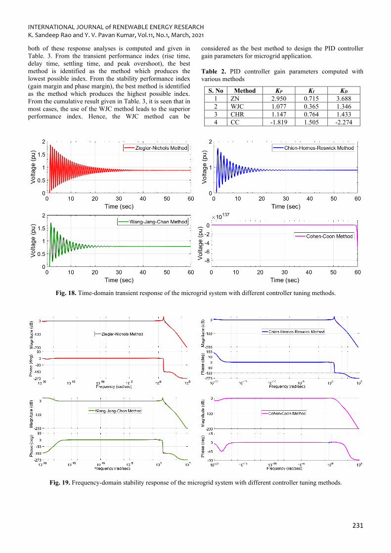
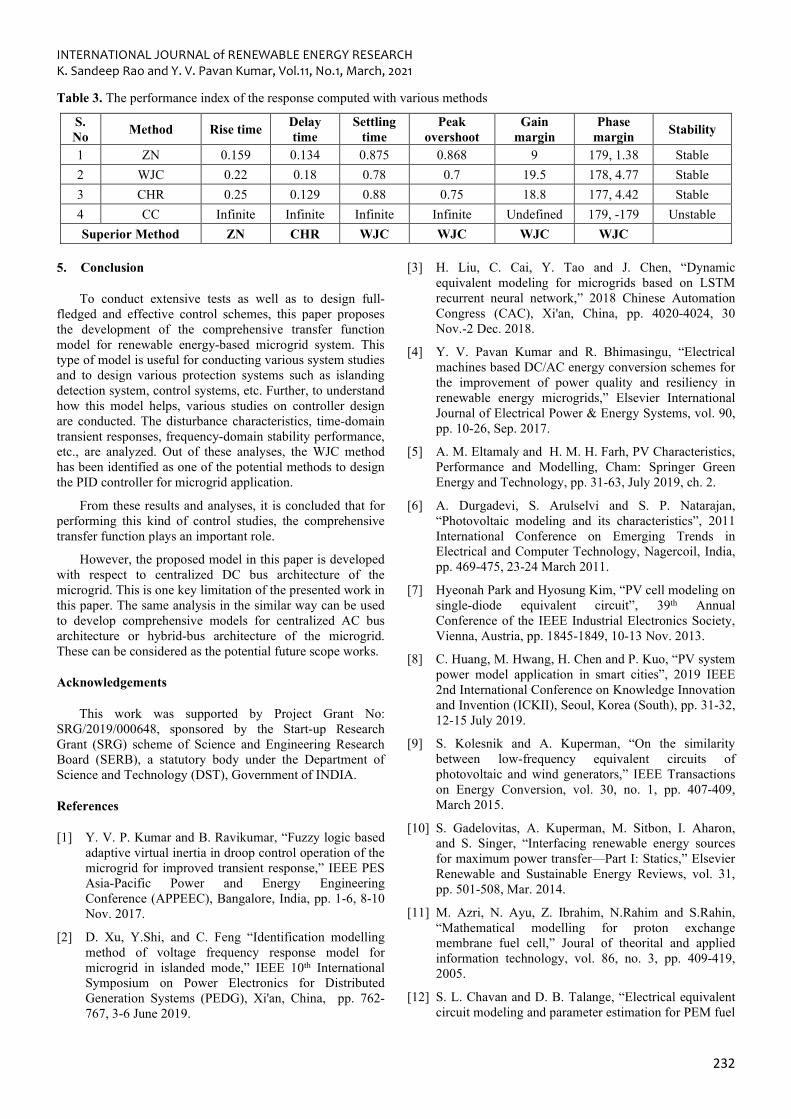
From the analysis presented in Section 4.1 and 4.2, it is clear that the controller with suitable gain parameters can regulate the system response under normal as well as disturbance conditions. So, to identify the precise and best gain parameters for the PID controller, various standard methods, viz., Ziegler-Nichols (ZN), Chien-Hrones-Reswick (CHR), Wang-Jang-Chan (WJC), and Cohen-Coon (CC) are implemented [45]. The corresponding gain parameters are calculated and given in Table. 2. Time-domain transient response analysis and frequency-domain stability analysis are conducted to identify the superior method out of these.
The simulation results of the executed analyses are given in Fig. 18 and Fig. 19. The various performance index of
INTERNATIONAL JOURNAL of RENEWABLE ENERGY RESEARCH K. Sandeep Rao and Y. V. Pavan Kumar, Vol.11, No.1, March, 2021
231
both of these response analyses is computed and given in Table. 3. From the transient performance index (rise time, delay time, settling time, and peak overshoot), the best method is identified as the method which produces the lowest possible index. From the stability performance index (gain margin and phase margin), the best method is identified as the method which produces the highest possible index. From the cumulative result given in Table. 3, it is seen that in most cases, the use of the WJC method leads to the superior performance index. Hence, the WJC method can be
considered as the best method to design the PID controller gain parameters for microgrid application.
Table 2. PID controller gain parameters computed with various methods
S. No Method KP KI KD 1 ZN 2.950 0.715 3.688 2 WJC 1.077 0.365 1.346 3 CHR 1.147 0.764 1.433 4 CC -1.819 1.505 -2.274
Fig. 18. Time-domain transient response of the microgrid system with different controller tuning methods.
Fig. 19. Frequency-domain stability response of the microgrid system with different controller tuning methods.
INTERNATIONAL JOURNAL of RENEWABLE ENERGY RESEARCH K. Sandeep Rao and Y. V. Pavan Kumar, Vol.11, No.1, March, 2021
232
Table 3. The performance index of the response computed with various methods
S. No Method Rise time Delay
time Settling
time Peak
overshoot Gain
margin Phase
margin Stability
1 ZN 0.159 0.134 0.875 0.868 9 179, 1.38 Stable 2 WJC 0.22 0.18 0.78 0.7 19.5 178, 4.77 Stable 3 CHR 0.25 0.129 0.88 0.75 18.8 177, 4.42 Stable 4 CC Infinite Infinite Infinite Infinite Undefined 179, -179 Unstable Superior Method ZN CHR WJC WJC WJC WJC
5. Conclusion
To conduct extensive tests as well as to design full-fledged and effective control schemes, this paper proposes the development of the comprehensive transfer function model for renewable energy-based microgrid system. This type of model is useful for conducting various system studies and to design various protection systems such as islanding detection system, control systems, etc. Further, to understand how this model helps, various studies on controller design are conducted. The disturbance characteristics, time-domain transient responses, frequency-domain stability performance, etc., are analyzed. Out of these analyses, the WJC method has been identified as one of the potential methods to design the PID controller for microgrid application.
From these results and analyses, it is concluded that for performing this kind of control studies, the comprehensive transfer function plays an important role.
However, the proposed model in this paper is developed with respect to centralized DC bus architecture of the microgrid. This is one key limitation of the presented work in this paper. The same analysis in the similar way can be used to develop comprehensive models for centralized AC bus architecture or hybrid-bus architecture of the microgrid. These can be considered as the potential future scope works.
Acknowledgements
This work was supported by Project Grant No: SRG/2019/000648, sponsored by the Start-up Research Grant (SRG) scheme of Science and Engineering Research Board (SERB), a statutory body under the Department of Science and Technology (DST), Government of INDIA.
References
[1] Y. V. P. Kumar and B. Ravikumar, “Fuzzy logic based adaptive virtual inertia in droop control operation of the microgrid for improved transient response,” IEEE PES Asia-Pacific Power and Energy Engineering Conference (APPEEC), Bangalore, India, pp. 1-6, 8-10 Nov. 2017.
[2] D. Xu, Y.Shi, and C. Feng “Identification modelling method of voltage frequency response model for microgrid in islanded mode,” IEEE 10th International Symposium on Power Electronics for Distributed Generation Systems (PEDG), Xi'an, China, pp. 762-767, 3-6 June 2019.
[3] H. Liu, C. Cai, Y. Tao and J. Chen, “Dynamic equivalent modeling for microgrids based on LSTM recurrent neural network,” 2018 Chinese Automation Congress (CAC), Xi'an, China, pp. 4020-4024, 30 Nov.-2 Dec. 2018.
[4] Y. V. Pavan Kumar and R. Bhimasingu, “Electrical machines based DC/AC energy conversion schemes for the improvement of power quality and resiliency in renewable energy microgrids,” Elsevier International Journal of Electrical Power & Energy Systems, vol. 90, pp. 10-26, Sep. 2017.
[5] A. M. Eltamaly and H. M. H. Farh, PV Characteristics, Performance and Modelling, Cham: Springer Green Energy and Technology, pp. 31-63, July 2019, ch. 2.
[6] A. Durgadevi, S. Arulselvi and S. P. Natarajan, “Photovoltaic modeling and its characteristics”, 2011 International Conference on Emerging Trends in Electrical and Computer Technology, Nagercoil, India, pp. 469-475, 23-24 March 2011.
[7] Hyeonah Park and Hyosung Kim, “PV cell modeling on single-diode equivalent circuit”, 39th Annual Conference of the IEEE Industrial Electronics Society, Vienna, Austria, pp. 1845-1849, 10-13 Nov. 2013.
[8] C. Huang, M. Hwang, H. Chen and P. Kuo, “PV system power model application in smart cities”, 2019 IEEE 2nd International Conference on Knowledge Innovation and Invention (ICKII), Seoul, Korea (South), pp. 31-32, 12-15 July 2019.
[9] S. Kolesnik and A. Kuperman, “On the similarity between low-frequency equivalent circuits of photovoltaic and wind generators,” IEEE Transactions on Energy Conversion, vol. 30, no. 1, pp. 407-409, March 2015.
[10] S. Gadelovitas, A. Kuperman, M. Sitbon, I. Aharon, and S. Singer, “Interfacing renewable energy sources for maximum power transfer—Part I: Statics,” Elsevier Renewable and Sustainable Energy Reviews, vol. 31, pp. 501-508, Mar. 2014.
[11] M. Azri, N. Ayu, Z. Ibrahim, N.Rahim and S.Rahin, “Mathematical modelling for proton exchange membrane fuel cell,” Joural of theorital and applied information technology, vol. 86, no. 3, pp. 409-419, 2005.
[12] S. L. Chavan and D. B. Talange, “Electrical equivalent circuit modeling and parameter estimation for PEM fuel

INTERNATIONAL JOURNAL of RENEWABLE ENERGY RESEARCH K. Sandeep Rao and Y. V. Pavan Kumar, Vol.11, No.1, March, 2021
233
cell,” 2017 Innovations in Power and Advanced Computing Technologies (i-PACT), Vellore, India, pp. 1-6, 21-22 April 2017.
[13] J. Zhu, S. Wu, X. Luo and S. Liu, “Equivalent voltage and current models for PEM fuel cell generation system in grid-connected systems,” 2014 17th International Conference on Electrical Machines and Systems (ICEMS), Hangzhou, China, pp. 308-313, 22-25 Oct. 2014.
[14] V. Boscaino, R. Miceli, G. Capponi, and D. Casadei, “Fuel cell modelling and test: Experimental validation of model accuracy,” 4th International Conference on Power Engineering, Energy and Electrical Drives, Istanbul, Turkey, pp. 1795-1800, 13-17 May 2013.
[15] N. Beg, A. Armstorfer, A. Rosin and H. Biechl, “Mathematical Modeling and Stability Analysis of a Microgrid in Island Operation,” 2018 International Conference on Smart Energy Systems and Technologies (SEST), Seville, Spain, pp. 1-6, 10-12 Sept. 2018.
[16] R. Stanev, T. Simeonov and T. Asenov, “Mathematical modelling of micro and nanogrids with distributed generation,” 2018 Seventh Balkan Conference on Lighting (BalkanLight), Varna, pp. 1-4, 20-22 Sept. 2018.
[17] M. Rasheduzzaman, A. M. Jacob, and W. K. Jonathan, “Reduced-order small signal model of microgrid system,” IEEE Transactions on Sustainable Energy, vol. 6, no. 4, pp. 1292-1305, Oct. 2015.
[18] H. Wen, H. Yu and Y. Hu, “Modeling and analysis of coordinated control strategies in AC microgrid,” 2016 IEEE International Conference on Renewable Energy Research and Applications (ICRERA), Birmingham, UK, pp. 702-707, 20-23 Nov. 2016.
[19] L. Meghapola and D. Robinson, Dynamic Modelling, Simulation and Control of a Commercial Building Microgrid,” Cham: Springer Studies in Systems, Decision and Control, vol. 57, pp.119-140, Mar. 2016, ch. 7.
[20] D. Choi, J. Yoo, D. Kim, S. H. Lee and J. Park, “Analysis on Effect of SFCL Applied to an Isolated Microgrid With a Dynamic Load Model,” IEEE Transactions on Applied Superconductivity, vol. 27, no. 4, pp. 1-4, June 2017.
[21] P. Mazidi, G. N. Baltas, M. Eliassi and P. Rodríguez, “A Model for Flexibility Analysis of RESS with Electric Energy Storage and Reserve,” 2018 7th International Conference on Renewable Energy Research and Applications (ICRERA), Paris, France, pp. 1004-1009, 14-17 Oct. 2018.
[22] S. Leitner, M. Yazdanian, A. Mehrizi-Sani and A. Muetze, “Small-Signal Stability Analysis of an Inverter-Based Microgrid With Internal Model-Based Controllers,” IEEE Transactions on Smart Grid, vol. 9, no. 5, pp. 5393-5402, Sept. 2018.
[23] A. Francés, R. Asensi, Ó. García, R. Prieto and J. Uceda, “Modeling Electronic Power Converters in Smart DC Microgrids-An Overview,” IEEE Transactions on Smart Grid, vol. 9, no. 6, pp. 6274-6287, Nov. 2018.
[24] A. Bonfiglio, F. Delfino, A. Labella, M. Daniele, P. Fabio, P. Renato, and J. M. Guerrero “Modeling and Experimental Validation of an Islanded No-Inertia Microgrid Site,” IEEE Transactions on Sustainable Energy, vol. 9, no. 4, pp. 1812-1821, Oct. 2018.
[25] S. K. Sarkar, F. R. Badal, and K. S. Das, “A comparative study of high performance robust PID controller for grid voltage control of islanded microgrid,” Springer International Journal of Dynamics Control, pp. 1207-1217, 2018.
[26] H. Nian and L. Kong, “Transient Modeling and Analysis of VSC Based DC Microgrid During Short Circuit Fault,” IEEE Access, vol. 7, pp. 170604-14, Nov. 2019.
[27] B. Zaker, G. B. Gharehpetian and M. Karrari, “A Novel Measurement-Based Dynamic Equivalent Model of Grid-Connected Microgrids,” IEEE Transactions on Industrial Informatics, vol. 15, no. 4, pp. 2032-2043, April 2019.
[28] N. R. Rahmanov, O. Z. Karimov, “AC and DC Combined Microgrid, Modeling and Operation,” Cham: Springer Microgrid Architectures, Control and Protection Methods, pp. 47-68, July 2019.
[29] Bassam Zafar, “Design of a renewable hybrid photovoltaic electrolyze-PEM/fuel cell system using hydrogen gas,” International Journal of Smart Grid, vol. 3, no. 4, pp. 201-207, Dec. 2019.
[30] M. Alramlawi and P. Li, “Design Optimization of a Residential PV-Battery Microgrid With a Detailed Battery Lifetime Estimation Model,” IEEE Transactions on Industry Applications, vol. 56, no. 2, pp. 2020-2030, March-April 2020.
[31] C. Cai, H. Liu, Y. Tao, Z. Deng, W. Dai and J. Chen, “Microgrid Equivalent Modeling Based on Long Short-Term Memory Neural Network,” IEEE Access, vol. 8, pp. 23120-23133, Jan. 2020.
[32] G. Todeschini, H. Huang, N. Bristow, T. W. David, J. Kettle, “A novel computational model for organic pv cells and modules,” International Journal of Smart Grid, vol 4, no 4, pp. 157-163, Dec. 2020.
[33] Y. Peng, Z. Shuai, X. Liu, Z. Li, J. M. Guerrero and Z. J. Shen, “Modeling and Stability Analysis of Inverter-Based Microgrid Under Harmonic Conditions,” IEEE Transactions on Smart Grid, vol. 11, no. 2, pp. 1330-1342, Mar. 2020.
[34] H. Mirshekali, R. Dashti, H. R. Shaker and R. Samsami, “A new model predictive control based method for control of grid connected inverter using predictive functional control," 2020 IEEE 8th International Conference on Smart Energy Grid

INTERNATIONAL JOURNAL of RENEWABLE ENERGY RESEARCH K. Sandeep Rao and Y. V. Pavan Kumar, Vol.11, No.1, March, 2021
234
Engineering (SEGE), Oshawa, ON, Canada, pp. 22-26, 12-14 Aug. 2020.
[35] Y. Shi, H. Sunan, D. Xu, S. Jianhui, N. Liu, X. Yang, Y. Du, “A simplified microgrid voltage and frequency response characteristic modelling method based on system identification,” Elsevier International Journal of Electrical Power & Energy Systems, vol. 121, Oct. 2020.
[36] Y. V. Pavan Kumar and R. Bhimasingu, “Renewable energy based microgrid system sizing and energy management for green buildings”, Journal of Modern Power Systems and Clean Energy, vol. 3, no. 1, pp. 1-13, Mar. 2015.
[37] Y. E. García Vera, R. Dufo-López, and J. L. Bernal-Agustín, “Energy management in microgrids with renewable energy sources: a literature review,” Applied Sciences, vol. 9, no. 18, pp. 3854, Sep. 2019.
[38] Y. V. Pavan Kumar and R. Bhimasingu, “Performance analysis of static versus rotary DC/AC power converters for hybrid renewable energy based microgrid applications”, 2016 IEEE Region 10 Conference (TENCON), Singapore, pp. 1456-1461, 22-25 Nov. 2016.
[39] S. d. J. Manrique Machado, S. A. O. da Silva, J. R. B. d. A. Monteiro and A. A. de Oliveira, “Network modeling influence on small-signal reduced-order models of inverter-based AC microgrids considering virtual impedance”, IEEE Transactions on Smart Grid, vol. 12, no. 1, pp. 79-92, Jan. 2021.
[40] Z. Chen, X. Yu, W. Xu and G. Wen, “Modeling and control of islanded DC microgrid clusters with
hierarchical event-triggered consensus algorithm”, IEEE Transactions on Circuits and Systems I: Regular Papers, vol. 68, no. 1, pp. 376-386, Jan. 2021.
[41] V. Viswanatha and V. S. Reddy, “A complete mathematical modeling, simulation and computational implementation of boost converter via MATLAB/Simulink,” International Journal of Pure and Applied Mathematics, vol. 114, no. 10, pp. 407-419, 2017.
[42] A. Singh and A. Alam, “A new mathematical technique and analysis of a three-phase voltage source rectifier,” 2017 International Conference on Innovations in Information, Embedded and Communication Systems (ICIIECS), Coimbatore, India, pp. 1-5, 17-18 March 2017.
[43] J. Wang, B. Ji, T. Wu and J. Chen, “Modeling and analysis of a single phase inverter system with PWM switch model,” 40th Annual Conference of the IEEE Industrial Electronics Society, Dallas, TX, USA, pp. 5115-5119, 29 Oct.-1 Nov. 2014.
[44] D. De Santis and M. Chen, “Design of active low pass filters to reduce harmonic current emission,” 43rd Annual Conference of the IEEE Industrial Electronics Society, Beijing, China, pp. 1059-1065, 29 Oct.-1 Nov. 2017.
[45] R. Karthik, A. S. Hari, Y. V. Pavan Kumar and D. J. Pradeep, “Modelling and Control Design for Variable Speed Wind Turbine Energy System,” 2020 International Conference on Artificial Intelligence and Signal Processing (AISP), Amaravati, India, pp. 1-6, 10-12 Jan. 2020.


![Maryland Renewable Portfolio Standard[Renewable Portfolio Standard] RPS… The study shall be a comprehensive review of the history, implementation, overall costs and benefits and](https://static.fdocuments.in/doc/165x107/5f07f3797e708231d41f9424/maryland-renewable-portfolio-standard-renewable-portfolio-standard-rps-the-study.jpg)


![Renewable and Sustainable Energy Reviews - … · Renewable and Sustainable Energy Reviews ... from 2009 and the Pelamis device [5] ... this evidence challenges typical WEC modelling](https://static.fdocuments.in/doc/165x107/5ad8fb577f8b9ab8378e0638/renewable-and-sustainable-energy-reviews-and-sustainable-energy-reviews-.jpg)
