Comprehending Object-Oriented Software … Object-Oriented Software Frameworks API Through Dynamic...
26
Comprehending Object-Oriented Software Frameworks API Through Dynamic Analysis Abbas Heydarnoori David R. Cheriton School of Computer Science University of Waterloo Waterloo, ON, Canada [email protected] Thiago Tonelli Bartolomei and Krzysztof Czarnecki Department of Electrical and Computer Engineering University of Waterloo Waterloo, ON, Canada {ttonelli, kczarnec}@swen.uwaterloo.ca Technical Report CS-2007-18 (Draft Version - October 2007) 1
Transcript of Comprehending Object-Oriented Software … Object-Oriented Software Frameworks API Through Dynamic...

Comprehending Object-Oriented Software Frameworks API
Through Dynamic Analysis
Abbas Heydarnoori
David R. Cheriton School of Computer Science
University of Waterloo
Waterloo, ON, Canada
Thiago Tonelli Bartolomei and Krzysztof Czarnecki
Department of Electrical and Computer Engineering
University of Waterloo
Waterloo, ON, Canada
{ttonelli, kczarnec}@swen.uwaterloo.ca
Technical Report CS-2007-18(Draft Version - October 2007)
1

Abstract
A common practice followed by many application developers is to use existing framework appli-
cations as a guide to understand how to implement a framework-provided concept of interest. Un-
fortunately, finding the code that implements the concept of interest might be very difficult since the
code might be scattered across and tangled with code implementing other concepts. To address this
issue, this report presents an approach called FUDA (Framework API Understanding through Dynamic
Analysis). The main idea of this approach is to extract implementation recipes of a given concept from
runtime information collected when that concept is invoked in a number of different sample applica-
tions. For this purpose, we introduce a novel dynamic slicing approach named concept trace slicing
and combine it with clustering and data mining techniques. The experimental evaluation of FUDA
suggests that this approach is effective in producing useful implementation recipes for a given concept
with few false positives and false negatives.
2

Contents
1 Introduction 4
2 The FUDA Approach 52.1 Preparation . . . . . . . . . . . . . . . . . . . . . . . . . . . . . . . . . . . . . . . . . . . . . 6
2.1.1 Determining the Framework-Provided Concept . . . . . . . . . . . . . . . . . . . . . 62.1.2 Selection of Sample Applications . . . . . . . . . . . . . . . . . . . . . . . . . . . . . 7
2.2 Data Collection . . . . . . . . . . . . . . . . . . . . . . . . . . . . . . . . . . . . . . . . . . . 72.3 Automated Analysis . . . . . . . . . . . . . . . . . . . . . . . . . . . . . . . . . . . . . . . . 8
2.3.1 Concept Trace Slicing . . . . . . . . . . . . . . . . . . . . . . . . . . . . . . . . . . . 82.3.2 Event Abstraction . . . . . . . . . . . . . . . . . . . . . . . . . . . . . . . . . . . . . 92.3.3 Traces Clustering . . . . . . . . . . . . . . . . . . . . . . . . . . . . . . . . . . . . . . 112.3.4 Recipes Mining . . . . . . . . . . . . . . . . . . . . . . . . . . . . . . . . . . . . . . . 11
2.4 Results Inspection . . . . . . . . . . . . . . . . . . . . . . . . . . . . . . . . . . . . . . . . . 12
3 Empirical Evaluation 133.1 Tool Support . . . . . . . . . . . . . . . . . . . . . . . . . . . . . . . . . . . . . . . . . . . . 133.2 Setup of the Experiment . . . . . . . . . . . . . . . . . . . . . . . . . . . . . . . . . . . . . . 14
3.2.1 Data Collection . . . . . . . . . . . . . . . . . . . . . . . . . . . . . . . . . . . . . . . 143.2.2 Data Analysis . . . . . . . . . . . . . . . . . . . . . . . . . . . . . . . . . . . . . . . . 14
3.3 Results . . . . . . . . . . . . . . . . . . . . . . . . . . . . . . . . . . . . . . . . . . . . . . . . 163.3.1 Quantitative Analysis . . . . . . . . . . . . . . . . . . . . . . . . . . . . . . . . . . . 163.3.2 Qualitative Analysis . . . . . . . . . . . . . . . . . . . . . . . . . . . . . . . . . . . . 193.3.3 Tool Performance . . . . . . . . . . . . . . . . . . . . . . . . . . . . . . . . . . . . . . 20
3.4 Threats to Validity . . . . . . . . . . . . . . . . . . . . . . . . . . . . . . . . . . . . . . . . . 20
4 Discussion 224.1 Strengths and Weaknesses . . . . . . . . . . . . . . . . . . . . . . . . . . . . . . . . . . . . . 224.2 Scenario Design Considerations . . . . . . . . . . . . . . . . . . . . . . . . . . . . . . . . . . 224.3 Concept Trace Slicing . . . . . . . . . . . . . . . . . . . . . . . . . . . . . . . . . . . . . . . 23
5 Related Work 23
6 Conclusion and Future Work 25
3

4 Framework API Understanding through Dynamic Analysis, Heydarnoori, Tonelli, and Czarnecki
1 Introduction
Object-oriented frameworks allow the reuse of both designs and code and are one of the most effective reusetechnologies available today. Unfortunately, many existing frameworks are difficult to use because of theirlarge and complex Application Programming Interfaces (APIs) and often incomplete user documentation.To cope with this problem, application developers frequently apply the Monkey See/Monkey Do rule [5]:“Use existing framework applications as a guide to develop new applications”.
While following the Monkey See/Monkey Do rule can be an effective application development strategy,it requires the ability to quickly locate relevant coding examples. As an illustration of this problem,consider the task of implementing Drag&Drop in a view of the Eclipse environment. Even though theconcept of selecting an object, dragging it to another location and dropping it is intuitive and succinct atthe graphical user interface, the implementation code consisting of event listeners and registration callsto the appropriate framework services involves multiple classes and is scattered across and tangled withthe code implementing other concepts. Consequently, despite the fact that Drag&Drop is present in manyEclipse plug-ins, finding the relevant instructions among potentially many thousands lines of source codeis a challenge.
Several tools have been proposed to address this challenge. Examples include code searchers (e.g.,[12, 6]) and static code miners (e.g., [11, 15]). These tools apply static analysis to the source code ofexisting applications and allow retrieving code fragments or usage rules for a particular API element.While these tools can be very helpful in situations where the developer at least knows the name of the APIelement of interest, they are less helpful if the developer has only a high-level idea of the concept that needsto be implemented. In the latter case, a concept location tool based on dynamic analysis (e.g., [4]) canbe used to locate the code implementing the concept of interest. However, the existing concept-locationtools do not focus on framework API usage and, thus, the code identified using these tools will still includemany application-specific instructions that are irrelevant from the viewpoint of framework usage.
To address the above challenges, we introduce a new approach for framework comprehension calledFUDA (Framework API Understanding through Dynamic Analysis). The key idea of FUDA is to executea number of example applications that implement the desired framework-provided concept and collect allruntime interactions between the applications and the framework API. The collected interactions are thensliced with respect to the invocations of the concept of interest and the resulting dynamic informationis processed using clustering and data mining techniques to extract concept implementation recipes. Arecipe specifies the API calls and callbacks that are commonly involved in the implementation of a concept.The main focus of FUDA is to obtain useful implementation recipes from only few executions of sampleapplications in order to make the approach attractive in practice.
This report offers the following three contributions. First, we introduce concept trace slicing, a noveldynamic slicing technique that operates on traces representing the interaction between a framework APIand an application. Concept trace slicing can be used to identify the API instructions that create anddestroy the objects used in the concept invocation. These instructions are often executed well before or

5
after the concept is invoked. Second, we combine concept trace slicing with clustering and data miningtechniques into a novel approach for framework comprehension. A distinctive feature of this approach isthat it employs API event abstraction, which eliminates application-specific characteristics of API eventsin order to produce useful results with only a few traces from different applications. Third, we empiricallyevaluate the comprehension approach and show that it is possible to extract the implementation recipesfor a desired concept with few false positives and false negatives by using only a small number of exampleapplications. To the best of our knowledge, FUDA is the first approach for mining framework API usagebased on dynamic analysis.
The remainder of the report is organized as follows. In Section 2 we describe the FUDA approach indetail. An empirical evaluation of FUDA is presented in Section 3. Section 4 provides a discussion onseveral aspects of FUDA and in Section 5 we present related work. Finally, Section 6 concludes the reportand gives some directions for future work.
2 The FUDA Approach
Before delving into details of the FUDA approach, we shall clarify the nature of the problem with anexample, which will be used throughout the report, and also provide an overview of FUDA’s process,describing the purpose of and the relationships between its constituting phases.
Consider the case of a developer creating a plug-in in the Eclipse environment. During development,the developer notices that many plug-ins already present in the workbench that implement a context menu.Interested in creating something similar, the developer has basically two possibilities. One is to searchfor help on documentation, mailing lists and newsgroups. Another option is to look at the code of theplug-ins that implement the menu and search for the parts relevant to its implementation. However, theimplementation of such a simple framework-provided concept often requires that certain specific steps beemployed in conjunction, not necessarily in a single code location. Moreover, such steps are frequently notwell documented by framework developers and waiting for answers in mailing lists and newsgroups canbecome a frustrating, time-consuming task.
In order to tackle this problem, we propose the FUDA approach for framework comprehension. Thekey idea is to take advantage of the information contained in sample applications and utilize dynamicanalysis to help determining the portions that are relevant to the implementation of the concept. The goalis to be able to extract recipes with simple instructions that indicate the steps necessary to implement theconcept, using as few sample applications as possible. To do so, FUDA defines a process composed of 4phases. Initially, the developer must identify exactly what the concept of interest is, and select a numberof sample applications implementing it. This phase is called the preparation. The following phase is thedata collection, when each sample application is executed and a profiler tool collects a full trace of theinteractions between the application and the framework API. For the purpose of pinpointing the locationof the concept execution in the trace, the developer informs the profiler tool of the moments right beforeand after the invocation of the concept, a process we call marking.

6 Framework API Understanding through Dynamic Analysis, Heydarnoori, Tonelli, and Czarnecki
In the subsequent automated analysis phase the developer uses an analyzer tool to dissect the collectedtraces and extract the recipes. The analysis starts with the application of our novel concept trace slicingtechnique, which determines the trace interactions that are potentially relevant to the concept. Next, thetraces go through a process of removing application specific content from the interactions. Clustering isthen applied to group traces that correspond to concept implementation variants. Finally, a data miningtechnique is employed on each cluster, generating a set of recipes containing implementation instructions.
The last phase is named results inspection. Having a set of recipes, the developer can understand i)which are the mandatory steps for implementing the concept ii) what were the variants in the sampleapplications, and iii) where the concept is located in the sample application’s code, which can be used tolearn more implementation details.
We elaborate on each phase in the following subsections.
2.1 Preparation
The goal of this phase is to precisely define the framework-provided concept of interest and select sampleapplications that implement the concept. This is an essential step that developers must take in order tounderstand if FUDA is the appropriate approach to be taken and to maximize the quality of the results.
2.1.1 Determining the Framework-Provided Concept
In FUDA, a framework-provided concept is defined as a feature accessible through the framework’s API andimplemented in applications by writing framework completion code, i.e., the framework provides a certainfunctionality and prescribes steps for its reification and configuration in applications. Typical frameworkcompletion code consists of API method invocations, class extensions, interface implementations and soon.
FUDA imposes two requirements around the concepts it can successfully analyze. First, the developermust have a minimal knowledge about the framework that provides the concept. FUDA requires as inputthe name of the framework’s package, so that the profiler tool can understand the framework’s boundaryand concentrate only on the interactions that cross this boundary. Without this delimitation, the analysiswould be flooded with irrelevant information. In our example, the developer must know that those contextmenus are provided by JFace, and that JFace’s package is named org.eclipse.jface.
Second, it must be possible to demarcate the limits of the concept’s invocation in sample applications.This is necessary because the developer must mark these limits with the profiler tool, so that it distinguishesthe framework interactions that occur while the concept is being executed from the remainder of the trace.The concept can itself be a graphical interface concept, such as the context menu, but it can also be anyother concept whose invocation can be demarcated.
7
2.1.2 Selection of Sample Applications
It is necessary that developers have access to some applications implementing the concept. As we willsee in Section 3, usually 3 or 4 samples is enough for the retrieval of quality recipes. It is not requiredthat developers know the packages of the sample applications. However, this knowledge makes the datacollection process more efficient and, because it helps to narrow down the number of interactions in thetraces, it potentially generates better results.
2.2 Data Collection
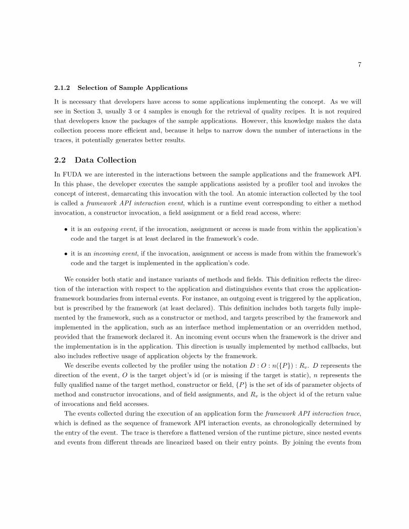
In FUDA we are interested in the interactions between the sample applications and the framework API.In this phase, the developer executes the sample applications assisted by a profiler tool and invokes theconcept of interest, demarcating this invocation with the tool. An atomic interaction collected by the toolis called a framework API interaction event, which is a runtime event corresponding to either a methodinvocation, a constructor invocation, a field assignment or a field read access, where:
• it is an outgoing event, if the invocation, assignment or access is made from within the application’scode and the target is at least declared in the framework’s code.
• it is an incoming event, if the invocation, assignment or access is made from within the framework’scode and the target is implemented in the application’s code.
We consider both static and instance variants of methods and fields. This definition reflects the direc-tion of the interaction with respect to the application and distinguishes events that cross the application-framework boundaries from internal events. For instance, an outgoing event is triggered by the application,but is prescribed by the framework (at least declared). This definition includes both targets fully imple-mented by the framework, such as a constructor or method, and targets prescribed by the framework andimplemented in the application, such as an interface method implementation or an overridden method,provided that the framework declared it. An incoming event occurs when the framework is the driver andthe implementation is in the application. This direction is usually implemented by method callbacks, butalso includes reflective usage of application objects by the framework.
We describe events collected by the profiler using the notation D : O : n({P}) : Rv. D represents thedirection of the event, O is the target object’s id (or is missing if the target is static), n represents thefully qualified name of the target method, constructor or field, {P} is the set of ids of parameter objects ofmethod and constructor invocations, and of field assignments, and Rv is the object id of the return valueof invocations and field accesses.
The events collected during the execution of an application form the framework API interaction trace,which is defined as the sequence of framework API interaction events, as chronologically determined bythe entry of the event. The trace is therefore a flattened version of the runtime picture, since nested eventsand events from different threads are linearized based on their entry points. By joining the events from
8 Framework API Understanding through Dynamic Analysis, Heydarnoori, Tonelli, and Czarnecki
different threads, FUDA is capable of analyzing multi-threaded systems. For example, in the case wheretwo threads cooperate to the execution of a concept, such as an implementation of the Worker Pattern[9],all interactions are merged and analyzed in conjunction. This is possible because FUDA recipes do notpreserve order.
The framework API interaction trace contains a marked region, which is the subsequence of events thatwere marked in the process by the developer, i.e., the ones that started during the concept execution. Forexample, when collecting data on the context menu, we could get a trace with the following events, amongothers, where ~ indicates a marked event:Outgoing:155:
org.eclipse.jface.action.MenuManager.addMenuListener({2456}):~ Outgoing:155:
org.eclipse.jface.action.MenuManager.createContextMenu({}):62412
2.3 Automated Analysis
In this phase, the interaction traces are dissected by an analyzer tool and implementation recipes areextracted. This process involves the following 4 stages:
2.3.1 Concept Trace Slicing
We have seen that the interaction events that occurred during the concept execution are marked by thedeveloper. The marked region therefore contains the events that were explicitly involved in running theconcept, potentially among other irrelevant events. However, the necessary setup for the concept executionfrequently happens well before the execution itself. Likewise, the marked region may miss cleanup events,such as service deregistration.
In order to address this problem we present a novel concept trace slicing technique. The key idea is tointroduce the notion of dependency between events and compute the transitive closure of the events in themarked region. The resulting set of events is defined as the concept slice of the trace.
Two events are said to be dependent if they involve at least one object in common. Objects can takepart in events as targets, parameters or return values. Hence, we can specify fine grained versions ofdependencies, based on how the common object is used in the events. Since events are ordered in thetrace, we can say that events ei and ej have a target−parameter dependency if ei precedes ej in the traceand the same object used as a target in event ei is subsequently used as a parameter in ej . The concepttrace slicing technique can be configured to account for all types of dependencies or for just a subset,depending on the nature of the concept. In order to maximize the reach of the concept trace slicing, inour experiments we have used all types of dependencies in conjunction.
The concept trace slicing technique assumes that all initial events are relevant for the concept. Forthe purposes of FUDA we may safely assume that events in the marked region are relevant, because anyirrelevant event is very likely going to be removed by the subsequent stages of the analysis.

9
The result of this process is a concept slice of the trace, where events that do not by any means dependon an event of the marked region are declared irrelevant and removed from the trace. Within the conceptslice, events have a minimal distance to the marked region. If we create a graph where events representthe vertices and dependencies are the edges, the distance between events is defined as the shortest pathbetween their corresponding vertices. In the concept slice, this is a measure of how far an event is fromthe marked region and can be used to order events in the implementation recipes.
Looking at the example events from Section 2.2 it can be noticed that both use the same target object.Hence, it constitutes a target − target dependency and both events would remain in the resulting trace.Because the second event is in the marked region, its distance is 0. The first event is reachable in one step,thus, it has a distance 1.
2.3.2 Event Abstraction
At this point of the analysis, the sliced traces still contain application specific information. Since the nextsteps will attempt to find similarities between traces, it is necessary to abstract any application specificelements from the events. FUDA translates events into abstract events in 3 steps. First, since object ids arejust relevant to determine dependencies in the concept trace slicing, they are removed from events. Second,parameters of method and constructor invocations are also ignored. The reason is that two methods withthe same name but different number or types of parameters are very likely conceptually equivalent, i.e.,they probably serve the same purpose and just differ in the input data they are working with. Similarly,constructors with different parameters have the same purpose of creating an object and we can assumethat they are equivalent.
The third step deals with the fully qualified name of the event’s target. Independently if the target isa method, a constructor or a field, the fully qualified name of the enclosing class is always present. In thisstep we perform a simple static analysis on the type hierarchy of the target’s enclosing class to find theso called root types of the event and generate an abstract event for each root type. Thus, a single eventmay potentially result in many abstract events. In the following we discuss the abstraction rules for eachtype of target. In order to illustrate the possible cases, we use the example displayed in Figure 1. Theclass diagram is taken from the context menu implementation in JFace, but was extended to assist theexplanation.
Static methods, static fields and instance fields. Fields and static methods cannot be polymor-phically called. However, it is possible to hide the member if a sub-class declares a method or field withthe same name as the super-class. For example, in Figure 1 both ContributionManager and MenuManager
declare the field overrides. Depending on which class is used statically, a different field is really beingused. Therefore, in order to find the exact member in use we search the type hierarchy of the targetbottom-up and we assume the first type that declares the member as the root type.
Constructors. A constructor invocation means that an object of a certain class is going to be created.However, the class can represent many types, both coming from its class inheritance hierarchy and fromthe possible implemented interfaces. Looking bottom-up from the target type, the type hierarchy is a

10 Framework API Understanding through Dynamic Analysis, Heydarnoori, Tonelli, and Czarnecki
Object
+equals()
FWObject
IContributionManager
+isDirty()
MenuManager
+overrides
ContributionManager
+overrides
+isDirty()
IContributionItem
+isDirty()
IMenuManager
AppMenuManager
Framework Types
Language Specific Types
Application Types
IToolBarManager
Figure 1: An example of inheritance hierarchy and the boundaries between application, framework, andlanguage specific types.
directed acyclic graph (DAG), as can be seen in Figure 1 for the class MenuManager. For constructorinvocations, a meaningful abstraction is to generate one root type for each type at the bottom borderlineof the framework of the target type’s inheritance DAG. The rationale is that, both for incoming andoutgoing events, the construction of objects with application types is irrelevant, hence we look for themost specific framework type. The analysis traverses the DAG bottom-up and generates a root typefor the first framework-declared type for each branch. For example, if AppMenuManager is the target,it generates MenuManager and IToolBarManager as root types; if MenuManager is the target, the onlyroot type will be MenuManager itself. Note that another approach could be to generate a root type foreach topmost framework type. While this approach would help agglomerate more events, we would loosethe information of framework variants in use. To exemplify the problem, consider the hierarchy in thefigure, where the framework defines a root class called FWObject. By using this approach, all constructioninvocations would generate an FWObject root type.
Instance Methods. When abstracting instance methods, two factors influence our approach. First,since we are trying to maximize the generalization, we search for the topmost type that declares themethod. This also reflects the fact that the type declaring a method is its conceptual host. For example,the equals method in Java is declared by the Object class. Although there might be many implementationof equals, it conceptually belongs to Object, and it makes sense to aggregate events in this type. Second,since the same method might have multiple topmost types, one root type is generated for the topmost
11
type of each branch. For instance, a method invocation to MenuManager.isDirty would generate rootsfor IContributionManager and IContributionItem, because both interfaces declare the method.
The example events described in Section 2.2 are both outgoing method invocations. The createContextMenuinvocation is just declared by MenuManager. But addMenuListener is in fact declared by IMenuManager.Therefore, those events would yield the following abstract events:Outgoing:
org.eclipse.jface.action.IMenuManager.addMenuListener()
Outgoing:
org.eclipse.jface.action.MenuManager.createContextMenu()
2.3.3 Traces Clustering
It is often possible for applications to implement framework-provided concepts in different ways. Forexample, there are many different ways of implementing a figure in an Eclipse Graphical Editing Framework(GEF1) editor: simple figures are easily handled by pre-defined framework classes, while more complexfigures require more interaction with the API. In order to account for this situation, FUDA employs aclustering technique that groups traces based on a degree of similarity. Applying clustering brings 2 mainbenefits. First, the existence of different clusters of recipes in the result indicates to the developer thatthere are various ways of implementing the concept.
Second, clustering helps removing outliers from the sample. For example, it may happen that thedeveloper incorrectly supposes that an application implements a certain concept. For instance, the conceptof Action in Eclipse can be analyzed by FUDA because actions are triggered by buttons in the graphicaluser interface. If the developer analyzes an application using a button that does not utilize an action, thenthe trace will not contain the concept. By using clustering, this trace would belong to a separate clusterand the developer will be able to identify the mistake.
FUDA’s process is agnostic with respect to the clustering algorithms it can utilize. In general, clusteringis the process of partitioning a set of data items into groups (clusters) such that items within a clusterare more similar to each other than they are similar to items in other clusters. The degree of similaritybetween two items or two clusters is called their distance. There is a variety of algorithms to cluster thedata items and a multitude of distance measures. It is not in the scope of this report to go into theirdetails and the reader is directed to [7] for a thorough discussion. Currently, FUDA utilizes hierarchicalclustering [7], which is appropriate when the number of clusters is determined dynamically.
2.3.4 Recipes Mining
The mining stage takes the traces of abstract events of a cluster and extracts implementation recipes. Tothis end, FUDA uses mining frequent closed itemsets [16] to find abstract events that are common betweentraces. Broadly speaking, this technique is used to look at a set of transactions (traces) containing items
1http://www.eclipse.org/gef/
12 Framework API Understanding through Dynamic Analysis, Heydarnoori, Tonelli, and Czarnecki
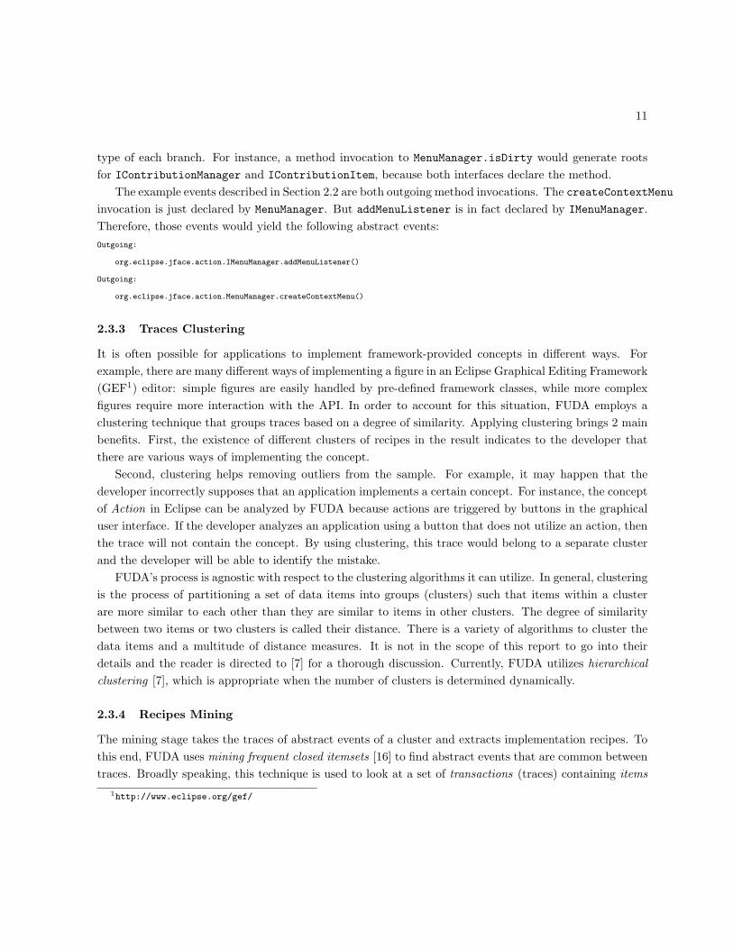
Figure 2: An example implementation recipe generated by FUDA for the concept Context Menu by usingthree sample applications.
(abstract events), and determine the largest sets (recipes) of items that are commonly found in thesetransactions. In this context, largest set means that the technique ignores frequent subsets, since they arepart of another frequent set.
When creating the recipe, an abstract event is transformed into an instruction. Because the distanceto the marked region of the abstract event can be different on each trace, only the minimal distance istaken by the instruction. For example, suppose that the createContextMenu invocation is also found inanother trace, but with distance 2. The generated instruction would have the same format of the abstractevent, but with distance 1, which is their minimum.
The support of an instruction is the percentage of traces that contained its corresponding abstract eventand the support of a recipe is the minimum support between its instructions. The supporting applicationsof a recipe are those applications that generated all instructions contained in the recipe. The result of thisphase is a sequence of recipes in descending order of their support. Besides an indication of its support,a recipe also contains a list of supporting applications and a list of instructions in ascending order oftheir distance to the marked region. For instance, Figure 2 illustrates an example implementation recipegenerated by FUDA for the concept Context Menu when three sample applications are used.
2.4 Results Inspection
The last phase deals with making right use of the recipes. The existence of different clusters of recipesindicates that there are main variants in the implementation of the concept, or eventually that some outlierswere detected. Within a cluster, the developer can locate the best recipe and check its instructions. In

13
general, they indicate the mandatory steps to implement the concept. The distance to the marked regionroughly indicates the steps that separate the instruction from the actual execution of the concept. Forexample, the addMenuListener invocation is one step away from the marked region, which means that,although not directly involved in the execution of the concept, this instruction is directly related to anobject used in the execution. Furthermore, in order to get more details, the developer is handed with alist of the applications where these instructions were detected.
3 Empirical Evaluation
The main objectives of the FUDA approach can be formalized in the following hypothesis:
Hypothesis. FUDA can determine useful implementation recipes with few false positives and falsenegatives by using only a small number of example applications.
In order to verify this hypothesis, we have designed an empirical experiment that provides the followingevidence: i) a quantitative analysis of how the number of sample applications impacts the size and thenumber of false positives and false negatives on the resulting recipes, and ii) a qualitative analysis of theusefulness of the extracted recipes.
Moreover, we have engineered the experiment so that we can also quantitatively analyze the influenceof marking, concept trace slicing and clustering on the results. In the following we describe the toolimplementations and the experiment.
3.1 Tool Support
As described earlier, FUDA prescribes the use of a profiler and an analyzer tool. The former is responsiblefor assisting the developer in collecting and marking traces during data collection, and the latter implementsthe automated analysis phase. We have implemented a profiler tool that instruments applications usingaspects written in AspectJ 2. Developers must only define the framework and application packages, andexecute the instrumented application. The tool also contains a GUI that helps developers to demarcatethe begin and end of a concept’s execution. To instrument code inside the Eclipse platform, the profilertool can be used together with an AJEER3 plug-in.
We have also implemented an analyzer tool in Java. The tool receives application traces stored in files bythe profiler tool, applies the whole process of the automated analysis phase and outputs the implementationrecipes. To conduct mining frequent closed itemsets in clusters of traces of abstract events, we use LCMver. 3.0 (Linear time Closed itemset Miner) [13] that outperforms many of the existing algorithms.
2http://www.aspectj.org/3http://ajeer.sourceforge.net/

14 Framework API Understanding through Dynamic Analysis, Heydarnoori, Tonelli, and Czarnecki
3.2 Setup of the Experiment
The empirical experiment was designed to provide evidence that corroborates the aforementioned hypoth-esis. The experiment was executed in the two following steps.
3.2.1 Data Collection
The first task was to select input data for the experiment, i.e., the frameworks, concepts and applicationsto be analyzed. Table 1 describes the selected concepts, their corresponding framework and their origins.Concepts marked with a * represent the ones we selected from newsgroups. We focused on Eclipse basedframeworks, because they provide a variety of concepts and many open source example applications. Theselected concepts came either from developer questions posted on the frameworks’ newsgroups or camefrom simply looking at the Eclipse workbench and asking how to implement some functionalities present inits plug-ins. The concepts were categorized in two types. Concepts of Type I are questions related only tothe concept’s execution, without worrying about setups and cleanups, in which case it is not necessary toemploy concept trace slicing to augment the marked region. Concepts of Type II are those which requirecomplete information regarding the concept implementation and concept trace slicing is necessary.
For each concept we randomly selected a number of applications of different domains and having differ-ent sizes. The applications came from default Eclipse plug-ins and from the Eclipse Plug-ins Repository4.Each application was instrumented by our profiler tool and executed separately. The invocation of theconcept was demarcated with the assistance of the tool. The result of this step was a number of frameworkAPI interaction traces of the complete execution and containing the marked region for the concepts. Foreach concept at least 6 application traces were collected.
3.2.2 Data Analysis
The collected data was then processed by our analyzer tool to generate implementation recipes. The firstpart of the analysis concerns the evaluation of the impact of the number of applications on the resultingrecipes. To this end, for each concept we randomly selected a single trace and processed it alone. Thenwe subsequently added more randomly selected traces to the analysis and generated the correspondingrecipes. The second part was related to the impact of marking, concept trace slicing and clustering on theresults. In this regard, for each concept we processed 4 random traces considering i) that the completetrace would be the marked region (simulating if marking was not possible), ii) only the marked region(without concept trace slicing), iii) the traditional process with concept trace slicing, and iv) forced theanalysis to use just a single cluster for the concept. In both parts we have just analyzed the first resultingrecipe of each cluster.
In order to evaluate the content of the resulting recipes, we must introduce the notion of mandatoryand optional instructions. An instruction is mandatory for a concept if the realization of the conceptcannot be completed without the instruction. For example, the instructions corresponding to the abstract
4http://www.eclipse-plugins.info

15
Table 1: Concepts selected for the experiment.Concept Framework Description
CONCEPT TYPE I Select* GEFWhat events happen when a user clickson a figure in a GEF editor?
DoubleClick*
GEFWhat events happen when a user doubleclicks inside a GEF editor?
Hover* GEFWhat events happen when a user hoversa figure in a GEF editor?
Focus* JFaceWhat events happen when a user clickson the title-bar of an Eclipse view?
CONCEPT TYPE II Table Viewer EclipseHow to create a typical table viewer inthe Eclipse environment?
Tree Viewer EclipseHow to create a typical tree viewer in theEclipse environment?
Navigation EclipseHow to create the set of Go Home, Go Back
and Go Into actions in the Eclipse treeviewer’s toolbar for navigating trees?
ContextMenu JFaceHow to create a context menu in anEclipse view?
Action JFaceHow to create an action in the toolbar ofan Eclipse view?
Figure* GEFHow to implement drawing a figure in aGEF editor?
Connection GEFHow to implement drawing a connectionbetween two figures in a GEF editor?
Drag-N-Drop*
GEFHow to implement drag and drop into aGEF editor from its palette?
ContentAssist JFaceHow to implement the content assistantfeature in the Eclipse text editors?

16 Framework API Understanding through Dynamic Analysis, Heydarnoori, Tonelli, and Czarnecki
events of Section 2.3.2 are mandatory for the implementation of a context menu because without theseinstructions a context menu does not work. However, a context menu can optionally contain a separatorand, thus, the corresponding instruction is optional.
Besides mandatory and optional instructions, a recipe may also contain instructions that are notrelevant to the implementation of the concept. Such instructions are called the false positives of a recipe.The instructions that are mandatory for a concept but that are not included in a recipe are called therecipe’s false negatives.
The determination of the set of mandatory instructions for the realization of a concept, as well asof which instructions can be declared optional, requires a reference. For some concepts the availabledocumentation served as a guide. Independently of documentation availability, the authors manuallyinspected sample applications code to come up with the set of mandatory instructions. Also, an instructionwas declared optional based on the authors understanding of the concept. This knowledge acquired whilestudying the extracted recipes, the available documentation and the sample application’s code was theinput for the last step, the qualitative analysis.
3.3 Results
3.3.1 Quantitative Analysis
Figure 3 presents the results of the first part of the quantitative analysis. It displays the impact of thenumber of sample applications on the recipe. For brevity and because we have collected very similar resultsfor all concepts in the experiment, we just present the results for 4 concepts here.
The diagrams display only the number of false positives and the size of the resulting recipes. Thenumber of false negatives is omitted because in all cases it was 0, i.e., it was always possible to detectall mandatory instructions, even when increasing the number of applications. Still, as can be seen in thediagrams, by slightly increasing the number of applications the recipes become smaller and with fewer falsepositives. After the number of applications is increased to 3 or 4, the quality of the recipe tends to stabilize,with the number of false positives approaching 0. This shows that by using only a few applications it ispossible to obtain recipes that get closer to the set of mandatory instructions.
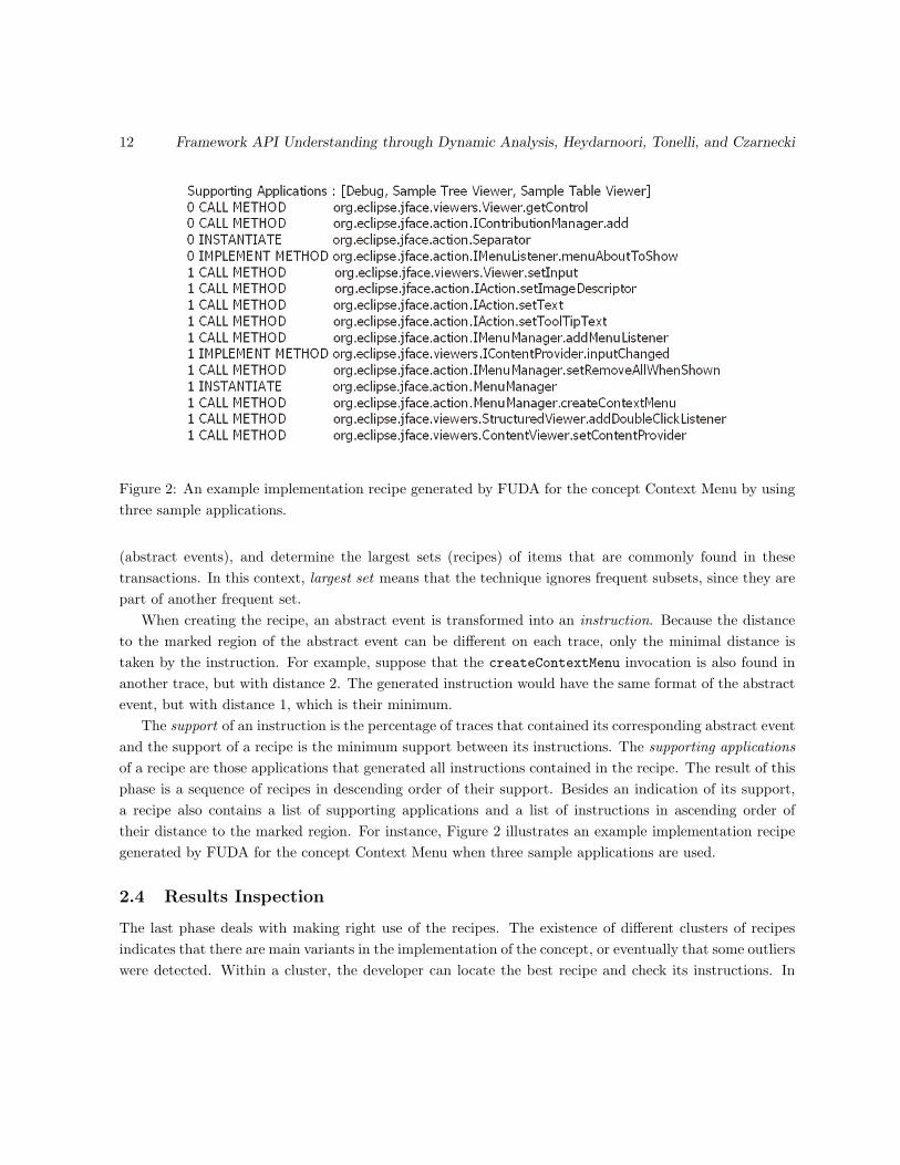
The results of the second part are presented in Table 2. In this Table, Complete Trace shows thesimulation of not having marking, when the whole trace in considered the marked region; Just MarkedRegion represents the processing of just the marked region, without slicing; and With Concept Trace Slicingdisplays the results when the concept trace slicing technique is in use. Furthermore, S, P, and N are thesize, number of false positives and negatives, respectively. The column S displays not only the size, butalso the number of mandatory and optional instructions found in the recipe, in this order. The conceptswhose recipes ended up in different clusters have one row for each cluster. Concepts marked with a *represent the ones without available documentation, in which case the set of mandatory instructions isdetermined only by code inspection. All results correspond to the use of 4 random applications to extractthe recipe.
17
Table 2: Quality of recipe extracted with 4 sample applications for the concepts introduced in Table 1.
Concept
Complete Just Marked With Concept
Trace Region Trace Slicing
S P N S P N S P N
Select*54(3)(4)
47 03(3)(0)
0 0 - - -
DoubleClick*
62(2)(3)
57 02(2)(0)
0 0 - - -
Hover*
52(0)(0)
52 44(4)(0)
0 0 - - -
52(0)(0)
52 11(1)(0)
0 0 - - -
Focus20(1)(0)
19 01(1)(0)
0 0 - - -
Table Viewer27(13)(14)
0 027(13)(14)
0 027(13)(14)
0 0
Tree Viewer31(13)(18)
0 031(13)(18)
0 031(13)(18)
0 0
Navigation*23(9)(7)
7 07(3)(4)
0 619(9)(7)
3 0
ContextMenu15(6)(6)
3 03(2)(1)
0 415(6)(6)
3 0
Action15(2)(2)
11 01(1)(0)
0 15(2)(2)
1 0
Figure
63(16)(33)
14 023(12)(11)
0 456(16)(33)
7 0
68(16)(34)
18 024(12)(12)
0 455(16)(32)
7 0
Connection57(23)(19)
15 022(14)(8)
0 944(23)(18)
3 0
Drag-N-Drop53(20)(20)
13 018(12)(6)
0 840(20)(19)
1 0
ContentAssist18(2)(11)
5 01(0)(0)
1 216(2)(11)
3 0

18 Framework API Understanding through Dynamic Analysis, Heydarnoori, Tonelli, and Czarnecki
0
10
20
30
40
50
60
70
80
90
1 2 3 4 5 6
Number of Example Applications
Recipe Size
Number of FalsePositives
0
10
20
30
40
50
60
70
80
90
100
1 2 3 4 5 6
Number of Example Applications
Recipe Size
Number of FalsePositives
(a) Context Menu (b) Tree Viewer
0
10
20
30
40
50
60
70
80
90
1 2 3 4 5 6
Number of Example Applications
Recipe Size
Number of FalsePositives
0
10
20
30
40
50
60
70
80
90
100
1 2 3 4 5 6
Number of Example Applications
Recipe Size
Number of FalsePositives
(c) Connection (d) Action
Figure 3: Impact of the number of sample applications on the recipe size and number of false positives.
The results for the Complete Trace column indicate that using the whole application trace is insufficientfor getting quality recipes, because, although those recipes contain few false negatives, they are very largeand present many false positives. We can understand the impact of marking at runtime by comparing theresults of this column with Just Marked Region. For all concepts, the size of the recipes and the number offalse positives are drastically reduced. For concepts of Type I, whose target is solely the concept execution,the recipes are perfect, in the sense that they contain all mandatory instructions and no optionals. However,because the marked region can miss setup and cleanup interactions, using only the marked region eventsto retrieve complete recipes yields many false negatives for concepts of Type II.
The impact of the concept trace slicing technique is observable by comparing column With ConceptTrace Slicing with the previous results. Because the technique selectively augments the marked region, itis able to reach all relevant events without bringing many irrelevant ones. In this way, it extracts recipeswithout false negatives and that are in general much smaller and with fewer false positives if comparedwith the complete trace. The only exception is the Context Menu, where the results were very similar tothe complete trace. By analyzing this case closely, we realized that the selected sample applications haveonly this concept in common, a situation that eliminated false positives from the analysis of the completetrace. Note that concepts of Type I don’t require concept slicing and are left outside this analysis.
The impact of clustering can be measured by forcing the analysis to use just a single cluster for eachconcept. The only concepts affected are those that presented clusters in the first place, Hover and Figure.The results of forcing a single cluster in their analysis is presented in Table 3. For Hover, using the

19
Table 3: Impact of not performing clustering on the quantitative results.
Concept
Complete Just Marked With Concept
Trace Region Trace Slicing
S P N S P N S P N
Hover 52 524
4 0 0 - - -
(0)(0) 1 (4)(0)
Figure51(16)(22)
13 020(12)(8)
0 439(16)(20)
3 0
complete trace generates a recipe that only contains false positives. The reason is because the sampleapplications have many instructions in common that are not implementing the concept. The two rows offalse negatives indicates the situation for each of the recipes generated with clusters. If just the markedregion is used, then the process extracts a complete and useful recipe. However, it represents only oneof the two possible variants discovered with clustering. This result is similar to the ones obtained forFigure. For this concept, the resulting recipes had quality relatively comparable to the ones obtained withclustering. Yet, one implementation variant was missing.
3.3.2 Qualitative Analysis
To perform the qualitative analysis of the recipes generated by the FUDA, they were compared against thedocumentation of the frameworks, actual example application’ source code and their enclosing comments,and the responses to the questions in the developers newsgroups. Using this analysis, we were able tovalidate our evaluation hypothesis that it is possible to determine useful implementation recipes by usinga few example applications. In particular, we were able to answer some questions to which there wereno answer in the newsgroups; find some errors in some of the responses; or find recipes which are morecomplete than what is provided in the documentation of the frameworks under the study.
For the concept Select, the response in the newsgroup is: “it looks like handleMousePressed is called”.Nevertheless, when we searched all the example plug-ins in the GEF package and example plug-ins from theInternet, none of them had this method in their source code. However, by applying the FUDA technique onjust the marked regions of traces, it was easily possible to understand that those example applications callmethod createDeleteCommand when a figure is selected in a GEF editor. For the concept Double Click,when just marked regions of traces were used, the recipe found by FUDA was exactly the same as theresponse in the GEF developers newsgroup. For the concepts Hover, Focus, and Drag-N-Drop there wereno answers to those questions in the forum. However, with the help of the FUDA technique, we were ableto find the answers to those questions. Then, we checked our recipes against the source code of exampleapplications and existing documentation and confirmed that the generated recipes are true. In particular,for the concept Drag-N-Drop, we found that Outgoing EditPartViewer.addDragSourceListener and
20 Framework API Understanding through Dynamic Analysis, Heydarnoori, Tonelli, and Czarnecki
Outgoing EditPartViewer.addDropTargetListener are relevant instructions to the concept Drag-N-Drop which are not discussed in the GEF Programmer’s Guide in the Eclipse environment. For thisconcept, the only false positive in the recipe when concept trace slicing is performed was Outgoing
EditPartViewer.setContextMenu which is easily identifiable by the software engineer.For the concepts Context Menu and Action, the false positives were those that manipulate the Eclipse
view itself such as Outgoing ContentViewer.setContentProvider. The reason is that a context menuis invoked or an action is run inside an Eclipse view, and therefore the false positive instructions thatmanipulate the Eclipse view show themselves in the recipes.
For the concepts Figure and Connection, all the false positives when concept trace slicing is performedare those instructions that manipulate the palette of the GEF editor. The reason is that in order to drawa figure or create a connection in a GEF editor, we had to select them from the its palette in all of ourexample applications and therefore the instructions that were related to the implementation of palettewere included in the recipes. If the software engineer is interested in those instructions as well, then theycan be removed from the set of false positives.
When complete traces are used for the concepts in GEF, many of the false positives are those thatinitialize the GEF editor itself such as creating the action bar and creating the palette and its entries.
3.3.3 Tool Performance
All experiments were executed on a Pentium IV 1.60GHz machine with 1.00 GB of RAM. The requiredtime for processing the framework API interaction traces and extracting the implementation recipes variedbetween 2 and 3 seconds. However, the time for collecting the traces depended on the size and usualperformance of the example applications and frameworks, and on the target concept. In our experiments,recording each framework API interaction trace took up to 5 minutes.
3.4 Threats to Validity
This section discusses the threats to validity of the evaluation results presented in the preceding sections.We distinguish between internal validity in which potential threats in executing the steps of the experimen-tal study are discussed, from external validity which relates to what extent the results can be generalized[8].
Internal Validity. The main threat to internal validity is related to manually counting the number offalse positives and false negatives. Manual inspection is typically subject to errors. However, to computethe number of false positives, it was easily possible to identify the relevance of a given instruction usingdocumentation and/or program source code. Furthermore, since the size of the recipes were often succinct,it was easily possible for the authors to check the correctness of number of false positives in several iterationsto minimize this threat.
Regarding the number of false negatives, it is difficult to guarantee their correctness because of somesort of context dependency in the definition of a concept, i.e., it depends on users’ point of view of a concept;

21
particularly when a concept includes variable elements. To minimize this threat, in our experiments, wefocused only on well-defined concepts in frameworks documentation or newsgroups. Moreover, the authorsput great care while defining the set of mandatory instructions for a target concept.
Another threat to internal validity relates to the incompleteness of frameworks documentation we usedto compute the number of false positives and false negatives. To minimize this threat, we not only usedthe documentation provided by the frameworks developers, but also we used a number of articles availableover the Internet. Furthermore, we used example applications source code as the complement of thosedocumentation.
Finally, there might be some problems in the prototype implementation of FUDA that can lead to wrongconclusions. To minimize this threat, the authors of this report independently debugged the profiler andanalyzer tools. However, there might be still some issues with the instrumentation of applications andframeworks. For instance, AspectJ which we used for the purpose of instrumentation can not instrumentstatic strings since they are in-lined with the code. Nevertheless, there are a number of predefined staticstrings in the GEF framework to which different requests from the applications to the framework arecompared. Using our prototype implementation of FUDA, we were not able to capture those strings.
External Validity. Our experimental evaluation involves three inputs: frameworks, concepts, andexample applications. The way in which instances were selected for these variables directly affects theexternal validity of the results.
Frameworks. One threat to external validity is that all the frameworks in our experimental study areGUI frameworks in the Eclipse environment. Therefore, the experimented frameworks are not represen-tative of different types of frameworks in practise. In particular, frameworks that use reflection such asStruts5 and Spring6 are quite common nowadays. Nevertheless, we did not perform experimental studywith these frameworks and left it for our future work.
Concepts. One major threat to external validity is that the experimented concepts are all GUI concepts,self-contained, and very easy to delineate during invocation. This threat was minimized by selecting themost common concepts in the experimented frameworks, and referring to newsgroups to answer realprogramming issues. Nonetheless, another threat to external validity is that the selected questions fromthe forums are not representative. To minimize this threat, we randomly selected the questions from thepool of questions we extracted from newsgroups.
Example Applications. The selection of example applications for each concept and the order of pro-cessing them directly affects the results since the number of false positives and false negatives are highlydependent on how the desired concept is implemented in those applications. To reduce the risk of thisthreat and obtain results that can be generalized, we not only used example applications that were pro-vided by the framework developers, but also we used example applications available in open source softwarerepositories in the Internet. Furthermore, for each concept, at each step of the experiment, we randomlyselected the example applications from the pool of sample applications.
5http://struts.apache.org/6http://www.springframework.org/

22 Framework API Understanding through Dynamic Analysis, Heydarnoori, Tonelli, and Czarnecki
4 Discussion
4.1 Strengths and Weaknesses
The empirical evaluation results indicate that FUDA can retrieve useful recipes from only few sampleapplications. Furthermore, the approach is highly automated and scalable. The processing of the traces isfully automatic and the instrumentation does not impose significant overhead on the application executionsince only the API interaction rather than full traces are recorded. Given a set of applications andscenarios, the amount of time needed to retrieve recipes is mainly determined by the amount it takes toexecute the scenarios on the applications. Furthermore, dynamic analysis will detect what API elementsare actually being invoked. This is important since frameworks typically use polymorphism and reflectionand the presence of these languages renders static analysis less applicable. Finally, using the currentimplementation of FUDA, it is possible to profile closed source Java applications as well. This propertymakes FUDA applicable even if the sources of the sample applications are not available.
Nevertheless, the approach has some potential drawbacks. Most importantly, the quality of the re-sults may depend on the selection of the applications. Thus, creating the scenarios might require somecareful design to isolate the API instructions of interest in the context of composite concepts. We com-ment on this issue in the next subsection. Second, all dynamic approaches are dependent on the inputdata and generalizing from this data might not be safe. In that sense, FUDA will retrieve the set ofAPI instructions that are invoked in each execution, but may fail to retrieve optional API instructions.Finally, dynamic approaches require the setup of the runtime environment, which might not be easy insome situations. Therefore, being able to retrieve useful recipes from only few application executions isparticularly important.
4.2 Scenario Design Considerations
The nature of the concept and the ways in which it is implemented by the applications can influencethe results. Ideally, the concept is self-contained, its invocation is easily delimitable, and the sampleapplications have only this concept in common. If this is the case, FUDA will bring most benefits.In general, concepts are composites of other concepts, the invocation of a concept might not be easilydemarcated, and the sample applications have many concepts in common. For example, most pluginsimplementing context menus also implement actions, views and other Eclipse concepts. In this case, it iseven more crucial that developers can demarcate the boundaries of the concept execution. Furthermore,some concepts usually come always associated with other concepts and, as it turns out, it is very difficultto separate them. For example, in order to open a popup menu in an Eclipse view, something must beselected. It is therefore hard to describe the concept of popup menu without the concept of selection.

23
4.3 Concept Trace Slicing
It is worth noting that the dynamic concept trace slicing presented in Section 2.3.1 is quite different fromtraditional dynamic program slicing [2]. First, while program slicing is defined in terms of data and controldependencies, concept trace slicing is defined in terms of relevance relationships between API invocationsthat incurred by the use of common objects as targets, parameters, or return values. Furthermore, whiletraditional dynamic slicing is defined with respect to a trace containing all program instructions that wereexecuted, dynamic concept mining operates on API interaction traces.
The dependency relationship is motivated by common API usage patterns. For example, two methodinvocations sharing the same target objects could be related by the fact that one invocation initializesthe target for the second invocation, or the second invocation cleans up the object that was used in thefirst one. Similarly, an invocation that returns an object that is later used as a target or parameter in asubsequent invocation may be an invocation to a factory method. Clearly, our relevance relationship maylead both to false positives and false negatives. For example, false positives commonly occur if the sameobject is used in two invocations for unrelated uses. False negatives can happen if invocations are relatedby side effects, such as accessing some objects in some framework registry. Nevertheless, as shown in theempirical evaluations, many of the false positives would be sorted out of the recipes in the data miningstage, and situations leading to false negatives are uncommon in the first place.
As the final point, one may question why the dependencies between two events in a framework APIinteraction trace are defined using the objects that are involved in those events instead of the actual datadependencies between the events, similarly to traditional slicing techniques. To answer this question,we defined the relevancy between two events using their data dependencies and performed the empiricalevaluations for a number of concepts in Table 1. In all the experiments, it turned out that the completeframework API interaction traces were automatically marked since the API events were densely connectedby data dependencies. As a result, many false positives were present in the resulting recipes, and wedecided to use the object dependencies approach.
5 Related Work
Framework Usage Comprehension. Several tools for mining framework usage patterns from sampleapplications exist. Examples include XSnippet [12], Strathcona [6], Prospector [10], MAPO [15], CodeWeb[11], and FrUiT [3]. Both XSnippet and Strathcona are context-sensitive code assistant tools that allowdevelopers to query a repository of code snippets that are relevant to the programming task at hand.Prospector is a tool that accepts queries in the form of a pair (τin, τout) where τin and τout are class types.A query returns code snippets that instantiate an object of type τout from a given input object type τin.MAPO is a tool that searches open source repositories by using a query that characterizes an API by amethod, class, or package. Then, it applies data mining techniques to mine closed sequential patterns frommethod call sequences extracted from the source files. CodeWeb [11] applies data mining on the source

24 Framework API Understanding through Dynamic Analysis, Heydarnoori, Tonelli, and Czarnecki
code of programming libraries or frameworks to discover reuse patterns in existing applications. FrUiTuses the association rules mining technique to extract common framework usage patterns from existingframework applications and keep them in a database. Then, application developers can automaticallyquery those patterns that are relevant in the context of their current task.
A recent work done by Acharya et al. [1] uses a frequent partial order mining tool to mine partialorders in program traces that are statically generated for APIs of interest by using a model checker tool.All these tools mentioned before use static analysis and are mainly code assistants in the context of aprogramming task at hand, such as how to call a specific framework method or how to instantiate aparticular framework class. Therefore, these tools are mostly helpful when the developer at least knowsthe API element of interest and they are less helpful if the developer has only a high level idea of theconcept that needs to be implemented. In contrast, FUDA uses primarily dynamic analysis in order toallow the developer to identify the concept of interest by invoking it explicitly. As a result, the developerdoes not need any knowledge of the framework API other than the names of the packages in which itresides.
Concept Location. Understanding how a certain concept or functionality is implemented in thesource code of an application is an important program comprehension problem that is often referred toas the concept location or feature location. The concept location techniques can be mainly classified intostatic, such as SNIAFL [17], dynamic, such as Software Reconnaissance [14], and hybrid ones, such asthe approach based on concept analysis [4], which combine static and dynamic analysis. To the best ofour knowledge, none of these techniques explicitly address the issue of concept location in the context offramework comprehension. Nevertheless, the approach based on concept analysis is worth discussing inmore detail as it is highly related to FUDA. The key idea of the approach is to execute a set of scenarios—each exhibiting one or more features—to obtain execution traces and then to use concept analysis to locatethe relevant units in the application code. In essence, the approach locates the features by computing allintersections and unions of the traces. The located units become starting points for user-assisted staticanalysis to locate additional feature-relevant units, e.g., object creation and clean-up instructions. Thereare several significant differences between this approach and FUDA. (i) Most importantly, the approach isnot focused on API usage and the resulting feature slices will contain many application-specific instructionsthat are irrelevant from the viewpoint of framework usage. FUDA avoids this problem by focusing on APIinteraction traces. (ii) Furthermore, the approach works with traces from a single application, while FUDAenables the use of different applications through API event abstraction. The use of different applicationsaffords more diversity in the traces and can lead to better results with fewer traces. In some cases, usingdifferent applications may even be the only way to obtain any useful results. For example, obtainingtraces that use an Eclipse tree view in different ways from one application may not be possible. (iii)Another difference is that concept invocations are marked in FUDA. This marking avoids the need fora non-invoking trace to mask irrelevant events in the concept invoking trace. (iv) Finally, FUDA usesdynamic concept trace slicing instead of user-assisted static analysis. Static analysis for object-orientedprograms is often highly imprecise due to polymorphism and reflection.

25
6 Conclusion and Future Work
The API of many modern object-oriented software frameworks is large and complex. Hence, novice ap-plication developers often require a great amount of time and effort to learn how to use it. This reportpresented FUDA, a new approach that combines a novel dynamic slicing approach with clustering and datamining techniques to comprehend the implementation recipes of a framework-provided concept. A recipespecifies the API instructions that are commonly involved in the implementation of a concept. Our exper-imental results show that FUDA can generate the implementation recipes for a given framework-providedconcept with just few false positives and false negatives by using only a few different sample applicationsimplementing that concept.
Suggestions for future work include augmenting the recipes with additional information extracted fromthe traces, such as call nesting, partial ordering of calls, and object passing patterns. Furthermore, a simplepostprocessing of the recipes could provide more detail about the instructions, such as listing whether acall back was provided by implementing an interface or overriding framework-provided class. User studiesare necessary to determine which of these extensions should be provided first and how the informationshould be presented.
References
[1] M. Acharya, T. Xie, J. Pei, and J. Xu. Mining API patterns as partial orders from source code: Fromusage scenarios to specifications. In ESEC/FSE, New York, NY, USA, September 2007. ACM Press.
[2] H. Agrawal and J. R. Horgan. Dynamic program slicing. In PLDI, pages 246–256, New York, NY,USA, 1990. ACM Press.
[3] M. Bruch, T. Schafer, and M. Mezini. FrUiT: IDE support for framework understanding. In eTX,pages 55–59, New York, NY, USA, 2006. ACM Press.
[4] T. Eisenbarth, R. Koschke, and D. Simon. Locating features in source code. IEEE TSE, 29(3):210–224,2003.
[5] E. Gamma and K. Beck. Contributing to Eclipse: Principles, Patterns, and Plugins. Addison-Wesley,2003.
[6] R. Holmes and G. C. Murphy. Using structural context to recommend source code examples. InICSE, pages 117–125, 2005.
[7] A. K. Jain, M. N. Murty, and P. J. Flynn. Data clustering: A review. ACM Computing Survey,31(3):264–323, 1999.
26 Framework API Understanding through Dynamic Analysis, Heydarnoori, Tonelli, and Czarnecki
[8] B. A. Kitchenham, S. L. Pfleeger, L. M. Pickard, P. W. Jones, D. C. Hoaglin, K. E. Emam, andJ. Rosenberg. Preliminary guidelines for empirical research in software engineering. IEEE TSE,28(8):721–734, 2002.
[9] D. Lea. Concurrent Programming in Java Design Principles and Patterns. Addison-Wesley, 1996.
[10] D. Mandelin, L. Xu, R. Bod́ık, and D. Kimelman. Jungloid mining: helping to navigate the APIjungle. In PLDI, pages 48–61, New York, NY, USA, 2005. ACM Press.
[11] A. Michail. Data mining library reuse patterns using generalized association rules. In ICSE, pages167–176, New York, NY, USA, 2000. ACM Press.
[12] N. Sahavechaphan and K. Claypool. XSnippet: Mining for sample code. In OOPSLA, pages 413–430,New York, NY, USA, 2006. ACM Press.
[13] T. Uno, M. Kiyomi, and H. Arimura. LCM ver.3: Collaboration of array, bitmap and prefix tree forfrequent itemset mining. In OSDM, pages 77–86, New York, NY, USA, 2005. ACM Press.
[14] N. Wilde and M. C. Scully. Software reconnaissance: Mapping program features to code. Journal ofSoftware Maintenance, 7(1):49–62, 1995.
[15] T. Xie and J. Pei. MAPO: Mining API usages from open source repositories. In MSR, pages 54–57,New York, NY, USA, 2006. ACM Press.
[16] M. J. Zaki. Mining non-redundant association rules. Data Mining Knowledge Discovery, 9(3):223–248,2004.
[17] W. Zhao, L. Zhang, Y. Liu, J. Sun, and F. Yang. SNIAFL: Towards a static noninteractive approachto feature location. ACM TOSEM, 15(2):195–226, 2006.