Composites Design Page 1 Composites Design -...
162
Composites Design Preface Using This Guide More Information What's New? Getting Started Entering the Composites Design Workbench Defining the Composites Parameters User Tasks Creating Preliminary Design Defining a Zones Group Defining a Zone Defining a Transition Zone Running the Connection Generator Creating an ITP Creating a Solid From Zones Importing Importing a Laminate Creating Plies Creating a Stack-up File From Zones Defining a Plies Group Creating Plies From Zones Creating Plies Manually Creating a Core Creating a Stack-Up File From Plies Creating a Limit Contour Exploding Plies Analyzing Launching the Numerical Analysis Creating a Core Sampling Creating Manufacturing Process Creating a Manufacturing Document Swapping the Skin Defining the EOP Defining the EEOP Defining the MEOP Defining the Material Excess Analyzing the Producibility Flattening Exporting Data 1 Page Composites Design Version 5 Release 13
-
Upload
truongxuyen -
Category
Documents
-
view
223 -
download
1
Transcript of Composites Design Page 1 Composites Design -...
Composites Design
Preface
Using This Guide More Information
What's New?
Getting Started
Entering the Composites Design Workbench Defining the Composites Parameters
User Tasks
Creating Preliminary Design Defining a Zones Group Defining a Zone Defining a Transition Zone Running the Connection Generator Creating an ITP Creating a Solid From Zones
Importing Importing a Laminate
Creating Plies Creating a Stack-up File From Zones Defining a Plies Group Creating Plies From Zones Creating Plies Manually Creating a Core Creating a Stack-Up File From Plies Creating a Limit Contour Exploding Plies
Analyzing Launching the Numerical Analysis Creating a Core Sampling
Creating Manufacturing Process Creating a Manufacturing Document Swapping the Skin Defining the EOP
Defining the EEOP Defining the MEOP
Defining the Material Excess Analyzing the Producibility Flattening
Exporting Data
1Page Composites Design Version 5 Release 13
Exporting Ply Data Removing Ply Shells Interoperability With Wireframe
Creating Points Creating Lines Creating Planes Creating Circles
Interoperability With Generative Shape Design Joining Surfaces or Curves
Interoperability With Drafting
Composites Interoperability
Optimal CATIA PLM Usability for Composites Design
Workbench Description
Menu Bar Parameters Toolbar Preliminary Design Toolbar Import Laminate Toolbar Plies Toolbar Analysis Toolbar Manufacturing Toolbar Data Export Toolbar Wireframe Toolbar GSD Toolbar Specification Tree
Index
2Page Composites Design Version 5 Release 13
PrefaceCATIA Composites Design 3 (CPD) is an advanced composites process centric solution that allows manufacturers, from aerospace to automotive or consumer goods companies, to reduce the time needed to design composites parts.
It delivers tools to cover both the preliminary and detailed design phases while taking into account, even at the concept stage, the product's requirements for finite element analysis and manufacturability.
CATIA Composites Design 3 uniquely delivers a powerful composites design solution with all the advantages of the CATIA V5 architecture: native integration, pervasive knowledgeware capabilities, and CATIA V5 ease of use.
Using This GuideMore Information
3Page Composites Design Version 5 Release 13

Using This GuideThis guide is intended for both Engineering and Manufacturing people.The user should be familiar with basic Version 5 concepts such as document windows, standard and view toolbars.
4Page Composites Design Version 5 Release 13

More InformationPrior to reading this book, we recommend that you read the Infrastructure User Guide.
Conventions
5Page Composites Design Version 5 Release 13
What's New?
New Functionalities
Creating a Limit ContourExploding PliesRemoving Ply ShellsOptimal CATIA PLM Usability for Composites Design
Enhanced Functionalities
Launching the Numerical AnalysisYou can export the analysis in an external file
Creating Manufacturing DataThe manufacturing ply geometry is now generated in a separate .CATPart
Analyzing the ProducibilityParameters of the analysis are now stored under the plyMulti-selection of plies is possibleNew Minimum Distortion and Symmetric options are available
FlatteningMulti-selection of plies is possibleA new Rotate option allows flattening shapes using different parameters
Exporting Ply DataMulti-selection of plies is possibleYou can create a file per ply or per materialYou can export the strategy point and/or the rosette
Integration With DraftingThe Project 3D wireframe option must be activated to be able to visualize the ply contoursPly contours are now represented when generating the .CATDrawing
6Page Composites Design Version 5 Release 13
Getting StartedThe following tutorial aims at guiding you when you open the CATIA Composites Design workbench for the first time.It provides 3 step-by-step tasks for:
Entering the Composites Design WorkbenchDefining the Composites Parameters
This tutorial should take about 5 minutes to complete.
7Page Composites Design Version 5 Release 13
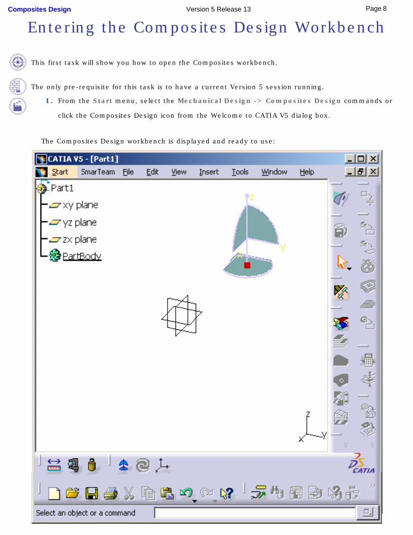
Entering the Composites Design Workbench
This first task will show you how to open the Composites workbench.
The only pre-requisite for this task is to have a current Version 5 session running.
1. From the Start menu, select the Mechanical Design -> Composites Design commands or
click the Composites Design icon from the Welcome to CATIA V5 dialog box.
The Composites Design workbench is displayed and ready to use:
8Page Composites Design Version 5 Release 13

You may add the Composites Design workbench to your Favorites, using the Tools -> Customize item. For more information, refer to the Infrastructure User's Guide.
If you wish to use the whole screen space for the geometry, remove the specification tree clicking off the View -> Specifications Visible menu item or pressing F3.
Now let's perform the next task to learn how to define the Composites Parameters.
9Page Composites Design Version 5 Release 13
Defining the Composites Parameters
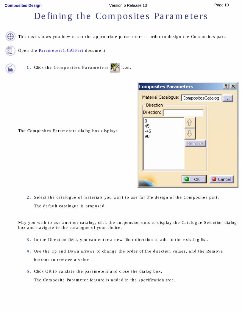
This task shows you how to set the appropriate parameters in order to design the Composites part.
Open the Parameters1.CATPart document
1. Click the Composites Parameters icon.
The Composites Parameters dialog box displays.
2. Select the catalogue of materials you want to use for the design of the Composites part.
The default catalogue is proposed.
May you wish to use another catalog, click the suspension dots to display the Catalogue Selection dialog box and navigate to the catalogue of your choice.
3. In the Direction field, you can enter a new fiber direction to add to the existing list.
4. Use the Up and Down arrows to change the order of the direction values, and the Remove
buttons to remove a value.
5. Click OK to validate the parameters and close the dialog box.
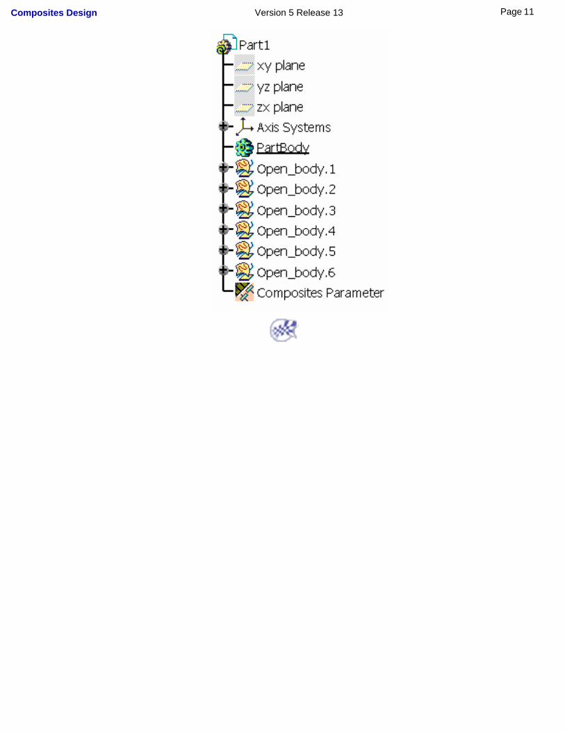
The Composite Parameter feature is added in the specification tree.
10Page Composites Design Version 5 Release 13
11Page Composites Design Version 5 Release 13

User TasksCreating Preliminary Design
ImportingCreating Plies
AnalyzingCreating Manufacturing Process
Exporting DataRemoving Ply Shells
Interoperability With WireframeInteroperability With Generative Shape Design
Interoperability With Drafting
12Page Composites Design Version 5 Release 13

Creating Preliminary DesignDefining a Zones Group
Defining a ZoneDefining a Transition Zone
Running the Connection GeneratorCreating an ITP
Creating a Solid From Zones
13Page Composites Design Version 5 Release 13
Defining a Zones Group
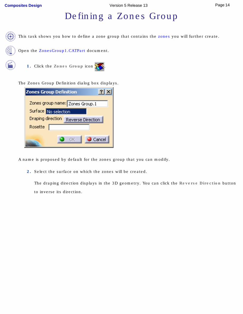
This task shows you how to define a zone group that contains the zones you will further create.
Open the ZonesGroup1.CATPart document.
1. Click the Zones Group icon .
The Zones Group Definition dialog box displays.
A name is proposed by default for the zones group that you can modify.
2. Select the surface on which the zones will be created.
The draping direction displays in the 3D geometry. You can click the Reverse Direction button
to inverse its direction.
14Page Composites Design Version 5 Release 13
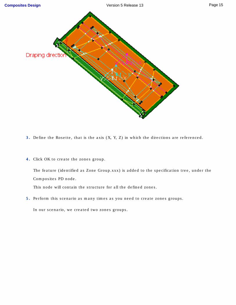
3. Define the Rosette, that is the axis (X, Y, Z) in which the directions are referenced.
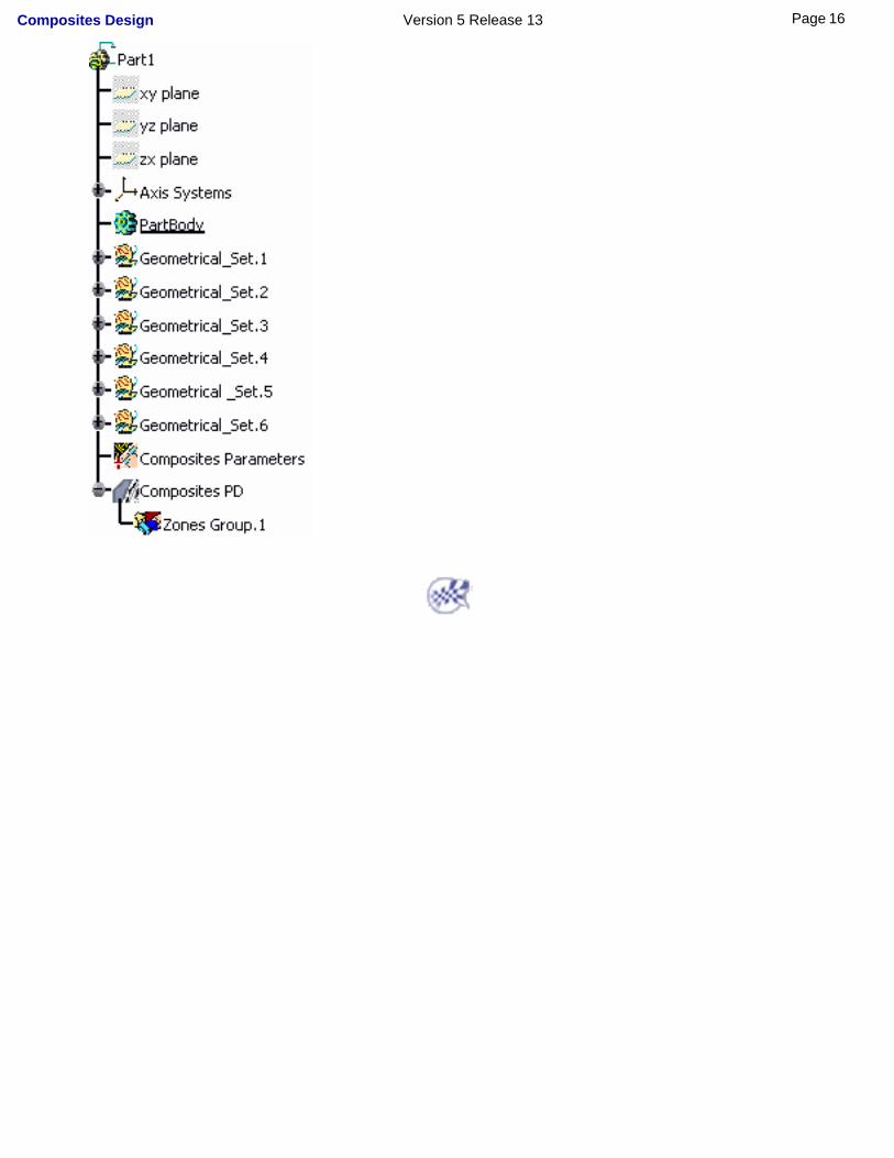
4. Click OK to create the zones group.
The feature (identified as Zone Group.xxx) is added to the specification tree, under the
Composites PD node.
This node will contain the structure for all the defined zones.
5. Perform this scenario as many times as you need to create zones groups.
In our scenario, we created two zones groups.
15Page Composites Design Version 5 Release 13
16Page Composites Design Version 5 Release 13
Defining a Zone
This task shows you how to create a geometrical area defined by a geometry, a constant laminate and a rosette.
● Geometry
● Laminate
● Rosette
Open the ZoneCreation1.CATPart document.
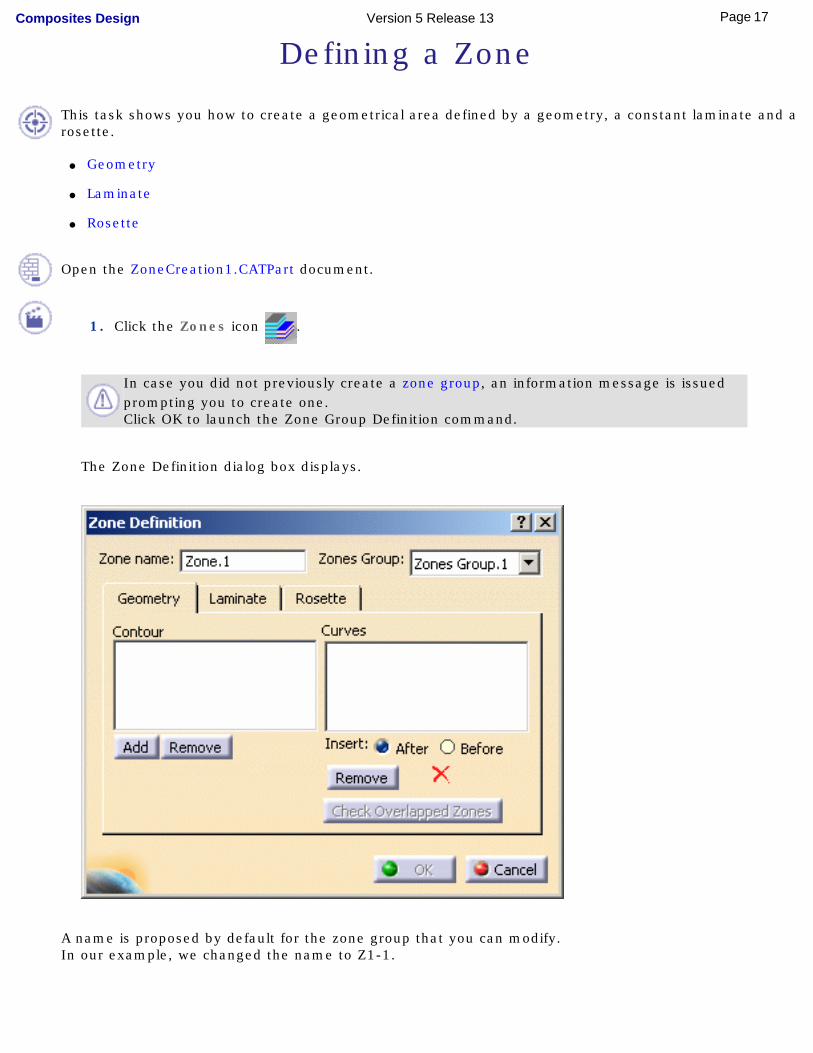
1. Click the Zones icon .
In case you did not previously create a zone group, an information message is issued prompting you to create one.Click OK to launch the Zone Group Definition command.
The Zone Definition dialog box displays.
A name is proposed by default for the zone group that you can modify.In our example, we changed the name to Z1-1.
17Page Composites Design Version 5 Release 13
2. Select the Zones Group to contain the zone.
GeometryThe Geometry tab lets you define a contour in the zone.
A zone can contain several contours.
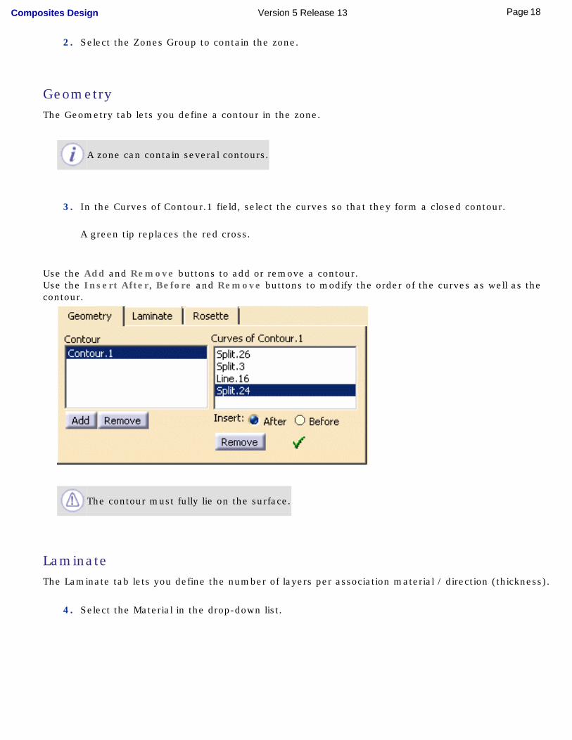
3. In the Curves of Contour.1 field, select the curves so that they form a closed contour.
A green tip replaces the red cross.
Use the Add and Remove buttons to add or remove a contour.Use the Insert After, Before and Remove buttons to modify the order of the curves as well as the contour.
The contour must fully lie on the surface.
LaminateThe Laminate tab lets you define the number of layers per association material / direction (thickness).
4. Select the Material in the drop-down list.
18Page Composites Design Version 5 Release 13
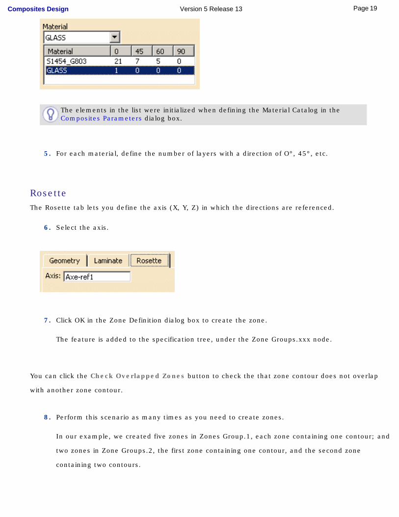
The elements in the list were initialized when defining the Material Catalog in the Composites Parameters dialog box.
5. For each material, define the number of layers with a direction of O°, 45°, etc.
RosetteThe Rosette tab lets you define the axis (X, Y, Z) in which the directions are referenced.
6. Select the axis.
7. Click OK in the Zone Definition dialog box to create the zone.
The feature is added to the specification tree, under the Zone Groups.xxx node.
You can click the Check Overlapped Zones button to check the that zone contour does not overlap
with another zone contour.
8. Perform this scenario as many times as you need to create zones.
In our example, we created five zones in Zones Group.1, each zone containing one contour; and
two zones in Zone Groups.2, the first zone containing one contour, and the second zone
containing two contours.
19Page Composites Design Version 5 Release 13
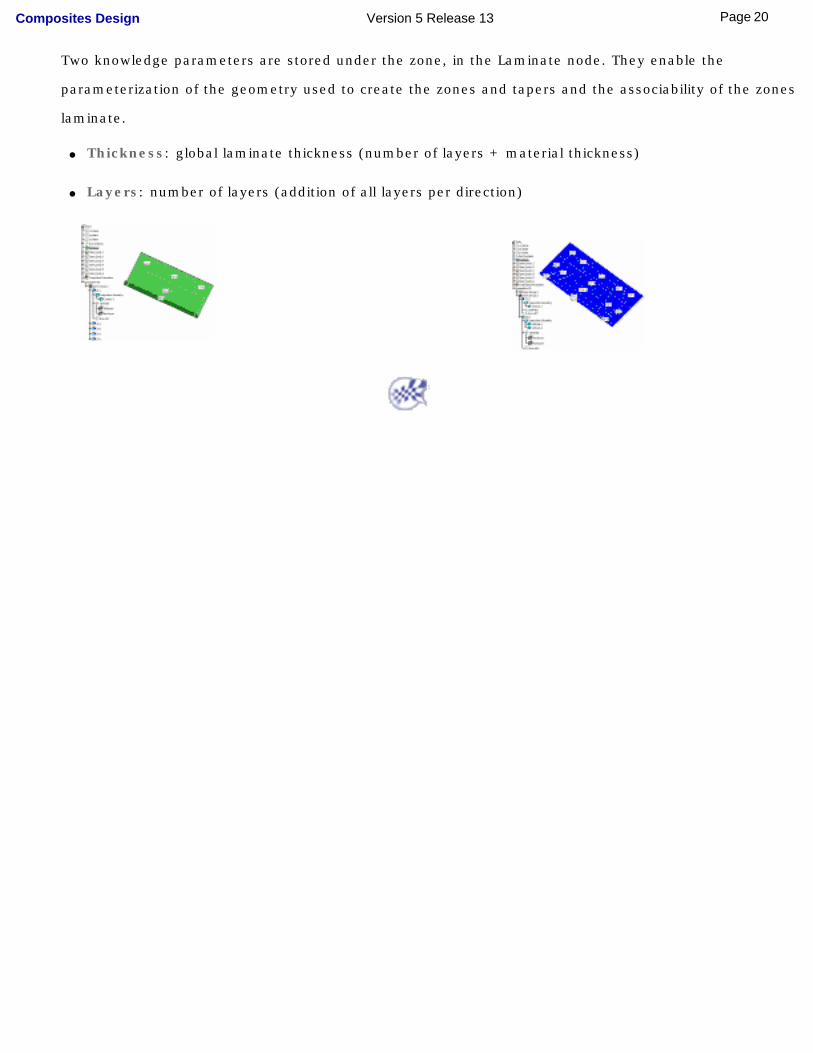
Two knowledge parameters are stored under the zone, in the Laminate node. They enable the
parameterization of the geometry used to create the zones and tapers and the associability of the zones
laminate.
● Thickness: global laminate thickness (number of layers + material thickness)
● Layers: number of layers (addition of all layers per direction)
20Page Composites Design Version 5 Release 13
Defining a Transition Zone
This task shows how to create a transition zone defining the geometric area of the ply drop-off between two zones.
Open the TransitionZone1.CATPart document.
1. Click the Transition Zone icon .
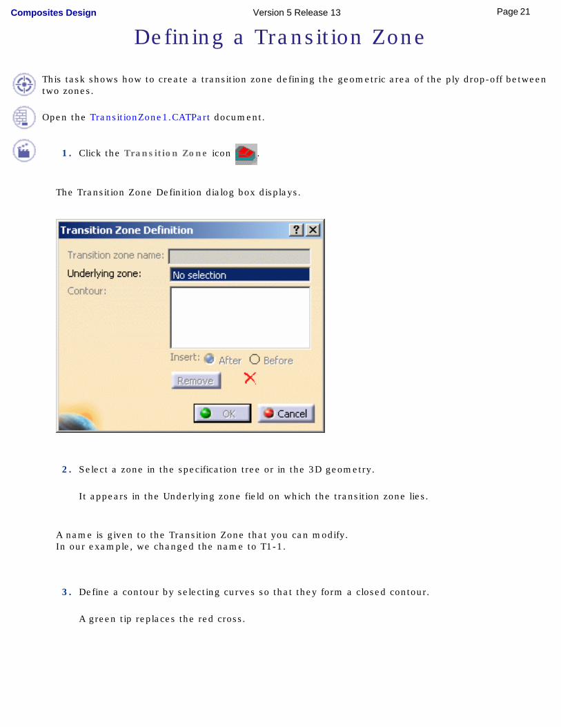
The Transition Zone Definition dialog box displays.
2. Select a zone in the specification tree or in the 3D geometry.
It appears in the Underlying zone field on which the transition zone lies.
A name is given to the Transition Zone that you can modify.In our example, we changed the name to T1-1.
3. Define a contour by selecting curves so that they form a closed contour.
A green tip replaces the red cross.
21Page Composites Design Version 5 Release 13
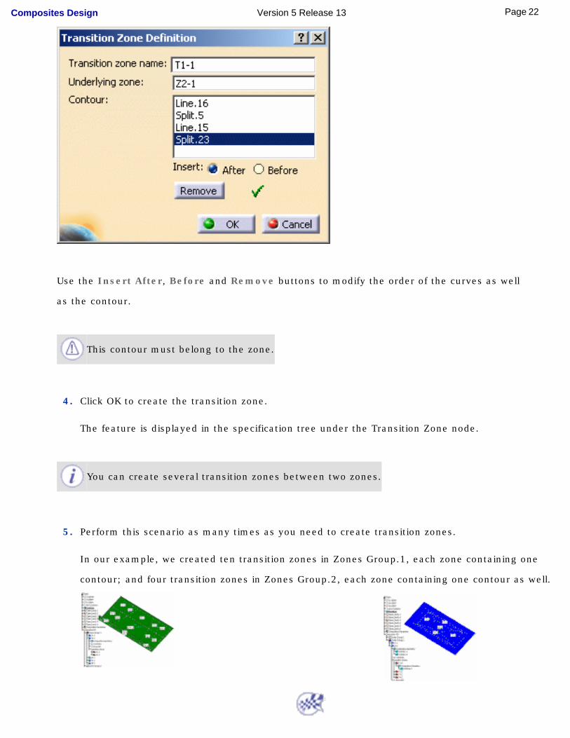
Use the Insert After, Before and Remove buttons to modify the order of the curves as well
as the contour.
This contour must belong to the zone.
4. Click OK to create the transition zone.
The feature is displayed in the specification tree under the Transition Zone node.
You can create several transition zones between two zones.
5. Perform this scenario as many times as you need to create transition zones.
In our example, we created ten transition zones in Zones Group.1, each zone containing one
contour; and four transition zones in Zones Group.2, each zone containing one contour as well.
22Page Composites Design Version 5 Release 13
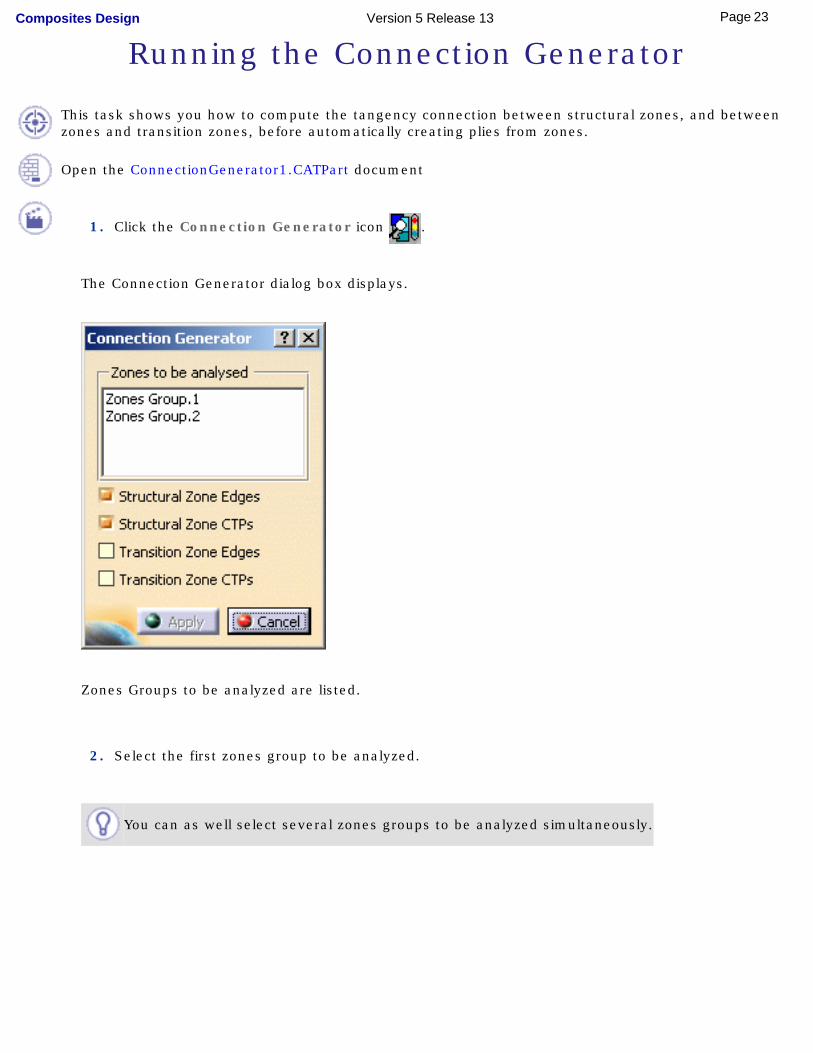
Running the Connection Generator
This task shows you how to compute the tangency connection between structural zones, and between zones and transition zones, before automatically creating plies from zones.
Open the ConnectionGenerator1.CATPart document
1. Click the Connection Generator icon .
The Connection Generator dialog box displays.
Zones Groups to be analyzed are listed.
2. Select the first zones group to be analyzed.
You can as well select several zones groups to be analyzed simultaneously.
23Page Composites Design Version 5 Release 13
3. Check the options of your choice to:
● compute structural zone edges
● compute structural zone thickness points (CTP: Constant Thickness Point)
● compute transition zone edges
● compute transition zone thickness points (CTP)
4. Click Apply to launch the analysis.
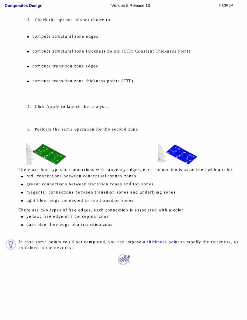
5. Perform the same operation for the second zone.
There are four types of connections with tangency edges, each connection is associated with a color:● red: connections between conceptual connex zones
● green: connections between transition zones and top zones
● magenta: connections between transition zones and underlying zones
● light blue: edge connected to two transition zones
There are two types of free edges, each connection is associated with a color:● yellow: free edge of a conceptual zone
● dark blue: free edge of a transition zone
In case some points could not computed, you can impose a thickness point to modify the thickness, as explained in the next task.
24Page Composites Design Version 5 Release 13
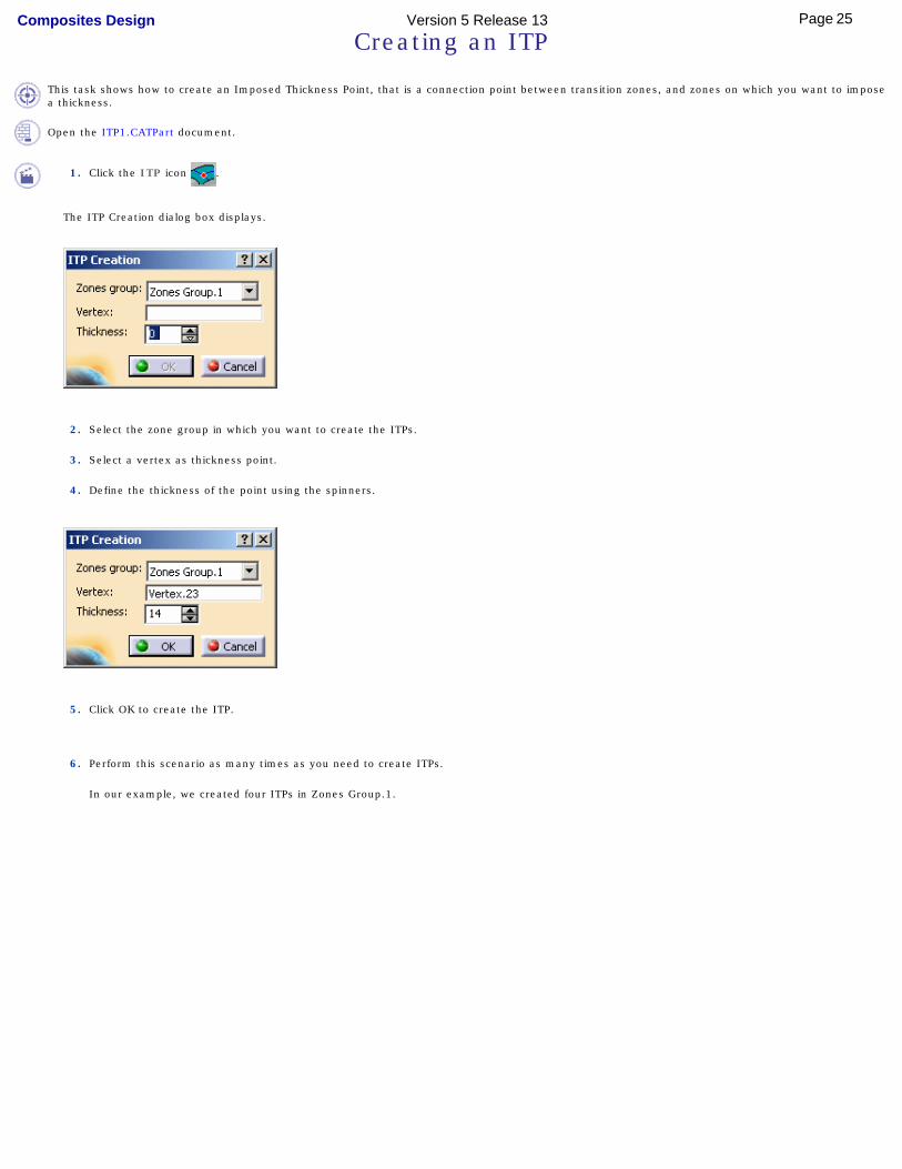
Creating an ITP
This task shows how to create an Imposed Thickness Point, that is a connection point between transition zones, and zones on which you want to impose a thickness.
Open the ITP1.CATPart document.
1. Click the ITP icon .
The ITP Creation dialog box displays.
2. Select the zone group in which you want to create the ITPs.
3. Select a vertex as thickness point.
4. Define the thickness of the point using the spinners.
5. Click OK to create the ITP.
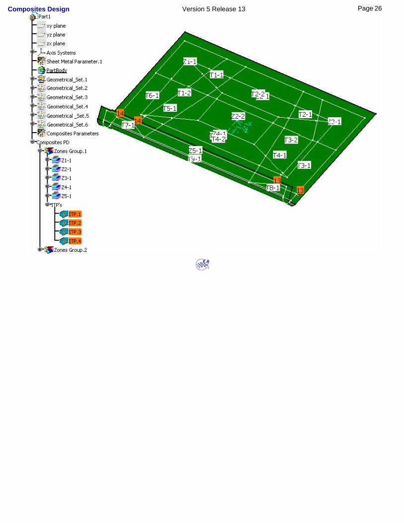
6. Perform this scenario as many times as you need to create ITPs.
In our example, we created four ITPs in Zones Group.1.
25Page Composites Design Version 5 Release 13
26Page Composites Design Version 5 Release 13
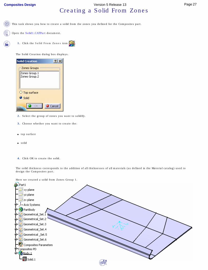
Creating a Solid From Zones
This task shows you how to create a solid from the zones you defined for the Composites part.
Open the Solid1.CATPart document.
1. Click the Solid From Zones icon .
The Solid Creation dialog box displays.
2. Select the group of zones you want to solidify.
3. Choose whether you want to create the:
● top surface
● solid
4. Click OK to create the solid.
The solid thickness corresponds to the addition of all thicknesses of all materials (as defined in the Material catalog) used to design the Composites part.
Here we created a solid from Zones Group 1.
27Page Composites Design Version 5 Release 13

ImportingImporting a Laminate
28Page Composites Design Version 5 Release 13
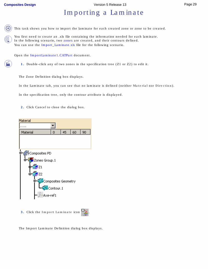
Importing a Laminate
This task shows you how to import the laminate for each created zone or zone to be created.
You first need to create an .xls file containing the information needed for each laminate.In the following scenario, two zones are created, and their contours defined.You can use the Import_Laminate.xls file for the following scenario.
Open the ImportLaminate1.CATPart document.
1. Double-click any of two zones in the specification tree (Z1 or Z2) to edit it.
The Zone Definition dialog box displays.
In the Laminate tab, you can see that no laminate is defined (neither Material nor Direction).
In the specification tree, only the contour attribute is displayed.
2. Click Cancel to close the dialog box.
3. Click the Import Laminate icon .
The Import Laminate Definition dialog box displays.
29Page Composites Design Version 5 Release 13
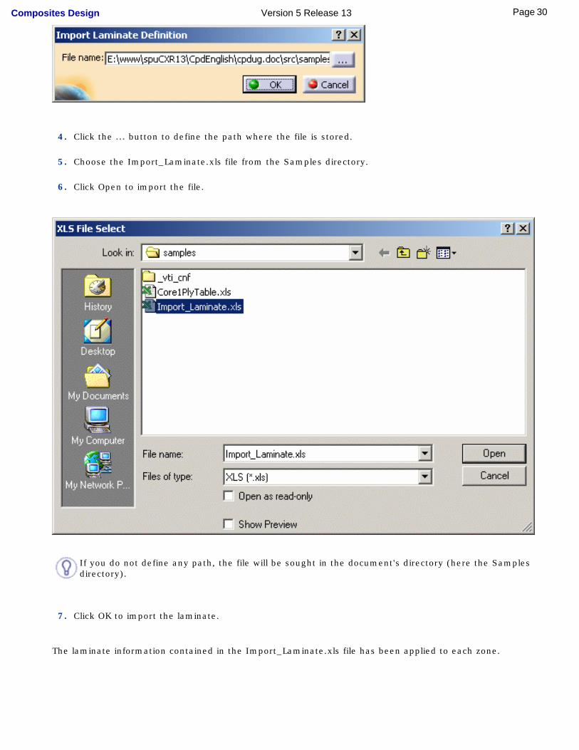
4. Click the ... button to define the path where the file is stored.
5. Choose the Import_Laminate.xls file from the Samples directory.
6. Click Open to import the file.
If you do not define any path, the file will be sought in the document's directory (here the Samples directory).
7. Click OK to import the laminate.
The laminate information contained in the Import_Laminate.xls file has been applied to each zone.
30Page Composites Design Version 5 Release 13
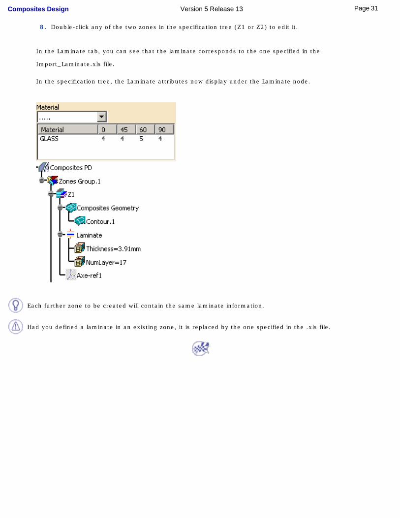
8. Double-click any of the two zones in the specification tree (Z1 or Z2) to edit it.
In the Laminate tab, you can see that the laminate corresponds to the one specified in the
Import_Laminate.xls file.
In the specification tree, the Laminate attributes now display under the Laminate node.
Each further zone to be created will contain the same laminate information.
Had you defined a laminate in an existing zone, it is replaced by the one specified in the .xls file.
31Page Composites Design Version 5 Release 13

Creating PliesCreating a Stack-up File From Zones
Defining a Plies GroupCreating Plies From Zones
Creating Plies ManuallyCreating a Core
Creating a Stack-Up File From PliesCreating a Limit Contour
Exploding Plies
[
32Page Composites Design Version 5 Release 13
Creating a Stack-up File From Zones
This task shows you how to create a stack-up file before creating the plies.It contains the stacking order of the Composites part.
This step is not mandatory. May you be satisfied with the proposed stack-up, you can directly create the plies.
Open the Stack-UpFile1.CATPart document.
1. Click the Plies From Zones icon .
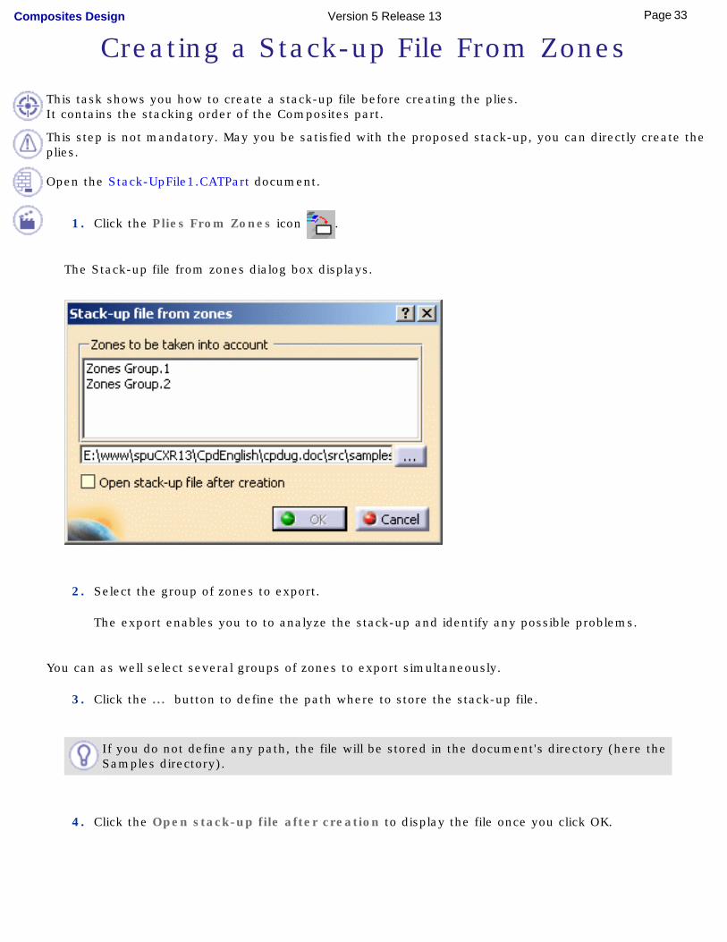
The Stack-up file from zones dialog box displays.
2. Select the group of zones to export.
The export enables you to to analyze the stack-up and identify any possible problems.
You can as well select several groups of zones to export simultaneously.
3. Click the ... button to define the path where to store the stack-up file.
If you do not define any path, the file will be stored in the document's directory (here the Samples directory).
4. Click the Open stack-up file after creation to display the file once you click OK.
33Page Composites Design Version 5 Release 13
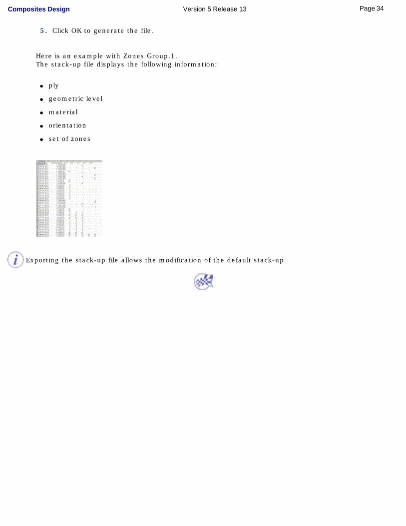
5. Click OK to generate the file.
Here is an example with Zones Group.1.The stack-up file displays the following information:
● ply
● geometric level
● material
● orientation
● set of zones
Exporting the stack-up file allows the modification of the default stack-up.
34Page Composites Design Version 5 Release 13
Defining a Plies Group
This task shows you how to define a plies group that contains the plies you will further create.
Open the PliesGroupCreation1.CATPart document.
1. Click the Plies Group icon .
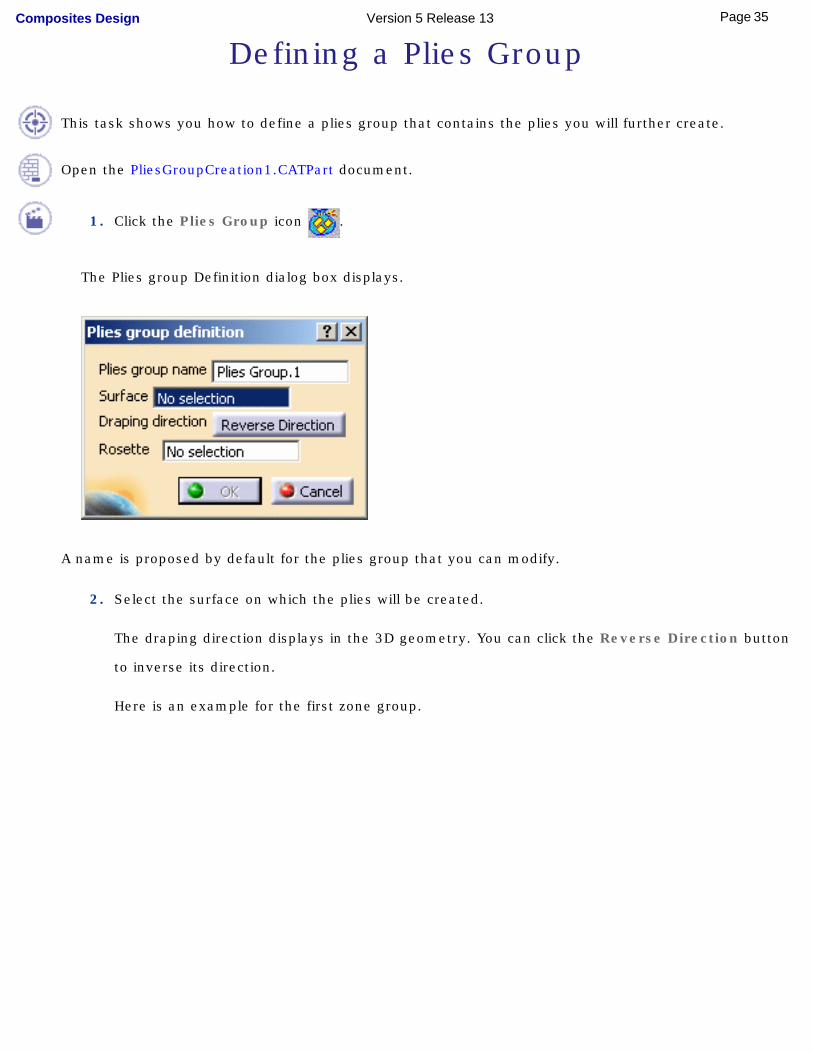
The Plies group Definition dialog box displays.
A name is proposed by default for the plies group that you can modify.
2. Select the surface on which the plies will be created.
The draping direction displays in the 3D geometry. You can click the Reverse Direction button
to inverse its direction.
Here is an example for the first zone group.
35Page Composites Design Version 5 Release 13
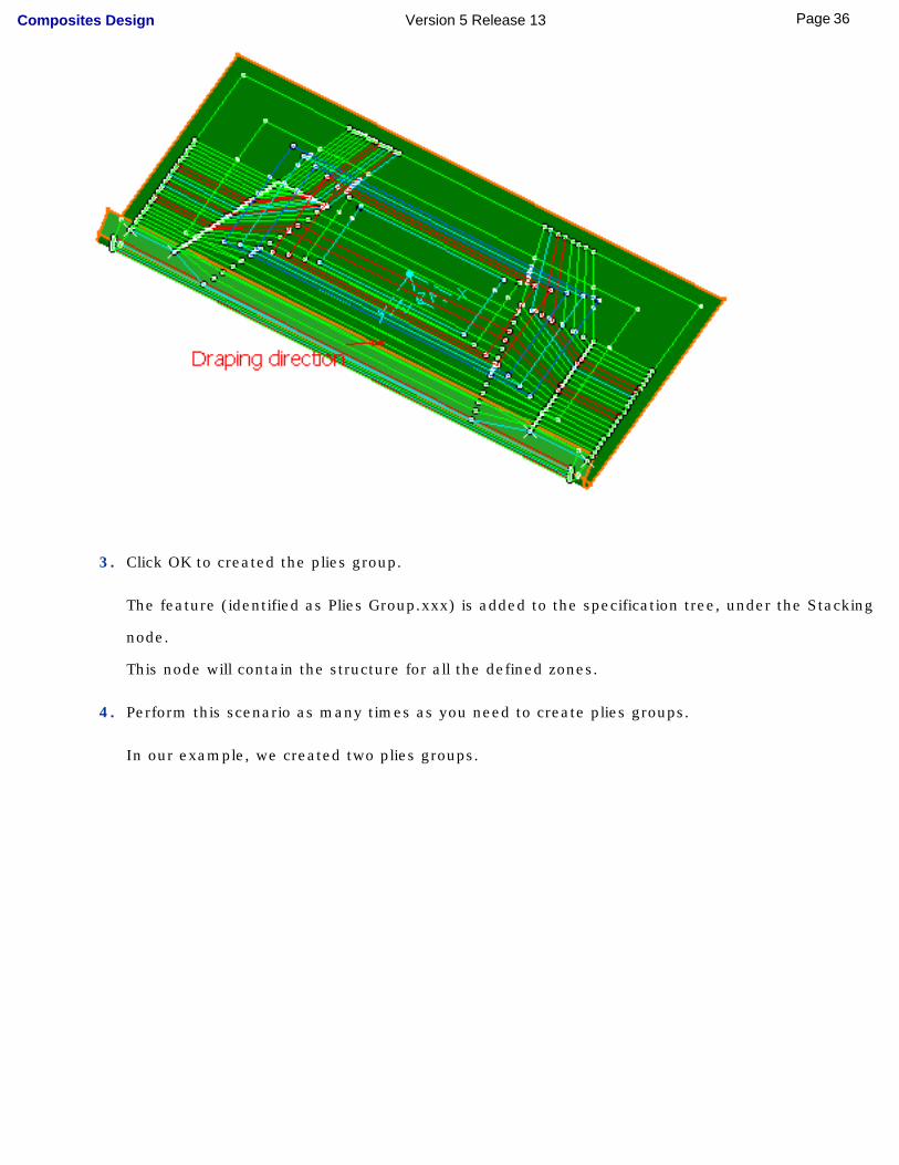
3. Click OK to created the plies group.
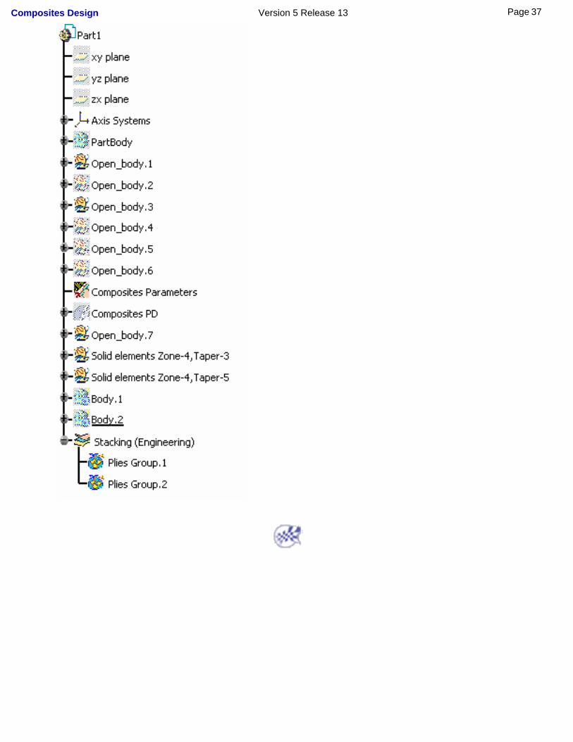
The feature (identified as Plies Group.xxx) is added to the specification tree, under the Stacking
node.
This node will contain the structure for all the defined zones.
4. Perform this scenario as many times as you need to create plies groups.
In our example, we created two plies groups.
36Page Composites Design Version 5 Release 13
37Page Composites Design Version 5 Release 13
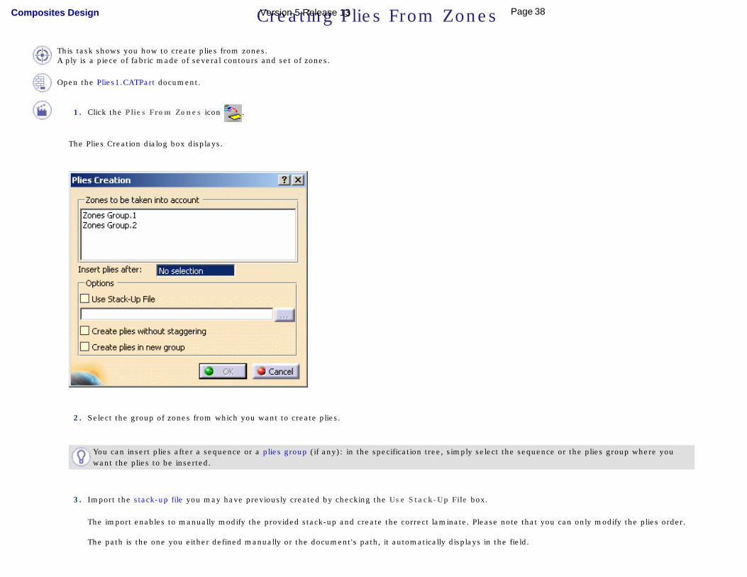
Creating Plies From Zones
This task shows you how to create plies from zones.A ply is a piece of fabric made of several contours and set of zones.
Open the Plies1.CATPart document.
1. Click the Plies From Zones icon .
The Plies Creation dialog box displays.
2. Select the group of zones from which you want to create plies.
You can insert plies after a sequence or a plies group (if any): in the specification tree, simply select the sequence or the plies group where you want the plies to be inserted.
3. Import the stack-up file you may have previously created by checking the Use Stack-Up File box.
The import enables to manually modify the provided stack-up and create the correct laminate. Please note that you can only modify the plies order.
The path is the one you either defined manually or the document's path, it automatically displays in the field.
38Page Composites Design Version 5 Release 13
Importing the stack-up file allows the modification of the default stack-up.
● You can check the Create Plies without staggering box to create plies without staggered geometry.Otherwise, plies will be created with a staggered geometry.
● You can check the Create plies in new group to create the plies in a new plies group.
4. Click OK to create the plies.
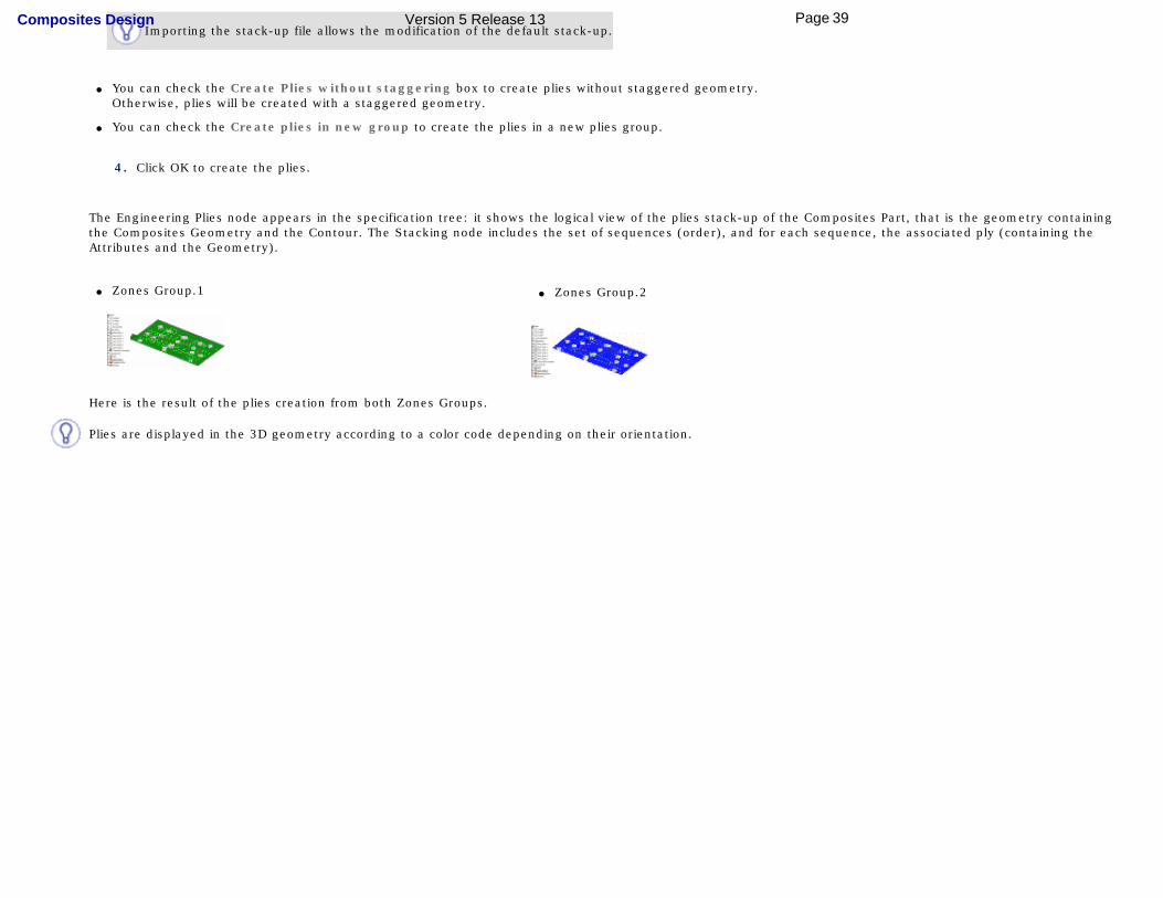
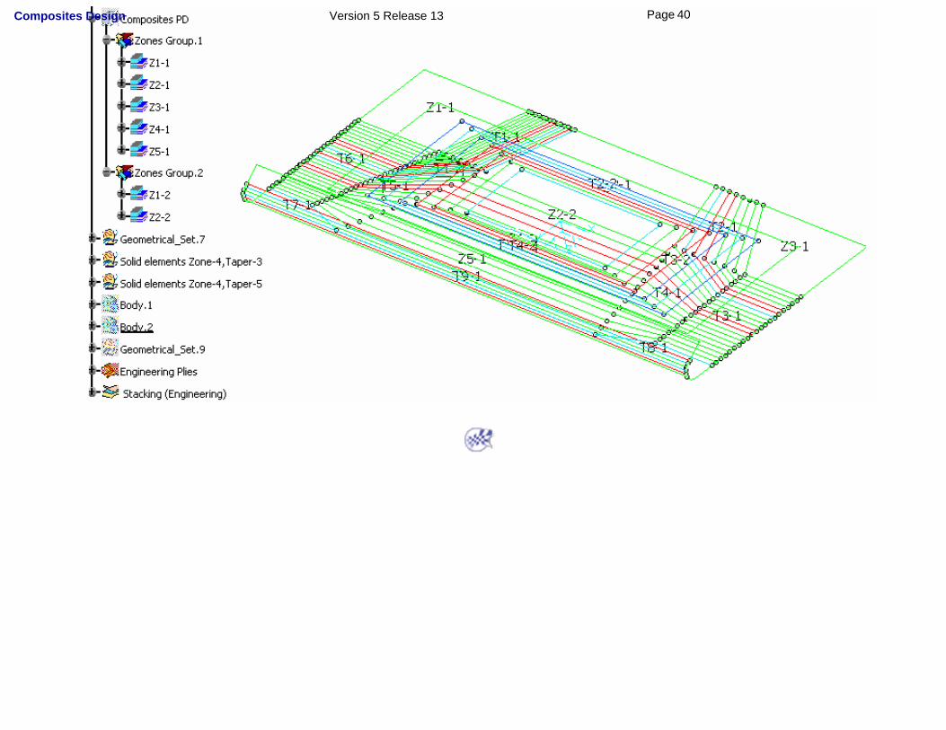
The Engineering Plies node appears in the specification tree: it shows the logical view of the plies stack-up of the Composites Part, that is the geometry containing the Composites Geometry and the Contour. The Stacking node includes the set of sequences (order), and for each sequence, the associated ply (containing the Attributes and the Geometry).
● Zones Group.1 ● Zones Group.2
Here is the result of the plies creation from both Zones Groups.
Plies are displayed in the 3D geometry according to a color code depending on their orientation.
39Page Composites Design Version 5 Release 13
40Page Composites Design Version 5 Release 13
Creating Plies Manually
This task shows you how to manually create plies.A ply is a piece of fabric made of several contours and zones.
Open the Plies1.CATPart document.
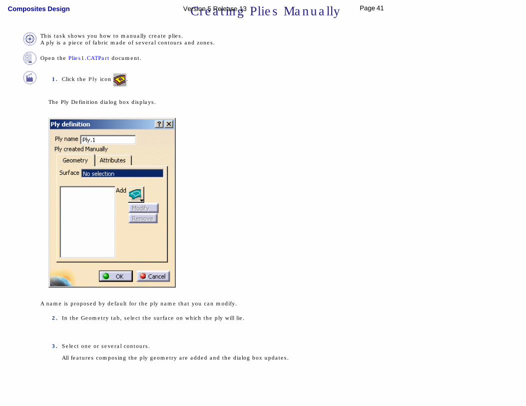
1. Click the Ply icon .
The Ply Definition dialog box displays.
A name is proposed by default for the ply name that you can modify.
2. In the Geometry tab, select the surface on which the ply will lie.
3. Select one or several contours.
All features composing the ply geometry are added and the dialog box updates.
41Page Composites Design Version 5 Release 13
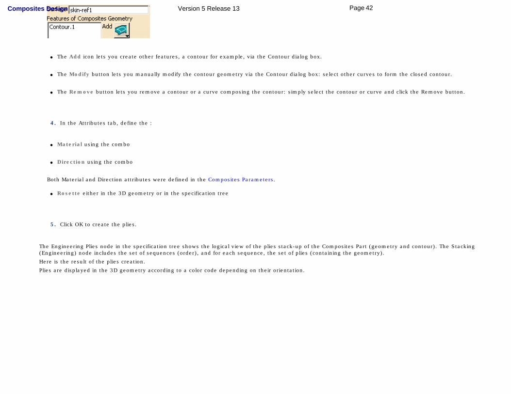
● The Add icon lets you create other features, a contour for example, via the Contour dialog box.
● The Modify button lets you manually modify the contour geometry via the Contour dialog box: select other curves to form the closed contour.
● The Remove button lets you remove a contour or a curve composing the contour: simply select the contour or curve and click the Remove button.
4. In the Attributes tab, define the :
● Material using the combo
● Direction using the combo
Both Material and Direction attributes were defined in the Composites Parameters.
● Rosette either in the 3D geometry or in the specification tree
5. Click OK to create the plies.
The Engineering Plies node in the specification tree shows the logical view of the plies stack-up of the Composites Part (geometry and contour). The Stacking (Engineering) node includes the set of sequences (order), and for each sequence, the set of plies (containing the geometry).
Here is the result of the plies creation.
Plies are displayed in the 3D geometry according to a color code depending on their orientation.
42Page Composites Design Version 5 Release 13
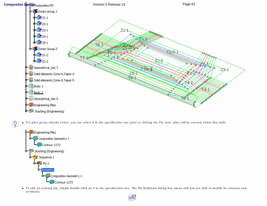
● If a plies group already exists, you can select it in the specification tree prior to clicking the Ply icon: plies will be created within this node.
● To edit an existing ply, simply double-click on it in the specification tree. The Ply Definition dialog box opens and you are able to modify its contours and
attributes.
43Page Composites Design Version 5 Release 13
Creating a Core
This task shows how to create a core, that is an insert enabling you to stiffen the part.
Open the Core1.CATPart document.
1. Select the feature where you want to place the insert.
It can be a ply, a sequence, a plies group or a stacking.
In our example we selected PliesGroup.1.
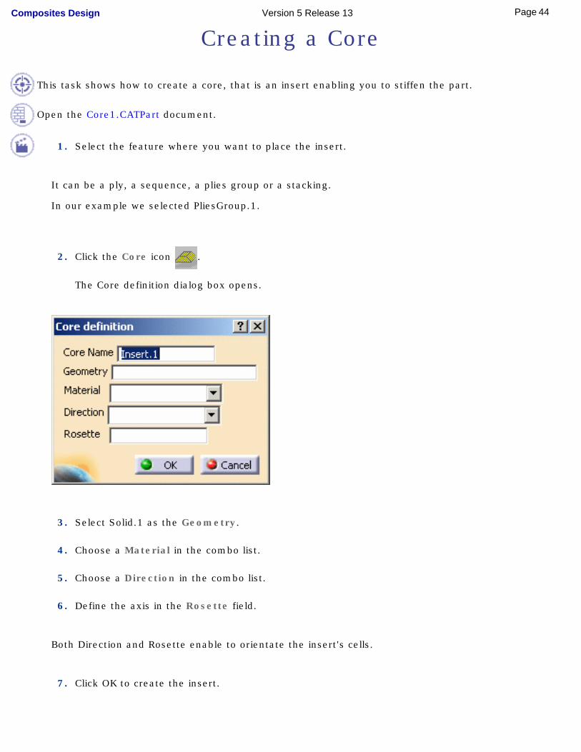
2. Click the Core icon .
The Core definition dialog box opens.
3. Select Solid.1 as the Geometry.
4. Choose a Material in the combo list.
5. Choose a Direction in the combo list.
6. Define the axis in the Rosette field.
Both Direction and Rosette enable to orientate the insert's cells.
7. Click OK to create the insert.
44Page Composites Design Version 5 Release 13
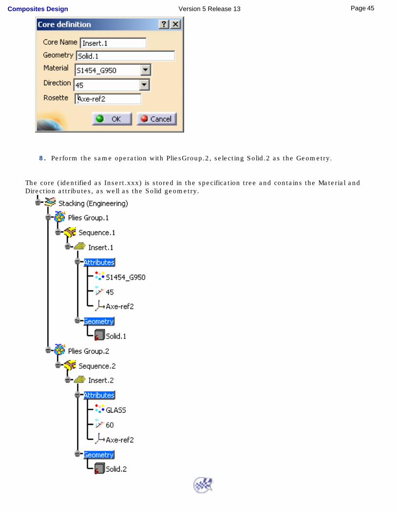
8. Perform the same operation with PliesGroup.2, selecting Solid.2 as the Geometry.
The core (identified as Insert.xxx) is stored in the specification tree and contains the Material and Direction attributes, as well as the Solid geometry.
45Page Composites Design Version 5 Release 13
Creating a Stack-Up File From Plies
This task shows you how to create a stack-up file once you created the plies.It contains the stacking order of the Composites part.
Plies must already exist.Open the Stack-UpFile2.CATPart document.
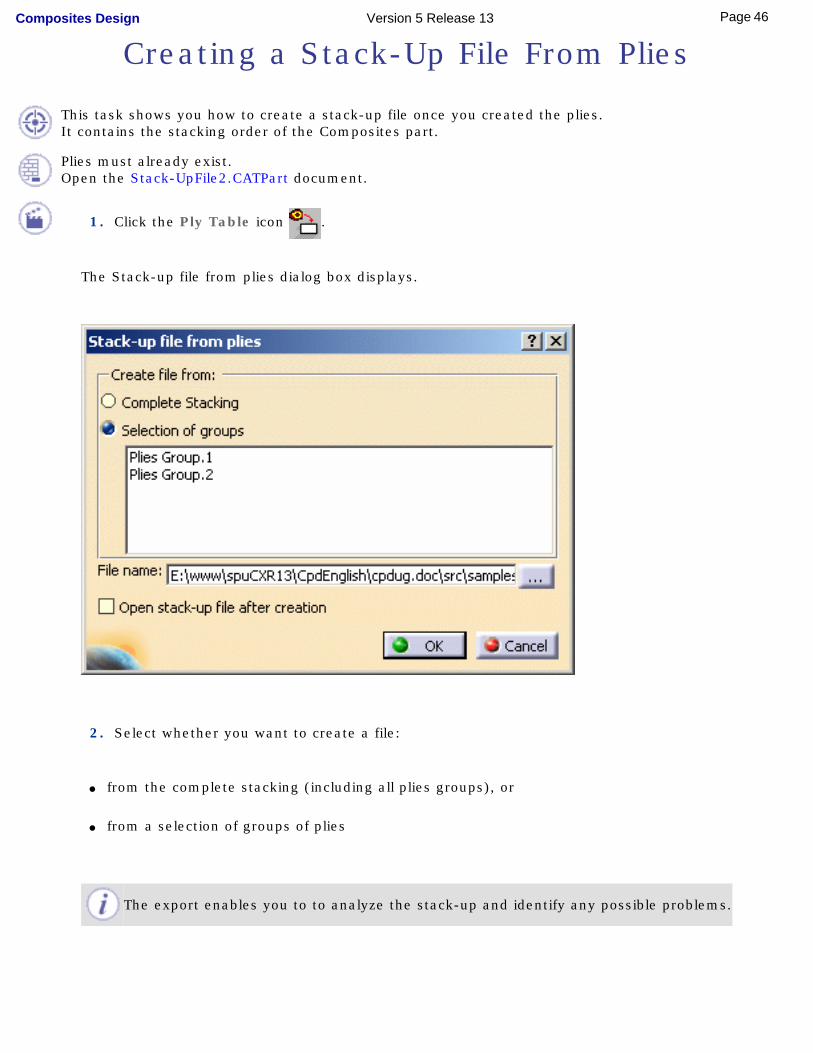
1. Click the Ply Table icon .
The Stack-up file from plies dialog box displays.
2. Select whether you want to create a file:
● from the complete stacking (including all plies groups), or
● from a selection of groups of plies
The export enables you to to analyze the stack-up and identify any possible problems.
46Page Composites Design Version 5 Release 13
3. Click the ... button to define the path where to store the stack-up file.
If you do not define any path, the file will be stored in the document's directory (here the Samples directory).
4. Click the Open stack-up file after creation to open the file once you click OK.
5. Click OK to generate the file.
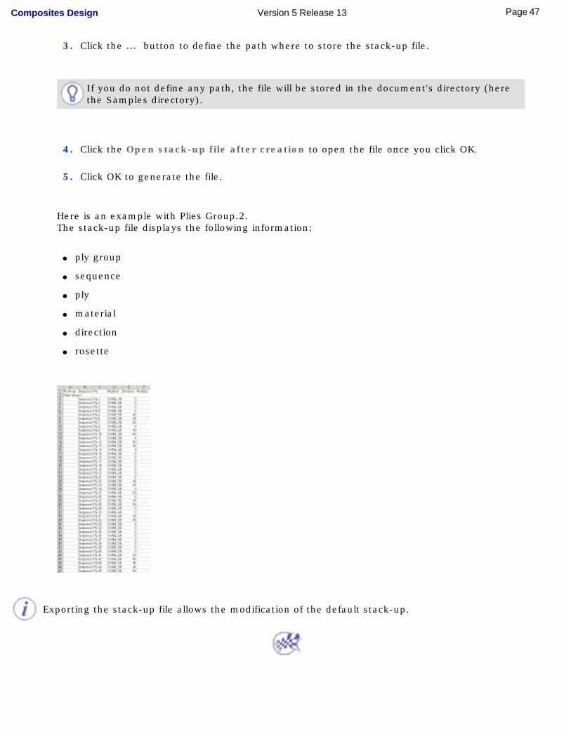
Here is an example with Plies Group.2.The stack-up file displays the following information:
● ply group
● sequence
● ply
● material
● direction
● rosette
Exporting the stack-up file allows the modification of the default stack-up.
47Page Composites Design Version 5 Release 13
Creating a Limit Contour
This task shows you how to create a limit contour feature to be able to modify the plies.
Open the LimitContour1.CATPart document.
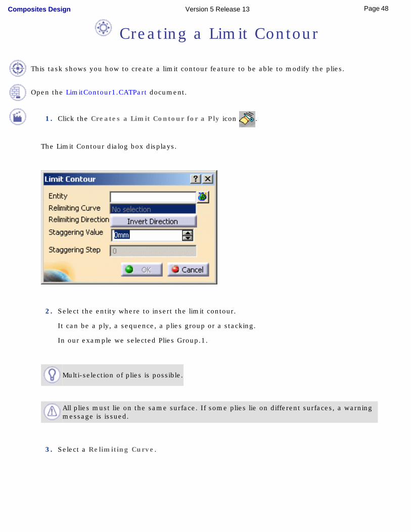
1. Click the Creates a Limit Contour for a Ply icon .
The Limit Contour dialog box displays.
2. Select the entity where to insert the limit contour.
It can be a ply, a sequence, a plies group or a stacking.
In our example we selected Plies Group.1.
Multi-selection of plies is possible.
All plies must lie on the same surface. If some plies lie on different surfaces, a warning message is issued.
3. Select a Relimiting Curve.
48Page Composites Design Version 5 Release 13
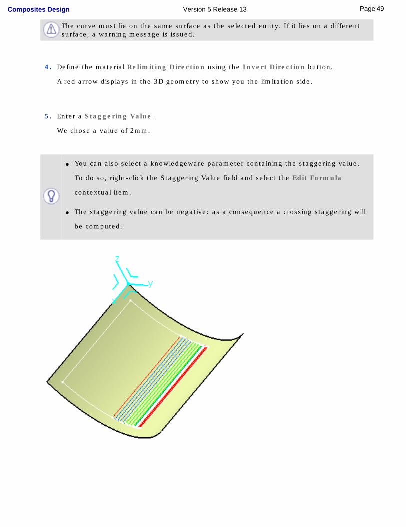
The curve must lie on the same surface as the selected entity. If it lies on a different surface, a warning message is issued.
4. Define the material Relimiting Direction using the Invert Direction button.
A red arrow displays in the 3D geometry to show you the limitation side.
5. Enter a Staggering Value.
We chose a value of 2mm.
● You can also select a knowledgeware parameter containing the staggering value.
To do so, right-click the Staggering Value field and select the Edit Formula
contextual item.
● The staggering value can be negative: as a consequence a crossing staggering will
be computed.
49Page Composites Design Version 5 Release 13
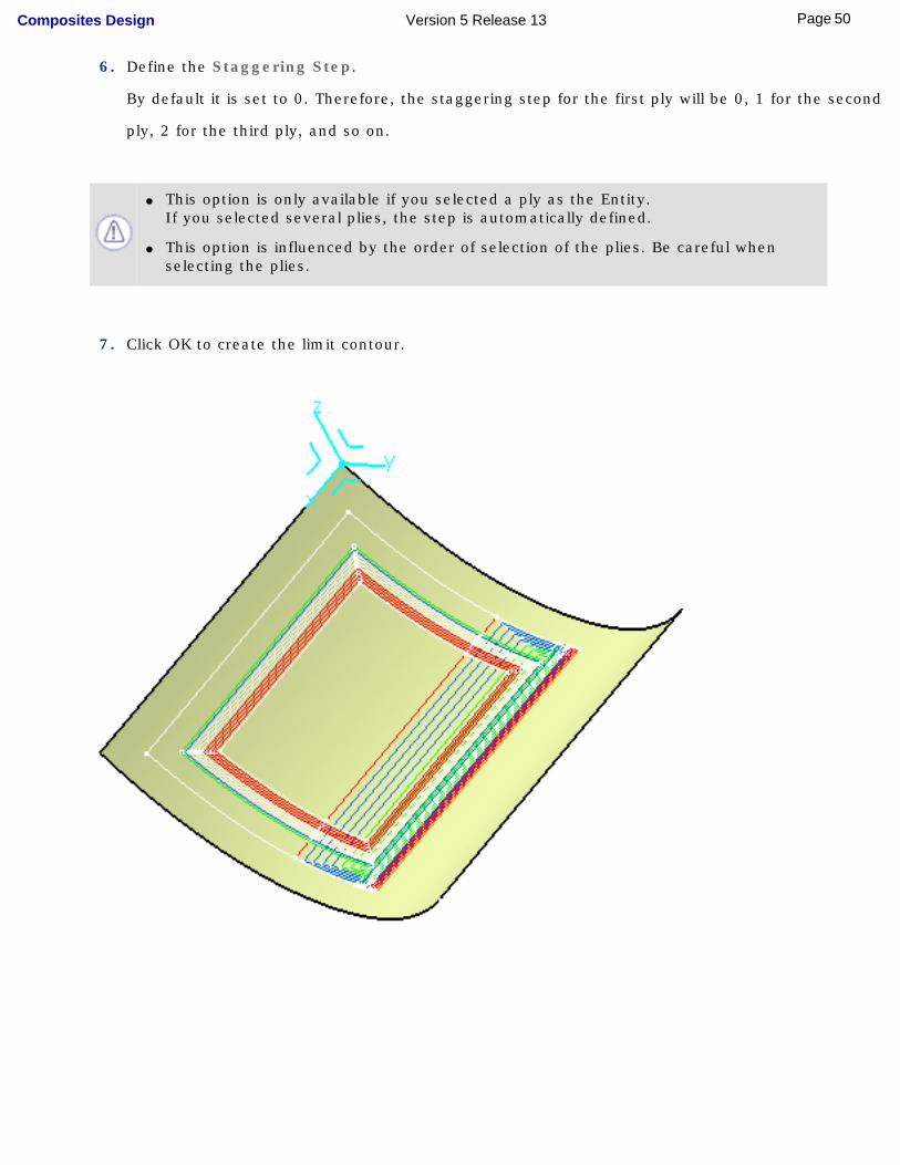
6. Define the Staggering Step.
By default it is set to 0. Therefore, the staggering step for the first ply will be 0, 1 for the second
ply, 2 for the third ply, and so on.
● This option is only available if you selected a ply as the Entity.
If you selected several plies, the step is automatically defined.
● This option is influenced by the order of selection of the plies. Be careful when selecting the plies.
7. Click OK to create the limit contour.
50Page Composites Design Version 5 Release 13
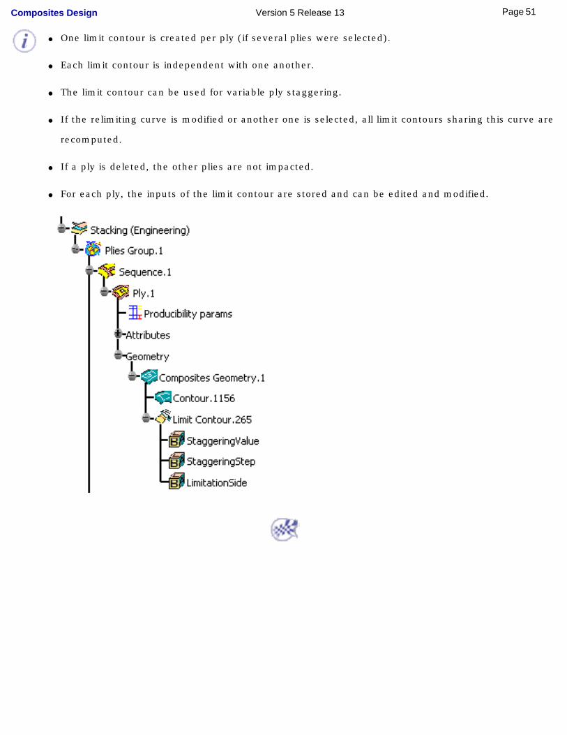
● One limit contour is created per ply (if several plies were selected).
● Each limit contour is independent with one another.
● The limit contour can be used for variable ply staggering.
● If the relimiting curve is modified or another one is selected, all limit contours sharing this curve are
recomputed.
● If a ply is deleted, the other plies are not impacted.
● For each ply, the inputs of the limit contour are stored and can be edited and modified.
51Page Composites Design Version 5 Release 13
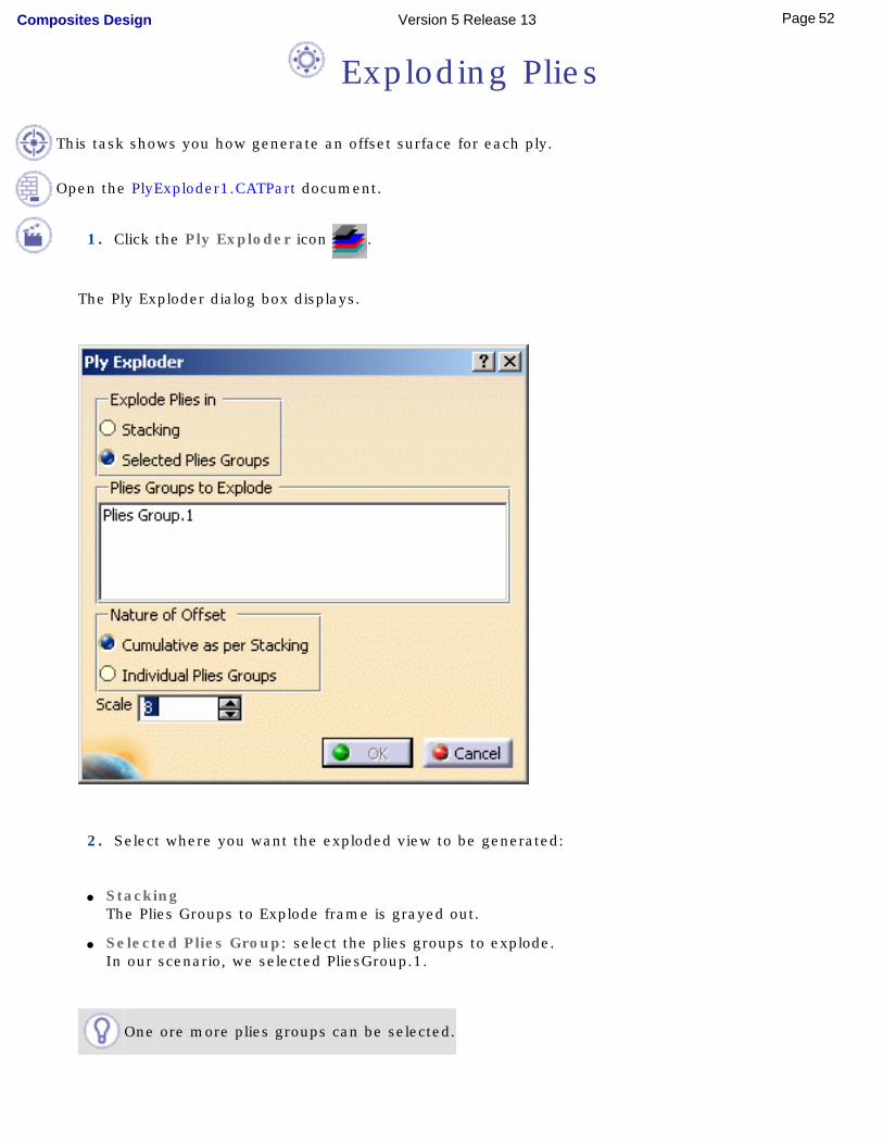
Exploding Plies
This task shows you how generate an offset surface for each ply.
Open the PlyExploder1.CATPart document.
1. Click the Ply Exploder icon .
The Ply Exploder dialog box displays.
2. Select where you want the exploded view to be generated:
● StackingThe Plies Groups to Explode frame is grayed out.
● Selected Plies Group: select the plies groups to explode.In our scenario, we selected PliesGroup.1.
One ore more plies groups can be selected.
52Page Composites Design Version 5 Release 13
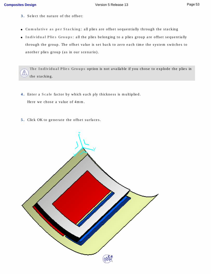
3. Select the nature of the offset:
● Cumulative as per Stacking: all plies are offset sequentially through the stacking
● Individual Plies Groups: all the plies belonging to a plies group are offset sequentially
through the group. The offset value is set back to zero each time the system switches to
another plies group (as in our scenario).
The Individual Plies Groups option is not available if you chose to explode the plies in
the stacking.
4. Enter a Scale factor by which each ply thickness is multiplied.
Here we chose a value of 4mm.
5. Click OK to generate the offset surfaces.
53Page Composites Design Version 5 Release 13

AnalyzingLaunching the Numerical Analysis
Creating a Core Sampling
54Page Composites Design Version 5 Release 13
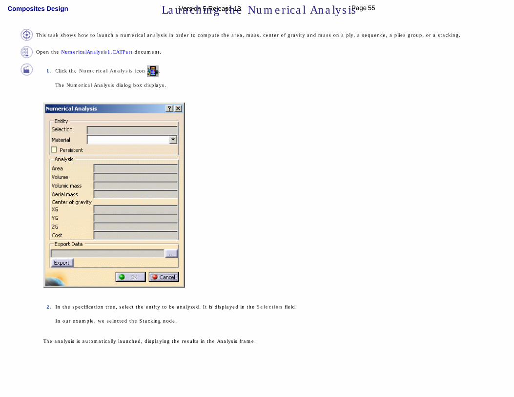
Launching the Numerical Analysis
This task shows how to launch a numerical analysis in order to compute the area, mass, center of gravity and mass on a ply, a sequence, a plies group, or a stacking.
Open the NumericalAnalysis1.CATPart document.
1. Click the Numerical Analysis icon .
The Numerical Analysis dialog box displays.
2. In the specification tree, select the entity to be analyzed. It is displayed in the Selection field.
In our example, we selected the Stacking node.
The analysis is automatically launched, displaying the results in the Analysis frame.
55Page Composites Design Version 5 Release 13
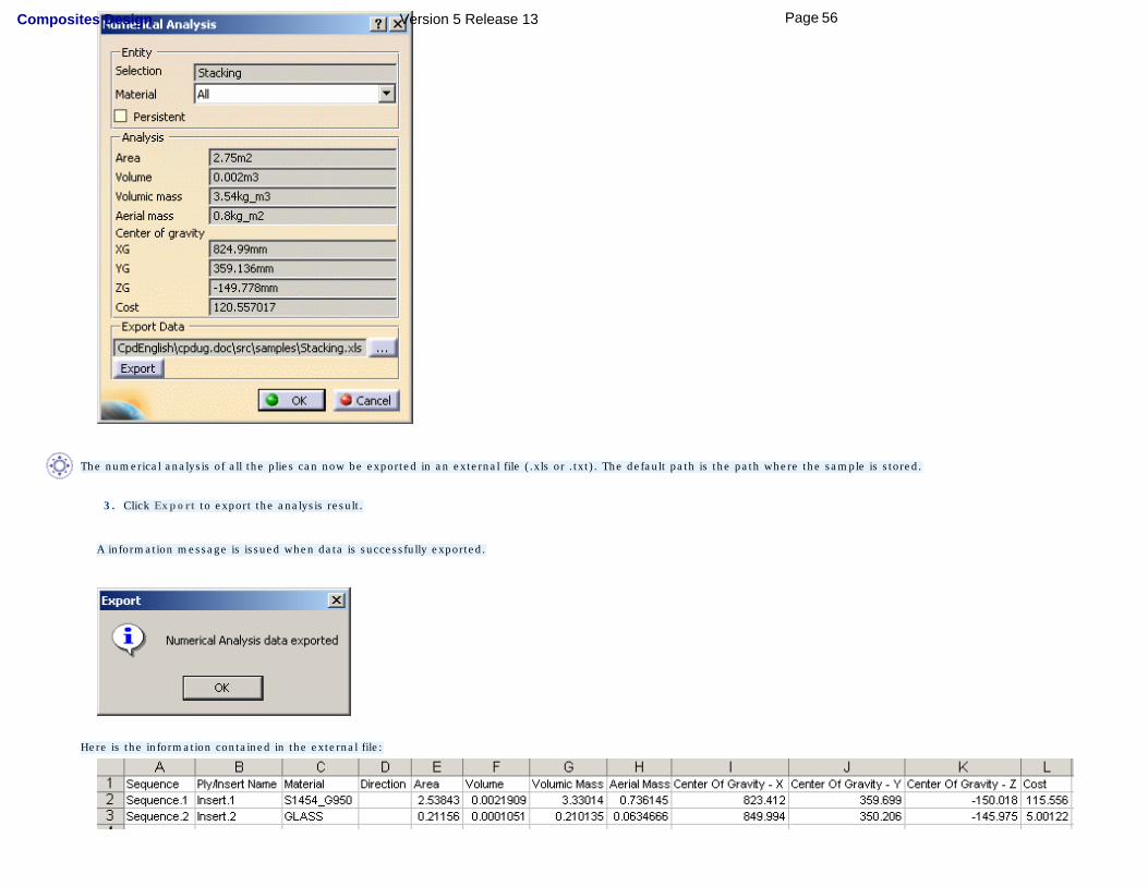
The numerical analysis of all the plies can now be exported in an external file (.xls or .txt). The default path is the path where the sample is stored.
3. Click Export to export the analysis result.
A information message is issued when data is successfully exported.
Here is the information contained in the external file:
56Page Composites Design Version 5 Release 13
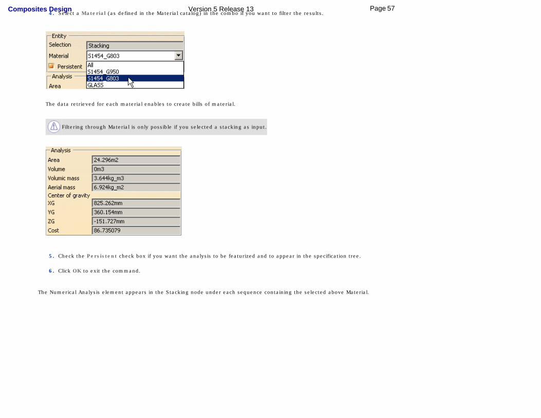
4. Select a Material (as defined in the Material catalog) in the combo if you want to filter the results.
The data retrieved for each material enables to create bills of material.
Filtering through Material is only possible if you selected a stacking as input.
5. Check the Persistent check box if you want the analysis to be featurized and to appear in the specification tree.
6. Click OK to exit the command.
The Numerical Analysis element appears in the Stacking node under each sequence containing the selected above Material.
57Page Composites Design Version 5 Release 13
58Page Composites Design Version 5 Release 13
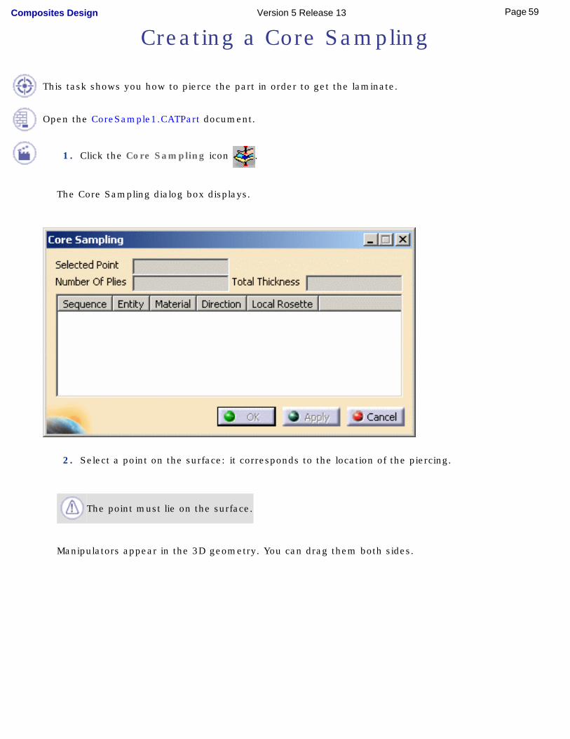
Creating a Core Sampling
This task shows you how to pierce the part in order to get the laminate.
Open the CoreSample1.CATPart document.
1. Click the Core Sampling icon .
The Core Sampling dialog box displays.
2. Select a point on the surface: it corresponds to the location of the piercing.
The point must lie on the surface.
Manipulators appear in the 3D geometry. You can drag them both sides.
59Page Composites Design Version 5 Release 13
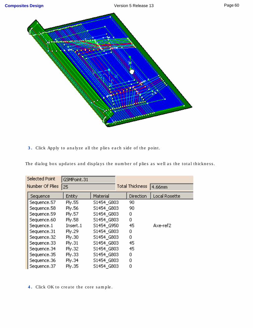
3. Click Apply to analyze all the plies each side of the point.
The dialog box updates and displays the number of plies as well as the total thickness.
4. Click OK to create the core sample.
60Page Composites Design Version 5 Release 13
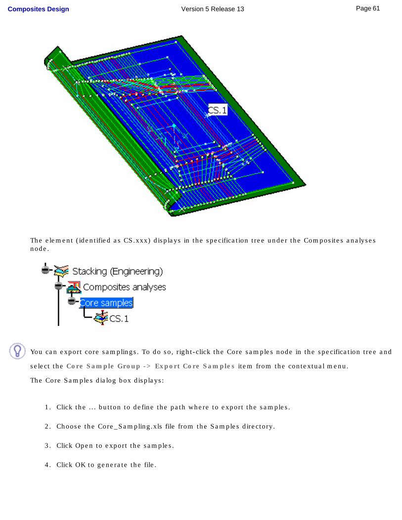
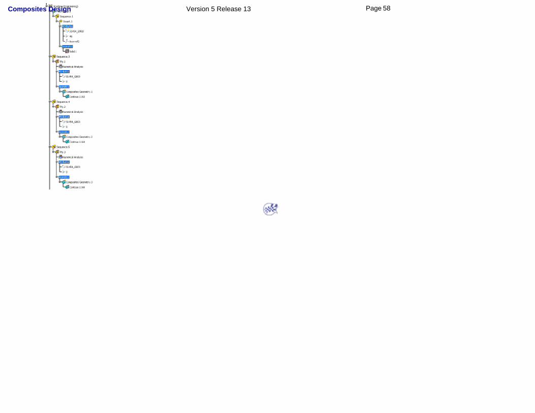
The element (identified as CS.xxx) displays in the specification tree under the Composites analyses node.
You can export core samplings. To do so, right-click the Core samples node in the specification tree and
select the Core Sample Group -> Export Core Samples item from the contextual menu.
The Core Samples dialog box displays:
1. Click the ... button to define the path where to export the samples.
2. Choose the Core_Sampling.xls file from the Samples directory.
3. Click Open to export the samples.
4. Click OK to generate the file.
61Page Composites Design Version 5 Release 13
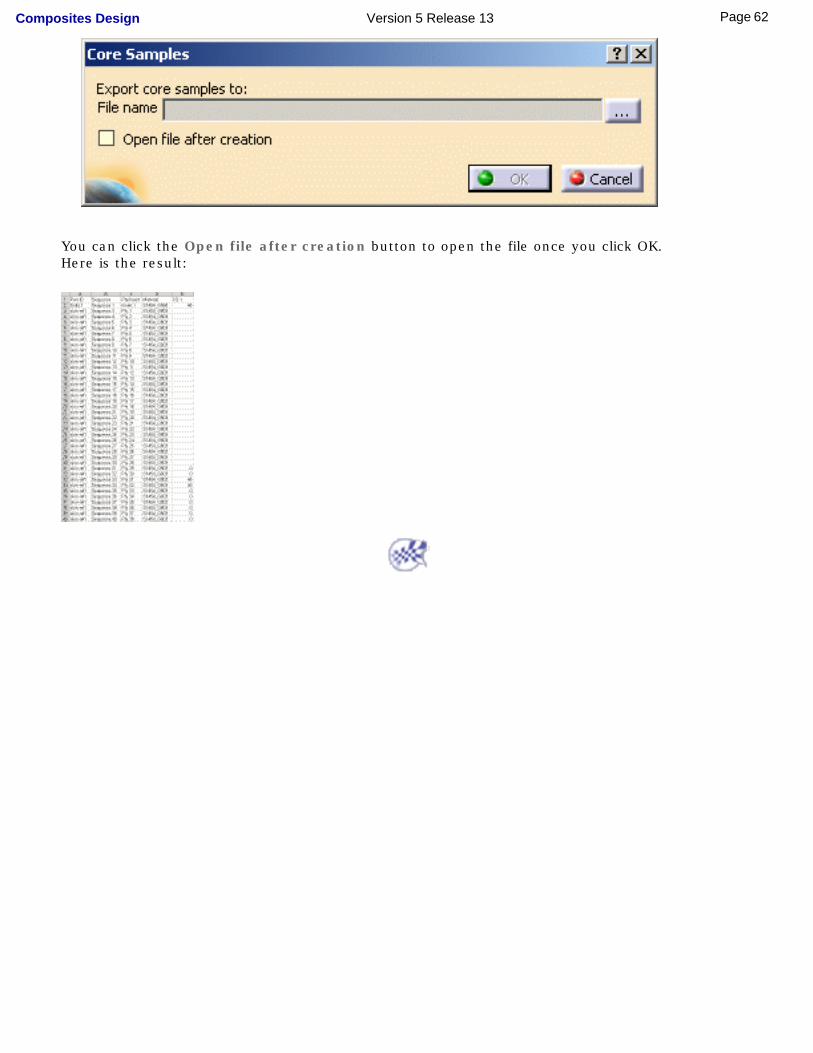
You can click the Open file after creation button to open the file once you click OK.Here is the result:
62Page Composites Design Version 5 Release 13

Creating Manufacturing ProcessCreating a Manufacturing Document
Swapping the SkinDefining the EOP
Defining the Material ExcessAnalyzing the Producibility
Flattening
63Page Composites Design Version 5 Release 13
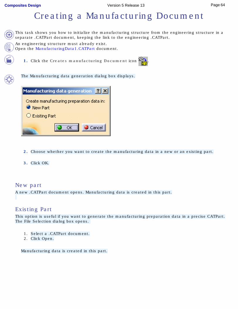
Creating a Manufacturing Document
This task shows you how to initialize the manufacturing structure from the engineering structure in a separate .CATPart document, keeping the link to the engineering .CATPart.
An engineering structure must already exist.Open the ManufacturingData1.CATPart document.
1. Click the Creates manufacturing Document icon .
The Manufacturing data generation dialog box displays.
2. Choose whether you want to create the manufacturing data in a new or an existing part.
3. Click OK.
New part A new .CATPart document opens. Manufacturing data is created in this part.
Existing Part This option is useful if you want to generate the manufacturing preparation data in a precise CATPart.
The File Selection dialog box opens.
1. Select a .CATPart document.2. Click Open.
Manufacturing data is created in this part.
64Page Composites Design Version 5 Release 13
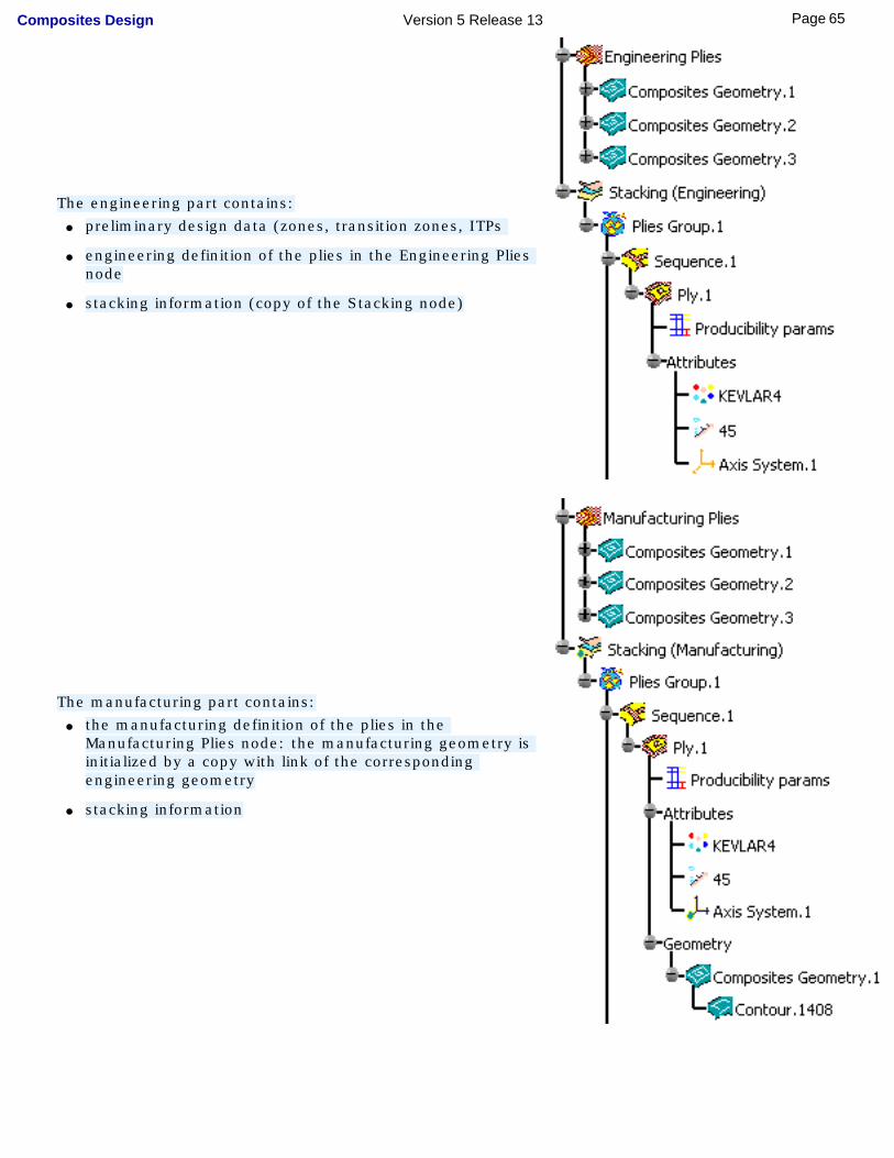
The engineering part contains:● preliminary design data (zones, transition zones, ITPs
● engineering definition of the plies in the Engineering Plies node
● stacking information (copy of the Stacking node)
The manufacturing part contains:● the manufacturing definition of the plies in the
Manufacturing Plies node: the manufacturing geometry is initialized by a copy with link of the corresponding engineering geometry
● stacking information
65Page Composites Design Version 5 Release 13

Note that:● core samples and numerical analysis will not be generated in the manufacturing preparation data.
● only a simple copy (with no link) of the producibility parameters will be generated.
Now the Skin Swapping and Material Excess icons are available in the Manufacturing Toolbar in the
new or existing CATPart.
66Page Composites Design Version 5 Release 13
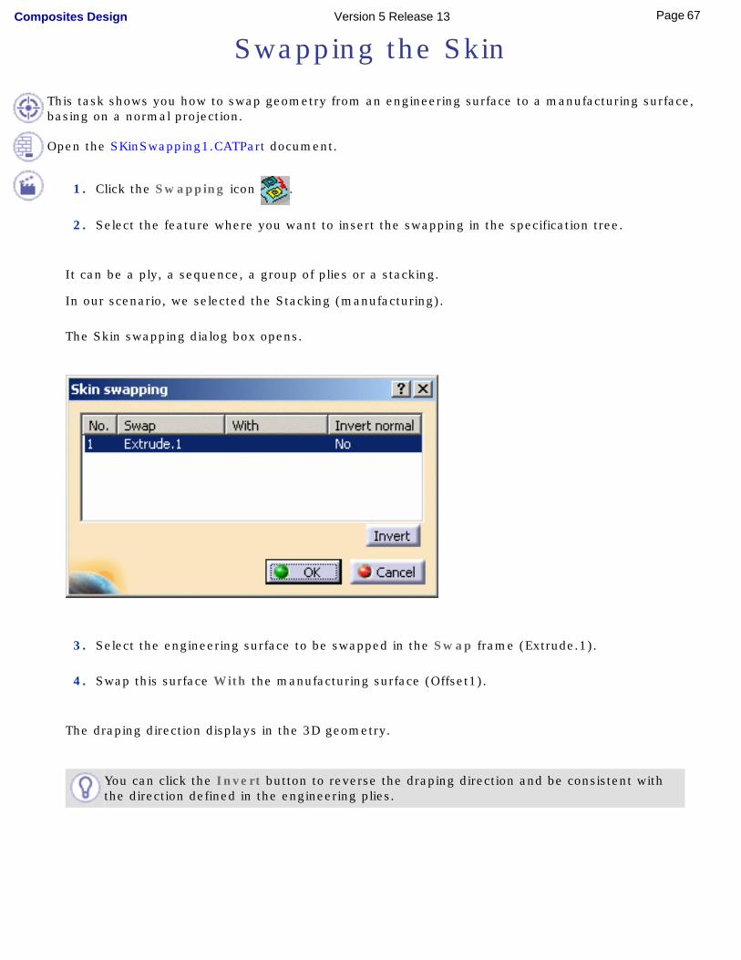
Swapping the Skin
This task shows you how to swap geometry from an engineering surface to a manufacturing surface, basing on a normal projection.
Open the SKinSwapping1.CATPart document.
1. Click the Swapping icon .
2. Select the feature where you want to insert the swapping in the specification tree.
It can be a ply, a sequence, a group of plies or a stacking.
In our scenario, we selected the Stacking (manufacturing).
The Skin swapping dialog box opens.
3. Select the engineering surface to be swapped in the Swap frame (Extrude.1).
4. Swap this surface With the manufacturing surface (Offset1).
The draping direction displays in the 3D geometry.
You can click the Invert button to reverse the draping direction and be consistent with the direction defined in the engineering plies.
67Page Composites Design Version 5 Release 13
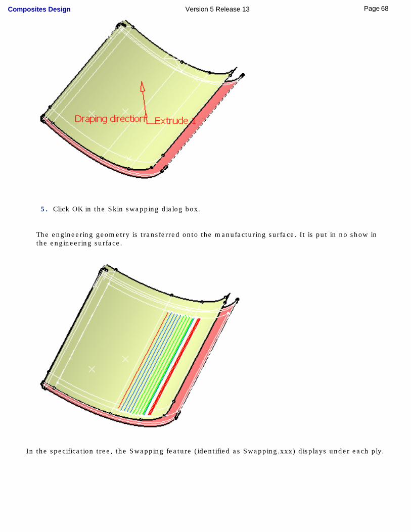
5. Click OK in the Skin swapping dialog box.
The engineering geometry is transferred onto the manufacturing surface. It is put in no show in the engineering surface.
In the specification tree, the Swapping feature (identified as Swapping.xxx) displays under each ply.
68Page Composites Design Version 5 Release 13
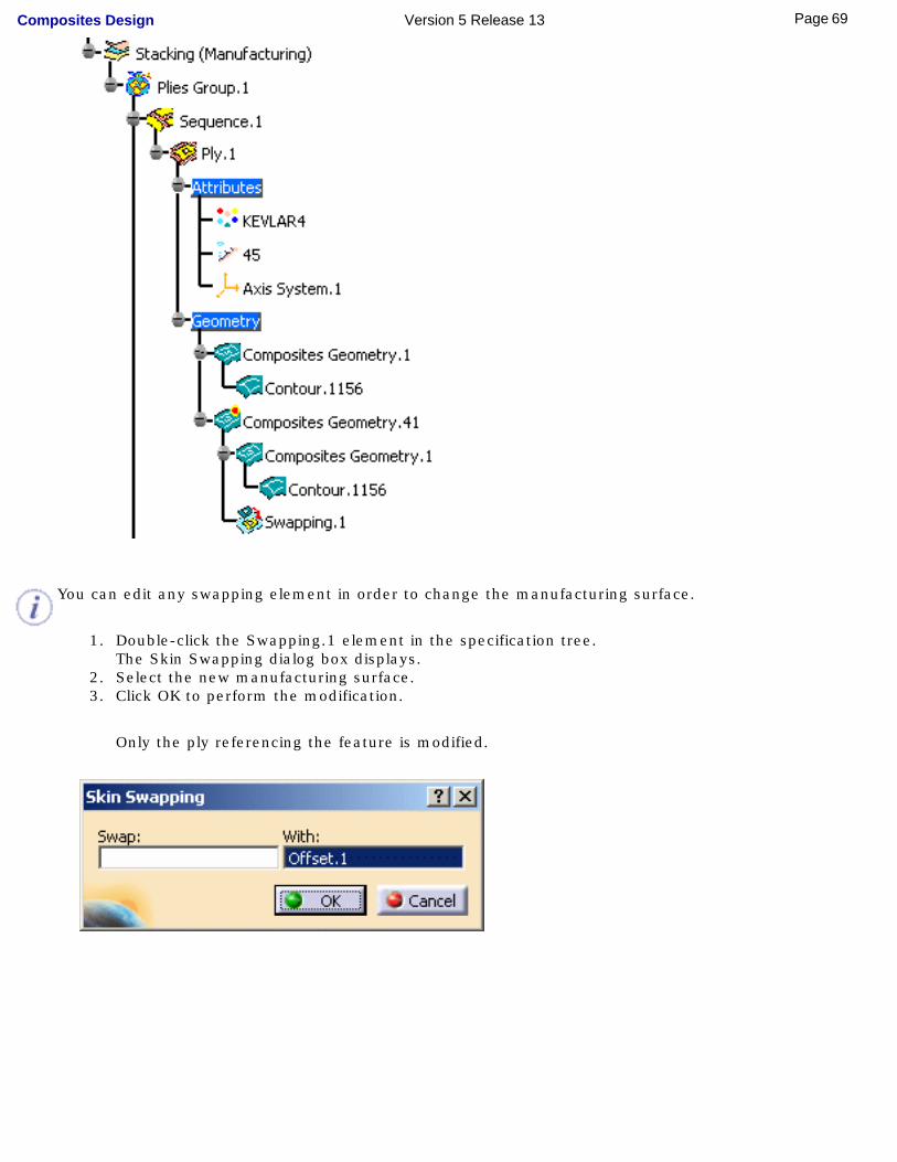
You can edit any swapping element in order to change the manufacturing surface.
1. Double-click the Swapping.1 element in the specification tree.The Skin Swapping dialog box displays.
2. Select the new manufacturing surface.3. Click OK to perform the modification.
Only the ply referencing the feature is modified.
69Page Composites Design Version 5 Release 13
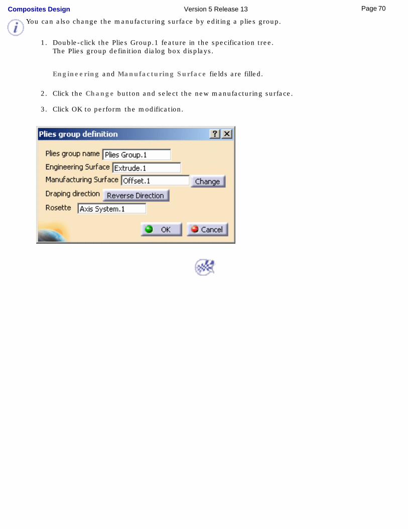
You can also change the manufacturing surface by editing a plies group.
1. Double-click the Plies Group.1 feature in the specification tree.The Plies group definition dialog box displays.
Engineering and Manufacturing Surface fields are filled.
2. Click the Change button and select the new manufacturing surface.
3. Click OK to perform the modification.
70Page Composites Design Version 5 Release 13

Defining the EOPDefining the EEOPDefining the MEOP
71Page Composites Design Version 5 Release 13
Defining the EEOP
This task shows you how to define the Engineering Edge Of Part. It corresponds to the engineering outer boundary of the plies.
Open the EEOP1.CATPart document.
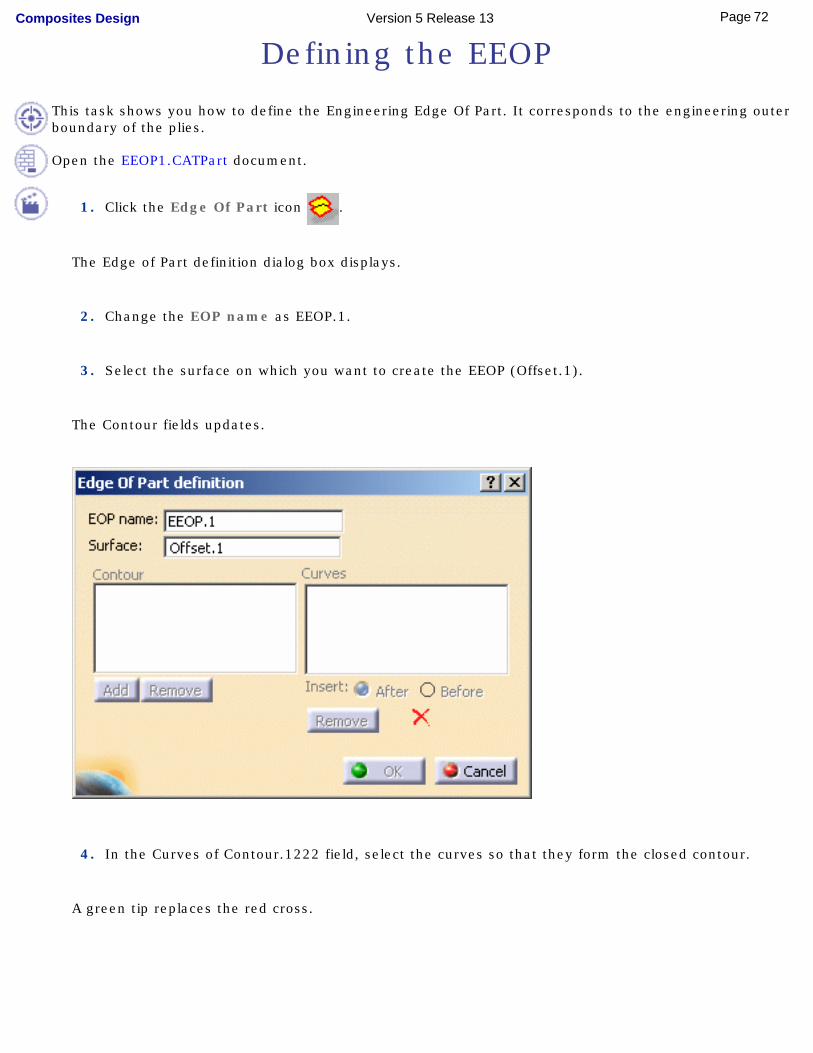
1. Click the Edge Of Part icon .
The Edge of Part definition dialog box displays.
2. Change the EOP name as EEOP.1.
3. Select the surface on which you want to create the EEOP (Offset.1).
The Contour fields updates.
4. In the Curves of Contour.1222 field, select the curves so that they form the closed contour.
A green tip replaces the red cross.
72Page Composites Design Version 5 Release 13
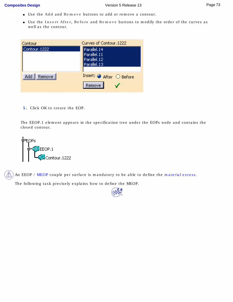
● Use the Add and Remove buttons to add or remove a contour.
● Use the Insert After, Before and Remove buttons to modify the order of the curves as well as the contour.
5. Click OK to create the EOP.
The EEOP.1 element appears in the specification tree under the EOPs node and contains the closed contour.
An EEOP / MEOP couple per surface is mandatory to be able to define the material excess.
The following task precisely explains how to define the MEOP.
73Page Composites Design Version 5 Release 13
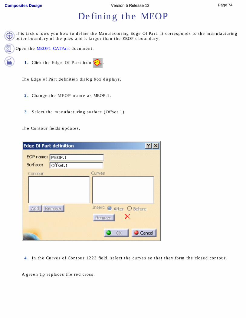
Defining the MEOP
This task shows you how to define the Manufacturing Edge Of Part. It corresponds to the manufacturing outer boundary of the plies and is larger than the EEOP's boundary.
Open the MEOP1.CATPart document.
1. Click the Edge Of Part icon .
The Edge of Part definition dialog box displays.
2. Change the MEOP name as MEOP.1.
3. Select the manufacturing surface (Offset.1).
The Contour fields updates.
4. In the Curves of Contour.1223 field, select the curves so that they form the closed contour.
A green tip replaces the red cross.
74Page Composites Design Version 5 Release 13
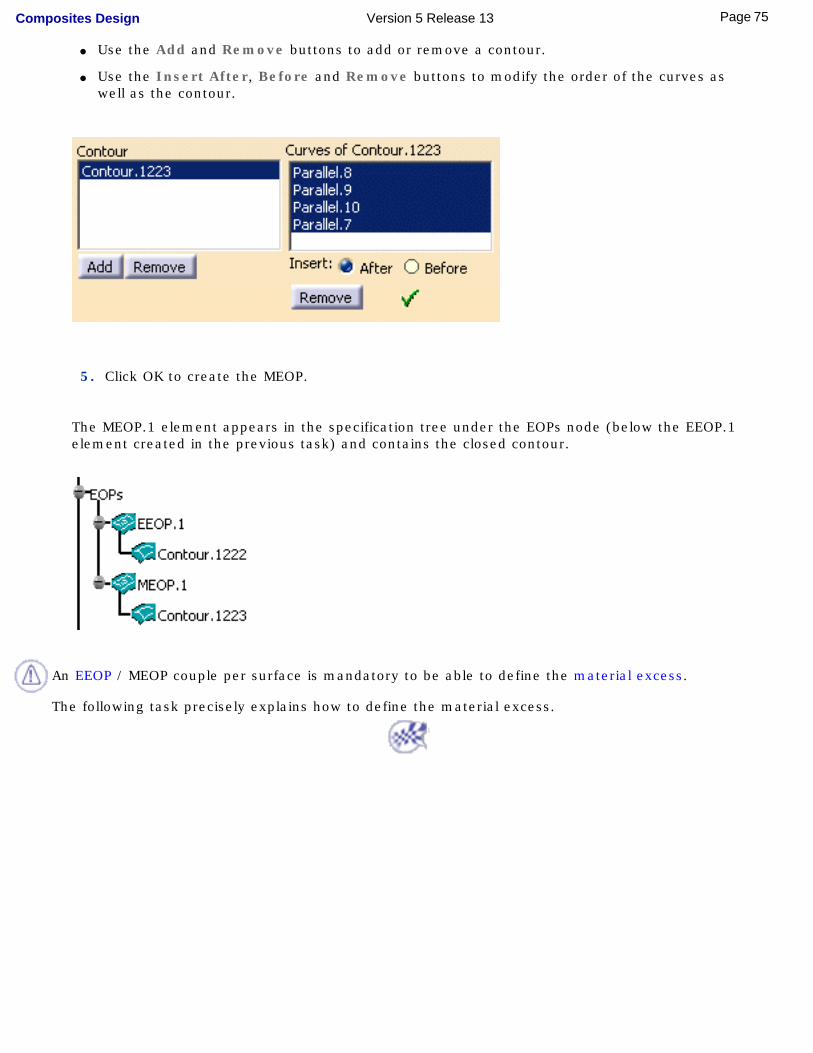
● Use the Add and Remove buttons to add or remove a contour.
● Use the Insert After, Before and Remove buttons to modify the order of the curves as well as the contour.
5. Click OK to create the MEOP.
The MEOP.1 element appears in the specification tree under the EOPs node (below the EEOP.1 element created in the previous task) and contains the closed contour.
An EEOP / MEOP couple per surface is mandatory to be able to define the material excess.
The following task precisely explains how to define the material excess.
75Page Composites Design Version 5 Release 13
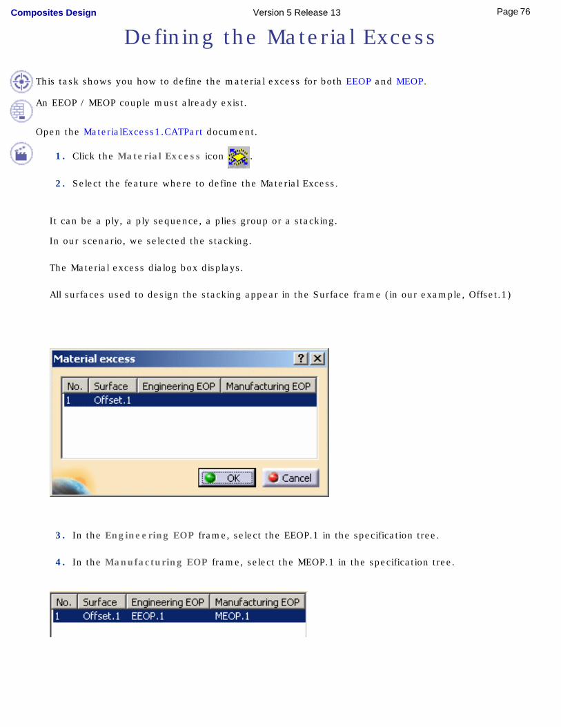
Defining the Material Excess
This task shows you how to define the material excess for both EEOP and MEOP.
An EEOP / MEOP couple must already exist.
Open the MaterialExcess1.CATPart document.
1. Click the Material Excess icon .
2. Select the feature where to define the Material Excess.
It can be a ply, a ply sequence, a plies group or a stacking.
In our scenario, we selected the stacking.
The Material excess dialog box displays.
All surfaces used to design the stacking appear in the Surface frame (in our example, Offset.1)
3. In the Engineering EOP frame, select the EEOP.1 in the specification tree.
4. In the Manufacturing EOP frame, select the MEOP.1 in the specification tree.
76Page Composites Design Version 5 Release 13
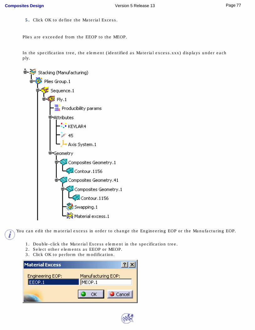
5. Click OK to define the Material Excess.
Plies are exceeded from the EEOP to the MEOP.
In the specification tree, the element (identified as Material excess.xxx) displays under each ply.
You can edit the material excess in order to change the Engineering EOP or the Manufacturing EOP.
1. Double-click the Material Excess element in the specification tree.2. Select other elements as EEOP or MEOP.3. Click OK to perform the modification.
77Page Composites Design Version 5 Release 13
Analyzing the Producibility
This task shows you how to define the producibility, that is to simulate the fibers behavior in order to detect manufacturability problems.
Open the Producibility1.CATPart document.
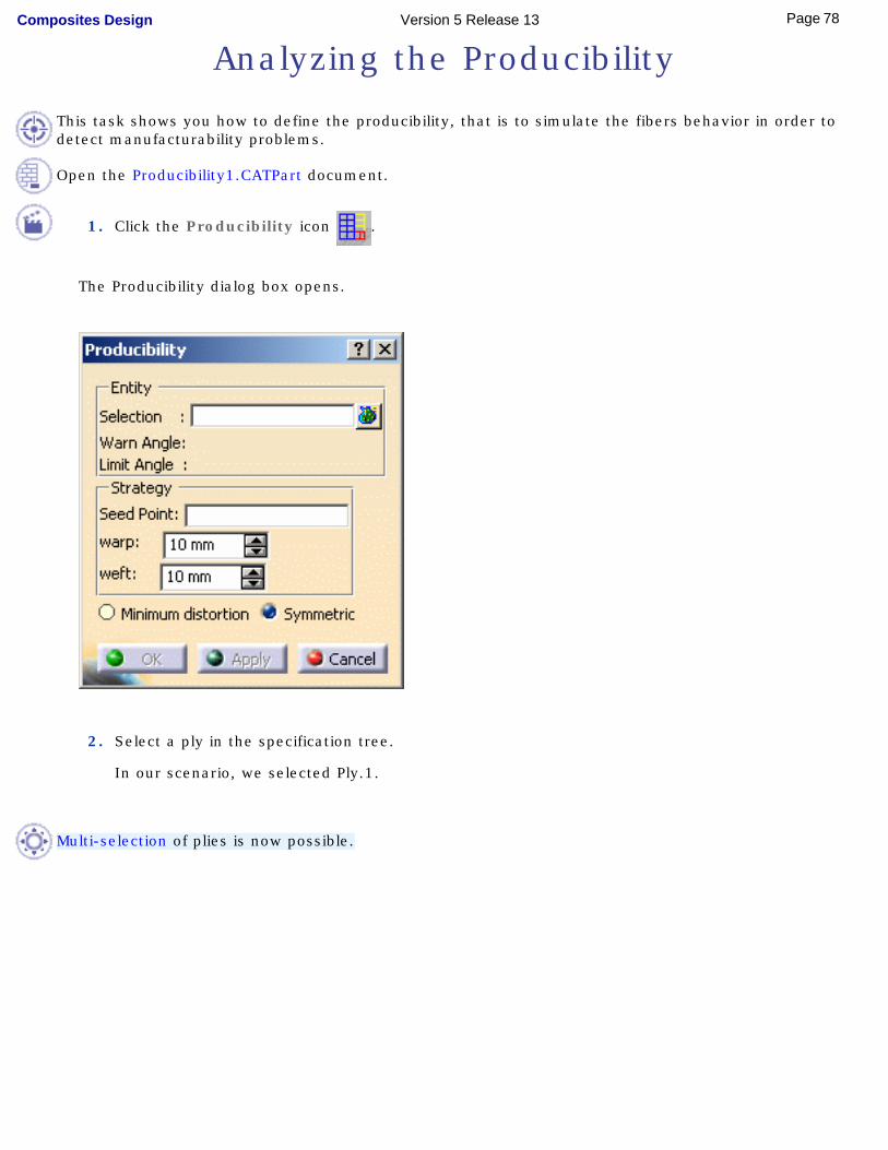
1. Click the Producibility icon .
The Producibility dialog box opens.
2. Select a ply in the specification tree.
In our scenario, we selected Ply.1.
Multi-selection of plies is now possible.
78Page Composites Design Version 5 Release 13
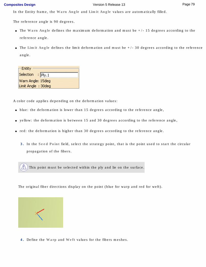
In the Entity frame, the Warn Angle and Limit Angle values are automatically filled.
The reference angle is 90 degrees.
● The Warn Angle defines the maximum deformation and must be +/- 15 degrees according to the
reference angle.
● The Limit Angle defines the limit deformation and must be +/- 30 degrees according to the reference
angle.
A color code applies depending on the deformation values:
● blue: the deformation is lower than 15 degrees according to the reference angle,
● yellow: the deformation is between 15 and 30 degrees according to the reference angle,
● red: the deformation is higher than 30 degrees according to the reference angle.
3. In the Seed Point field, select the strategy point, that is the point used to start the circular
propagation of the fibers.
This point must be selected within the ply and lie on the surface.
The original fiber directions display on the point (blue for warp and red for weft).
4. Define the Warp and Weft values for the fibers meshes.
79Page Composites Design Version 5 Release 13
● Warp: radius used to simulate the fibers behavior along the X direction.
● Weft: radius used to simulate the fibers behavior along the Y direction.
The lower the radius values are, the more precise the meshes will be.
5. Select the deformation type:
● Minimum distortion: deformation computed by the system so as to minimize the
distortion.
● Symmetric: deformation computed symmetrically regarding the fiber direction. The system
forces the propagation to be symmetrical.
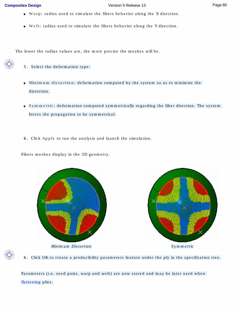
6. Click Apply to run the analysis and launch the simulation.
Fibers meshes display in the 3D geometry.
Minimum Distortion Symmetric
6. Click OK to create a producibility parameters feature under the ply in the specification tree.
Parameters (i.e. seed point, warp and weft) are now stored and may be later used when
flattening plies.
80Page Composites Design Version 5 Release 13
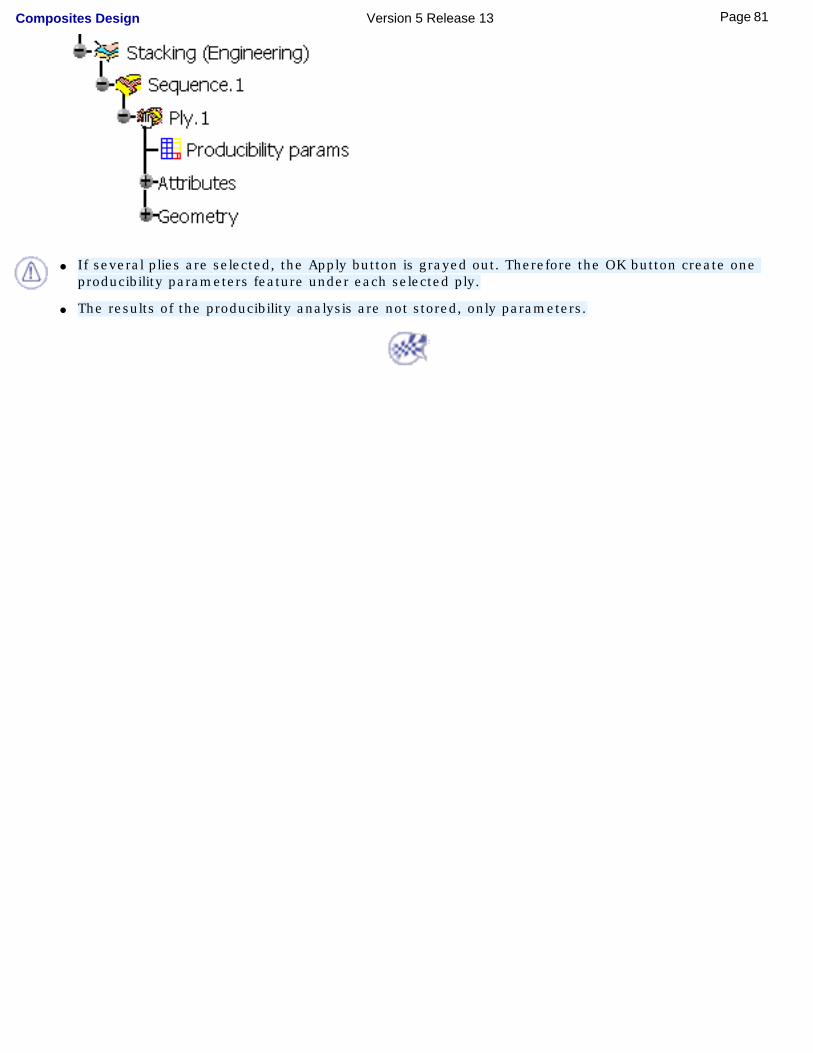
● If several plies are selected, the Apply button is grayed out. Therefore the OK button create one producibility parameters feature under each selected ply.
● The results of the producibility analysis are not stored, only parameters.
81Page Composites Design Version 5 Release 13
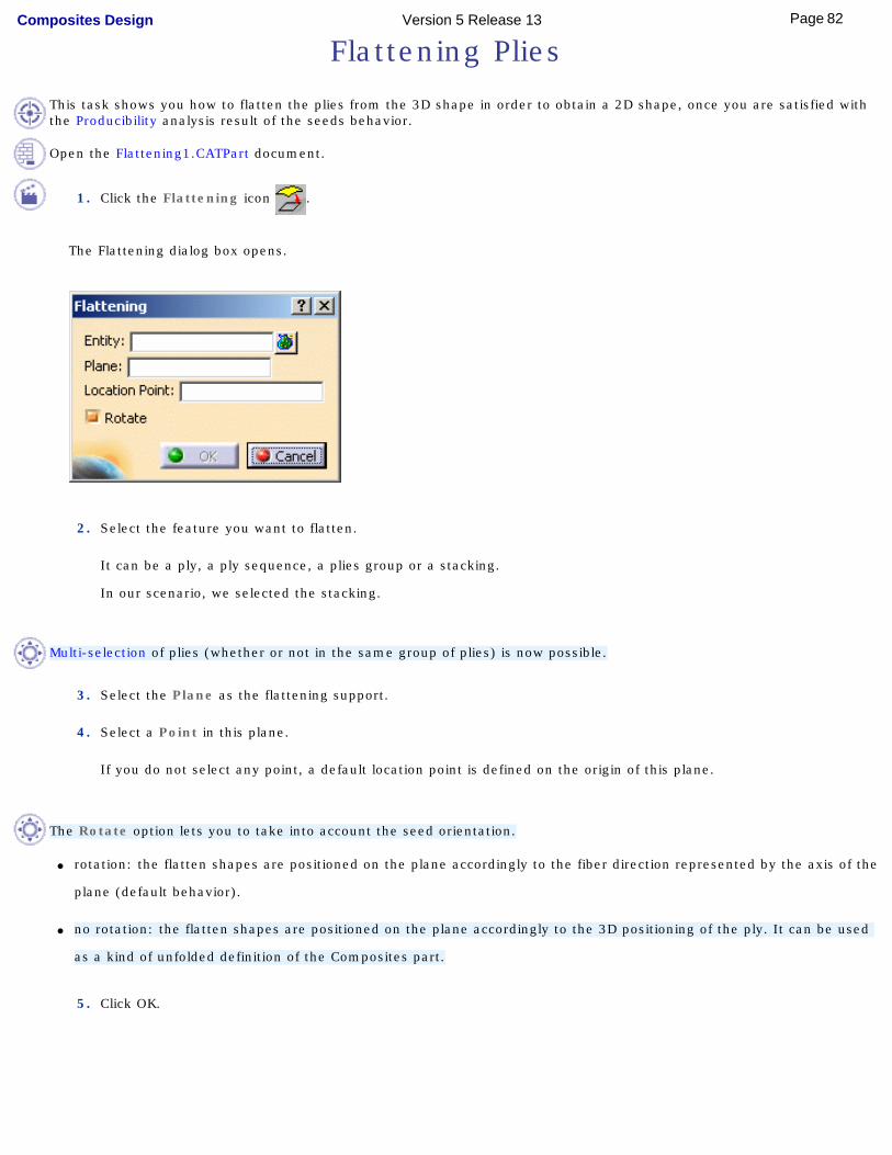
Flattening Plies
This task shows you how to flatten the plies from the 3D shape in order to obtain a 2D shape, once you are satisfied with the Producibility analysis result of the seeds behavior.
Open the Flattening1.CATPart document.
1. Click the Flattening icon .
The Flattening dialog box opens.
2. Select the feature you want to flatten.
It can be a ply, a ply sequence, a plies group or a stacking.
In our scenario, we selected the stacking.
Multi-selection of plies (whether or not in the same group of plies) is now possible.
3. Select the Plane as the flattening support.
4. Select a Point in this plane.
If you do not select any point, a default location point is defined on the origin of this plane.
The Rotate option lets you to take into account the seed orientation.
● rotation: the flatten shapes are positioned on the plane accordingly to the fiber direction represented by the axis of the
plane (default behavior).
● no rotation: the flatten shapes are positioned on the plane accordingly to the 3D positioning of the ply. It can be used
as a kind of unfolded definition of the Composites part.
5. Click OK.
82Page Composites Design Version 5 Release 13
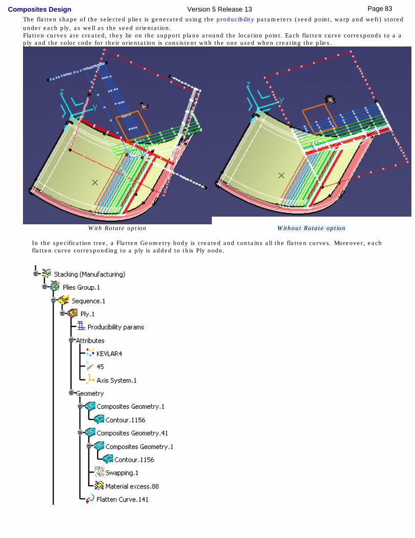
The flatten shape of the selected plies is generated using the producibility parameters (seed point, warp and weft) stored under each ply, as well as the seed orientation.Flatten curves are created, they lie on the support plane around the location point. Each flatten curve corresponds to a a ply and the color code for their orientation is consistent with the one used when creating the plies.
With Rotate option Without Rotate option In the specification tree, a Flatten Geometry body is created and contains all the flatten curves. Moreover, each
flatten curve corresponding to a ply is added to this Ply node.
83Page Composites Design Version 5 Release 13
You can reference an existing plane under a plies group. As a consequence, the plane field is already filled when you launch the Flattening command and all created flatten curves lie on this plane.
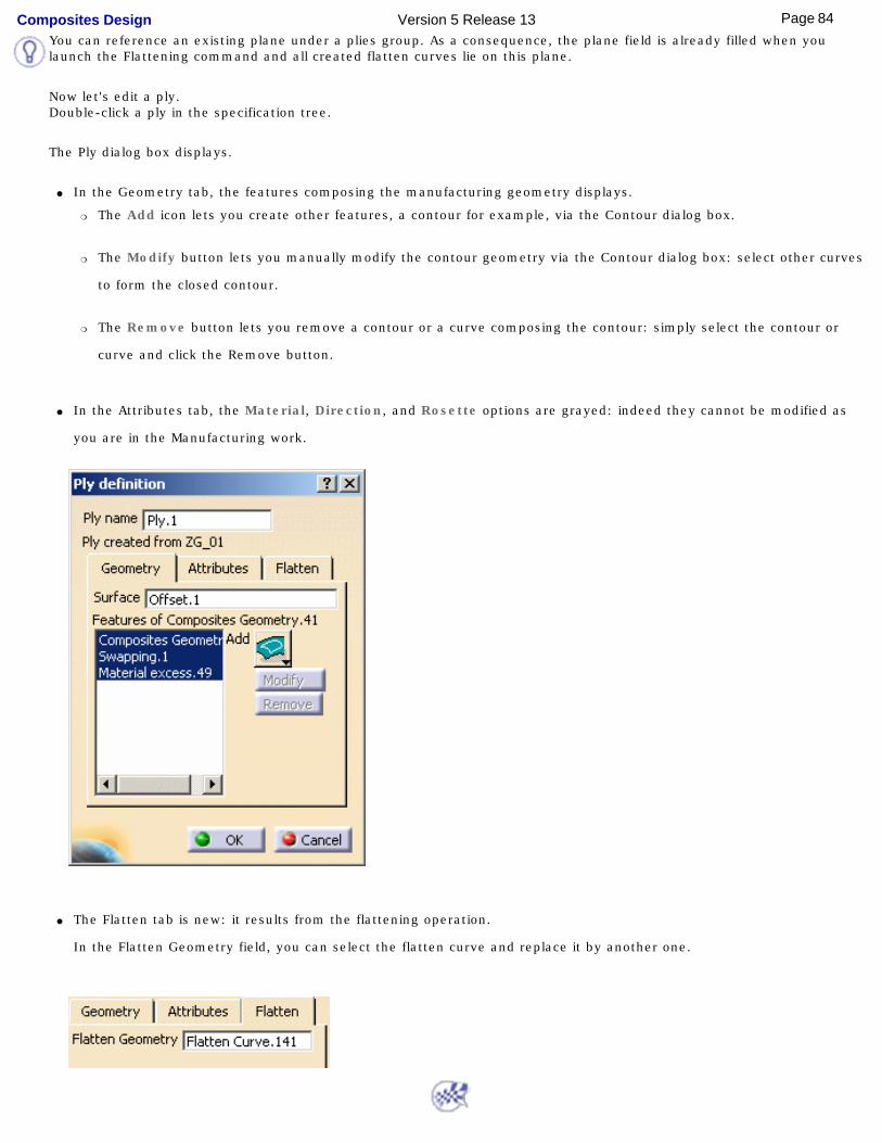
Now let's edit a ply. Double-click a ply in the specification tree.
The Ply dialog box displays.
● In the Geometry tab, the features composing the manufacturing geometry displays.
❍ The Add icon lets you create other features, a contour for example, via the Contour dialog box.
❍ The Modify button lets you manually modify the contour geometry via the Contour dialog box: select other curves
to form the closed contour.
❍ The Remove button lets you remove a contour or a curve composing the contour: simply select the contour or
curve and click the Remove button.
● In the Attributes tab, the Material, Direction, and Rosette options are grayed: indeed they cannot be modified as
you are in the Manufacturing work.
● The Flatten tab is new: it results from the flattening operation.
In the Flatten Geometry field, you can select the flatten curve and replace it by another one.
84Page Composites Design Version 5 Release 13

Exporting DataExporting Ply Data
85Page Composites Design Version 5 Release 13
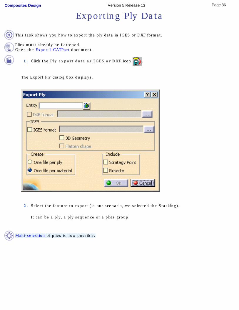
Exporting Ply Data
This task shows you how to export the ply data in IGES or DXF format.
Plies must already be flattened.Open the Export1.CATPart document.
1. Click the Ply export data as IGES or DXF icon .
The Export Ply dialog box displays.
2. Select the feature to export (in our scenario, we selected the Stacking).
It can be a ply, a ply sequence or a plies group.
Multi-selection of plies is now possible.
86Page Composites Design Version 5 Release 13
3. Select the export format.
Two formats are available:
● DXF: export in 2D (flatten geometry only).
● IGES: export in 3D.
Two options are available with this format:
❍ 3D Geometry: 3D engineering geometry and 3D manufacturing geometry
❍ Flatten shape: 3D flatten shape
You can export data using both DXF and IGES formats, as well as the options available with the IGES format (so did we in our scenario).
Default export paths are displayed, corresponding to the path where the sample is stored.You can change them by clicking the ... button.
4. Choose to create one export file:
● per ply or
● per material
The export file can include the:
● strategy point: seed point defined during the producibility analysis
● rosette: local rosette stored under each ply
This file may either contain the strategy point and/or the rosette, or none of them.
5. Click OK to export the ply data.
87Page Composites Design Version 5 Release 13
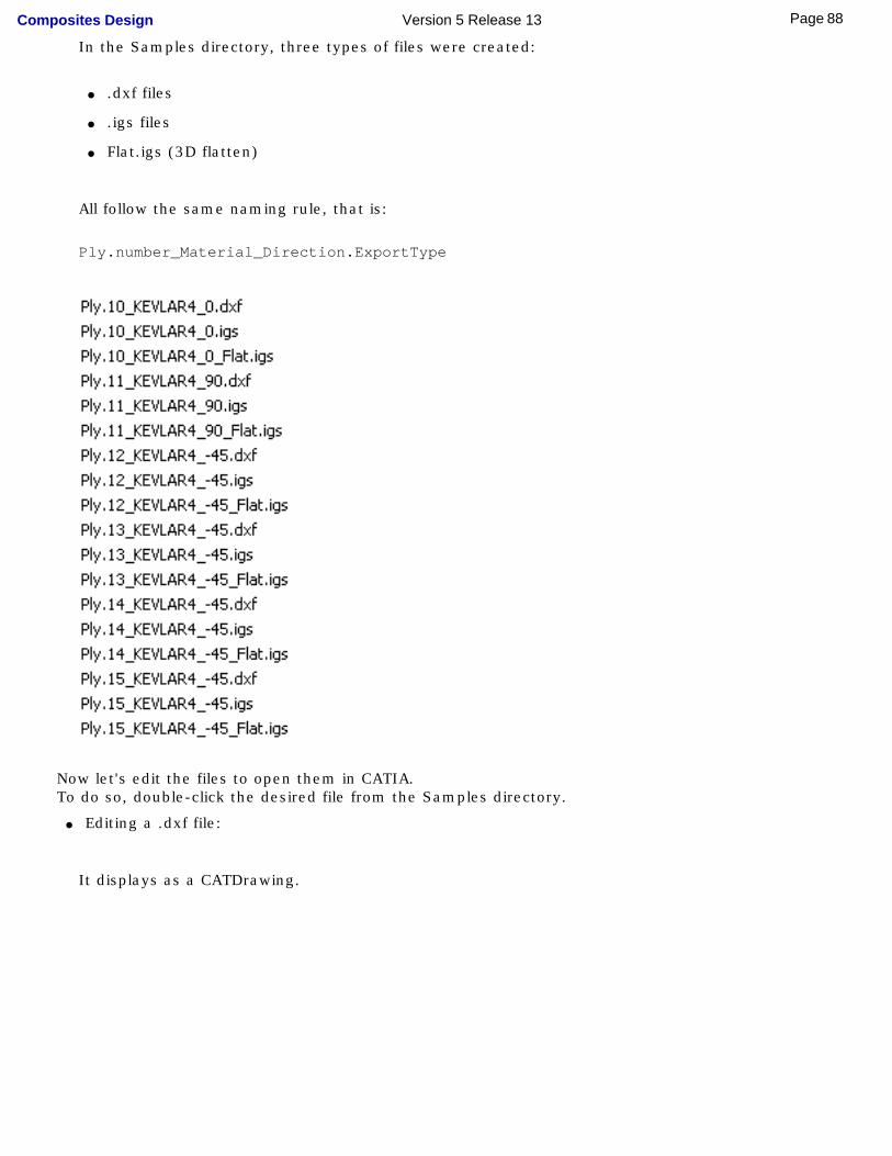
In the Samples directory, three types of files were created:
● .dxf files
● .igs files
● Flat.igs (3D flatten)
All follow the same naming rule, that is:
Ply.number_Material_Direction.ExportType
Now let's edit the files to open them in CATIA.To do so, double-click the desired file from the Samples directory.
● Editing a .dxf file:
It displays as a CATDrawing.
88Page Composites Design Version 5 Release 13
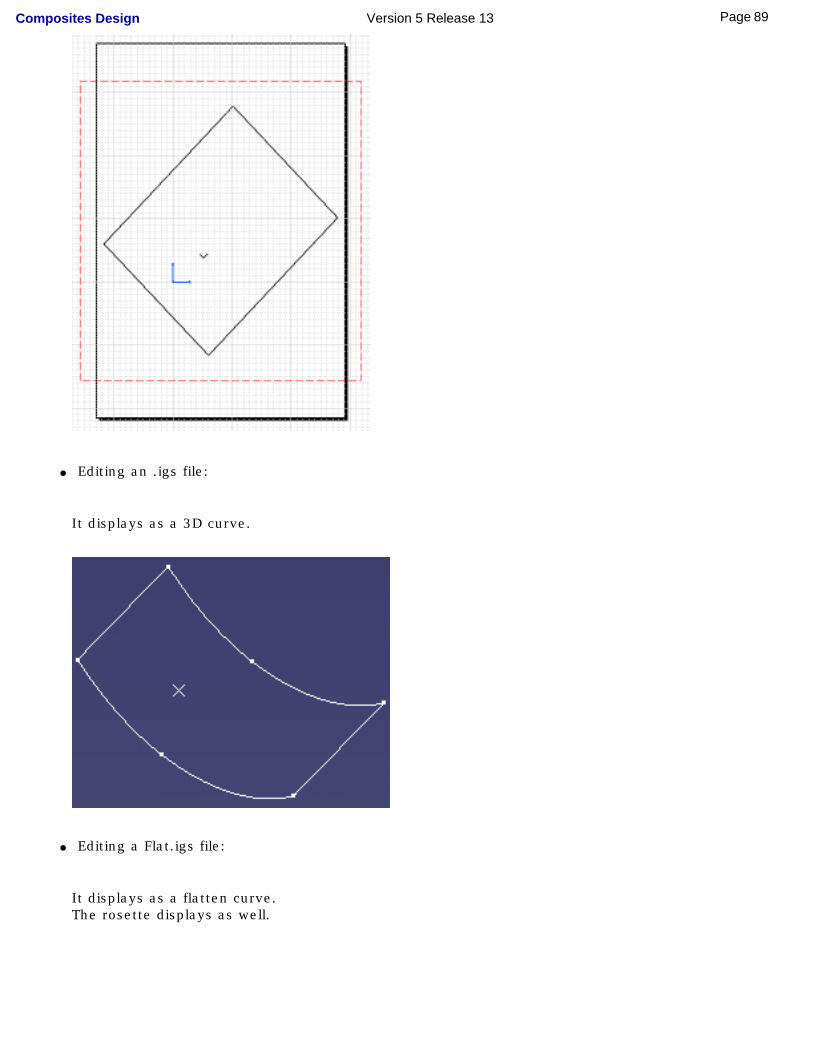
● Editing an .igs file:
It displays as a 3D curve.
● Editing a Flat.igs file:
It displays as a flatten curve.The rosette displays as well.
89Page Composites Design Version 5 Release 13
90Page Composites Design Version 5 Release 13
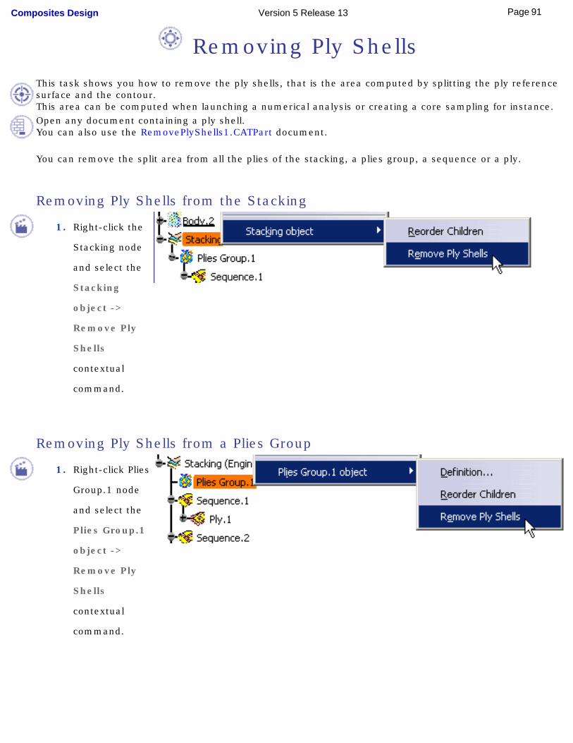
Removing Ply ShellsThis task shows you how to remove the ply shells, that is the area computed by splitting the ply reference surface and the contour.This area can be computed when launching a numerical analysis or creating a core sampling for instance.Open any document containing a ply shell. You can also use the RemovePlyShells1.CATPart document.
You can remove the split area from all the plies of the stacking, a plies group, a sequence or a ply.
Removing Ply Shells from the Stacking
1. Right-click the
Stacking node
and select the
Stacking
object ->
Remove Ply
Shells
contextual
command.
Removing Ply Shells from a Plies Group
1. Right-click Plies
Group.1 node
and select the
Plies Group.1
object ->
Remove Ply
Shells
contextual
command.
91Page Composites Design Version 5 Release 13
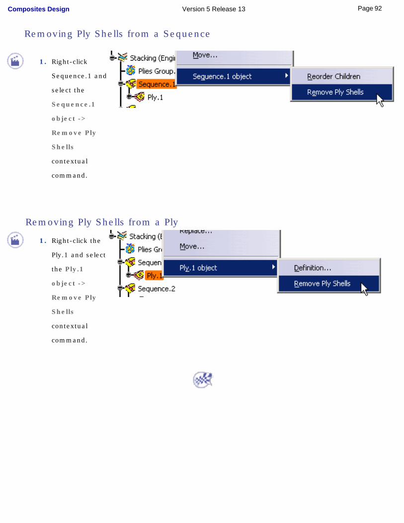
1. Right-click
Sequence.1 and
select the
Sequence.1
object ->
Remove Ply
Shells
contextual
command.
Removing Ply Shells from a Ply
1. Right-click the
Ply.1 and select
the Ply.1
object ->
Remove Ply
Shells
contextual
command.
Removing Ply Shells from a Sequence
92Page Composites Design Version 5 Release 13

Interoperability With WireframeCreating PointsCreating LinesCreating PlanesCreating Circles
[
93Page Composites Design Version 5 Release 13
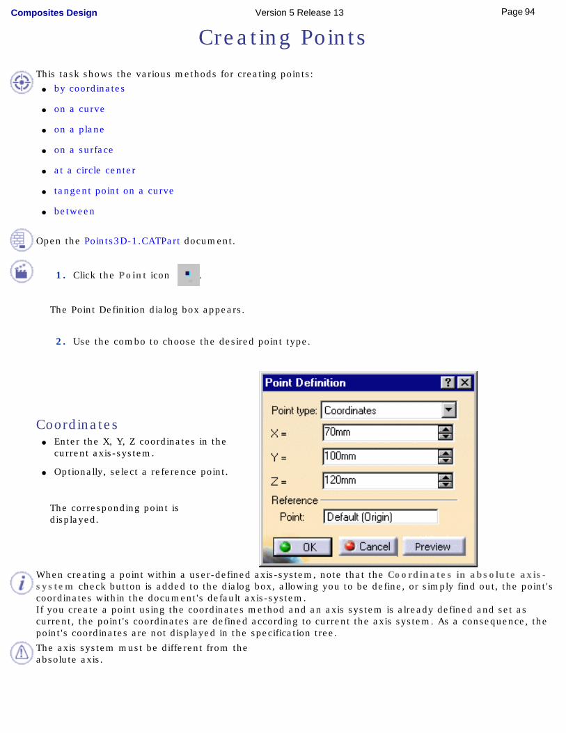
Creating Points
This task shows the various methods for creating points: ● by coordinates
● on a curve
● on a plane
● on a surface
● at a circle center
● tangent point on a curve
● between
Open the Points3D-1.CATPart document.
1. Click the Point icon .
The Point Definition dialog box appears.
2. Use the combo to choose the desired point type.
Coordinates ● Enter the X, Y, Z coordinates in the
current axis-system.
● Optionally, select a reference point.
The corresponding point is displayed.
When creating a point within a user-defined axis-system, note that the Coordinates in absolute axis-system check button is added to the dialog box, allowing you to be define, or simply find out, the point's coordinates within the document's default axis-system.If you create a point using the coordinates method and an axis system is already defined and set as current, the point's coordinates are defined according to current the axis system. As a consequence, the point's coordinates are not displayed in the specification tree.
The axis system must be different from the absolute axis.
94Page Composites Design Version 5 Release 13
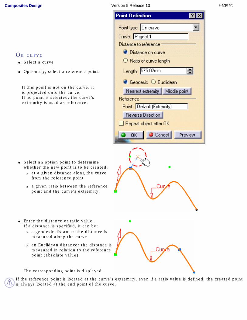
On curve ● Select a curve
● Optionally, select a reference point.
If this point is not on the curve, it is projected onto the curve.If no point is selected, the curve's extremity is used as reference.
● Select an option point to determine whether the new point is to be created:
❍ at a given distance along the curve from the reference point
❍ a given ratio between the reference point and the curve's extremity.
● Enter the distance or ratio value.
If a distance is specified, it can be: ❍ a geodesic distance: the distance is
measured along the curve
❍ an Euclidean distance: the distance is measured in relation to the reference point (absolute value).
The corresponding point is displayed.
If the reference point is located at the curve's extremity, even if a ratio value is defined, the created point is always located at the end point of the curve.
95Page Composites Design Version 5 Release 13
You can also: ● click the Nearest extremity button to display the point at the nearest extremity of the curve.
● click the Middle Point button to display the mid-point of the curve.
Be careful that the arrow is orientated towards the inside of the curve (providing the curve is not closed) when using the Middle Point option.
● use the Reverse Direction button to display: ❍ the point on the other side of the reference point (if a point was selected originally)
❍ the point from the other extremity (if no point was selected originally).
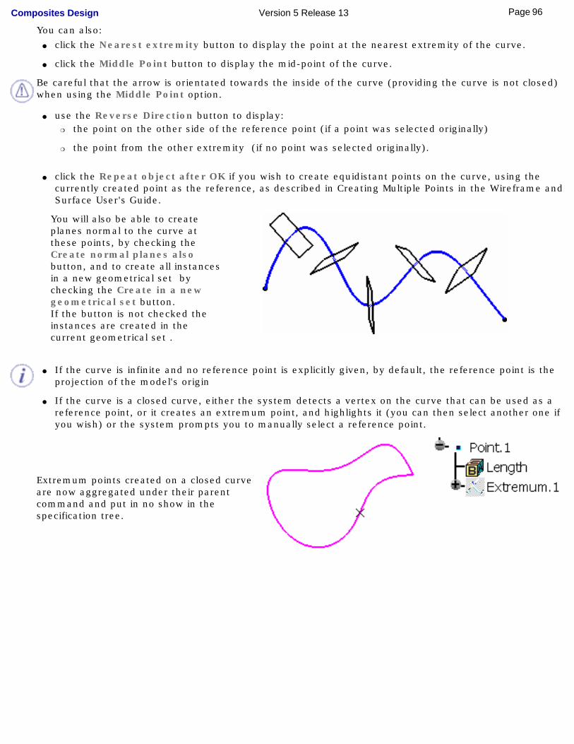
● click the Repeat object after OK if you wish to create equidistant points on the curve, using the currently created point as the reference, as described in Creating Multiple Points in the Wireframe and Surface User's Guide.
You will also be able to create planes normal to the curve at these points, by checking the Create normal planes also button, and to create all instances in a new geometrical set by checking the Create in a new geometrical set button.If the button is not checked the instances are created in the current geometrical set .
● If the curve is infinite and no reference point is explicitly given, by default, the reference point is the projection of the model's origin
● If the curve is a closed curve, either the system detects a vertex on the curve that can be used as a reference point, or it creates an extremum point, and highlights it (you can then select another one if you wish) or the system prompts you to manually select a reference point.
Extremum points created on a closed curve are now aggregated under their parent command and put in no show in the specification tree.
96Page Composites Design Version 5 Release 13
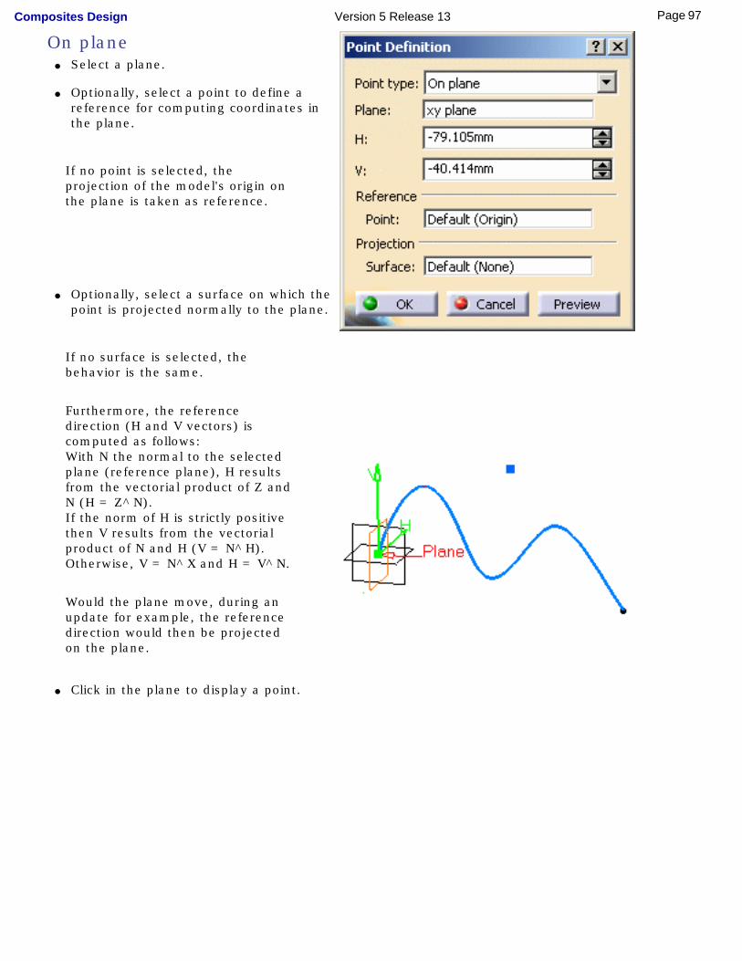
On plane ● Select a plane.
● Optionally, select a point to define a reference for computing coordinates in the plane.
If no point is selected, the projection of the model's origin on the plane is taken as reference.
● Optionally, select a surface on which the
point is projected normally to the plane.
If no surface is selected, the behavior is the same.
Furthermore, the reference direction (H and V vectors) is computed as follows: With N the normal to the selected plane (reference plane), H results from the vectorial product of Z and N (H = Z^N). If the norm of H is strictly positive then V results from the vectorial product of N and H (V = N^H).Otherwise, V = N^X and H = V^N.
Would the plane move, during an update for example, the reference direction would then be projected on the plane.
● Click in the plane to display a point.
97Page Composites Design Version 5 Release 13
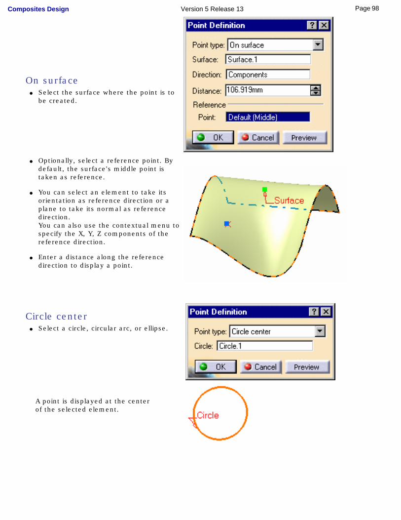
On surface ● Select the surface where the point is to
be created.
● Optionally, select a reference point. By default, the surface's middle point is taken as reference.
● You can select an element to take its orientation as reference direction or a plane to take its normal as reference direction.You can also use the contextual menu to specify the X, Y, Z components of the reference direction.
● Enter a distance along the reference direction to display a point.
Circle center ● Select a circle, circular arc, or ellipse.
A point is displayed at the center of the selected element.
98Page Composites Design Version 5 Release 13
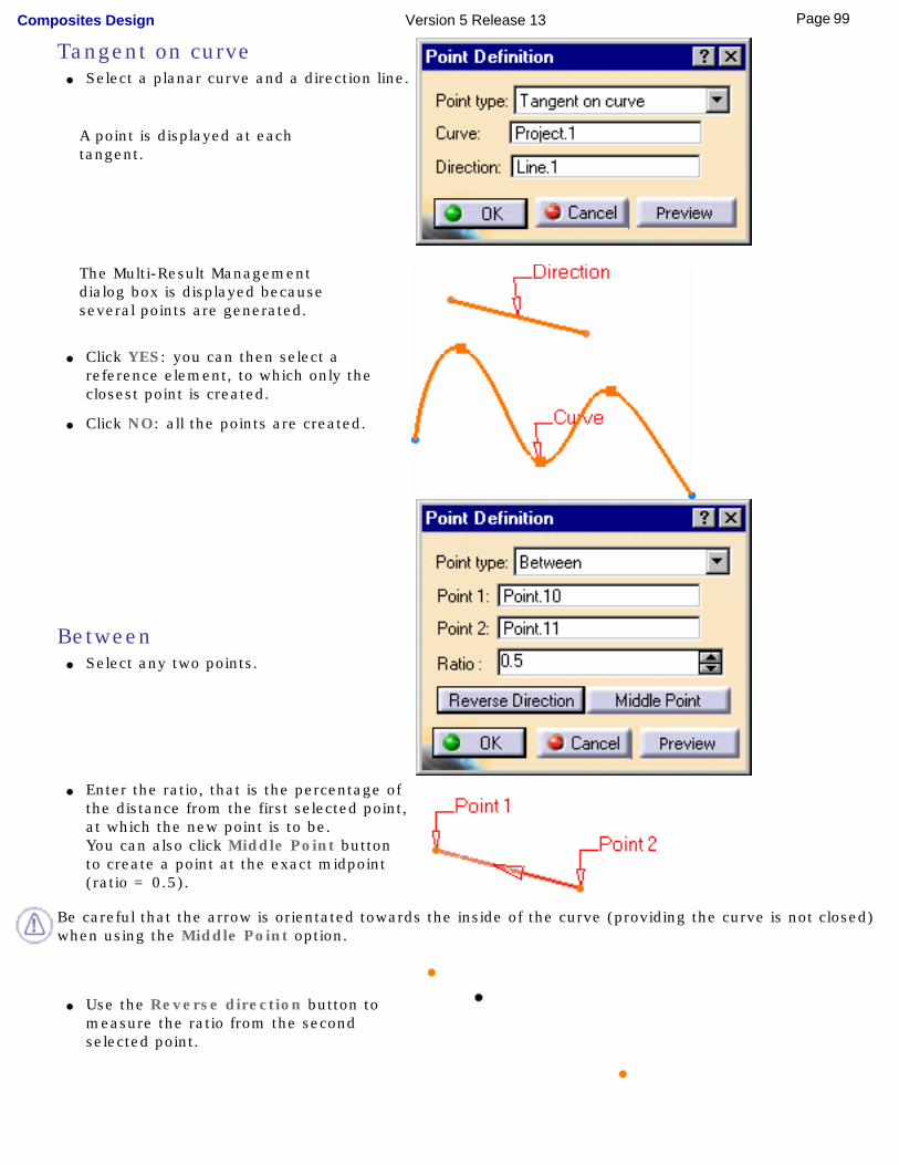
Tangent on curve ● Select a planar curve and a direction line.
A point is displayed at each tangent.
The Multi-Result Management dialog box is displayed because several points are generated.
● Click YES: you can then select a reference element, to which only the closest point is created.
● Click NO: all the points are created.
Between● Select any two points.
● Enter the ratio, that is the percentage of the distance from the first selected point, at which the new point is to be.You can also click Middle Point button to create a point at the exact midpoint (ratio = 0.5).
Be careful that the arrow is orientated towards the inside of the curve (providing the curve is not closed) when using the Middle Point option.
● Use the Reverse direction button to measure the ratio from the second selected point.
99Page Composites Design Version 5 Release 13

If the ratio value is greater than 1, the point is located on the virtual line beyond the selected points.
3. Click OK to create the point.
The point (identified as Point.xxx) is added to the specification tree.
100Page Composites Design Version 5 Release 13
Creating LinesThis task shows the various methods for creating lines:
● point to point
● point and direction
● angle or normal to curve
● tangent to curve
● normal to surface
● bisecting
It also shows you how to automatically reselect the second point.
Open the Lines1.CATPart document.
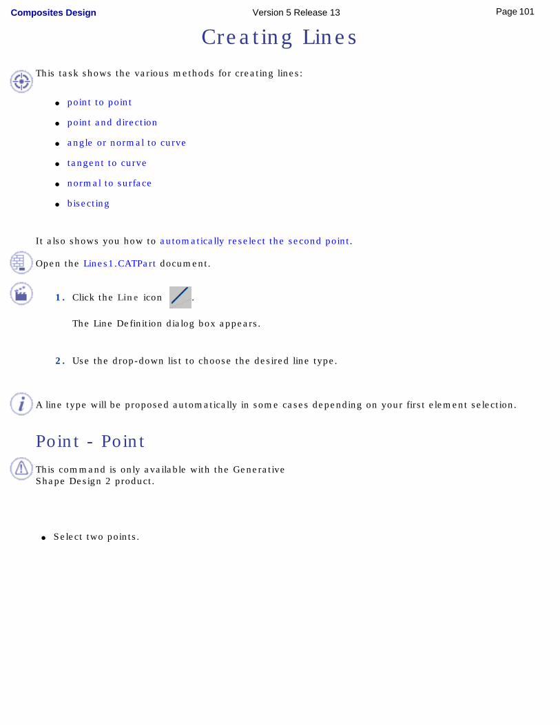
1. Click the Line icon .
The Line Definition dialog box appears.
2. Use the drop-down list to choose the desired line type.
A line type will be proposed automatically in some cases depending on your first element selection.
Point - Point
This command is only available with the Generative Shape Design 2 product.
● Select two points.
101Page Composites Design Version 5 Release 13
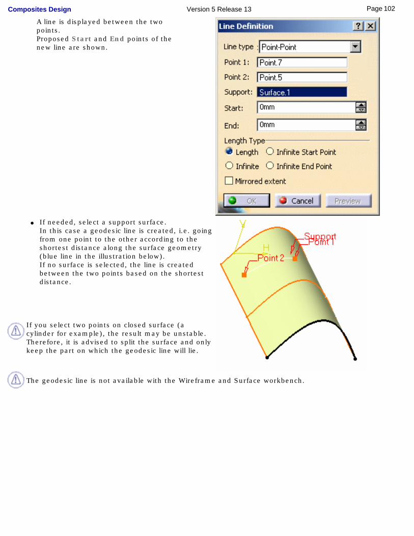
A line is displayed between the two points.Proposed Start and End points of the new line are shown.
● If needed, select a support surface.In this case a geodesic line is created, i.e. going from one point to the other according to the shortest distance along the surface geometry (blue line in the illustration below).If no surface is selected, the line is created between the two points based on the shortest distance.
If you select two points on closed surface (a cylinder for example), the result may be unstable. Therefore, it is advised to split the surface and only keep the part on which the geodesic line will lie.
The geodesic line is not available with the Wireframe and Surface workbench.
102Page Composites Design Version 5 Release 13
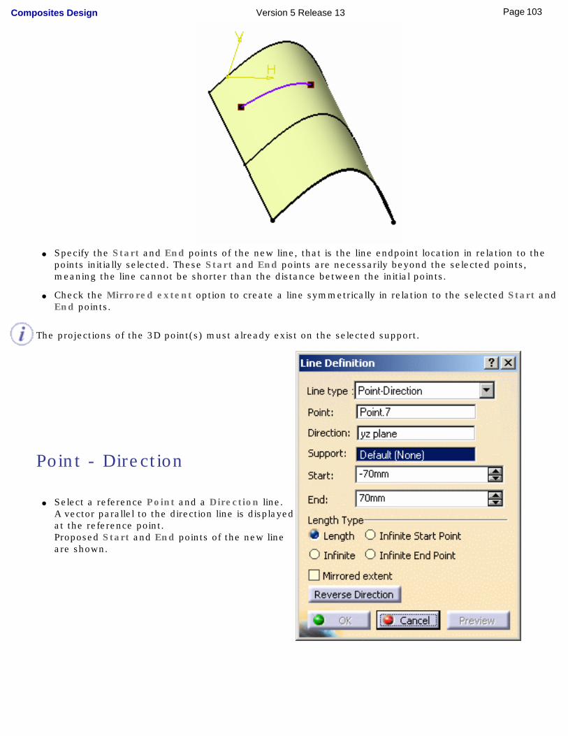
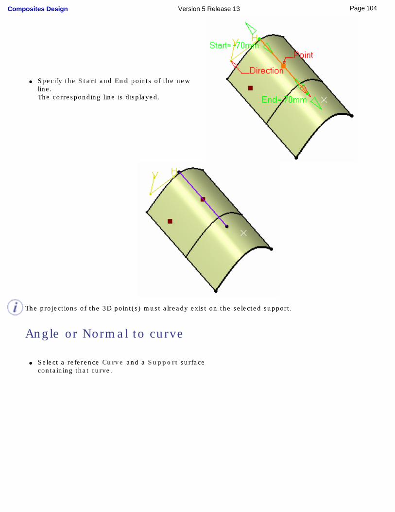
● Specify the Start and End points of the new line, that is the line endpoint location in relation to the
points initially selected. These Start and End points are necessarily beyond the selected points, meaning the line cannot be shorter than the distance between the initial points.
● Check the Mirrored extent option to create a line symmetrically in relation to the selected Start and End points.
The projections of the 3D point(s) must already exist on the selected support.
Point - Direction
● Select a reference Point and a Direction line.A vector parallel to the direction line is displayed at the reference point. Proposed Start and End points of the new line are shown.
103Page Composites Design Version 5 Release 13
● Specify the Start and End points of the new line.The corresponding line is displayed.
The projections of the 3D point(s) must already exist on the selected support.
Angle or Normal to curve
● Select a reference Curve and a Support surface containing that curve.
104Page Composites Design Version 5 Release 13
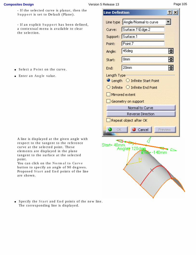
- If the selected curve is planar, then the Support is set to Default (Plane).
- If an explicit Support has been defined, a contextual menu is available to clear the selection.
● Select a Point on the curve.
● Enter an Angle value.
A line is displayed at the given angle with respect to the tangent to the reference curve at the selected point. These elements are displayed in the plane tangent to the surface at the selected point. You can click on the Normal to Curve button to specify an angle of 90 degrees. Proposed Start and End points of the line are shown.
● Specify the Start and End points of the new line.The corresponding line is displayed.
105Page Composites Design Version 5 Release 13
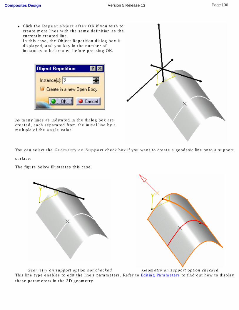
● Click the Repeat object after OK if you wish to create more lines with the same definition as the currently created line. In this case, the Object Repetition dialog box is displayed, and you key in the number of instances to be created before pressing OK.
As many lines as indicated in the dialog box are created, each separated from the initial line by a multiple of the angle value.
You can select the Geometry on Support check box if you want to create a geodesic line onto a support
surface.
The figure below illustrates this case.
Geometry on support option not checked Geometry on support option checked
This line type enables to edit the line's parameters. Refer to Editing Parameters to find out how to display these parameters in the 3D geometry.
106Page Composites Design Version 5 Release 13
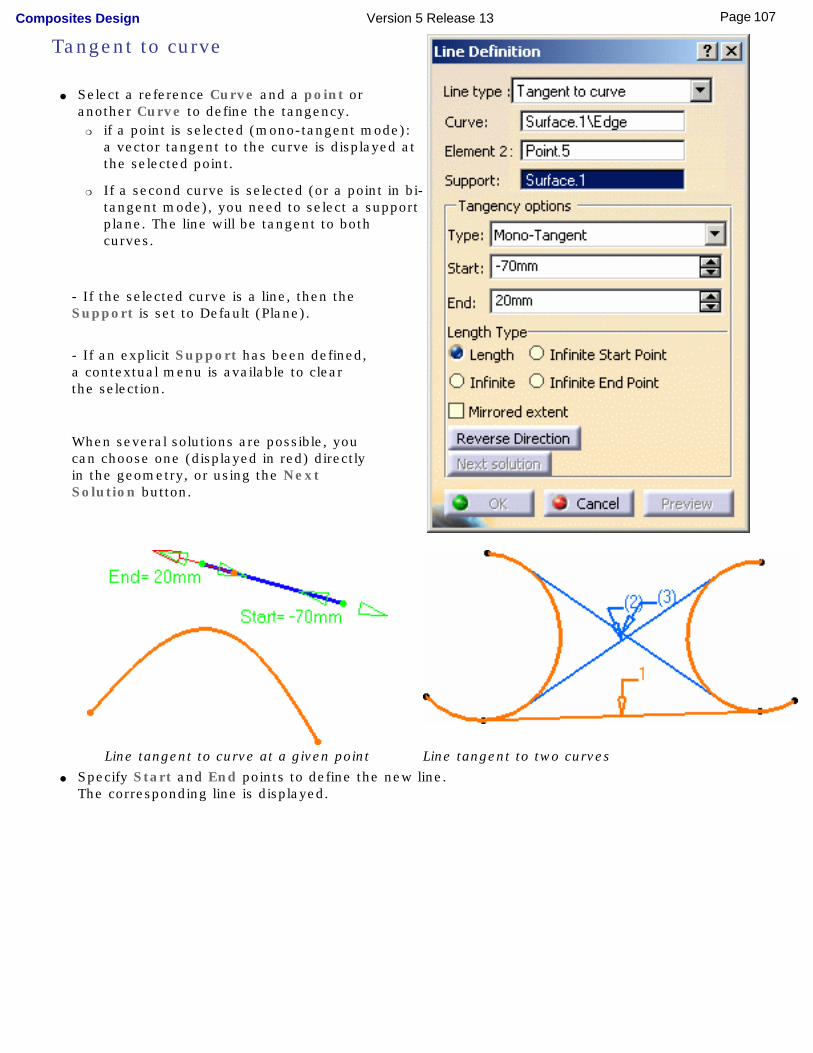
Tangent to curve
● Select a reference Curve and a point or another Curve to define the tangency.
❍ if a point is selected (mono-tangent mode): a vector tangent to the curve is displayed at the selected point.
❍ If a second curve is selected (or a point in bi-tangent mode), you need to select a support plane. The line will be tangent to both curves.
- If the selected curve is a line, then the Support is set to Default (Plane).
- If an explicit Support has been defined, a contextual menu is available to clear the selection.
When several solutions are possible, you can choose one (displayed in red) directly in the geometry, or using the Next Solution button.
Line tangent to curve at a given point Line tangent to two curves● Specify Start and End points to define the new line.
The corresponding line is displayed.
107Page Composites Design Version 5 Release 13
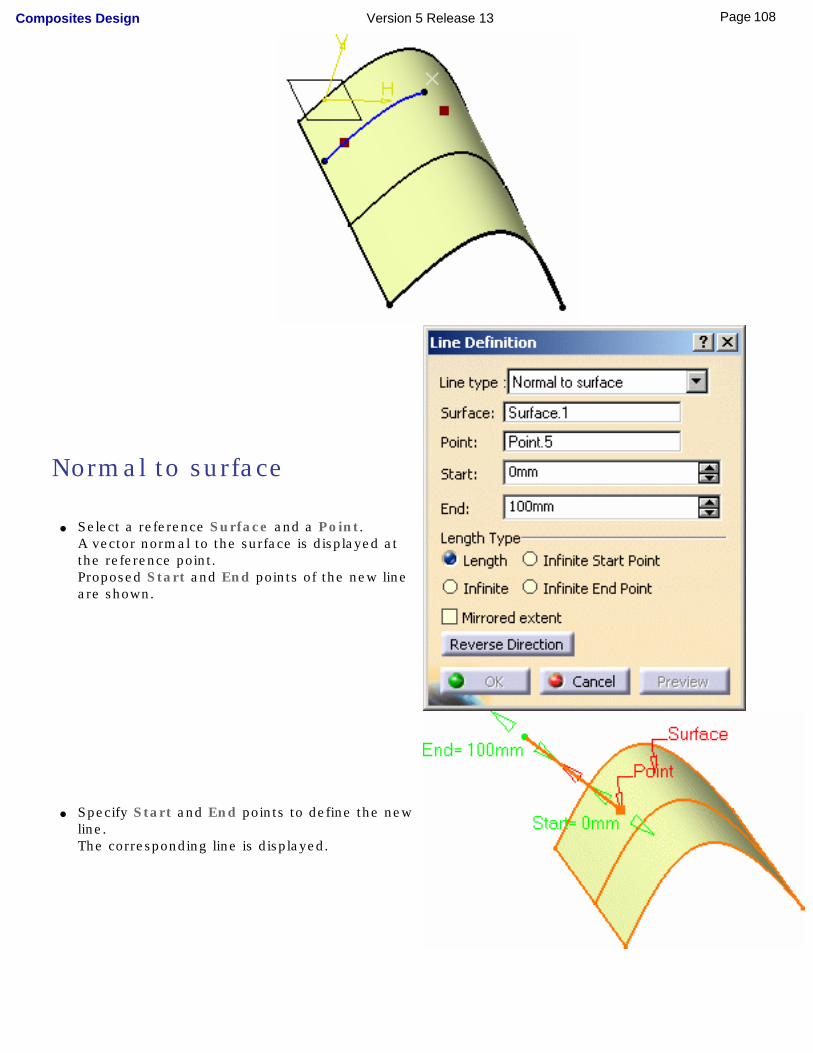
Normal to surface
● Select a reference Surface and a Point.A vector normal to the surface is displayed at the reference point. Proposed Start and End points of the new line are shown.
● Specify Start and End points to define the new line.The corresponding line is displayed.
108Page Composites Design Version 5 Release 13

Bisecting
● Select two lines. Their bisecting line is the line splitting in two equals parts the angle between these two lines.
● Select a point as the starting point for the line. By default it is the intersection of the bisecting line and the first selected line.
109Page Composites Design Version 5 Release 13
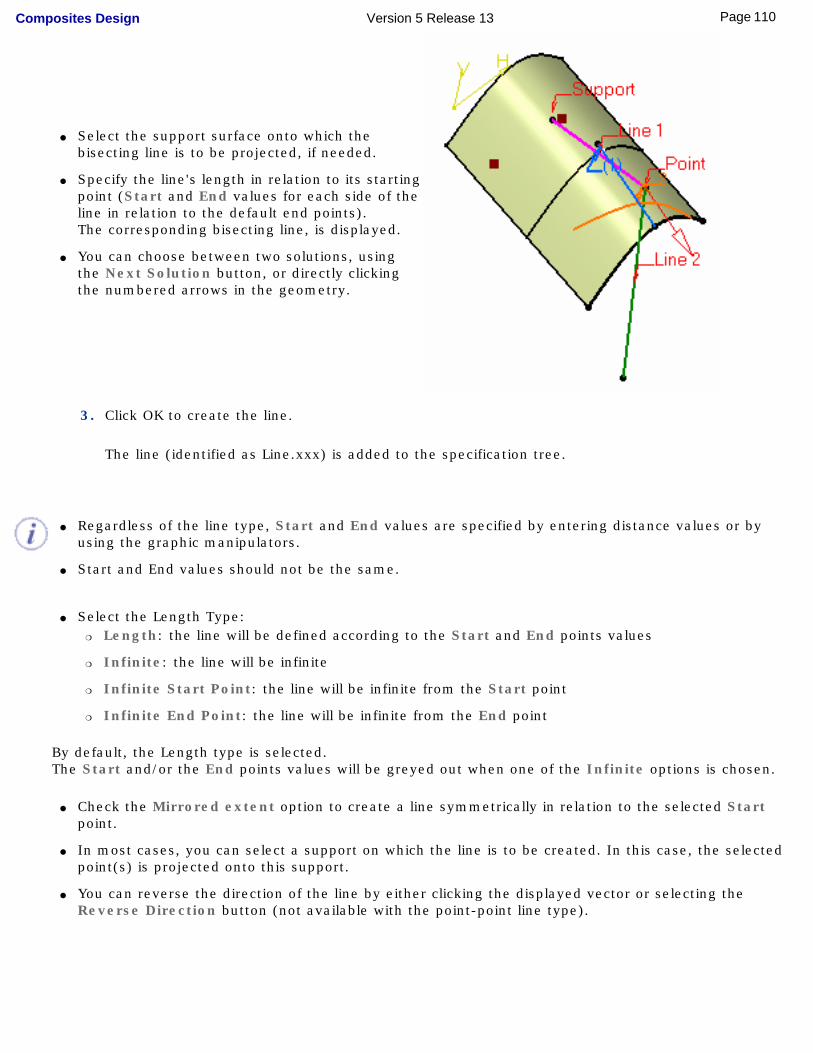
● Select the support surface onto which the bisecting line is to be projected, if needed.
● Specify the line's length in relation to its starting point (Start and End values for each side of the line in relation to the default end points).The corresponding bisecting line, is displayed.
● You can choose between two solutions, using the Next Solution button, or directly clicking the numbered arrows in the geometry.
3. Click OK to create the line.
The line (identified as Line.xxx) is added to the specification tree.
● Regardless of the line type, Start and End values are specified by entering distance values or by
using the graphic manipulators.
● Start and End values should not be the same.
● Select the Length Type: ❍ Length: the line will be defined according to the Start and End points values
❍ Infinite: the line will be infinite
❍ Infinite Start Point: the line will be infinite from the Start point
❍ Infinite End Point: the line will be infinite from the End point
By default, the Length type is selected.The Start and/or the End points values will be greyed out when one of the Infinite options is chosen.
● Check the Mirrored extent option to create a line symmetrically in relation to the selected Start
point.
● In most cases, you can select a support on which the line is to be created. In this case, the selected point(s) is projected onto this support.
● You can reverse the direction of the line by either clicking the displayed vector or selecting the Reverse Direction button (not available with the point-point line type).
110Page Composites Design Version 5 Release 13
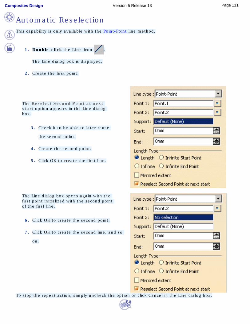
This capability is only available with the Point-Point line method.
1. Double-click the Line icon .
The Line dialog box is displayed.
2. Create the first point.
The Reselect Second Point at next start option appears in the Line dialog box.
3. Check it to be able to later reuse
the second point.
4. Create the second point.
5. Click OK to create the first line.
The Line dialog box opens again with the
first point initialized with the second point of the first line.
6. Click OK to create the second point.
7. Click OK to create the second line, and so
on.
To stop the repeat action, simply uncheck the option or click Cancel in the Line dialog box.
Automatic Reselection
111Page Composites Design Version 5 Release 13
CreatingPlanes
This task shows the various methods for creating planes:
● offset from a plane
● parallel through point
● angle/normal to a plane
● through three points
● through two lines
● through a point and a line
● through a planar curve
● normal to a curve
● tangent to a surface
● from its equation
● mean through points
Open the Planes1.CATPart document.
1. Click the Plane icon .
The Plane Definition dialog box appears.
2. Use the combo to choose the desired Plane type.
Once you have defined the plane, it is represented by a red square symbol, which you can move using the graphic manipulator.
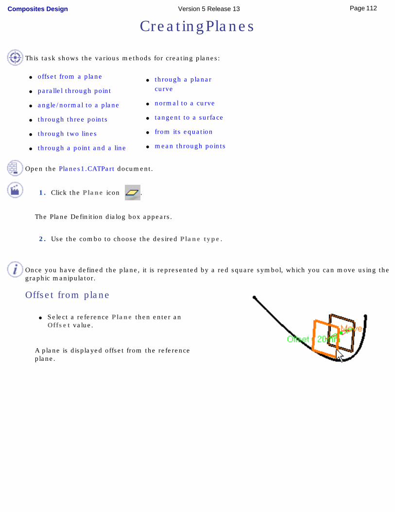
Offset from plane
● Select a reference Plane then enter an Offset value.
A plane is displayed offset from the reference plane.
112Page Composites Design Version 5 Release 13
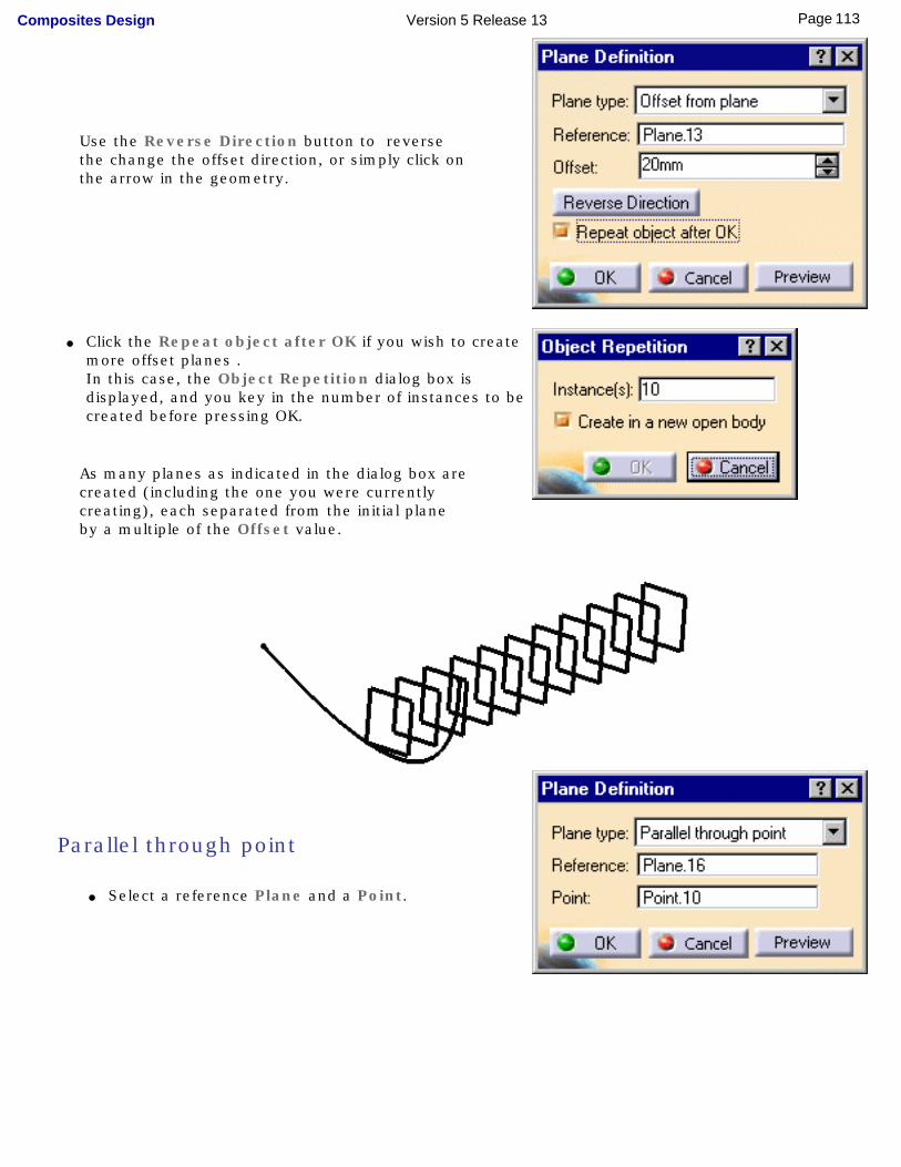
Use the Reverse Direction button to reverse the change the offset direction, or simply click on the arrow in the geometry.
● Click the Repeat object after OK if you wish to create
more offset planes . In this case, the Object Repetition dialog box is displayed, and you key in the number of instances to be created before pressing OK.
As many planes as indicated in the dialog box are created (including the one you were currently creating), each separated from the initial plane by a multiple of the Offset value.
Parallel through point
● Select a reference Plane and a Point.
113Page Composites Design Version 5 Release 13
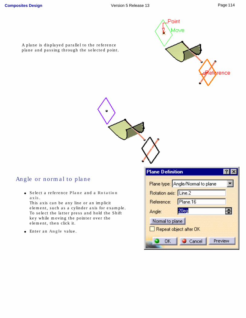
A plane is displayed parallel to the reference plane and passing through the selected point.
Angle or normal to plane
● Select a reference Plane and a Rotation axis.This axis can be any line or an implicit element, such as a cylinder axis for example. To select the latter press and hold the Shift key while moving the pointer over the element, then click it.
● Enter an Angle value.
114Page Composites Design Version 5 Release 13
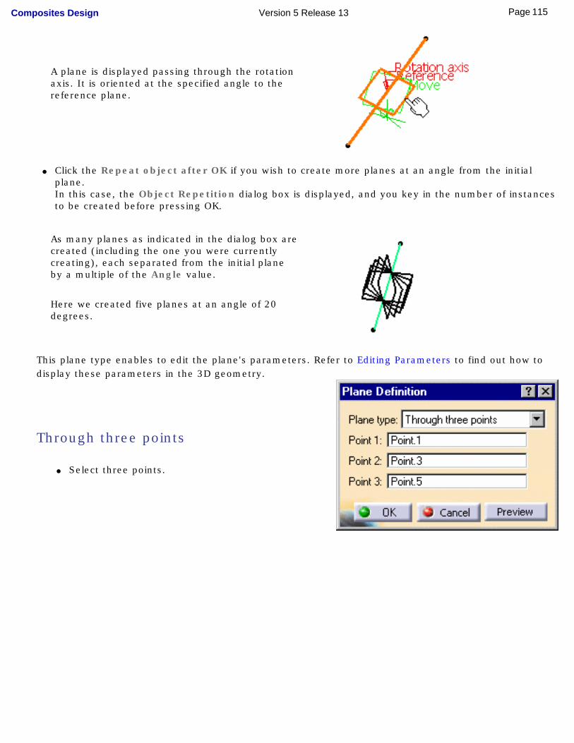
A plane is displayed passing through the rotation axis. It is oriented at the specified angle to the reference plane.
● Click the Repeat object after OK if you wish to create more planes at an angle from the initial plane. In this case, the Object Repetition dialog box is displayed, and you key in the number of instances to be created before pressing OK.
As many planes as indicated in the dialog box are created (including the one you were currently creating), each separated from the initial plane by a multiple of the Angle value.
Here we created five planes at an angle of 20 degrees.
This plane type enables to edit the plane's parameters. Refer to Editing Parameters to find out how to display these parameters in the 3D geometry.
Through three points
● Select three points.
115Page Composites Design Version 5 Release 13
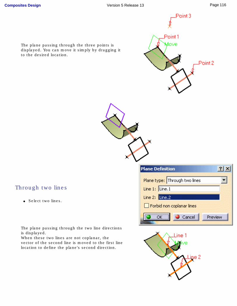
The plane passing through the three points is displayed. You can move it simply by dragging it to the desired location.
Through two lines
● Select two lines.
The plane passing through the two line directions is displayed.When these two lines are not coplanar, the vector of the second line is moved to the first line location to define the plane's second direction.
116Page Composites Design Version 5 Release 13
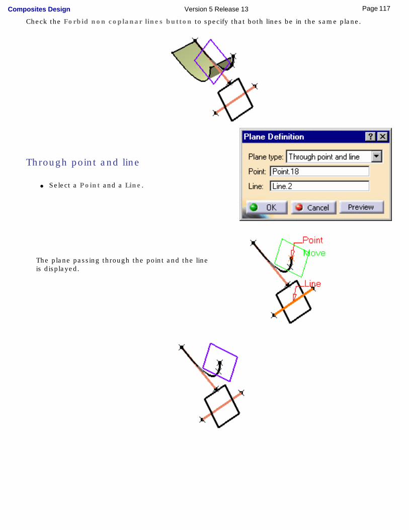
Check the Forbid non coplanar lines button to specify that both lines be in the same plane.
Through point and line
● Select a Point and a Line.
The plane passing through the point and the line is displayed.
117Page Composites Design Version 5 Release 13
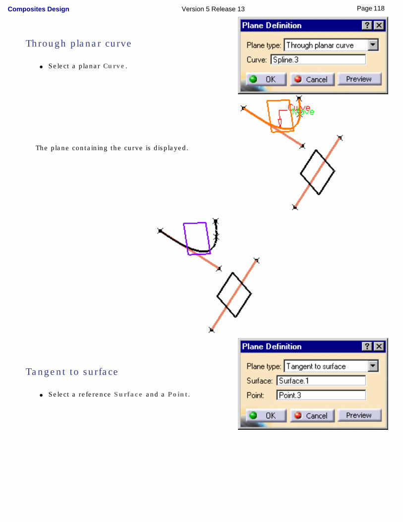
Through planar curve
● Select a planar Curve.
The plane containing the curve is displayed.
Tangent to surface
● Select a reference Surface and a Point.
118Page Composites Design Version 5 Release 13
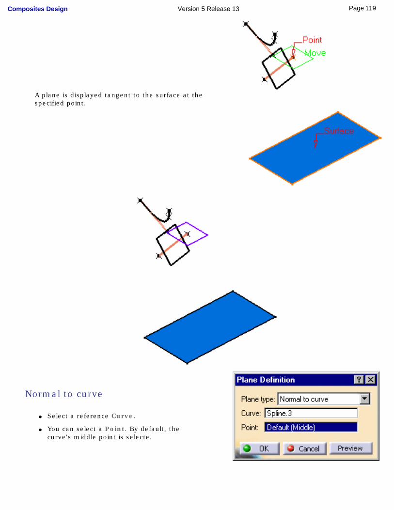
A plane is displayed tangent to the surface at the specified point.
Normal to curve
● Select a reference Curve.
● You can select a Point. By default, the curve's middle point is selecte.
119Page Composites Design Version 5 Release 13
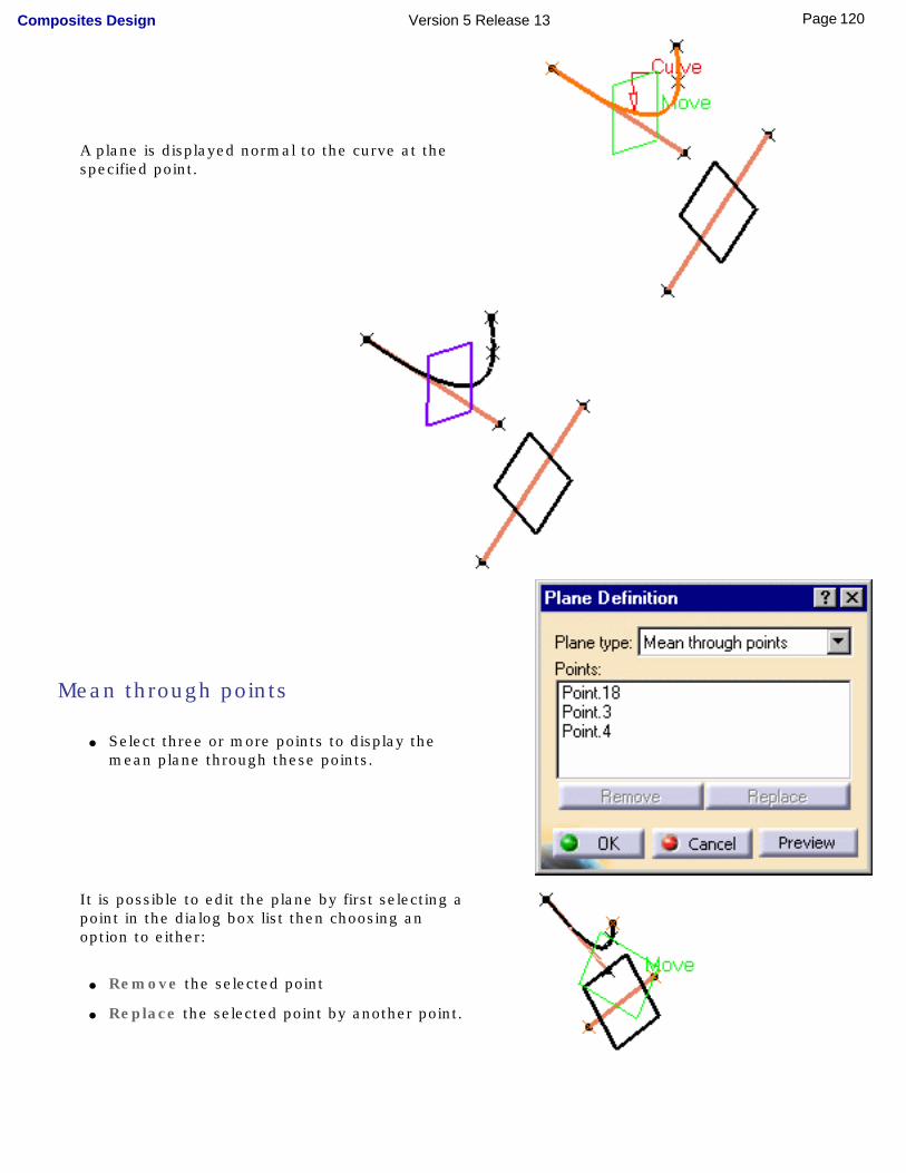
A plane is displayed normal to the curve at the specified point.
Mean through points
● Select three or more points to display the mean plane through these points.
It is possible to edit the plane by first selecting a point in the dialog box list then choosing an option to either:
● Remove the selected point
● Replace the selected point by another point.
120Page Composites Design Version 5 Release 13
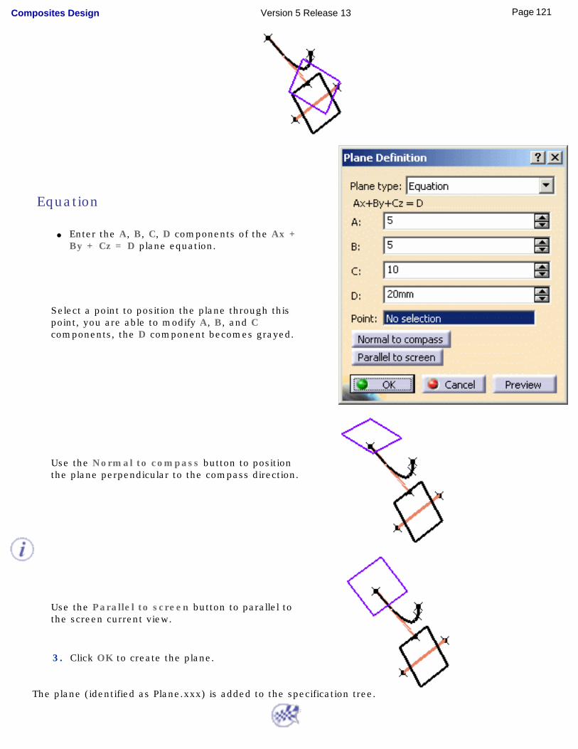
Equation
● Enter the A, B, C, D components of the Ax + By + Cz = D plane equation.
Select a point to position the plane through this point, you are able to modify A, B, and C components, the D component becomes grayed.
Use the Normal to compass button to position the plane perpendicular to the compass direction.
Use the Parallel to screen button to parallel to the screen current view.
3. Click OK to create the plane.
The plane (identified as Plane.xxx) is added to the specification tree.
121Page Composites Design Version 5 Release 13
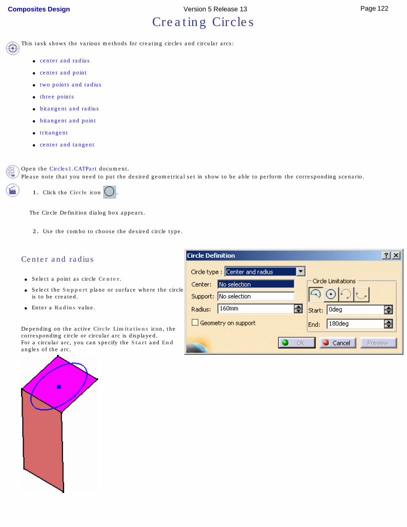
Creating Circles
This task shows the various methods for creating circles and circular arcs:
● center and radius
● center and point
● two points and radius
● three points
● bitangent and radius
● bitangent and point
● tritangent
● center and tangent
Open the Circles1.CATPart document.Please note that you need to put the desired geometrical set in show to be able to perform the corresponding scenario.
1. Click the Circle icon .
The Circle Definition dialog box appears.
2. Use the combo to choose the desired circle type.
Center and radius
● Select a point as circle Center.
● Select the Support plane or surface where the circle is to be created.
● Enter a Radius value.
Depending on the active Circle Limitations icon, the corresponding circle or circular arc is displayed.For a circular arc, you can specify the Start and End angles of the arc.
122Page Composites Design Version 5 Release 13
If a support surface is selected, the circle lies on the plane tangent to the surface at the selected point.
Start and End angles can be specified by entering values or by using the graphic manipulators.
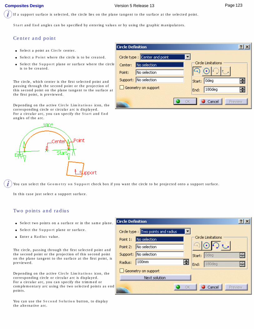
Center and point
● Select a point as Circle center.
● Select a Point where the circle is to be created.
● Select the Support plane or surface where the circle is to be created.
The circle, which center is the first selected point and passing through the second point or the projection of this second point on the plane tangent to the surface at the first point, is previewed.
Depending on the active Circle Limitations icon, the corresponding circle or circular arc is displayed.For a circular arc, you can specify the Start and End angles of the arc.
You can select the Geometry on Support check box if you want the circle to be projected onto a support surface.
In this case just select a support surface.
Two points and radius
● Select two points on a surface or in the same plane.
● Select the Support plane or surface.
● Enter a Radius value.
The circle, passing through the first selected point and the second point or the projection of this second point on the plane tangent to the surface at the first point, is previewed.
Depending on the active Circle Limitations icon, the corresponding circle or circular arc is displayed. For a circular arc, you can specify the trimmed or complementary arc using the two selected points as end points.
You can use the Second Solution button, to display the alternative arc.
123Page Composites Design Version 5 Release 13
You can select the Geometry on Support check box if you want the circle to be projected onto a support surface.
In this case just select a support surface.
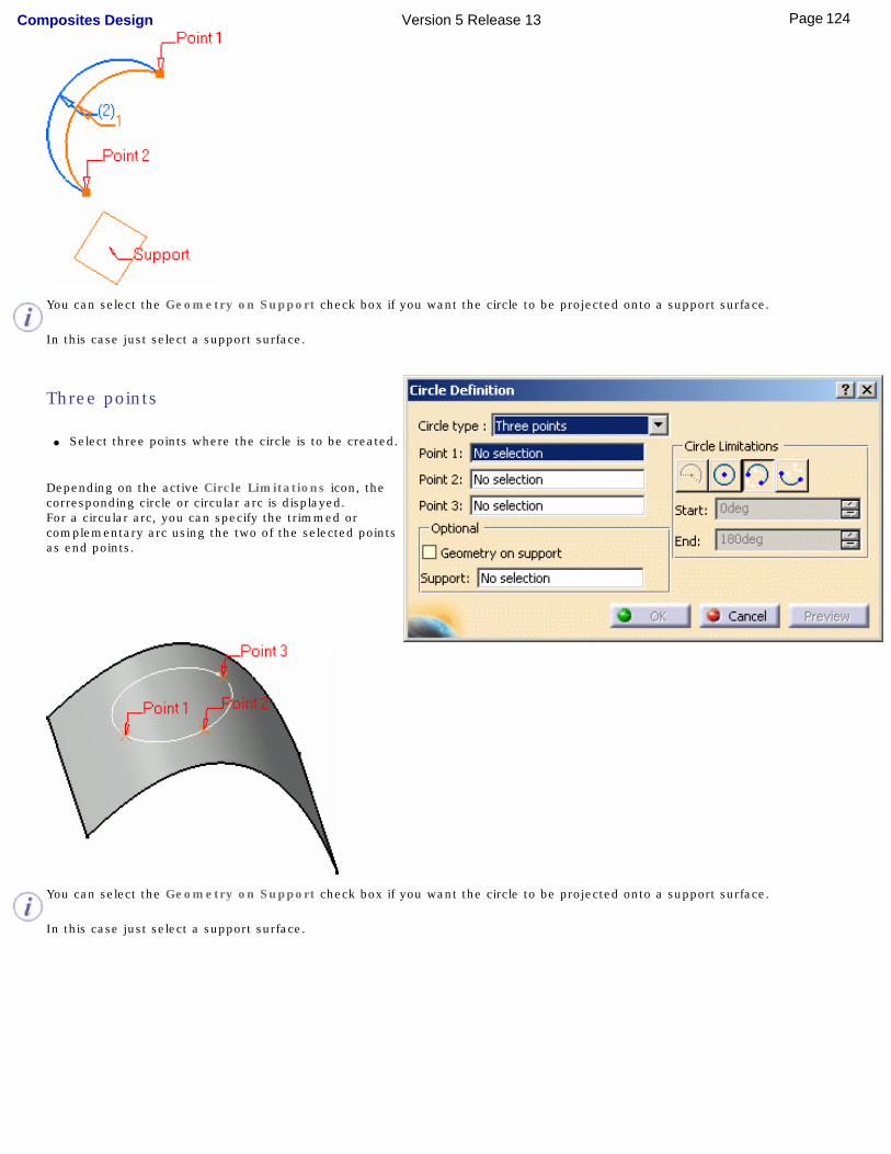
Three points
● Select three points where the circle is to be created.
Depending on the active Circle Limitations icon, the corresponding circle or circular arc is displayed. For a circular arc, you can specify the trimmed or complementary arc using the two of the selected points as end points.
You can select the Geometry on Support check box if you want the circle to be projected onto a support surface.
In this case just select a support surface.
124Page Composites Design Version 5 Release 13
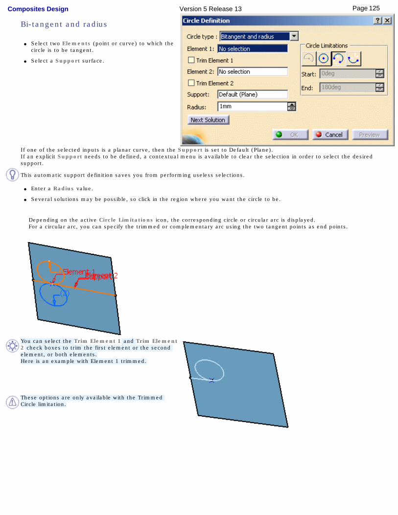
Bi-tangent and radius
● Select two Elements (point or curve) to which the circle is to be tangent.
● Select a Support surface.
If one of the selected inputs is a planar curve, then the Support is set to Default (Plane).If an explicit Support needs to be defined, a contextual menu is available to clear the selection in order to select the desired support.
This automatic support definition saves you from performing useless selections.
● Enter a Radius value.
● Several solutions may be possible, so click in the region where you want the circle to be.
Depending on the active Circle Limitations icon, the corresponding circle or circular arc is displayed. For a circular arc, you can specify the trimmed or complementary arc using the two tangent points as end points.
You can select the Trim Element 1 and Trim Element 2 check boxes to trim the first element or the second element, or both elements.Here is an example with Element 1 trimmed.
These options are only available with the Trimmed Circle limitation.
125Page Composites Design Version 5 Release 13
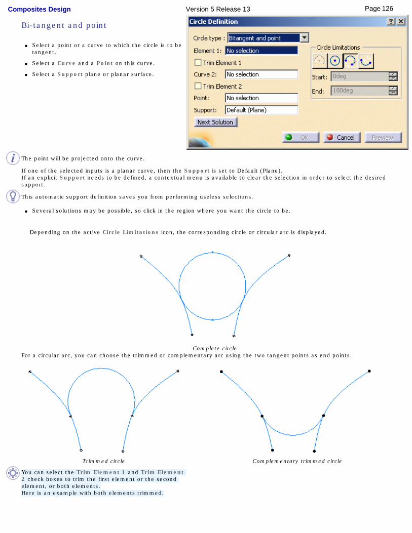
Bi-tangent and point
● Select a point or a curve to which the circle is to be tangent.
● Select a Curve and a Point on this curve.
● Select a Support plane or planar surface.
The point will be projected onto the curve.
If one of the selected inputs is a planar curve, then the Support is set to Default (Plane).If an explicit Support needs to be defined, a contextual menu is available to clear the selection in order to select the desired support.
This automatic support definition saves you from performing useless selections.
● Several solutions may be possible, so click in the region where you want the circle to be.
Depending on the active Circle Limitations icon, the corresponding circle or circular arc is displayed.
Complete circleFor a circular arc, you can choose the trimmed or complementary arc using the two tangent points as end points.
Trimmed circle Complementary trimmed circle
You can select the Trim Element 1 and Trim Element 2 check boxes to trim the first element or the second element, or both elements.Here is an example with both elements trimmed.
126Page Composites Design Version 5 Release 13
These options are only available with the Trimmed Circle limitation.
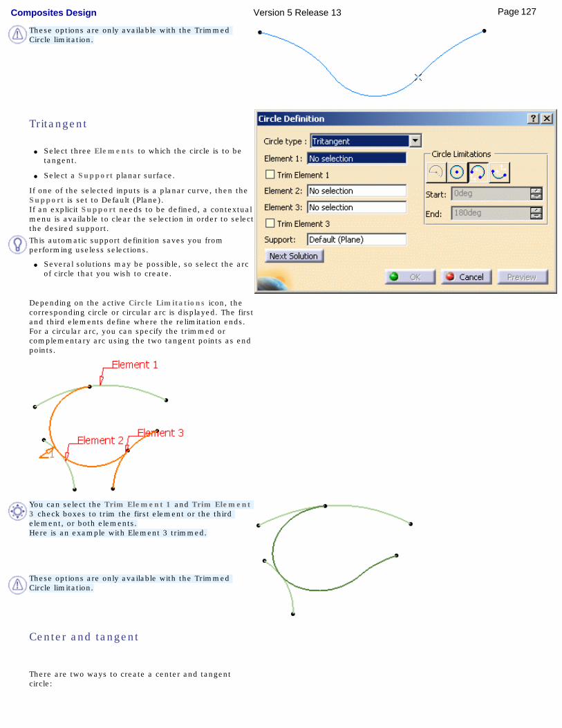
Tritangent
● Select three Elements to which the circle is to be tangent.
● Select a Support planar surface.
If one of the selected inputs is a planar curve, then the Support is set to Default (Plane).If an explicit Support needs to be defined, a contextual menu is available to clear the selection in order to select the desired support.
This automatic support definition saves you from performing useless selections.
● Several solutions may be possible, so select the arc
of circle that you wish to create.
Depending on the active Circle Limitations icon, the corresponding circle or circular arc is displayed. The first and third elements define where the relimitation ends. For a circular arc, you can specify the trimmed or complementary arc using the two tangent points as end points.
You can select the Trim Element 1 and Trim Element 3 check boxes to trim the first element or the third element, or both elements.Here is an example with Element 3 trimmed.
These options are only available with the Trimmed Circle limitation.
Center and tangent
There are two ways to create a center and tangent circle:
127Page Composites Design Version 5 Release 13
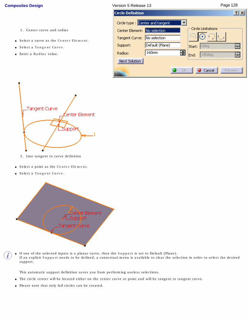
1. Center curve and radius
● Select a curve as the Center Element.
● Select a Tangent Curve.
● Enter a Radius value.
2. Line tangent to curve definition
● Select a point as the Center Element.
● Select a Tangent Curve.
● If one of the selected inputs is a planar curve, then the Support is set to Default (Plane).If an explicit Support needs to be defined, a contextual menu is available to clear the selection in order to select the desired support.
This automatic support definition saves you from performing useless selections.
● The circle center will be located either on the center curve or point and will be tangent to tangent curve.
● Please note that only full circles can be created.
128Page Composites Design Version 5 Release 13

4. Click OK to create the circle or circular arc.
The circle (identified as Circle.xxx) is added to the specification tree.When several solutions are possible, click the Next Solution button to move to another arc of circle, or directly select the arc you want in the 3D geometry.
A circle may have several points as center if the selected element is made of various circle arcs with different centers.
Parameters can be edited in the 3D geometry. To have further information, please refer to the Editing Parameters chapter.
129Page Composites Design Version 5 Release 13

Interoperability With Generative Shape DesignJoining Geometry
[
130Page Composites Design Version 5 Release 13
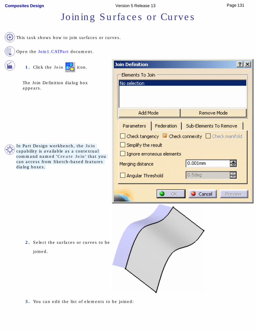
Joining Surfaces or Curves
This task shows how to join surfaces or curves.
Open the Join1.CATPart document.
1. Click the Join icon.
The Join Definition dialog box appears.
In Part Design workbench, the Join capability is available as a contextual command named 'Create Join' that you can access from Sketch-based features dialog boxes.
2. Select the surfaces or curves to be
joined.
3. You can edit the list of elements to be joined:
131Page Composites Design Version 5 Release 13
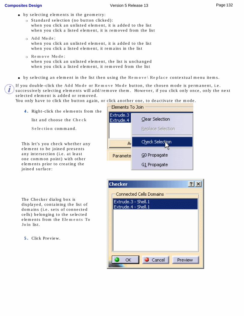
● by selecting elements in the geometry: ❍ Standard selection (no button clicked):
when you click an unlisted element, it is added to the list when you click a listed element, it is removed from the list
❍ Add Mode: when you click an unlisted element, it is added to the list when you click a listed element, it remains in the list
❍ Remove Mode: when you click an unlisted element, the list is unchanged when you click a listed element, it removed from the list
● by selecting an element in the list then using the Remove\Replace contextual menu items.
If you double-click the Add Mode or Remove Mode button, the chosen mode is permanent, i.e. successively selecting elements will add/remove them. However, if you click only once, only the next selected element is added or removed.You only have to click the button again, or click another one, to deactivate the mode.
4. Right-click the elements from the
list and choose the Check
Selection command.
This let's you check whether any element to be joined presents any intersection (i.e. at least one common point) with other elements prior to creating the joined surface:
The Checker dialog box is displayed, containing the list of domains (i.e. sets of connected cells) belonging to the selected elements from the Elements To Join list.
5. Click Preview.
132Page Composites Design Version 5 Release 13
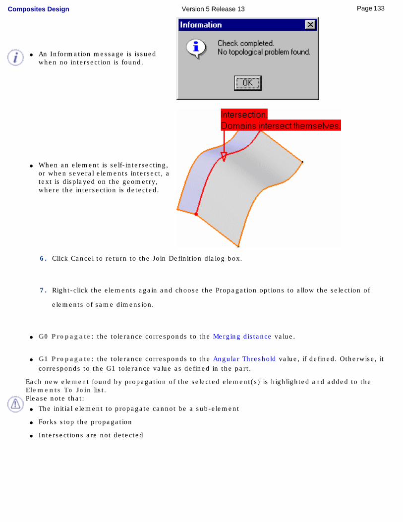
● An Information message is issued when no intersection is found.
● When an element is self-intersecting, or when several elements intersect, a text is displayed on the geometry, where the intersection is detected.
6. Click Cancel to return to the Join Definition dialog box.
7. Right-click the elements again and choose the Propagation options to allow the selection of
elements of same dimension.
● G0 Propagate: the tolerance corresponds to the Merging distance value.
● G1 Propagate: the tolerance corresponds to the Angular Threshold value, if defined. Otherwise, it corresponds to the G1 tolerance value as defined in the part.
Each new element found by propagation of the selected element(s) is highlighted and added to the Elements To Join list.Please note that:
● The initial element to propagate cannot be a sub-element
● Forks stop the propagation
● Intersections are not detected
133Page Composites Design Version 5 Release 13
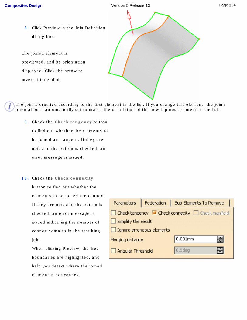
8. Click Preview in the Join Definition
dialog box.
The joined element is
previewed, and its orientation
displayed. Click the arrow to
invert it if needed.
The join is oriented according to the first element in the list. If you change this element, the join's orientation is automatically set to match the orientation of the new topmost element in the list.
9. Check the Check tangency button
to find out whether the elements to
be joined are tangent. If they are
not, and the button is checked, an
error message is issued.
10. Check the Check connexity
button to find out whether the
elements to be joined are connex.
If they are not, and the button is
checked, an error message is
issued indicating the number of
connex domains in the resulting
join.
When clicking Preview, the free
boundaries are highlighted, and
help you detect where the joined
element is not connex.
134Page Composites Design Version 5 Release 13
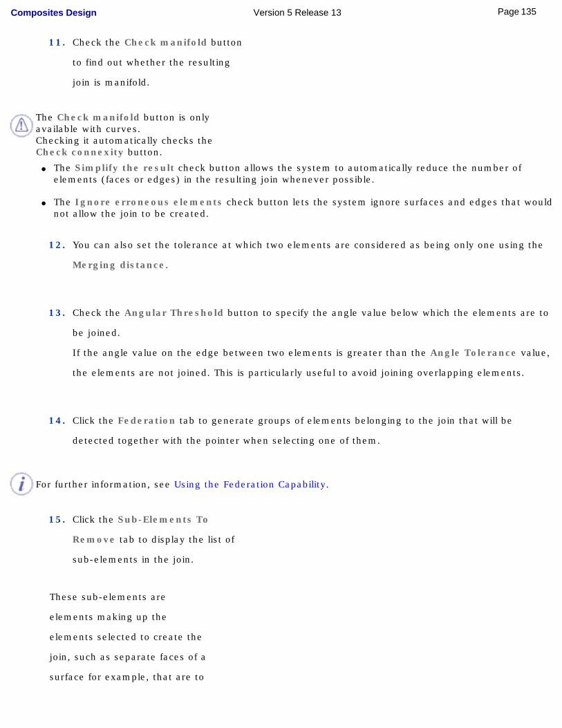
11. Check the Check manifold button
to find out whether the resulting
join is manifold.
The Check manifold button is only available with curves.Checking it automatically checks the Check connexity button.
● The Simplify the result check button allows the system to automatically reduce the number of elements (faces or edges) in the resulting join whenever possible.
● The Ignore erroneous elements check button lets the system ignore surfaces and edges that would not allow the join to be created.
12. You can also set the tolerance at which two elements are considered as being only one using the
Merging distance.
13. Check the Angular Threshold button to specify the angle value below which the elements are to
be joined.
If the angle value on the edge between two elements is greater than the Angle Tolerance value,
the elements are not joined. This is particularly useful to avoid joining overlapping elements.
14. Click the Federation tab to generate groups of elements belonging to the join that will be
detected together with the pointer when selecting one of them.
For further information, see Using the Federation Capability.
15. Click the Sub-Elements To
Remove tab to display the list of
sub-elements in the join.
These sub-elements are
elements making up the
elements selected to create the
join, such as separate faces of a
surface for example, that are to
135Page Composites Design Version 5 Release 13
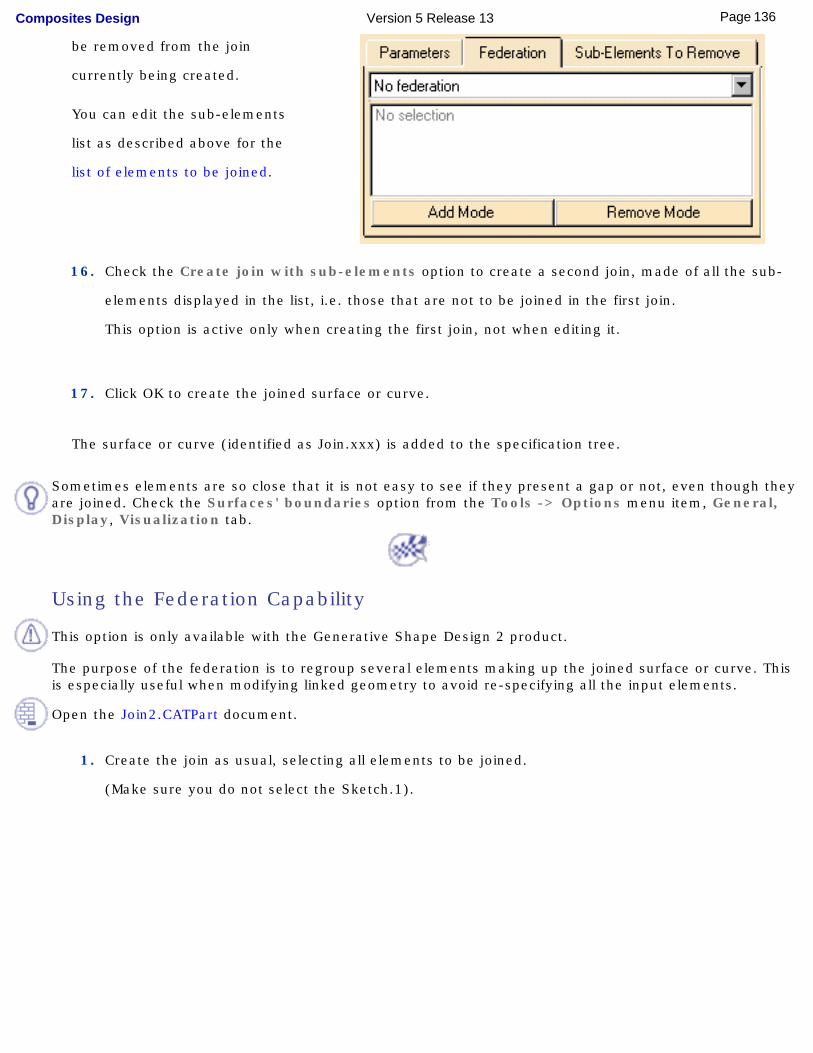
be removed from the join
currently being created.
You can edit the sub-elements
list as described above for the
list of elements to be joined.
16. Check the Create join with sub-elements option to create a second join, made of all the sub-
elements displayed in the list, i.e. those that are not to be joined in the first join.
This option is active only when creating the first join, not when editing it.
17. Click OK to create the joined surface or curve.
The surface or curve (identified as Join.xxx) is added to the specification tree.
Sometimes elements are so close that it is not easy to see if they present a gap or not, even though they are joined. Check the Surfaces' boundaries option from the Tools -> Options menu item, General, Display, Visualization tab.
Using the Federation Capability
This option is only available with the Generative Shape Design 2 product.
The purpose of the federation is to regroup several elements making up the joined surface or curve. This is especially useful when modifying linked geometry to avoid re-specifying all the input elements.
Open the Join2.CATPart document.
1. Create the join as usual, selecting all elements to be joined.
(Make sure you do not select the Sketch.1).
136Page Composites Design Version 5 Release 13
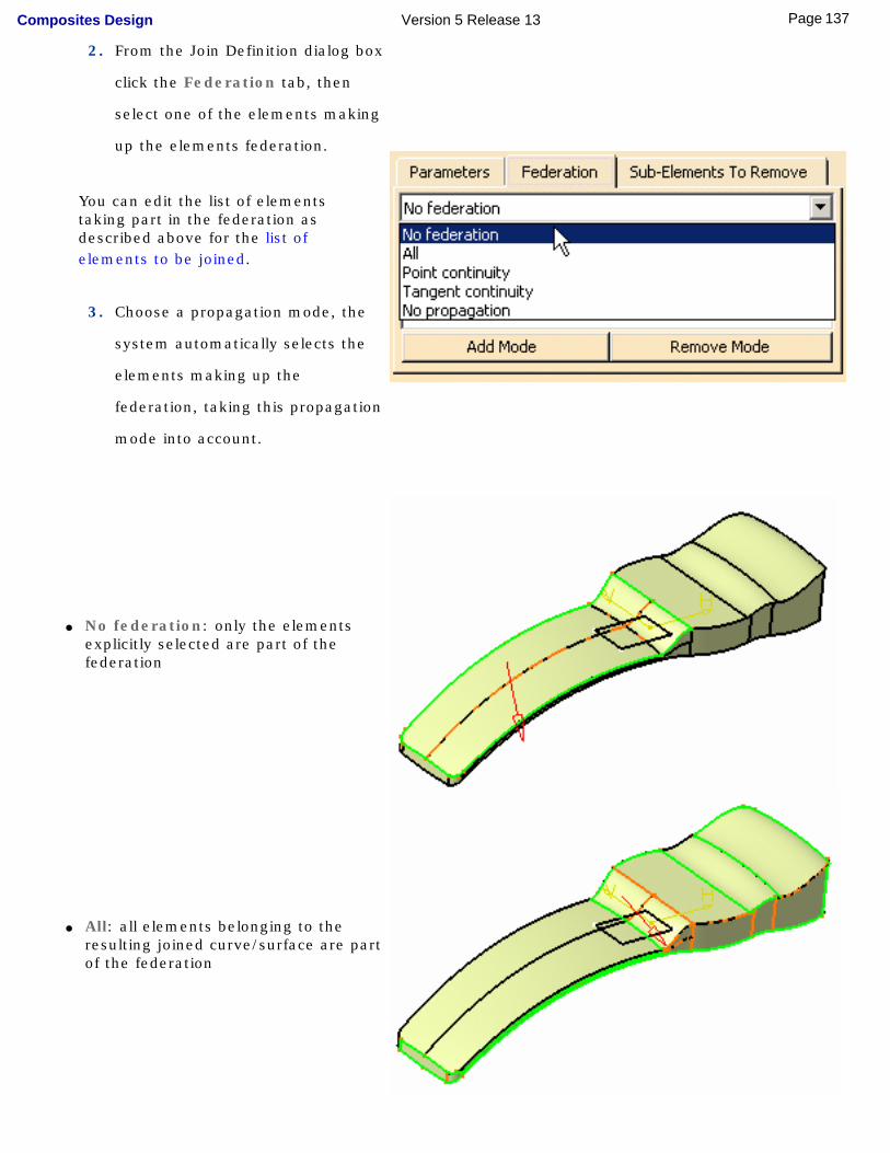
2. From the Join Definition dialog box
click the Federation tab, then
select one of the elements making
up the elements federation.
You can edit the list of elements taking part in the federation as described above for the list of elements to be joined.
3. Choose a propagation mode, the
system automatically selects the
elements making up the
federation, taking this propagation
mode into account.
● No federation: only the elements explicitly selected are part of the federation
● All: all elements belonging to the resulting joined curve/surface are part of the federation
137Page Composites Design Version 5 Release 13
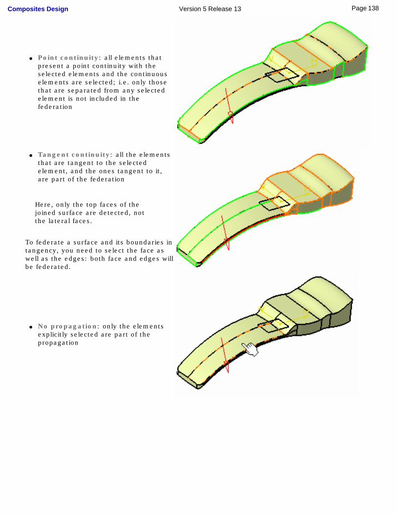
● Point continuity: all elements that present a point continuity with the selected elements and the continuous elements are selected; i.e. only those that are separated from any selected element is not included in the federation
● Tangent continuity: all the elements that are tangent to the selected element, and the ones tangent to it, are part of the federation
Here, only the top faces of the joined surface are detected, not the lateral faces.
To federate a surface and its boundaries in tangency, you need to select the face as well as the edges: both face and edges will be federated.
● No propagation: only the elements
explicitly selected are part of the propagation
138Page Composites Design Version 5 Release 13
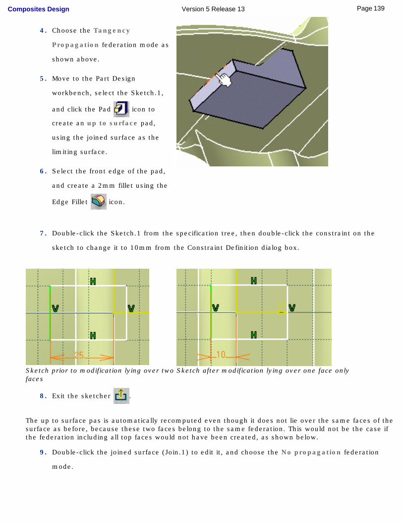
4. Choose the Tangency
Propagation federation mode as
shown above.
5. Move to the Part Design
workbench, select the Sketch.1,
and click the Pad icon to
create an up to surface pad,
using the joined surface as the
limiting surface.
6. Select the front edge of the pad,
and create a 2mm fillet using the
Edge Fillet icon.
7. Double-click the Sketch.1 from the specification tree, then double-click the constraint on the
sketch to change it to 10mm from the Constraint Definition dialog box.
Sketch prior to modification lying over two faces
Sketch after modification lying over one face only
8. Exit the sketcher .
The up to surface pas is automatically recomputed even though it does not lie over the same faces of the surface as before, because these two faces belong to the same federation. This would not be the case if the federation including all top faces would not have been created, as shown below.
9. Double-click the joined surface (Join.1) to edit it, and choose the No propagation federation
mode.
139Page Composites Design Version 5 Release 13
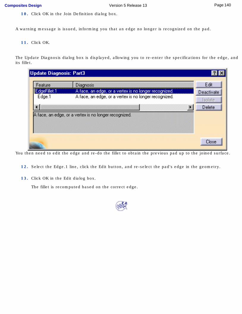
10. Click OK in the Join Definition dialog box.
A warning message is issued, informing you that an edge no longer is recognized on the pad.
11. Click OK.
The Update Diagnosis dialog box is displayed, allowing you to re-enter the specifications for the edge, and its fillet.
You then need to edit the edge and re-do the fillet to obtain the previous pad up to the joined surface.
12. Select the Edge.1 line, click the Edit button, and re-select the pad's edge in the geometry.
13. Click OK in the Edit dialog box.
The fillet is recomputed based on the correct edge.
140Page Composites Design Version 5 Release 13
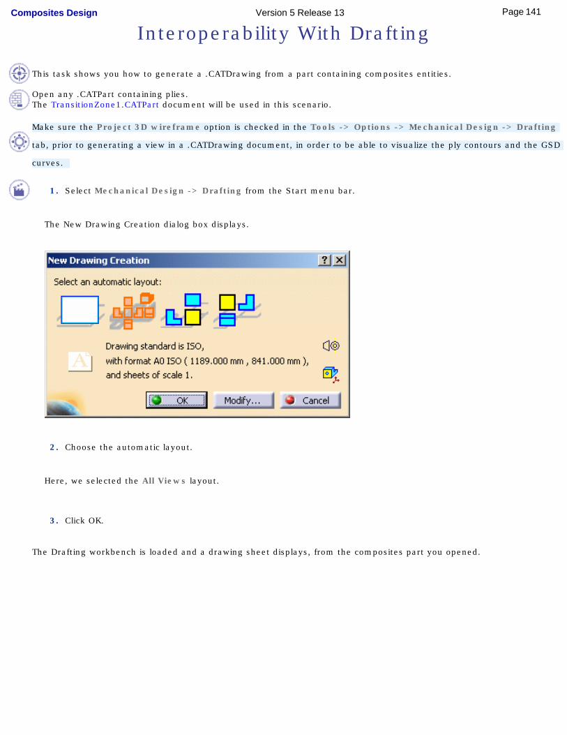
Interoperability With Drafting
This task shows you how to generate a .CATDrawing from a part containing composites entities.
Open any .CATPart containing plies.The TransitionZone1.CATPart document will be used in this scenario.
Make sure the Project 3D wireframe option is checked in the Tools -> Options -> Mechanical Design -> Drafting
tab, prior to generating a view in a .CATDrawing document, in order to be able to visualize the ply contours and the GSD
curves.
1. Select Mechanical Design -> Drafting from the Start menu bar.
The New Drawing Creation dialog box displays.
2. Choose the automatic layout.
Here, we selected the All Views layout.
3. Click OK.
The Drafting workbench is loaded and a drawing sheet displays, from the composites part you opened.
141Page Composites Design Version 5 Release 13
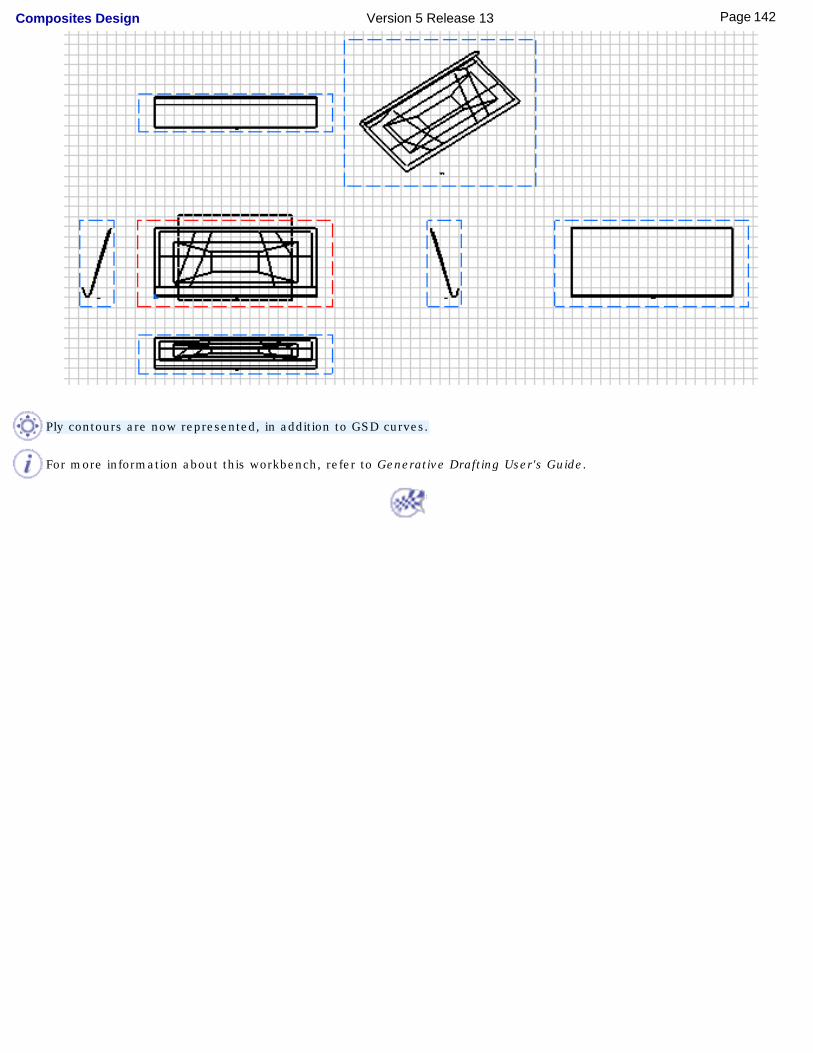
Ply contours are now represented, in addition to GSD curves.
For more information about this workbench, refer to Generative Drafting User's Guide.
142Page Composites Design Version 5 Release 13

Composites InteroperabilityOptimal CATIA PLM Usability for Composites Design
143Page Composites Design Version 5 Release 13
Optimal CATIA PLM Usability for Composites Design
When working with ENOVIA V5, the safe save mode ensures that you only create data in CATIA that can be correctly saved in ENOVIA. Therefore, in interoperability mode, some CATIA V5 commands are grayed out / hidden in the Composites Design workbench.
ENOVIA V5 offers two different storage modes: Workpackage (Document kept - Publications Exposed) and Explode (Document not kept).
In Composites Design workbench, when saving data into ENOVIA V5, the global transaction is guaranteed (both in Workpackage and Explode modes). All FreeStyle commands are thus available at all times.
To ensure seamless integration, you must have both a CATIA and ENOVIA session running.
For more information on the Safe Save mode, refer to "How to do a Safe Save in ENOVIA LCA from CATIA V5" in the Version 5 ENOVIA-CATIA Interoperability User's Guide.
144Page Composites Design Version 5 Release 13
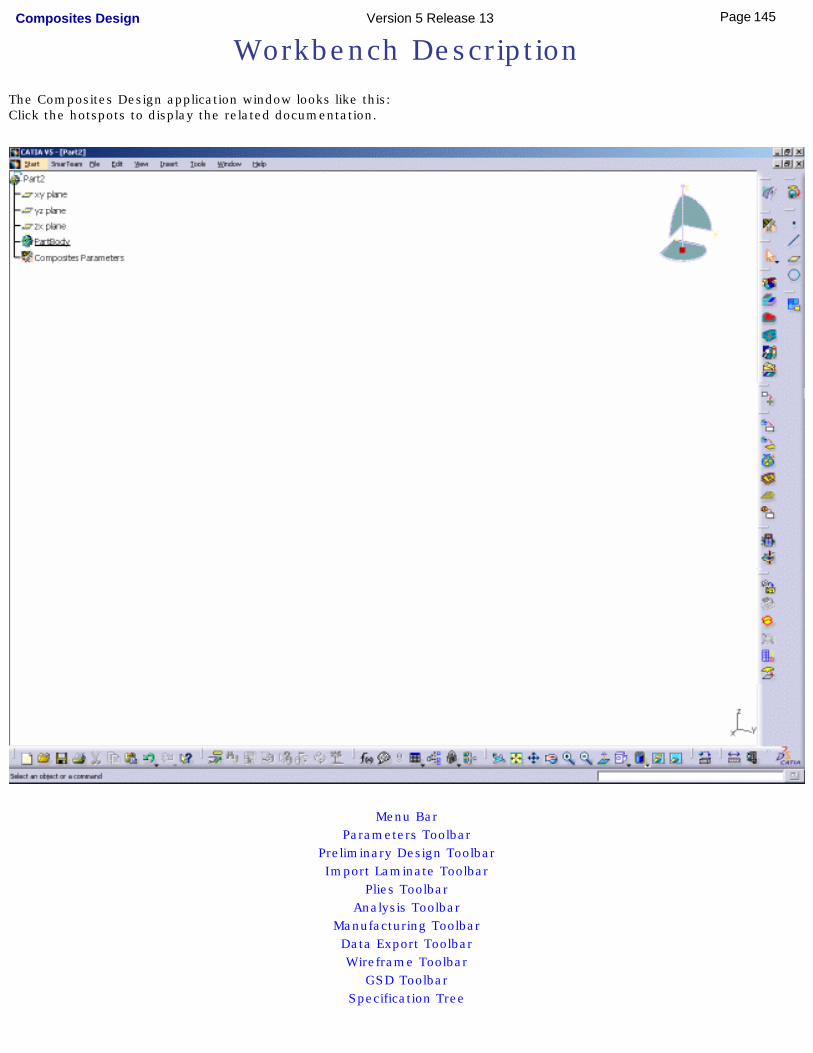
Workbench DescriptionThe Composites Design application window looks like this:Click the hotspots to display the related documentation.
Menu BarParameters Toolbar
Preliminary Design ToolbarImport Laminate Toolbar
Plies ToolbarAnalysis Toolbar
Manufacturing ToolbarData Export ToolbarWireframe Toolbar
GSD ToolbarSpecification Tree
145Page Composites Design Version 5 Release 13
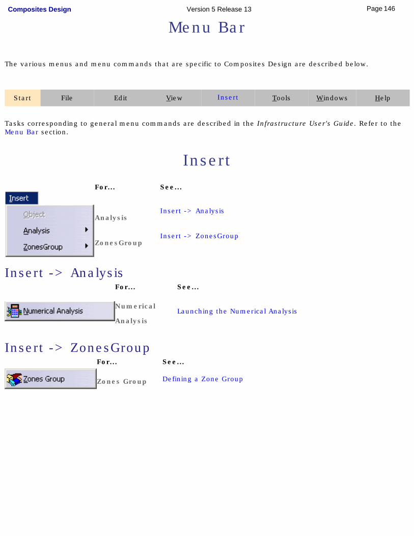
Menu Bar
The various menus and menu commands that are specific to Composites Design are described below.
Start File Edit View Insert Tools Windows Help
Tasks corresponding to general menu commands are described in the Infrastructure User's Guide. Refer to the Menu Bar section.
Insert For... See...
AnalysisInsert -> Analysis
ZonesGroupInsert -> ZonesGroup
Insert -> AnalysisFor... See...
Numerical
AnalysisLaunching the Numerical Analysis
Insert -> ZonesGroupFor... See...
Zones Group Defining a Zone Group
[ ]
146Page Composites Design Version 5 Release 13
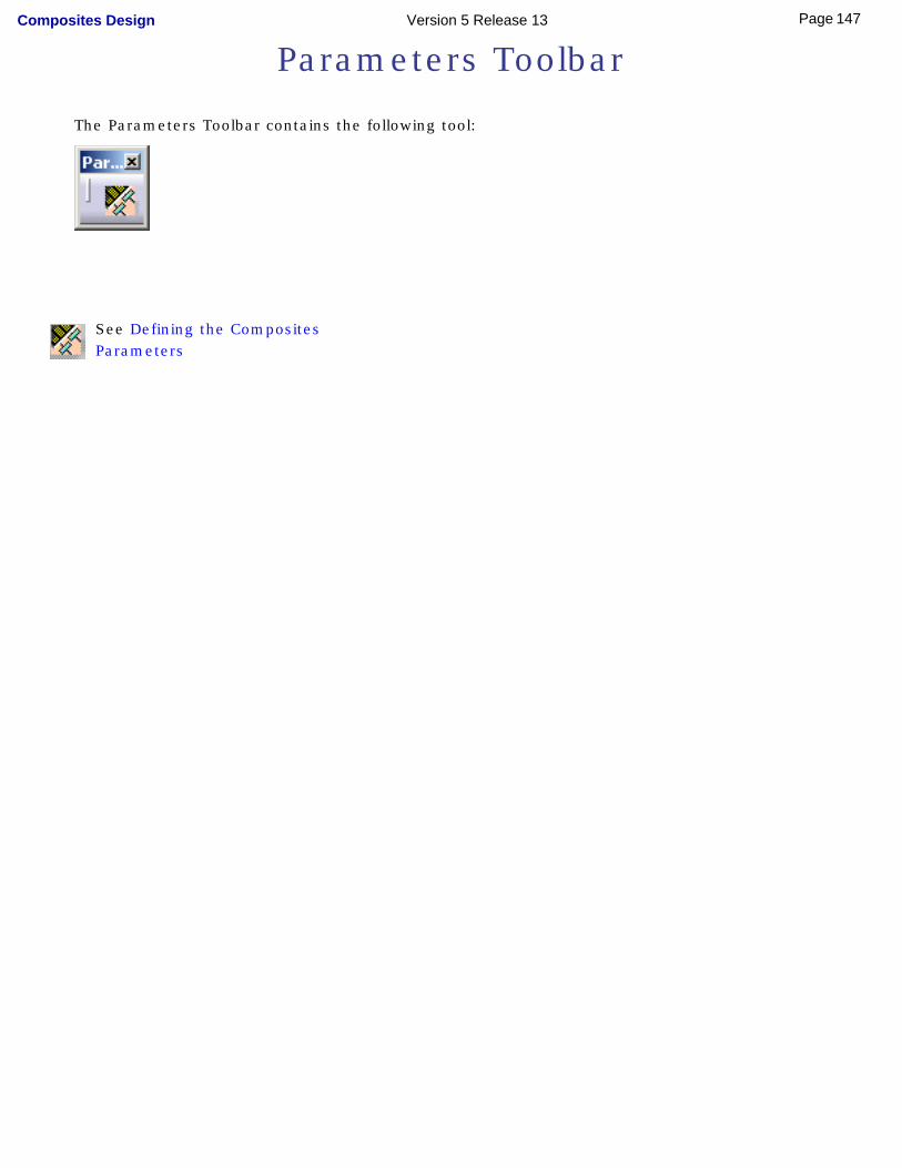
Parameters Toolbar
The Parameters Toolbar contains the following tool:
See Defining the Composites Parameters
[
147Page Composites Design Version 5 Release 13
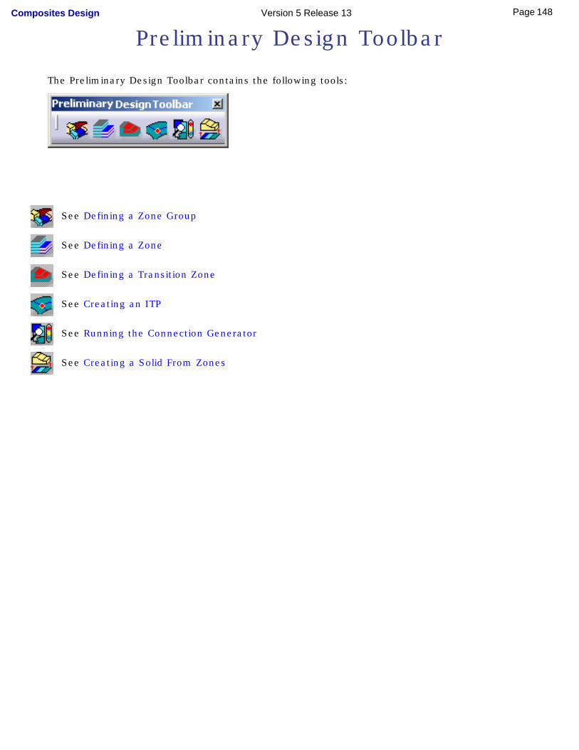
Preliminary Design Toolbar
The Preliminary Design Toolbar contains the following tools:
See Defining a Zone Group
See Defining a Zone
See Defining a Transition Zone
See Creating an ITP
See Running the Connection Generator
See Creating a Solid From Zones
[ ]
148Page Composites Design Version 5 Release 13
Import Laminate Toolbar
The Import Laminate Toolbar contains the following tool:
See Importing a Laminate
[ ]
149Page Composites Design Version 5 Release 13
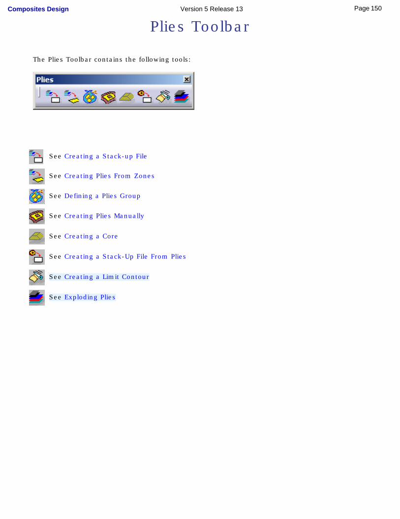
Plies Toolbar
The Plies Toolbar contains the following tools:
See Creating a Stack-up File
See Creating Plies From Zones
See Defining a Plies Group
See Creating Plies Manually
See Creating a Core
See Creating a Stack-Up File From Plies
See Creating a Limit Contour
See Exploding Plies
[
150Page Composites Design Version 5 Release 13

Analysis Toolbar
The Analysis Toolbar contains the following tools:
See Launching the Numerical Analysis
See Creating a Core Sampling
[ ]
151Page Composites Design Version 5 Release 13
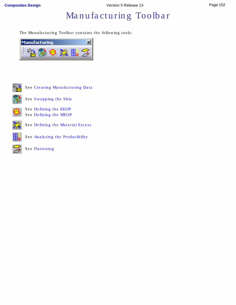
Manufacturing Toolbar
The Manufacturing Toolbar contains the following tools:
See Creating Manufacturing Data
See Swapping the Skin
See Defining the EEOPSee Defining the MEOP
See Defining the Material Excess
See Analyzing the Producibility
See Flattening
[
152Page Composites Design Version 5 Release 13
Data Export Toolbar
The Data Export Toolbar contains the following tool:
See Exporting Ply Data
[
153Page Composites Design Version 5 Release 13
Wireframe Toolbar
The Wireframe Toolbar contains the following tools:
See Creating Points
See Creating Lines
See Creating Planes
See Creating Circles
[
154Page Composites Design Version 5 Release 13
GSD Toolbar
The GSD Toolbar contains the following tool:
See Interoperability With Generative Shape Design
[ ]
155Page Composites Design Version 5 Release 13
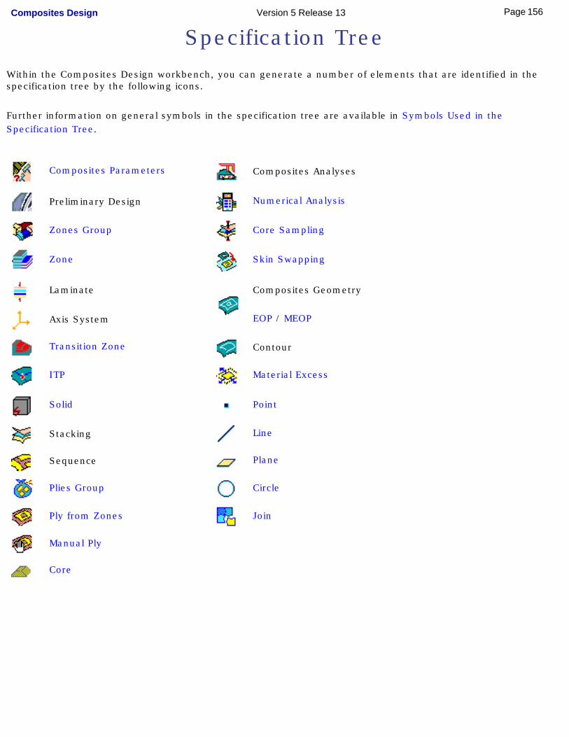
Specification TreeWithin the Composites Design workbench, you can generate a number of elements that are identified in the specification tree by the following icons.
Further information on general symbols in the specification tree are available in Symbols Used in the Specification Tree.
Composites Parameters Composites Analyses
Preliminary Design Numerical Analysis
Zones Group Core Sampling
Zone Skin Swapping
Laminate Composites Geometry
Axis System EOP / MEOP
Transition Zone Contour
ITP Material Excess
Solid Point
Stacking Line
Sequence Plane
Plies Group Circle
Ply from Zones Join
Manual Ply
Core
[ ]
156Page Composites Design Version 5 Release 13

Index
Aanalyzing
producibility
Bbisecting
lines bi-tangent and point
circles bi-tangent and radius
circles
CCircle
command
circles
command
Connection Generator
Core
core sample
EOP
Flattening
ITP
Laminate
Limit Contour
Manufacturing Data
157Page Composites Design Version 5 Release 13
Material Excess
Numerical Analysis
Plies From Zones
Plies Group
Ply
Ply Exploder
Ply export data
Producibility
Skin swapping
Solid From Zones
Stack-Up File From Plies
Stack-Up File From Zones
Transition Zone
Zone
Zones Group
connection generator
core
core sample creating
circles
circular arcs
core
Core Sample
exploded plies
ITP
limit contour
lines
manufacturing data
planes
plies from zones
plies manually
points
158Page Composites Design Version 5 Release 13
solid
stack-up file from plies
stack-up file from zones curves
joining
Ddefining
EEOP
EOP
Material Excess
MEOP
plies group
transition zone
zone
zones group
Eexporting
data
Fflattening
GGenerative Shape Design
interoperability geometry
159Page Composites Design Version 5 Release 13
joining
Iimporting
laminate
interoperability
ITP
JJoin
command
joining
Llaminate line
command
creating
lines
Mmanufacturing data
material excess
N
160Page Composites Design Version 5 Release 13
numerical analysis
Pplane
command
creating
plies group
ply
flattening
ply from zones point
command
creating point center and radius
circles
producibility
Sskin
swapping
solid from zones
stack-up file from plies
stack-up file from zones surfaces
joining
swapping
Tthree points
161Page Composites Design Version 5 Release 13
circles
transition zone tri-tangent
circles two points
circles two points and radius
circles
WWireframe
interoperability
Zzone
zones group
[
162Page Composites Design Version 5 Release 13