COMPOSITE CONSTRUCTION BONDING -...
6
AIRCRAFT BUILDING COMPOSITE CONSTRUCTION BONDING BY RON ALEXANDER During this series on composite con- struction, I am attempting to convey to potential builders the very basic knowl- edge necessary to construct a composite airplane. Composite building is not dif- ficult. It simply requires a fundamental knowledge of the basics. When you un- dertake the building of a composite aircraft, the plans or assembly manual will guide you through the process. The basic skills needed for this type of con- struction consist of 2 primary items: knowledge of how to do a basic layup and knowledge of how to bond pieces of material together. Building a com- posite airplane from a kit is similar to building a model airplane. You glue the pieces together. Now, obviously the glu- ing procedure for an aircraft is much more critical and sophisticated than with a model, but the basic principles are very similar. To review the material previously presented in the two preceding issues, I discussed the primary elements of a composite structure: core materials, re- inforcement materials, and resin sys- tems. Workshop space and tools needed were presented along with how to work with all of the basic materials. Various types of fillers were discussed and how to use them. The June article presented safety issues and outlined how to do a basic layup using fiberglass and resin. The proper inspection of a completed laminate was also given. We will now pick up at the next step of our layup — application of peel ply. PEEL PLY Peel ply is a polyester or nylon cloth material applied to the completed lam- inate while the resin is still wet. This cloth will not adhere to the layup thus allowing it to be peeled off at a later time, hence the words "peel ply". The application of peel ply is suggested when you are going to complete an- other laminate at a later time. If you are immediately going to apply an- other layer of cloth this step is not necessary. Peel ply provides an added benefit of absorbing excess resin from the composite skins. Assuming you are going to apply another laminate later, or you are com- pleting the final laminate, you will want to place peel ply onto the com- pleted surface. Cut the peel ply to the proper size and lay it over the laminate while the resin is still wet. One layer of peel ply is all you will need. Use a squeegee and a brush to work the resin up through the peel ply. You may have to add a small amount of resin to get the peel ply to bond adequately to the laminate and to completely impregnate the peel ply and thus fill the weave. After ensuring the peel ply is saturated onto the layup, set the piece aside to cure. After the resin has cured you must then remove the peel ply. This is very important! Failure to remove peel ply will result in an unsafe bond of the next layer of reinforcement material. (Note that a number of kit manufactur- ers will ship pre-molded parts that still n Fillet n Figure 1 TRIMMED PARTS SINGLE Joccie EXTERIOR SURFACE REINFORCED OVERLAPPING JOINTS MICRO / * 2 PLY BuiLD-ur LAYBR INTERIOR SURFA< F / "" l E*i i HLLIDER L*YLr / STRUCTURAL ADHESIVE _. / CORE 100 JULY 1999
Transcript of COMPOSITE CONSTRUCTION BONDING -...
AIRCRAFT BUILDING
COMPOSITE CONSTRUCTIONBONDING
BY RON ALEXANDER
During this series on composite con-struction, I am attempting to convey topotential builders the very basic knowl-edge necessary to construct a compositeairplane. Composite building is not dif-ficult. It simply requires a fundamentalknowledge of the basics. When you un-dertake the bui lding of a compositeaircraft, the plans or assembly manualwill guide you through the process. Thebasic skills needed for this type of con-struction consist of 2 primary items:knowledge of how to do a basic layupand knowledge of how to bond piecesof material together. Building a com-posite airplane from a kit is similar tobuilding a model airplane. You glue thepieces together. Now, obviously the glu-ing procedure for an aircraft is muchmore critical and sophisticated thanwith a model, but the basic principlesare very similar.
To review the material previouslypresented in the two preceding issues, Idiscussed the primary elements of acomposite structure: core materials, re-
inforcement materials, and resin sys-tems. Workshop space and tools neededwere presented along with how to workwith all of the basic materials. Varioustypes of fillers were discussed and howto use them. The June article presentedsafety issues and outlined how to do abasic layup using fiberglass and resin.The proper inspection of a completedlaminate was also given. We will nowpick up at the next step of our layup —application of peel ply.
PEEL PLY
Peel ply is a polyester or nylon clothmaterial applied to the completed lam-inate while the resin is still wet. Thiscloth will not adhere to the layup thusallowing it to be peeled off at a latertime, hence the words "peel ply". Theapplication of peel ply is suggestedwhen you are going to complete an-other laminate at a later time. If youare immediately going to apply an-other layer of cloth this step is not
necessary. Peel ply provides an addedbenefit of absorbing excess resin fromthe composite skins.
Assuming you are going to applyanother laminate later, or you are com-pleting the final laminate, you wil lwant to place peel ply onto the com-pleted surface. Cut the peel ply to theproper size and lay it over the laminatewhile the resin is still wet. One layer ofpeel ply is all you wil l need. Use asqueegee and a brush to work the resinup through the peel ply. You may haveto add a small amount of resin to getthe peel ply to bond adequately to thelaminate and to completely impregnatethe peel ply and thus fi l l the weave.After ensuring the peel ply is saturatedonto the layup, set the piece aside tocure. After the resin has cured youmust then remove the peel ply. This isvery important! Failure to remove peelply will result in an unsafe bond of thenext layer of reinforcement material.(Note that a number of kit manufactur-ers will ship pre-molded parts that still
n
Fillet
n
Figure 1
TRIMMED PARTS
SINGLE Joccie
EXTERIOR SURFACE
REINFORCED OVERLAPPING JOINTSMICRO
/*
2 PLY BuiLD-ur LAYBR
INTERIOR SURFA< F / "" l E*i i HLLIDER L*YLr/
STRUCTURAL ADHESIVE _.
/CORE
100 JULY 1999
have peel ply attached. It is imperativethis be removed prior to bonding thepieces together.)
After removal of the peel ply youwill see that the laminate is very smoothand requires little preparation for thenext layer of cloth or for the finishingprocess. The resulting surface is actu-ally fractured somewhat leaving it betterprepared for addi t ional bonding orpainting. Small glossy areas will bepresent on the peel-plied surface requir-ing abrading with 180 grit sandpaper orScotchbrite™ pads. Without using peelply, the composite surface will requireextensive sanding or filling to prepare itfor bonding or painting.
BONDING
Definition
Bonding is not a new process in air-craft building. In fact, bonding has beenused in aircraft construction since thevery beginning. The technique of glu-ing wood structures together has beenused for years. Many of the same glu-ing e l emen t s found in wood is alsofound in composites. The term bond-ing, as applied to composites, is used todescribe a common method for joiningcomposite structures. Bonding is theprocess in which previously manufac-tured component parts are attachedtogether during assembly of the air-plane. Bonding composites can also becompared to welding metal. It is de-signed to be a permanent jo in ingmethod. Several important points mustbe considered in bonding . We mustknow how much strength is needed inthe joint, the bonding area required,what type of material must be used toprovide the adhesion, and the procedureused to apply the bonding material.Preparing the surfaces that are to bebonded together is also crucial . Asstated earlier, the majority of compositekit aircraft require some type of bond-ing procedure.
The first method of bonding used inamateur-built aircraft involves a four-step process. The first step is to cutand trim the component parts to getthe proper shape and fit. The secondstep is to position the two pieces to-gether. This can be accomplished byusing temporary jigs or by temporarilygluing them together with a non-struc-tural adhesive. Third, we must fill anygaps tha t may exist as a resul t of
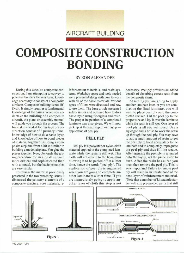
butting the two pieces together. The fi-nal step consists of actually creatingthe structural joint using wet (resinladen) strips of reinforcement material(usually fiberglass) bonded over thearea connecting the two componentstogether (see Figure 1). If we are bond-ing together two pieces that areperpendicular to each other as in Fig-ure 1, then we must create a fillet.
The strength of a joint that is joinedby a f i l l e t is derived from the rein-forcement material and not the filletitself. The fillet is needed to preventthe reinforcement fibers from makinga direct 90-degree bend without anyradius. Composite materials must havea bending radius just like sheet metal.The number of strips of reinforcementmaterial laid down over the fillet de-termines the strength of the bond.
An example of the type of construc-tion explained is found in mating awing rib to the wing skin. Another ex-ample is placing a bulkhead into afuselage. Both of these arc commontypes of construction techniques usedwhen building a kit composite airplane.
The second method of compositebonding is termed "adhesive bonding."Adhesive bonding involves assemblingcomponent parts together using a struc-tural adhesive in place of resins andfiberglass. Structural adhesives rangefrom preformulated, two part mixturesthat are in paste form to structural lami-nating resins that are mixed with flockedcotton or milled fiber to provide thenecessary strength. The first method ofbonding discussed uses laminat ingresins and reinforcement material tocreate a bonding overlap. Adhesivebonding requires the bonding area to beformed into the part when it is molded.This is usually accomplished by lower-ing one side of a part and raising a sideof the second part. This allows the twopieces that will be bonded to slide overeach other providing a precise fit. Thejoint that is formed when the pieces arejoined in this manner is referred to as a"joggle" (see Figure 2). With this typeof overlap the builder is required to laydown the structural adhesive and applysome clamping pressure.
Some kit manufacturers prefer to
Single or twin engine aircraft,Insight oilers a GEM to met your requirements
For information, use SPORT AVIATION'S Reader Service Card
SPORT AVIATION 101

Figure 3
combine both bonding methods toachieve the greatest possible strength.The key to achieving strength in anyjoint is to properly prepare the surfacesthat will be joined. The laminating resinor structural adhesive must bond well tothe surfaces. The surfaces must becleaned properly and sanded.
You will often hear the term "sec-ondary bonding" used in compositeconstruction. This type of bonding sim-ply refers to the bonding together ofpreviously cured composite parts usingthe methods outlined above. Secondarybonding is commonly found in mostcomposite kit aircraft. It requires propersurface preparation. Prepare the sur-faces according to the instructionsprovided by the kit manufacturer. Usu-ally, the surface will be abraded using180-grit sandpaper or a Scotchbritepad. Each of these wil l provide theproper surface preparation without cut-ting or damaging underlying fibers.
Steps of Bonding
When you receive your kit it wi l lusually consist of many pre-moldedparts that need to be bonded together.Sounds relatively simple — and it is— provided you carefully follow in-structions. You must first of all removeany peel ply, prepare the surfaces, andthen the pieces must be properly jiggedto maintain an accurate alignment.Then the actual process begins. So,let's take the steps one at a time. Wewill use a simple "T" bond of 2 piecesof material to illustrate the steps.
Preparation
Most of the construction process ofa kit aircraft involves secondary bond-102 JULY 1999
ing. This means it is critical to prop-erly prepare the surface. With aplans-built airplane or a kit airplanewhere you have just completed build-ing a part, the piece is already preparedfor the bonding step.
Assuming you are working withpre-molded parts, you must abrade thesurface to ensure an adequate bond.Failure to do so will result in an unsafebond. We have discussed this processearlier. Prepare the piece according tothe instructions of the kit manufac-turer. They will usually have you usesandpaper or Scotchbrite™ pads toscratch up the surface. 3M™ Rol-locdisks also work very quickly to pre-pare glass surfaces for bonding. Youwill want to make sure you have theproper fit between the pieces. A cer-tain amount of sanding may benecessary to ensure this fit. You do notwant any gaps between the pieces thatare to be bonded together. The piecesmust then be thoroughly cleaned to re-move any contaminants. Often residuefrom a mold release compound will bepresent on the piece. This must be re-moved. Acetone is often recommendedfor the initial cleaning followed imme-diately by a dry rag. The part shouldthen be cleaned with soap and water toremove any solvents and then dried.Again, follow the directions of the kitmanufacturer. I wil l amplify on thecleaning process in the next article.
Tack the Parts Together
The next step in the bondingprocess is to mate the pieces togetherand glue them in place using a non-structural glue (Figure 3). This simplyallows you to begin the bondingprocess. You can use 5-minute epoxy,
hot glue or instant glue to hold thepieces together. The parts only need tobe tacked in just enough areas to holdthem in place. This is not the f inalbonding of the pieces — it is simply amethod of holding them together whilewe actually complete the bonding op-eration. None of the glues mentionedshould be considered as structurallysound. Hold the pieces together untilthe glue sets up. Figure 2 shows ourtwo pieces glued together using 5-minute epoxy. Assembly instructionswill often require the use of clecos,screws, or clamps to attach the piecestogether for the bonding process.
Note: As a reminder, remember to re-move any peel ply that may be present onthe component parts prior to bonding.
Create a Fillet
Once the temporary bond has hard-ened, a fillet needs to be made. Thisf i l le t provides a radius for the rein-forcement material that will be bondedon next. The fillet alone is not strongenough to bond the parts together. Drymicro or SuperFil is used to make anon-structural fillet. Structural fillets,if required, are made by substitutingmicroballoons with cotton flox.
Creating a fillet is relatively simple.Mix the SuperFil or micro and place itin a sandwich bag or in the middle of apiece of plastic. Close it up and snip asmall hole in the bottom of the bag(see Figure 4). This is similar to acake-icing dispenser. Now squeeze themixture from the bag along the cornerarea where the pieces are joined. Asmall amount is sufficient. An optimalfi l let will have about a 3/16-inch to5/16-inch radius.
Figure 4After placing the SuperFil along the
fillet area, take a tongue depressor andsmooth the mixture into the cornerarea. Rounding the end of a tongue de-pressor with a pair of scissors will
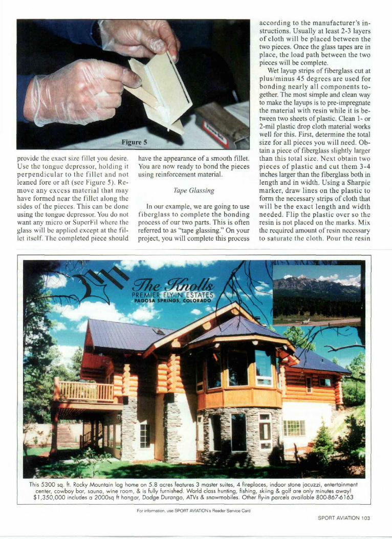
provide the exact size fillet you desire.Use the tongue depressor, holding itperpendicular to the f i l l e t and notleaned fore or aft (see Figure 5). Re-move any excess mater ia l tha t mayhave formed near the fillet along thesides of the pieces. This can be doneusing the tongue depressor. You do notwant any micro or SuperFil where theglass wil l be applied except at the fil-let itself. The completed piece should
have the appearance of a smooth fillet.You are now ready to bond the piecesusing reinforcement material.
Tape Glassing
In our example, we are going to usefiberglass to complete the bondingprocess of our two parts. This is oftenreferred to as "tape glassing." On yourproject, you will complete this process
according to the manufacturer's in-structions. Usually at least 2-3 layersof cloth wi l l be placed between thetwo pieces. Once the glass tapes are inplace, the load path between the twopieces will be complete.
Wet layup strips of fiberglass cut atplus/minus 45 degrees are used forbonding nearly all components to-gether. The most simple and clean wayto make the layups is to pre-impregnatethe material with resin while it is be-tween two sheets of plastic. Clean 1- or2-mil plastic drop cloth material workswell for this. First, determine the totalsize for all pieces you will need. Ob-tain a piece of fiberglass slightly largerthan this total size. Next obtain twopieces of plastic and cut them 3-4inches larger than the fiberglass both inlength and in width. Using a Sharpiemarker, draw lines on the plastic toform the necessary strips of cloth thatwill be the exact length and widthneeded. Flip the plastic over so theresin is not placed on the marks. Mixthe required amount of resin necessaryto saturate the cloth. Pour the resin
PREMIER FLY-IN ESTATESPAOOSA SPRINGS, COLORAPO
This 5300 sq. ft. Rocky Mountain log home on 5.8 acres features 3 master suites, 4 fireplaces, indoor stone Jacuzzi, entertainmentcenter, cowboy bar, sauna, wine room, & is fully furnished. World class hunting, fishing, skiing & golf are only minutes away!
$1,350,000 includes a 2000sq ft hangar, Dodge Durango, ATVs & snowmobiles. Other fly-in parcels available 800-867-6163
For information, use SPORT AVIATION'S Reader Service Card
SPORT AVIATION 103

Smoothing resin into cloth between sheets of plastic.
over the plastic and place the fiberglasson top of the resin. Next place the sec-ond piece of plastic over the resin.
Using a squeegee, work the resin intothe fibers through the plastic. In otherwords, you will be placing the squeegeeon the plastic, not on the cloth. This en-ables you to keep everything clean andneat. Wet out the fibers completely justlike any other layup. You can now pickup the entire piece of material and han-dle it without getting resin everywhere.
The next step is to use standard scis-sors and cut out the tapes you will needalong the lines on the plastic (see Figure6). As you cut the strips, draw the scis-sors slightly toward you. This will enableyou to make neat, easy cuts.
Next, lightly moisten the area to belaminated (on our "T") with resin usinga brush. This will ensure that the bond isnot resin-starved. Remove the plasticfrom one side of the tape. Place the stripdown with the remaining piece of plasticfacing up. Use a squeegee over the topof the plastic to remove any air bubblesand to smooth the resin evenly. After the104 JULY 1999
tape is in place you can then remove thetop piece of plastic. The process is thenrepeated for additional layers of cloth.Be sure to remove the plastic. Plans usu-ally call for the pieces of reinforcementmaterial to be stepped out with succeed-ing layers. In other words, if the firstlayer is 2 inches wide the next layerwould be 3 inches wide. The widestpiece will be on the top.
Thoroughly inspect the piece for airbubbles and resin starved areas.
As you will see from the completedpiece (Figure 7), the tape is providingthe strength of the bond. This is a veryefficient and effective method of bond-ing two composite parts together. Again,it is a commonly used technique for in-stalling ribs in wings or bulkheads in afuselage. Use of the plastic is not neces-sary, but it does allow you to remainneat and clean.
The final step is to place peel ply overthe material. Laminate a strip of peel plyover the surface and allow the resin tocure. This will eliminate the sharp edgesthat will otherwise result from the fiber-glass material. Remember to remove thepeel ply after the resin has cured.
Joggles
Joggles are simply joints that havebeen pre-molded to fit precisely to-gether. They overlap each other and areusually bonded together using a struc-tural adhesive. This type of constructionis very common in the mating togetherof fuselage parts. After bonding theparts together at the joggle, reinforce-ment material is usually applied foradded strength.
Often you will be required to trim ex-cess material off a joggle prior tobonding. Usually you will place the twopieces together and then drill holes to al-low for the installation of clecos. (Thesame clecos used for sheet metal con-struction.) Some instructions call for theuse of clamps or even strips of woodglued on the surface to hold it in placeand to maintain proper alignment. Thisw i l l often be done in a jig to ensurealignment of the parts.
After the pieces are mated together,and the proper fit attained, you will thenmix the structural adhesive. Structuraladhesives are usually in a thick pasteform. They consist of a Part A and a Part
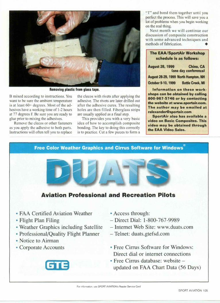
Removing plastic from glass tape.B mixed according to instructions. Youwant to be sure the ambient temperatureis at least 60+ degrees. Most of the ad-hesives have a working time of 1-2 hoursat 77 degrees F. Be sure you are ready toglue prior to mixing the adhesives.
Remove the clecos or other fastenersas you apply the adhesive to both parts.Instructions will often tell you to replace
the clecos with rivets after applying theadhesive. The rivets are later drilled outafter the adhesive cures. The resultingholes are then filled. Fiberglass stripsare usually applied as a final step.
This provides you with a very basicidea of how to accomplish compositebonding. The key to doing this correctlyis to practice. Cut a few pieces to form a
"T" and bond them together unti l youperfect the process. This will save you alot of problems when you begin workingon the real thing.
Next month we wi l l continue ourdiscussion of composite constructionwith some advanced techniques andmethods of fabrication. ^
The EAA/SportAir Workshopschedule is as follows:
August 28,1999 Chino, CA(one day conference)
August 28-29,1999 North Hampton, NHOctober 9-10,1999 Battle Creek, Ml
Information on these work-shops can be obtained by calling800-967-5746 or by contactingthe website at www.sportair.com.The author may be emailed [email protected]
SportAir also has available avideo on Basic Composites. Thisvideo may be obtained throughthe EAA Video Sales.
Free Color Weather Graphics and Cirrus Software for Windows
Aviation Professional and Recreation Pilots
FAA Certified Aviation WeatherFlight Plan FilingWeather Graphics including SatelliteProfessional/Quality Flight PlannerNotice to AirmanCorporate Accounts
• Access through:-Direct Dial: 1-800-767-9989- Internet Web Site: www.duats.com- Telnet: duats.gtefsd.com
• Free Cirrus Software for Windows:Direct dial or internet connections
• Free Cirrus database: website -updated on FAA Chart Data (56 Days)
For information, use SPORT AVIATION s Reader Service Card
SPORT AVIATION 105