components - K.R. West
10
www.enerpacwh.com 187 ® 188 191 192 193 190 189 194-196 Pressure switches Digital pressure gauges Gauge accessories Manifolds, couplers, hoses, tubing High pressure filters, hydraulic oil IC, PB PSCK DG GA, GS NV, FM A, AH/R HLS, H, T FL, HF Pressure gauges G High pressure fittings BFZ, FZ components t series t page
Transcript of components - K.R. West

www.enerpacwh.com 187®
188
191
192
193
190
189
194-196
Pressure switches
Digital pressure gauges
Gauge accessories
Manifolds, couplers, hoses, tubing
High pressure filters, hydraulic oil
IC, PB PSCK
DG
GA, GSNV, FM
A, AH/R HLS, H, T
FL, HF
Pressure gauges G
High pressure fittings BFZ, FZ
componentst series t page

188 ®
190 ▸
PS
CK
2
9903
4
194 ▸
PB-4
Col
let-
Lok®
pr
oduc
t lin
eS
win
g cl
amps
Line
ar c
lam
psPo
wer
sou
rces
Valv
esP
alle
t com
pone
nts
Wor
k su
ppor
tsS
yste
m
com
pone
nts
Shown: PSCK-8, IC-51
Pressure switches IC, PSCK-series
Reliable electrical control of hydraulic power
• Compact design minimizes space requirements on fixture
• Switch is easily adjustable to meet system requirements
Enerpac remote mounted
pressure switches monitor the
hydraulic system to determine
any change of pressure. The
signal can then be used to
control the pump, or other
peripheral devices.
IC-seriesThe IC-series electrical pressure switches provide pressure readings for monitoring and/or control of hydraulic system pressure in workholding systems.
z Integrated in your hydraulic system, the pressure switch can be used to automate your clamping cycles.
Pressure: 500-7500 psi
Accuracy: 2%
Fittings
Gauges
E Presostatos
F Pressostats
D Druckschalter
Hydraulic connection
Product selection
Do not exceed the maximum pressure.
Important
mounting dimensions
Adjustable Electrical Model Deadband Switch Oil pressure specifications number point port range repeatability psi at 50/60 Hz psi % of range lb
t Electrical pressure switches
500-3500 125 VAC @ 5 A IC-30 100 - 500 + /-2 SAE #4 1.0
500-3500 125 VAC @ 5 A IC-31 100 - 500 + /-2 .250-18 NPT 1.0
3000-7500 125 VAC @ 5 A IC-50 250 - 800 + /-2 SAE #4 1.0
3000-7500 125 VAC @ 5 A IC-51 250 - 800 + /-2 .250-18 NPT 1.0
1450-5000 115 VAC @ 2 A PSCK-8 250 - 800 + /-2 Manifold mount 0.8
290-3045 115 VAC @ 2 A PSCK-9 250 - 800 + /-2 Manifold mount 0.8
– – PB-4 – – G ¼" .25
IC series
PSCK-8, 9
Options
G1/4" Male
www.enerpacwh.com 189®
190 ▸
DG
R-1
B
194 ▸
191 ▸
Yellow pages
System
com
ponents
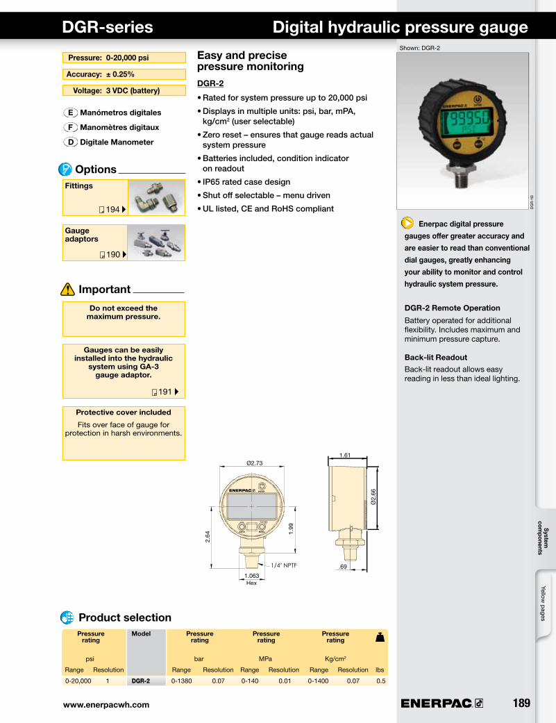
Pressure: 0-20,000 psi
Accuracy: ± 0.25%
Gauge adaptors
Fittings
Options
E Manómetros digitales
F Manomètres digitaux
D Digitale Manometer
Voltage: 3 VDC (battery)
DGR-series Digital hydraulic pressure gaugeShown: DGR-2
Enerpac digital pressure
gauges offer greater accuracy and
are easier to read than conventional
dial gauges, greatly enhancing
your ability to monitor and control
hydraulic system pressure.
DGR-2 Remote Operation
Battery operated for additional flexibility. Includes maximum and minimum pressure capture.
Back-lit ReadoutBack-lit readout allows easy reading in less than ideal lighting.
Easy and precise pressure monitoringDGR-2
•Ratedforsystempressureupto20,000psi
•Displaysinmultipleunits:psi,bar,mPA,kg/cm2(userselectable)
•Zeroreset–ensuresthatgaugereadsactualsystempressure
•Batteriesincluded,conditionindicatoronreadout
•IP65ratedcasedesign
•Shutoffselectable–menudriven
•ULlisted,CEandRoHScompliant
Pressure Model Pressure Pressure Pressure rating rating rating rating
psi bar MPa Kg/cm2
Range Resolution Range Resolution Range Resolution Range Resolution lbs
Product selection
Important
Do not exceed the maximum pressure.
Gauges can be easily installed into the hydraulic
system using GA-3 gauge adaptor.
Protective cover included
Fits over face of gauge for protection in harsh environments.
0-20,000 1 DGR-2 0-1380 0.07 0-140 0.01 0-1400 0.07 0.5

190 ®
99-0
79
99-0
57
Col
let-
Lok®
pr
oduc
t lin
eS
win
g cl
amps
Line
ar c
lam
psPo
wer
sou
rces
Valv
esP
alle
t com
pone
nts
Wor
k su
ppor
tsS
yste
m
com
pone
nts
Enerpac gauges provide a safe and inexpensive monitoring system for your hydraulic circuitHighly reliable and accurate pressure sensing
• ± 1.5% accuracy of full scale
• All pressure sensing parts sealed and dampened by glycerine for long life
• Includes safety blow-out disk and pressure equalizing membrane to prevent overpressurization
• Copper alloy, coiled safety Bourdon tube for 1000 psi and higher
• Dual psi and bar scale readings, 2.5 inch gauge face
Shown: GS-2, G-2512L, GS-3
Pressure gauges and accessories Application & selection
Gauge accessories for easy installation
• Needle valves providing positive shut-off
• 303 stainless steel stem (NV-251)
• Snubber valves to control pressure surges between gauge and hydraulic system
• Gauge adaptors – male end screws into pump or cylinder, female port accepts hose or coupler, the third port is for gauge connection
• FM-25NG for panel mounting of 2.50 inch diameter gauges
Product selection
t Pressure gauge – Lower mount
t Pressure gauge – Rear mount
Pressure gauge Pressure Model PSI Bar A B D G mounting style range number graduation graduation
Major Minor Major Minor psi bar psi psi bar bar in in in
0-100 0-7 G-2509L 10 2 1 0,01 3.31 1.46 2.50 1/4" NPT
0-160 0-11 G-2510L 10 2 1 0,02 3.31 1.46 2.50 1/4" NPT
0-200 0-14 G-2511L 50 5 1 0,02 3.31 1.46 2.50 1/4" NPT
0-300 0-20 G-2512L 50 5 5 0,05 3.31 1.46 2.50 1/4" NPT
0-600 0-40 G-2513L 100 10 10 1 3.31 1.46 2.50 1/4" NPT
0-1000 0-70 G-2514L 100 20 10 1 3.31 1.46 2.50 1/4" NPT
0-2000 0-140 G-2515L 500 50 10 2 3.31 1.46 2.50 1/4" NPT
0-3000 0-200 G-2516L 500 50 50 5 3.31 1.46 2.50 1/4" NPT
0-6000 0-400 G-2517L 1000 100 100 10 3.31 1.46 2.50 1/4" NPT
0-10,000 0-700 G-2535L 2000 200 100 10 3.31 1.46 2.50 1/4" NPT
0-1000 0-70 G-2514SL 100 20 10 1 3.66 1.23 2.50 SAE#4
0-3000 0-200 G-2516SL 500 50 50 5 3.66 1.23 2.50 SAE#4
0-6000 0-400 G-2517SL 1000 100 100 10 3.66 1.23 2.50 SAE#4
0-10,000 0-700 G-2535SL 2000 200 100 10 3.66 1.23 2.50 SAE#4
0-1000 0-70 G-2531R 100 20 10 1 2.48 1.46 2.50 1/4" NPT
0-6000 0-400 G-2534R 1000 100 100 10 2.48 1.46 2.50 1/4" NPT
0-10,000 0-700 G-2537R 2000 200 100 10 2.48 1.46 2.50 1/4" NPT
0-1000 0-70 G-2531SR 100 20 10 1 2.46 1.23 2.50 SAE #4
0-3000 0-200 G-2533SR 500 50 50 5 2.46 1.23 2.50 SAE #4
0-6000 0-400 G-2534SR 1000 100 100 10 2.46 1.23 2.50 SAE #4
0-10,000 0-700 G-2537SR 2000 200 100 10 2.46 1.23 2.50 SAE #4
0-1000 0-70 1531R 100 20 10 1 1.99 0.98 1.50 1/8" NPT
0-3000 0-200 1533R 500 100 50 10 1.99 0.98 1.50 1/8" NPT
0-6000 0-400 1534R 1000 100 100 10 1.99 0.98 1.50 1/8" NPT
0-10,000 0-700 1537R 2000 200 100 10 1.99 0.98 1.50 1/8" NPT

www.enerpacwh.com 191®
192 ▸
189 ▸
188 ▸
157 ▸
202 ▸
GA-1 GA-2, -3, -4
GS-2, -3GA-918
NV-251, V-91 FM-25NG
Yellow pages
System
com
ponents
Hoses and couplers
Digital gauges
Pressure switches
Important
Do not exceed maximum pressure.
Gauge snubbers or needle valves are recommended for
high cycle applications.
V-10 Auto Damper® valve
Pressure: 0-10,000 psi
Accuracy: 1.5% /full scale
Gauge face: ø 2.5 inch
E Manómetros
F Manomètres
D Manometer
Product dimensions in inches [ ]
Dimensions & options G, GA, GS, NV, FM, V-series
Do not keep gauges under permanent pressure. The use of shut-off valves
is recommended.
For basic system set-up information, refer to our “Yellow Pages” section.
Gauge Max. Model Dimensions port pressure number NPT psi A B C D E F S S1
t Gauge adaptors
t Swivel gauge adaptor
t Gauge shut-off valves
t Gauge snubber valves
t Flange mounting for panel mounting of G series gauges
Options
1/2" 10,000 GA-1 2.81 1.24 1/2"NPT 3/8"NPT 3/8"NPT 1.25 – –
1/2" 10,000 GA-2 6.10 1.38 1/2"NPT 3/8"NPT 3/8"NPT 1.25 – –
1/4" 10,000 GA-3 5.25 1.38 1/4"NPT 3/8"NPT 3/8"NPT 1.25 – –
1/2" 10,000 GA-4 4.38 1.38 1/2"NPT 1/4"NPT 3/8"NPT 1.25 – –
1/2" 10,000 GA-918 2.25 1.72 1/2"NPT 1/2"NPT 1.30 – 1.13 1.50
1/4" 10,000 NV-251 2.25 1.14 1/4"NPT 1/4"NPT .17 .75 2.25 2.50
1/2" 10,000 V-91 3.50 1.25 1/2"NPT 1/2"NPT .19 1.25 2.50 2.50
1/4" 5000 GS-2 1.63 .018 1/4"NPT SAE #4 – – .75 –
1/4" 5000 GS-3 1.63 .018 1/4"NPT G1/4" – – .75 –
– – FM-25NG 2.95 .17 2.51 .07 3.35 .14 – –

192 ®
99-1
05
194 ▸
AH-650
AH-652
AH-654
AR-650
Col
let-
Lok®
pr
oduc
t lin
eS
win
g cl
amps
Line
ar c
lam
psPo
wer
sou
rces
Valv
esP
alle
t com
pone
nts
Wor
k su
ppor
tsS
yste
m
com
pone
nts
Important Manifolds
• Easy to connect
• Mounting holes on all models
Couplers
• Spee-D-Coupler® design allows cylinder to be connected and disconnected in seconds
• For more safety: couplers cannot be connected or disconnected while under hydraulic pressure
Hydraulic hoses and tubings
• Heavy-duty coating for abrasion resistance
• Resistant against mineral based hydraulic oil as well as water glycols
• High pressure steel tubing for permanent installations
Use genuine Enerpac
manifolds, couplers, hoses
and tubings to connect your
workholding cylinders or
fixtures to the hydraulic
power source.
A series, Manifolds
For multiple hydraulic line connections at one central location directing oil to or from a pressure source.
AH/AR series, Couplers
Quick disconnect low leakage couplers for easy connection of hydraulic circuits. HLS series, Hoses
High pressure hydraulic hoses, featuring a heavy-duty protective plastic coating.
T-series, Tubing
High pressure steel tubing, available in 5 ft. lengths.
Shown: HLS, HF, AH, AR, FL, T, A-series
Options Fittings
Manifolds, couplers, hoses, tubing
A-60, -61, -64, -65
Do not exceed the maximum pressure.
Inspect hoses and tubing frequently and replace
as required.
A-63
A-66
Manifolds dimensions in inches [ ]
Male coupler half.250-18 NPT
Male coupler halfG1/4” BSPP
Male coupler halfSAE #4 .437-20 UNF
Female coupler half.250-18 NPT
Hoses CouplersLength Model Internal Maximum number diameter pressure ft in psi
t 1/4", 37° flare
1 HLS-512 .19 5000
2 HLS-524 .19 5000
3 HLS-536 .19 5000
4 HLS-548 .19 5000
5 HLS-560 .19 5000
10 HLS-5120 .19 5000
t3/8" NPT
3 H-9203 .25 10,000
6 H-9206 .25 10,000
10 H-9210 .25 10,000
Tubing
5 T-2560 .152 .25 5000
Number Model A B C D D1 D2 E F F1 F2 of ports number lbs
Length Model Internal External Max. number diameter diameter pressure ft in in psi
2 x 4 A-63 3.00 3.00 2.00 .25 – – SAE #4 – – – 2.0
5 A-60 3.50 1.25 1.25 .28 1.50 1.00 SAE #4 1.50 1.00 1.75 1.0
7 A-61 6.50 1.25 1.25 .28 1.50 1.25 SAE #4 1.00 1.25 3.25 1.4
7 A-64 7.00 1.25 1.25 .25 3.00 1.25 .375-18 NPT 1.50 1.25 3.50 3.3
7 A-65 14.5 1.25 1.25 .25 8.00 1.25 .375-18 NPT 4.00 1.25 7.25 6.1
6 A-66 2.30 1.63 2.00 .52 1.50 – .375-18 NPT – – – 1.8

www.enerpacwh.com 193®
194 ▸
99-0
47
Yellow pages
System
com
ponents
High-pressure filters
• Keep your hydraulic system clean
• Pleated stainless steel wire mesh screen construction provides large filter area in a compact size
• Rated for full system pressure up to 5000 psi
• Bi-directional design allows filtration of oil in either flow direction
• Two piece body construction for easy replacement of filter elements
• High flow rates are obtainable with a minimum pressure drop
• Threaded port connections on each end simplify installation
Hydraulic oil
• Ensures effective lubricity
• Protects essential parts
FL series
Hydraulic oil
Fittings
Do not exceed the maximum pressure.
Important
Options
Note: Viscosity index: 100 min
z Hydraulic power is distributed by manifolds and transported by hoses and tubing.
Filtration
E Mangueras, Filtros Acoplamientos, Aceite
F Flexibles, Filtres Raccords, Huile
D Schläuche, Filter Kupplungen, Öl
High-pressure filters
Compact in line high pressure filters prevent chips and debris that have entered the hydraulic fluid system from damaging hydraulic system components.
Hydraulic oil
Use only genuine Enerpac hydraulic oil to guarantee optimal performance and long life of your hydraulic equipment.
20 micron filter provides the longest service life before element replacement
10 micron filter recommended for more sensitive hydraulic components
High in line pressure filtersModel Filtration Filter element setnumber micron
Nominal Absolute lbs
0 °F <12,000 S.U.S100 °F 150/165 S.U.S210 °F 42/45 S.U.SFlash, C.O.C. 400°FPour point -25°FAniline point 210/220 °F
Contents Model Specifications number genuine Enerpac hydraulic oil
Gal
.25 HF-100
1 HF-101
5 HF-102
55 HF-104
High-pressure filters, hydraulic oil
0
Oil flow (gal/min) u
Pressure drop vs oil flow
Pres
sure
dro
p (p
si) u
0
400
300
200
100
4321
FL-2101 (10 micron)FL-2201 (20 micron)
FL-2101 10 25 FL-2101K .4
FL-2201 20 40 FL-2201K .4

194 ®
99-1
19
99-0
36
Col
let-
Lok®
pr
oduc
t lin
eS
win
g cl
amps
Line
ar c
lam
psPo
wer
sou
rces
Valv
esP
alle
t com
pone
nts
Wor
k su
ppor
tsS
yste
m
com
pone
nts
High Pressure Fittings Selection & dimensions Shown: FZ-2052, FZ-2054, FZ-2023
Fitting are used to connect
all cylinders, components,
power sources, tubes, gauges
and hoses in a hydraulic
system. Enerpac fittings
provide flexible, safe and leak-
free connections.
z Multiple hydraulic line connections are easily installed with Enerpac fittings and manifolds.
Proper connection for hydraulic components
• Male and female NPT, SAE, BSPP threaded fittings in common sizes allow easy connection of all components.
• BFZ and FZ-1000 models are 10,000 psi maximum pressure
• FZ-2000 models are 5000 psi maximum pressure
t Adapters
Female Male
1/4" NPT 1/8" NPT 10,000 FZ-1642 1.21 3/4" 1/8"-27 NPT 1/4"-18 NPT
3/8" NPT 1/4" NPT 10,000 FZ-1055 1.44 7/8" 1/4"-18 NPT 3/8"-18 NPT
1/2" NPT 1/4" NPT 10,000 FZ-1633 1.69 1-1/8" 1/4"-18 NPT 1/2"-14 NPT
1/2" NPT 3/8" NPT 10,000 FZ-1634 1.69 1-1/8" 3/8"-18 NPT 1/2"-14 NPT
t Reducers
Female Male
1/4" NPT 3/8" NPT 10,000 FZ-1630 .86 3/4" 3/8"-18 NPT 1/4"-18 NPT
1/4" NPT 1/2" NPT 10,000 FZ-1661 1.11 7/8" 1/2"-14 NPT 1/4"-18 NPT
SAE #6 SAE #8 5000 FZ-2029 1.38 1-1/16" 9/16"-18 3/4"-16
t NPT Male Nipples
1/4" NPT 1/4" NPT 10,000 FZ-1608 1.45 5/8" 1/4"-18 NPT 1/4"-18 NPT
3/8" NPT 3/8" NPT 10,000 FZ-1617 1.45 3/4" 3/8"-18 NPT 3/8"-18 NPT
3/8" NPT 3/8" NPT 10,000 FZ-1619 2.00 3/4" 3/8"-18 NPT 3/8"-18 NPT
3/8" NPT G1/4" 10,000 BFZ-305 1.42 3/4" 3/8"-18 NPT G1/4"-19
t NPT Female Connectors
1/4" NPT 1/4" NPT 10,000 FZ-1605 1.13 3/4" 1/4"-18 NPT 1/4"-18 NPT
3/8 NPT 1/4" NPT 10,000 FZ-1615 1.13 7/8" 3/8"-18 NPT 1/4"-18 NPT
3/8" NPT 3/8" NPT 10,000 FZ-1614 1.13 7/8" 3/8"-18 NPT 3/8"-18 NPT
1/2" NPT 3/8" NPT 10,000 FZ-1625 1.50 1-1/8" 1/2"-14 NPT 3/8"-18 NPT
t NPT Elbows
1/4" NPT 1/4" NPT 10,000 FZ-1638 .88 3/4" 1/4"-18 NPT 1/4"-18 NPT
3/8" NPT 3/8" NPT 10,000 FZ-1610 1.02 7/8" 3/8"-18 NPT 3/8"-18 NPT
t NPT Tee
1/4" NPT 1/4" NPT 10,000 FZ-1637 1.76 3/4" 1/4"-18 NPT 1/4"-18 NPT
3/8" NPT 3/8" NPT 10,000 FZ-1612 2.04 7/8" 3/8"-18 NPT 3/8"-18 NPT
t NPT Cross
3/8" NPT 3/8" NPT 10,000 FZ-1613 2.04 7/8" 3/8"-18 NPT 3/8"-18 NPT
From To Max. Model Dimensions in inches pressure number
A B C D psi
Product selection

www.enerpacwh.com 195®
190 ▸
192 ▸
A
D
C
B
Yellow pages
System
com
ponents
Selection, dimensions & options BFZ, FZ-series
Gauges
Do not exceed the maximum pressure.
Important
Options
z High presure hydraulic fittings allow connection of many components with minimum effort.
Pressure: 0-10,000 psi
Threads: NPT, SAE, BSPP
For tubing: .25 in/.375 in/8mm
E Acoplamientos
F Raccords
D Verschraubungen
Manifolds,couplers,hoses, tubing
Use fittings and tubing in high cycle applications andareas having excessive heat
or weld splatter.
To seal NPT threads useanaerobic thread sealers
or Teflon paste.Apply Teflon tape one thread
from the end of the fitting, to prevent itfrom winding up in the
hydraulic system.
From To Max. Model Dimensions in inches pressure number
psi A B C D
Product selection
t Adapters
Male Female
1/8" NPT SAE #4 5000 FZ-2075 1.21 11/16" 1/8"-27 NPT 1/4"-18 NPT
1/4" NPT SAE #4 5000 FZ-2042 1.31 11/16" 1/4"-18 NPT 7/16"-20
1/4" NPT G1/4" 10,000 BFZ-16411 1.38 3/4" 1/4"-18 NPT G1/4"
SAE #4 1/8" NPT 5000 FZ-2008 1.00 9/16" 7/16"-20 1/8"-27 NPT
SAE #4 1/4" NPT 5000 FZ-2007 1.16 3/4" 7/16"-20 1/4"-18 NPT
SAE #2 SAE #4 5000 FZ-2022 1.03 11/16" 5/16"-24 7/16"-20
SAE #6 1/4" NPT 5000 FZ-2056 1.16 3/4" 9/16"-18 1/4"-18 NPT
SAE #8 1/4" NPT 5000 FZ-2067 1.13 7/8" 3/4"-16 1/4"-18 NPT
SAE #8 3/8" NPT 5000 FZ-2069 1.28 7/8" 3/4"-16 3/8"-18 NPT
G 1/8" 1/8" NPT 5000 FZ-2055 .97 5/8" G 1/8"-28 1/8"-27 NPT
G 1/8" 1/4" NPT 5000 FZ-2060 1.28 3/4" G 1/8"-28 1/4"-18 NPT
G 1/8" #4 SAE 5000 FZ-2066 1.00 11/16" G 1/8"-28 7/16"-20
G 1/4" 1/4" NPT 5000 FZ-2023 1.28 3/4" G 1/4"-19 1/4"-18 NPT
G 1/4" #4 SAE 5000 FZ-2065 1.11 3/4" G 1/4"-19 7/16"-20
t Straight union
SAE #4 SAE #4 5000 FZ-2005 1.27 9/16" 7/16"-20 7/16"-20
SAE #6 SAE #6 5000 FZ-2028 1.41 11/16" 9/16"-18 9/16"-18
SAE #8 SAE #8 5000 FZ-2040 1.56 7/8" 3/4"-16 3/4"-16
tStraight union to tube ends
ø.25 ø.25 5000 FZ-2033* 1.38 1/2" 7/16"-20 ø.25
ø.25 ø.25 5000 FZ-2013** 2.03 1/2" 7/16"-20 ø.25
tAdaptors to tube end
Male Tube size
1/8" NPT ø.25 5000 R-1054* 1.22 1/2" 1/8"-27 NPT ø.25
1/4" NPT ø.25 5000 FZ-2020* 1.42 9/16" 1/4"-18 NPT ø.25
1/4" NPT ø.375 5000 FZ-2072* 1.43 5/8" 1/4"-18 NPT ø.375
1/4" NPT ø.25 5000 FZ-2012** 1.32 9/16" 1/4"-18 NPT ø.25
3/8" NPT ø.25 5000 FZ-2061* 1.44 3/4" 3/8"-18 NPT ø.25
3/8" NPT ø.375 5000 FZ-2068* 1.44 3/4" 3/8"-18 NPT ø.375
SAE #2 ø.25 5000 FZ-2025* 1.02 9/16" 5/16"-24 ø.25
SAE #4 ø.25 5000 FZ-2019* 1.23 9/16" 7/16"-20 ø.25
SAE #4 ø.25 5000 FZ-2001** 1.13 9/16" 7/16"-20 ø.25
SAE #6 ø.25 5000 FZ-2059* 1.28 11/16" 9/16"-18 ø.25
SAE #8 ø.25 5000 FZ-2039* 1.38 7/8" 3/4"-16 ø.25
SAE #8 ø.375 5000 FZ-2070* 1.38 7/8" 3/4"-16 ø.375
G1/8" ø.25 5000 FZ-2053* 1.18 14 mm G1/8"-28 ø.25
G1/4" ø.25 5000 FZ-2054* 1.37 19 mm G1/4"-19 ø.25
G1/4" ø.375 5000 FZ-2064* 1.38 19 mm G1/4"-19 ø.375
tElbow to tube end
Male Tube size
1/8" NPT ø.25 5000 FZ-2074* 0.78 7/16" 1/8"-27 NPT ø.25
1/4" NPT ø.25 5000 FZ-2073* 1.09 9/16" 1/4"-18 NPT ø.25
1/4" NPT ø.25 5000 FZ-2076** 1.09 9/16" 1/4"-18 NPT ø.25
1/4" NPT ø.375 5000 FZ-2081* 1.09 9/16" 1/4"-18 NPT ø.375
3/8" NPT ø.25 5000 FZ-2082* 1.22 3/4" 3/8"-18 NPT ø.25
3/8" NPT ø.375 5000 FZ-2083* 1.22 3/4" 3/8"-18 NPT ø.375
SAE #2 ø.25 5000 FZ-2024* 0.92 7/16" 5/16"-24 ø.25
SAE #4 ø.25 5000 FZ-2035* 1.03 9/16" 7/16"-20 ø.25
SAE #4 ø.25 5000 FZ-2002** 1.03 9/16" 7/16"-20 ø.25
SAE #8 ø.375 5000 FZ-2071* 1.45 7/8" 3/4"-16 ø.375
G1/8" ø.25 5000 FZ-2051* 1.03 14mm G1/8"-28 ø.25
G1/4" ø.25 5000 FZ-2052* 1.25 19mm G1/4"-19 ø.25
ø.25 ø.25 5000 FZ-2014** 0.89 9/16" ø.25 ø.25*Flared **Flareless

196 ®
99-0
60
192 ▸
Col
let-
Lok®
pr
oduc
t lin
eS
win
g cl
amps
Line
ar c
lam
psPo
wer
sou
rces
Valv
esP
alle
t com
pone
nts
Wor
k su
ppor
tsS
yste
m
com
pone
nts
From To Max. Model Dimensions in inches pressure number
psi A B C D
t Swivel banjo BSPP to tube
Male Tube size
G1/4" ø 8mm 10,000 BFZ-307** 1.14 19mm G1/4"-19 ø 8mm
t Swivel T-banjo BSPP to tube
Male Tube size
G 1/4" ø 8mm 10,000 BFZ-309** 1.14 19mm G 1/4"-19 ø 8mm
t Union tee
ø.25 ø.25 5000 FZ-2021* 1.78 9/16" 7/16"-20 ø.25
ø.25 ø.25 5000 FZ-2015** 1.78 9/16" 7/16"-20 ø.25
t Branch tee
Male Tube size
SAE #4 ø.25 5000 FZ-2036* 1.78 9/16" 7/16"-20 ø.25
SAE #4 ø.25 5000 FZ-2004** 1.78 9/16" 7/16"-20 ø.25
t Union cross
ø.25 ø.25 5000 FZ-2034* 1.78 9/16" 7/16"-20 ø.25
ø.25 ø.25 5000 FZ-2016** 1.78 9/16" 7/16"-20 ø.25
t SAE Plug
SAE #4 5000 FZ-2006 .11 .56 7/16"-20
SAE #6 5000 FZ-2003 .19 .69 9/16"-18
t SAE Hex Plug
SAE #8 5000 FZ-2041 .80 7/8" 3/4"-16
t Nut and Sleeve for Tubing
ø.25 5000 FZ-2037* .62 9/16" 37° ø.25
t Cap for Tubing
ø.25 5000 FZ-2038* .62 9/16" 37° ø.25
ø.25 5000 FZ-2017** .60 9/16" ø.25 ø.25
ø.375 5000 FZ-2011* .73 11/16" 37° ø.375
*Flared **Flareless
z High pressure fittings enable the design of hydraulic systems to meet a variety of applications.
Important
Do not exceed maximum pressure.
Use fittings and tubing in high cycle applications andareas having excessive heat
or weld splatter.
High pressure fittings Selection & dimensions BFZ, FZ-series
Options Manifolds,couplers,hoses, tubing
Product selection Pressure: 0-5000 psi
Threads: NPT, SAE, BSPP
For tubing: .25 in/.375 in/8mm
E Acoplamientos
F Raccords
D Verschraubungen