Component Based Automation Creating PROFINET components · PDF fileSIMATIC Component Based...
140
SIMATIC Component Based Automation SIMATIC iMap STEP 7 AddOn Creating PROFINET components _ _____________ _ _____________ _ _____________ _ _____________ _ _____________ _ _____________ Preface Creating PROFINET components in STEP 7 1 SIMATIC devices as PROFINET components 2 Special PROFINET components 3 Appendix A Abbreviations B Technical Support SIMATIC C SIMATIC Component Based Automation SIMATIC iMap STEP 7 AddOn Creating PROFINET components Configuration Manual 03/2008 A5E00716547-02
Transcript of Component Based Automation Creating PROFINET components · PDF fileSIMATIC Component Based...

SIMATIC Component Based Automation SIMATIC iMap STEP 7 AddOn Creating PROFINET components
____________________________________________________________________________________
Preface
Creating PROFINET components in STEP 7
1SIMATIC devices as PROFINET components
2Special PROFINET components
3
Appendix A
Abbreviations B
Technical Support SIMATIC C
SIMATIC
Component Based AutomationSIMATIC iMap STEP 7 AddOn Creating PROFINET components
Configuration Manual
03/2008 A5E00716547-02

Safety Guidelines Safety Guidelines This manual contains notices you have to observe in order to ensure your personal safety, as well as to prevent damage to property. The notices referring to your personal safety are highlighted in the manual by a safety alert symbol, notices referring only to property damage have no safety alert symbol. These notices shown below are graded according to the degree of danger.
DANGER indicates that death or severe personal injury will result if proper precautions are not taken.
WARNING indicates that death or severe personal injury may result if proper precautions are not taken.
CAUTION with a safety alert symbol, indicates that minor personal injury can result if proper precautions are not taken.
CAUTION without a safety alert symbol, indicates that property damage can result if proper precautions are not taken.
NOTICE indicates that an unintended result or situation can occur if the corresponding information is not taken into account.
If more than one degree of danger is present, the warning notice representing the highest degree of danger will be used. A notice warning of injury to persons with a safety alert symbol may also include a warning relating to property damage.
Qualified Personnel The device/system may only be set up and used in conjunction with this documentation. Commissioning and operation of a device/system may only be performed by qualified personnel. Within the context of the safety notes in this documentation qualified persons are defined as persons who are authorized to commission, ground and label devices, systems and circuits in accordance with established safety practices and standards.
Prescribed Usage Note the following:
WARNING This device may only be used for the applications described in the catalog or the technical description and only in connection with devices or components from other manufacturers which have been approved or recommended by Siemens. Correct, reliable operation of the product requires proper transport, storage, positioning and assembly as well as careful operation and maintenance.
Trademarks All names identified by ® are registered trademarks of the Siemens AG. The remaining trademarks in this publication may be trademarks whose use by third parties for their own purposes could violate the rights of the owner.
Disclaimer of Liability We have reviewed the contents of this publication to ensure consistency with the hardware and software described. Since variance cannot be precluded entirely, we cannot guarantee full consistency. However, the information in this publication is reviewed regularly and any necessary corrections are included in subsequent editions.
Siemens AG Industry Sector Postfach 48 48 90327 NÜRNBERG GERMANY
A5E00716547-02 Ⓟ 06/2008
Copyright © Siemens AG 2008. Technical data subject to change
이 기기는 업무용(A급) 전자파 적합기기로서 판매자 또는 사용자는 이 점을 주의하시기 바라며 가정 외의 지역에서 사용하는 것을 목적으로 합니다.

SIMATIC iMap STEP 7 AddOn Creating PROFINET components Configuration Manual, 03/2008, A5E00716547-02 3
Preface
What's new in SIMATIC iMap STEP 7 AddOn? The following sections provide an overview of the new features when creating PROFINET components with SIMATIC iMap STEP 7 AddOn.
SIMATIC iMap STEP 7 AddOn V3.0 SP4 and higher ● Improved PROFINET CBA consistency check with output of results in a separate window.
Context-sensitive help is available for every alarm or warning. ● Complex data types that can contain further complex date types, such as
multidimensional arrays and structures of arrays and structures, are supported for devices in PROFINET Runtime version V2.3 and higher.
● Version numbers for functions can be specified when creating the PROFINET interface and are displayed in SIMATIC iMap in the properties of the PROFINET component.
SIMATIC iMap STEP 7 AddOn in V3.0 SP3 and higher ● SIMATIC iMap STEP 7 AddOn can be executed under MS Windows Vista.
SIMATIC iMap STEP 7 AddOn V3.0 SP2 and higher ● Support of new PROFINET IO controllers:
– CPU 31x-2 PN/DP, CPU 31x-3 PN/DP in firmware version V2.6 and higher – CPU 41x-3 PN/DP in firmware version V5.1 and higher
SIMATIC iMap STEP 7 AddOn V3.0 SP1 and higher ● Improved PROFINET CBA consistency check, also for PROFINET interfaces with more
than one function (multifunction components) ● New PROFINET-compliant devices supported:
– CPU 414-3 PN/DP, CPU 416-3 PN/DP and CPU 416F-3 PN/DP (also in multifunction components)
– Configurations with CiR elements (Configuration in RUN) as Singleton components
Purpose of the manual This manual supports you in creating PROFINET components with STEP 7. It is aimed at plant constructors and machine manufacturers who use SIMATIC programmable controllers in Component Based Automation.

Preface
SIMATIC iMap STEP 7 AddOn Creating PROFINET components 4 Configuration Manual, 03/2008, A5E00716547-02
Basic knowledge required A general knowledge of automation technology and in particular a knowledge of the SIMATIC programmable controllers used are necessary in order to understand the manual. As PROFINET components are created with STEP 7 basic software, you should also know how to handle this basic software as described in the "Programming with STEP 7" manual. You also require knowledge of the use of computers or PC-based equipment (such as programming devices) operating on a Windows 2000 or Windows XP platform.
Scope of this manual The manual is valid for the software package SIMATIC iMap STEP 7 AddOn from V3.0 SP4 and STEP 7 from V5.4 SP4.
Guide The structure of this manual is based on the following subject areas: ● Chapter 1 describes how PROFINET components are created. ● Chapter 2 describes the configuration options and characteristics of the individual device
types – central processing units, distributed I/O devices etc. – which have to be taken into account when creating PROFINET components.
● Chapter 3 describes the properties and creation of special component types. ● The appendix contains reference information. ● Important terms are explained in the glossary. ● The index contains important key words, which allow quick access to associated text
passages.

Preface
SIMATIC iMap STEP 7 AddOn Creating PROFINET components Configuration Manual, 03/2008, A5E00716547-02 5
Related Documentation This manual is part of the SIMATIC iMap documentation package. The documentation is installed with the software, and includes the electronic manuals in PDF format: ● Getting Started with SIMATIC iMap
Brief introduction to working with Component Based Automation and SIMATIC iMap ● Configuration of systems in SIMATIC iMap
Contains detailed descriptions and instructions on the configuration and commissioning of systems using SIMATIC iMap.
● Creating PROFINET Components – this manual Contains detailed descriptions and instructions on the creation of PROFINET components with STEP 7 and on applications for SIMATIC devices in Component Based Automation.
● Commission Systems, tutorial Contains detailed step-by-step instructions and examples, starting with the creation of PROFINET components and concluding with the commissioning of the entire system.
The entire documentation is included in your SIMATIC iMap software as basic help in HTML format.
Notes on the creation of PROFINET components in STEP 7 The following table provides you with a "thread" that leads you through all the manuals of Component Based Automation and SIMATIC iMap for creating PROFINET components. The chapters are organized based on the order of the tasks to perform.
Chapter Manual required Optional Header
1 Getting Started - Introduction 2 Step 1: Defining PROFINET components
Getting Started with SIMATIC iMap
3 Step 2: Creating PROFINET components in STEP 7 1.1 Basic Procedure 1.3 Creating projects in STEP 7 1.4.1 Properties of PROFINET interfaces A.1 Using the PROFINET interface editor 1.4.2 Creating PROFINET interfaces 1.4.3 Editing PROFINET interfaces 1.6.1 Creating PROFINET components in the SIMATIC
Manager 1.7 Importing PROFINET components to a library 1.8 Modifying PROFINET components
Creating PROFINET components
2 SIMATIC devices as PROFINET components Commission Systems, tutorial
2 Part 1: Creating PROFINET components

Preface
SIMATIC iMap STEP 7 AddOn Creating PROFINET components 6 Configuration Manual, 03/2008, A5E00716547-02
Conventions Menu commands are written in bold letters, for example File > Save. Placeholders are set in angled brackets, for example, <file name>.
See also SIMATIC Technical Support (Page 127)

SIMATIC iMap STEP 7 AddOn Creating PROFINET components Configuration Manual, 03/2008, A5E00716547-02 7
Table of contents Preface ...................................................................................................................................................... 3 1 Creating PROFINET components in STEP 7............................................................................................. 9
1.1 Basic Procedure.............................................................................................................................9 1.2 Defining devices and their functions ............................................................................................10 1.3 Creating the project with STEP 7.................................................................................................11 1.4 Defining and creating PROFINET interfaces ...............................................................................12 1.4.1 PROFINET interfaces - concept ..................................................................................................12 1.4.1.1 Properties of the PROFINET interface ........................................................................................12 1.4.1.2 User interface of the PROFINET interface editor ........................................................................16 1.4.1.3 Properties of the connectors ........................................................................................................17 1.4.2 Creating PROFINET interface .....................................................................................................21 1.4.2.1 Creating a PROFINET interface DB - Basic procedure...............................................................21 1.4.2.2 Start PROFINET interface editor .................................................................................................22 1.4.2.3 Add and edit functions .................................................................................................................23 1.4.2.4 Adding a block..............................................................................................................................25 1.4.2.5 Assigning a block to a function ....................................................................................................27 1.4.2.6 Open the interface DB in the PROFINET interface editor ...........................................................30 1.4.2.7 Edit the global DB in the PROFINET interface editor ..................................................................31 1.4.2.8 Edit the instance DB in the PROFINET interface editor ..............................................................32 1.4.2.9 Declaring simple data types.........................................................................................................33 1.4.2.10 Declaring connectors with the data type ARRAY ........................................................................34 1.4.2.11 Declaring connectors with the data type STRUCT ......................................................................35 1.4.2.12 Use of user-defined data types (UDT) .........................................................................................36 1.4.2.13 Check CBA Consistency of All Active PN Blocks ........................................................................38 1.4.2.14 Check the block consistency........................................................................................................39 1.4.2.15 Showing / hiding columns in the variable detail view...................................................................39 1.4.2.16 Setting the column width in the variable detail view ....................................................................40 1.4.3 Changing the PROFINET interface..............................................................................................41 1.4.3.1 Modifying connectors ...................................................................................................................41 1.4.3.2 Displaying properties ...................................................................................................................43 1.4.3.3 Activating and deactivating the PROFINET properties................................................................43 1.4.3.4 Changing the PROFINET interface type......................................................................................45 1.4.4 Special cases of the PROFINET interfaces.................................................................................46 1.4.4.1 PROFINET DB for DP slaves with fixed functionality ..................................................................46 1.4.4.2 Creating internal HMI interface DBs ............................................................................................50 1.5 Creating an S7 program...............................................................................................................51 1.6 Creating PROFINET Components...............................................................................................54 1.6.1 Creating PROFINET components in SIMATIC Manager.............................................................54 1.6.2 Version numbers of PROFINET components..............................................................................65 1.7 Importing PROFINET components to a library ............................................................................66 1.8 Modifying PROFINET components..............................................................................................67

Table of contents
SIMATIC iMap STEP 7 AddOn Creating PROFINET components 8 Configuration Manual, 03/2008, A5E00716547-02
2 SIMATIC devices as PROFINET components ......................................................................................... 69 2.1 SIMATIC devices - Overview ...................................................................................................... 69 2.2 Hardware and network configurations for PROFINET devices................................................... 72 2.2.1 Configurations for PROFINET devices ....................................................................................... 72 2.2.2 Central processing units - Configuration options ........................................................................ 77 2.2.3 Central processing units as PROFINET devices ........................................................................ 77 2.2.4 WinAC PN Option (WinLC PN) ................................................................................................... 81 2.2.5 PROFINET components with PROFINET IO controllers ............................................................ 86 2.3 Hardware and network configurations for PROFIBUS devices .................................................. 90 2.3.1 Distributed peripheral devices as PROFINET components........................................................ 90 2.3.2 Configurations for PROFIBUS devices with programmable functionality ................................... 90 2.3.3 Intelligent DP slaves as PROFINET components....................................................................... 92 2.3.4 Central processing units as PROFIBUS devices........................................................................ 95 2.3.5 Configurations for PROFIBUS devices with fixed functionality................................................... 97 2.3.6 DP slaves with fixed functionality as PROFINET components ................................................... 97 2.3.7 Special case: DP/DP coupler ...................................................................................................... 99 2.4 HMI devices in PROFINET components................................................................................... 102
3 Special PROFINET components ........................................................................................................... 105 3.1 Multi-function components ........................................................................................................ 105 3.1.1 Properties of the multi-function components............................................................................. 105 3.1.2 Creating multi-function components ......................................................................................... 107 3.2 Singleton components............................................................................................................... 109 3.2.1 Properties of singleton components.......................................................................................... 109 3.2.2 Creating singleton components ................................................................................................ 111
A Appendix................................................................................................................................................ 113 A.1 Controls of the PROFINET interface editor............................................................................... 113 A.1.1 Menu commands....................................................................................................................... 113 A.1.2 Icons in the PROFINET interface editor.................................................................................... 115 A.1.3 Keyboard commands in the variable overview ......................................................................... 116 A.1.4 Keyboard commands in the variable detail view....................................................................... 117 A.2 Naming conventions for PROFINET components .................................................................... 118 A.3 Data types of connectors .......................................................................................................... 120 A.4 User-defined attributes for PROFINET interfaces .................................................................... 122 A.5 The "lifestate" connector in SIMATIC devices .......................................................................... 123
B Abbreviations......................................................................................................................................... 125 C Technical Support SIMATIC .................................................................................................................. 127
C.1 SIMATIC Technical Support...................................................................................................... 127 Glossary ................................................................................................................................................ 129 Index...................................................................................................................................................... 137

SIMATIC iMap STEP 7 AddOn Creating PROFINET components Configuration Manual, 03/2008, A5E00716547-02 9
Creating PROFINET components in STEP 7 11.1 Basic Procedure
Basic procedure for creating PROFINET components with STEP 7 Follow the steps described below to create PROFINET components using STEP 7:
Figure 1-1 Creating PROFINET components with STEP 7 - Basic procedure
Available tools In SIMATIC Manager, use the following tools: ● Create the PROFINET interface with the PROFINET interface editor. In SIMATIC
Manager, highlight the station, and then select the Edit > Create PROFINET Interface menu command.
● Create the PROFINET component in SIMATIC Manager using the Edit > Create PROFINET component menu command.
● For all other steps, use the normal tools in SIMATIC Manager, such as HW Config or program editor.

Creating PROFINET components in STEP 7 1.2 Defining devices and their functions
SIMATIC iMap STEP 7 AddOn Creating PROFINET components 10 Configuration Manual, 03/2008, A5E00716547-02
1.2 Defining devices and their functions
Recommendation Create your own PROFINET components from plant components ● that occur more than once (reusable ) or/and ● that create high communication traffic on the industrial Ethernet or PROFIBUS and ● that form a discrete mechanical and electrical device. PROFIBUS devices can only be used in conjunction with a PROFINET device that acts as a PROFIBUS master with proxy functionality.
Basic Procedure 1. Break down the plant into individual, discrete technological modules so that each module
forms a separate component within the overall project. 2. Define the programmable controllers that you need for the individual PROFINET
components, including any peripheral devices. 3. Define the interfaces of the PROFINET components, i.e. the inputs and outputs for
communication with other components. 4. Define the required communications networks – Industrial Ethernet and PROFIBUS. 5. Create the programs with the component functions.

Creating PROFINET components in STEP 7 1.3 Creating the project with STEP 7
SIMATIC iMap STEP 7 AddOn Creating PROFINET components Configuration Manual, 03/2008, A5E00716547-02 11
1.3 Creating the project with STEP 7
STEP 7 basic project The STEP 7 basic project is the STEP 7 project from which the PROFINET component is created.
How to create the STEP 7 basic project: 1. Create a STEP 7 project in SIMATIC Manager. Then create the PROFINET component
from the station of the project. 2. Configure the hardware and the modules in HW Config. 3. Configure the required subnets:
– Industrial Ethernet for PROFINET devices – PROFIBUS for PROFINET devices with proxy functionality or for PROFIBUS devices
(DP slaves) – Internal subnets (optional), for example, PROFINET IO or PROFIBUS for local DP
slaves. Please note the configuration options for SIMATIC devices in the chapters "Configurations for PROFINET devices" and "Configurations for PROFIBUS devices".
Note Refer to the manual "Commission Systems, Tutorial" for detailed descriptions of hardware configurations.
Configuring the assignment of message numbers In SIMATIC Manager, menu Options > Customize, "Message numbers" tab, check whether the "Always assign unique message numbers within CPU" option is active. Activate the option if this is not the case. This option must be activated when you create PROFINET components with STEP 7.
So what now? You define one or more functions and create the interface DB in the PROFINET interface editor. That way you convert the external inputs and outputs of the future PROFINET components into declarations for the interface DB.
See also Configurations for PROFINET devices (Page 72) Configurations for PROFIBUS devices with programmable functionality (Page 90) Configurations for PROFIBUS devices with fixed functionality (Page 97)
Creating PROFINET components in STEP 7 1.4 Defining and creating PROFINET interfaces
SIMATIC iMap STEP 7 AddOn Creating PROFINET components 12 Configuration Manual, 03/2008, A5E00716547-02
1.4 Defining and creating PROFINET interfaces
1.4.1 PROFINET interfaces - concept
1.4.1.1 Properties of the PROFINET interface
PROFINET interface The PROFINET interface is the component interface of the PROFINET component. Each PROFINET component is equipped with an interface via which it can communicate with other PROFINET components and the HMI/MES system.
PROFINET interface types The PROFINET interface consists of one function or several part functions. One or more data blocks is assigned to each function or sub-function. A PROFINET interface may contain two block types: ● PROFINET interface DB in the block folder "PN blocks" ● HMI interface DB in the block folder "HMI blocks" The PROFINET interface encompasses for each function precisely one PROFINET interface DB and, at an option, one or more HMI interface DB(s). Interface DBs can be global or instance DBs. The blocks of the PROFINET interface may only be edited with the PROFINET interface editor.
PROFINET interface DB Each function or part function is assigned exactly on interface DB that includes the interface definitions of the PROFINET components. A variable declaration for the interface DB defines a connector and its properties. An interface DB contains all the interconnectable and non-interconnectable connectors that can be accessed via PROFINET protocols. Optionally, the interface DB may also contain non-interconnectable connectors that are accessible via S7 protocols for HMI/MES only. These are known as S7 variables. The S7 variable options depend on the type of device used. In the case of PROFINET components with programmable functionality, the interface DB is used for storing the data which is transferred via the interface of the PROFINET component. Other STEP 7 blocks can then access this data directly via the interface DB at run time.

Creating PROFINET components in STEP 7 1.4 Defining and creating PROFINET interfaces
SIMATIC iMap STEP 7 AddOn Creating PROFINET components Configuration Manual, 03/2008, A5E00716547-02 13
HMI interface DB Optionally, internal HMI interface DBs may be added as an HMI extension to the PROFINET interface. An HMI interface DB contains only S7 variables for HMI/MES.
Note This chapter describes only PROFINET interfaces with one single function. PROFINET interfaces with several part functions are explicitly stipulated. Refer to chapter "Special PROFINET component types, multi-function components" for detailed information on this topic.
Structure of the PROFINET interface DB The PROFINET interface DB consists of the following sections: ● PN_Input - contains the inputs that can be accessed via PROFINET protocols, ● PN_Output - contains the outputs that can be accessed via PROFINET protocols, ● S7_Variable - contains the non-interconnectable connectors for HMI/MES that can be
accessed via S7 protocols. This section is only present in PROFINET components with programmable functionality.
● Unassigned - contains connectors that have not yet been assigned to the PROFINET interface. These connectors must be moved to one of the other three sections in order to become part of the PROFINET interface.
Every section contains variable declarations, where a variable declaration corresponds to a connector of the PROFINET component. The following picture shows an interface DB in the PROFINET interface editor.
Figure 1-2 Example: Interface DB in the PROFINET interface editor

Creating PROFINET components in STEP 7 1.4 Defining and creating PROFINET interfaces
SIMATIC iMap STEP 7 AddOn Creating PROFINET components 14 Configuration Manual, 03/2008, A5E00716547-02
Structure of the HMI interface DB The HMI interface DB contains only S7 variables, i.e. non-interconnectable connectors for HMI/MES that can be accessed via S7 protocols.
PROFINET interface editor There is a dedicated editor for creating and editing PROFINET interfaces. If a station has been selected in SIMATIC Manager, it can then be called up using the Edit > Create PROFINET Interface menu command. In the PROFINET interface editor the edited blocks are automatically assigned PROFINET properties in the form of attributes. Therefore, with this editor also only blocks of the PROFINET interface may be created or opened.
Assignment to device and to function The PROFINET interface DB is always permanently assigned to a device and beneath the device, a function. The STEP 7 basic project may contain several PROFINET interface DBs, but only one of these may be active for a given device and for a given function, i.e. taken into account when the PROFINET component is created. The following diagram illustrates the assignment between blocks, device and function by way of an example.

Creating PROFINET components in STEP 7 1.4 Defining and creating PROFINET interfaces
SIMATIC iMap STEP 7 AddOn Creating PROFINET components Configuration Manual, 03/2008, A5E00716547-02 15
Table 1-1 Legend
No. Meaning 1 Device 2 Function - The "Coordinator" function is assigned to the device "CPU 317-2 PN/DP". 3 Assigned PROFINET blocks - Two PROFINET interface DBs are assigned to the "Coordinator" function. 4 Assigned HMI blocks - An HMI interface DB is assigned to the "Coordinator" function. 5 Active PROFINET interface DB - An active PROFINET interface DB is assigned to the "Coordinator" function.
Active and inactive blocks Exactly one active block must be found in the folder "PN blocks" for each function, which is taken into account when the PROFINET component is created. The active block of a function is marked in the "active" column in the "PROFINET Interface - New/Open" dialog.
PROFINET properties An interface DB that has been saved in the PROFINET interface editor automatically receives the PROFINET properties and is named in the dialog "PROFINET interface new / open" in the column "PROFINET properties".
How many PROFINET interface DBs are needed? Exactly one PROFINET interface DB per function is needed to create a PROFINET component. The following applies according to the type of device used: ● Create a basic project with a station for each PROFINET component with programmable
functionality (PROFINET devices or intelligent PROFIBUS devices (I-slaves)). For each function there must be exactly one active interface DB per function in the user program block folder.
● For PROFINET components with fixed functionality (PROFIBUS DP slaves) create a basic project with a SIMATIC 300 station, which constitutes a DP master system for one or more DP slaves. In this case, the PROFINET component is only created from a DP slave, and the DP master is not part of the component. The user program block folder for such a station can thus contain several interface DBs, but just one active PROFINET interface DB for each device.
See also Properties of the connectors (Page 17) Creating a PROFINET interface DB - Basic procedure (Page 21) User-defined attributes for PROFINET interfaces (Page 122)

Creating PROFINET components in STEP 7 1.4 Defining and creating PROFINET interfaces
SIMATIC iMap STEP 7 AddOn Creating PROFINET components 16 Configuration Manual, 03/2008, A5E00716547-02
1.4.1.2 User interface of the PROFINET interface editor
Structure of the user interface
Figure 1-3 PROFINET interface editor - Structure of the user interface
Table 1-2 Key
No. Meaning 1 Variable overview 2 Status bar 3 Variable detailed view 4 View of the function in SIMATIC iMap 5 Toolbar 6 Menu bar
Call from SIMATIC Manager The PROFINET interface editor is called up from the SIMATIC Manager. To do this, mark a station and select: ● Edit > Create PROFINET Interface from the menu bar or ● Create PROFINET Interface from the shortcut menu.

Creating PROFINET components in STEP 7 1.4 Defining and creating PROFINET interfaces
SIMATIC iMap STEP 7 AddOn Creating PROFINET components Configuration Manual, 03/2008, A5E00716547-02 17
Working with the PROFINET interface editor Features used in Windows applications are available here: ● Menu commands (menu bar, context menus or buttons in the toolbar) ● Drag & drop ● Double-click a marked object ● Keyboard operation
Calling help To call up help about a window in the user interface click in the window and press function key F1.
1.4.1.3 Properties of the connectors
Properties of the connections - overview For every connection there must be a declaration line in one of the sections. The declaration lines are structured in table format. The columns include the following properties of the connections:
Column Meaning Editing Name Name of the connection (see "Naming
conventions"). Enter unique names for the connections.
data type Data type of the connection (e.g. BOOL, WORD, STRING, see "Data types of the connections").
The default is BOOL. You can change the data type if necessary.
Address Address of the variable in the DB (format BYTE.BIT).
Not possible, the address is assigned automatically.
Inter-connectable
If this option is selected, then the connection can be seen in the SIMATIC iMap plant view, and may be interconnected. The interconnectable connections of the PROFINET interface are displayed in the right-hand editor window.
Optional A PROFINET interface DB must contain at least one interconnectable connection.
HMI If this option is selected, then the variable is accessible for HMI via OPC.
Optional If the "Interconnectable" option is selected, then "HMI" is automatically selected as well.
MES If this option is selected, then the variable is accessible for MES via OPC.
Optional
Read-Only If this option is selected, then only read access to the variable is permitted. This option is only of relevance to S7 variables (HMI/MES).
PN_Input: This option cannot be changed. PN_Output: This option is automatically assigned to all variables. It cannot be changed. S7 variable: This option can be set.

Creating PROFINET components in STEP 7 1.4 Defining and creating PROFINET interfaces
SIMATIC iMap STEP 7 AddOn Creating PROFINET components 18 Configuration Manual, 03/2008, A5E00716547-02
Column Meaning Editing Initial value Initial value of the connection that is
accepted as the current value when the object is saved for the first time.
PROFINET devices: You can change the default setting, if necessary. The value must correspond to the data type. PROFIBUS devices: The default settings for the inputs (section PN_Input) cannot be changed.
Comment Comment about the connection (up to 80 characters).
Optional
Connection names A connection name may consist of a maximum of 24 alphanumerical characters. Always follow the naming conventions (Page 118) for connections when assigning names.
Note If a name beginning with an underscore "_" is assigned to a connection, the PROFINET CBA characteristics are automatically removed.
Data types The declaration lines for the interface DB may be configured with all S7 data types. The S7 data types are mapped onto PROFINET data types in accordance with Microsoft OLE 2.0 (see "Connection data types (Page 120) ").
PROFINET CBA characteristics of connections If a check mark is set in at least one of the "Connectable", "HMI" or "MES" columns, the connection is part of the PROFINET interface.
Note PROFINET CBA characteristics can only be set for connections that refer to data types permitted for PROFINET CBA (see "Data types for connections").

Creating PROFINET components in STEP 7 1.4 Defining and creating PROFINET interfaces
SIMATIC iMap STEP 7 AddOn Creating PROFINET components Configuration Manual, 03/2008, A5E00716547-02 19
Impermissible S7 data types for PROFINET CBA The following S7 data types are not permitted for PROFINET CBA; ● Elementary data types: DATE, TIME_OF_DAY, TIME, S5TIME ● Complex data types
– FB, SFB – Multidimensional arrays (for devices with PROFINET Runtime Version previous to
V2.3) – Complex data types (e. g. ARRAY, STRUCT or UDT) that contain the impermissible
S7 data types. – Complex data types (e. g. ARRAY, STRUCT or UDT) that contain complex S7 data
types (for devices with a PROFINET Runtime Version previous to V2.3). – DATE_AND_TIME, STRING, ARRAY, STRUCT are not permitted as IN-OUT
parameters for an FB (instance DB for PROFINET interface). Tip: This restriction does not apply to the STAT parameter. S7 variables with the data type STRUCT, STRING, ARRAY, Date_and_Time or UDT for OPC access (HMI/MES) via PROFINET CBA can be declared in the STAT section of the FB.
● Parameter types: ANY, BLOC_FB, BLOC_FC, BLOC_DB, BLOCK_SDB, COUNTER, TIMER, POINTER
If one of the above-mentioned data types is assigned to a connection, the PROFINET CBA characteristics are automatically removed.
Interconnectable and non-interconnectable connections ● Interconnectable connections relate to process values that are part of the component
interface and can be transferred during PROFINET communication. The interconnectable connections can be seen in the plant view of SIMATIC iMap and can also be accessed via OPC (OLE for Process Control).
● Non-interconnectable connections relate to data that is not part of the component interface, but may only be contained in the OPC symbol file if the HMI/MES option is activated. These connections cannot be seen in the plant view of SIMATIC iMap, the data can only be accessed via OPC.
"HMI/MES" option Connections which feature these options are entered in the OPC symbol files and can be used via OPC applications for operation, observation, commissioning or diagnosis.

Creating PROFINET components in STEP 7 1.4 Defining and creating PROFINET interfaces
SIMATIC iMap STEP 7 AddOn Creating PROFINET components 20 Configuration Manual, 03/2008, A5E00716547-02
Data length of the declared connections The maximum data length of a connection and the maximum data length of all connections can be seen in the object properties of the section concerned in the PROFINET interface editor.
Note A connection of the data type array or struct always takes up at least 2 bytes. A connection of the data type string always takes up at least 4 bytes. For PROFIBUS devices with programmable functionality: With a connection of the data type string, the maximum length of the working data always amounts to just 30 bytes. This corresponds to 30 characters, i.e. STRING[30].
Note
The data length of a connection or section displayed in the PROFINET Interface Editor usually differs from the data length actually assigned in the target device (runtime). You can use the "Check CBA Consistency of All Active PN Blocks" menu command or icon to check whether or not the maximum runtime data lengths are exceeded.
Number of connections The number of interconnectable connections can be seen from the object properties of the section concerned in the PROFINET interface editor. The PN_Input section of an interface DB may not have more than 300 interconnectable inputs and the PN_Output section may not have more than 300 interconnectable outputs, including the life-state output. There is no limit to the number of non-interconnectable connections.
Life-state output Even though it isn't explicitly declared in the interface DB, every PROFINET component created with STEP 7 is automatically added a lifestate output. It enables it to monitor the status of the device by the communication partners. For information on the lifestate output, please refer to "The lifestate connection in SIMATIC devices".
Connections that are not used for PROFINET CBA Connections that do not have PROFINET CBA characteristics but are located between two connections with such characteristics are part of the PROFINET component. If there is too much data in such a connection can lead to a memory bottleneck when downloading the program. This data is overwritten in the target system at the cycle control point (CCP) or when the the copy block SFC 112, 113 is used. Remedy: Move all unused connections to the beginning or end of the PN_Input/PN_Output section of the interface-DB (i.e. before the first or after the last connection with a PROFINET CBA characteristic).

Creating PROFINET components in STEP 7 1.4 Defining and creating PROFINET interfaces
SIMATIC iMap STEP 7 AddOn Creating PROFINET components Configuration Manual, 03/2008, A5E00716547-02 21
See also User-defined attributes for PROFINET interfaces (Page 122) Data types of connectors (Page 120) Naming conventions for PROFINET components (Page 118)
1.4.2 Creating PROFINET interface
1.4.2.1 Creating a PROFINET interface DB - Basic procedure
Requirements ● The inputs and outputs of the technological interface are specified. ● The STEP 7 basic project has been created. ● The hardware has been configured.
Creating the PROFINET interface DB - Basic procedure The following steps are needed to create the interface DB for the future PROFINET component: 1. Open the STEP 7 basic project for the PROFINET component in SIMATIC Manager. 2. Start the PROFINET interface editor. 3. Add function. 4. Assign blocks to a function. 5. Open the PROFINET interface DB. There are two options:
– open an already existent interface DB or – create a new interface DB.
6. In the "PN_Input" section, enter the connectors that are defined as inputs of the technological function of the PROFINET component, and assign the necessary properties to the entries: assign name, data type, interconnectable, etc.
7. In the "PN_Output" section, enter the connectors that are defined as outputs of the technological function of the PROFINET component, and assign the necessary properties to the entries: assign name, data type, interconnectable, etc.
8. For intelligent PROFIBUS devices: Enter the HMI connectors in the "S7_Variable" section.
9. Save the new PROFINET interface DB.

Creating PROFINET components in STEP 7 1.4 Defining and creating PROFINET interfaces
SIMATIC iMap STEP 7 AddOn Creating PROFINET components 22 Configuration Manual, 03/2008, A5E00716547-02
Detailed information... Detailed information about the individual steps can be found in the following sections.
See also Add and edit functions (Page 23) Adding a block (Page 25) Open the interface DB in the PROFINET interface editor (Page 30)
1.4.2.2 Start PROFINET interface editor
Start the interface editor 1. Open the STEP 7 basic project for the component in SIMATIC Manager. 2. Highlight the station for the basic project and select:
– from the menu bar: Edit > Create PROFINET component or – from the pop-up menu: Create PROFINET component
The interface editor starts and the "New/Open PROFINET interface" dialog opens.
Figure 1-4 PROFINET Interface - New/Open

Creating PROFINET components in STEP 7 1.4 Defining and creating PROFINET interfaces
SIMATIC iMap STEP 7 AddOn Creating PROFINET components Configuration Manual, 03/2008, A5E00716547-02 23
1.4.2.3 Add and edit functions The technological function of the future PROFINET component consisting of one or more part functions must be defined within the scope of the PROFINET interface before the interface DB is edited.
Requirement The dialog "PROFINET interface new / open" is open and the STEP 7 basic project is displayed in the path. The options are as follows: ● Select the station in the STEP 7 basic project and select
– from the menu bar: Edit > Create PROFINET component or – from the pop-up menu: Create PROFINET interface.
● In the PROFINET interface editor choose the menu command File > New or File > Open and select the required path.
Add a new function to the PROFINET interface: 1. In the project view (left field) select the desired device, e.g. CPU 317-2 PN/DP. 2. There are two options:
– Click on "Add function" – Or select the "Add New Function" from the context menu.

Creating PROFINET components in STEP 7 1.4 Defining and creating PROFINET interfaces
SIMATIC iMap STEP 7 AddOn Creating PROFINET components 24 Configuration Manual, 03/2008, A5E00716547-02
Result A new function is inserted beneath the selected device. The function is automatically given the name "Function_1". Further functions are given the name "Function_2" etc. Each function includes two folders: ● PN block - for PROFINET interface DB ● HMI block - for HMI interface DB
Active functions A function to which an active PROFINET interface DB is assigned is an active function, i.e. it becomes part of the PROFINET component.
Change functions The functions can be renamed or deleted as required. ● In order to rename a function, select the function and choose Rename function from the
pop-up menu. You can then directly edit the name of the function. ● In order to delete a function, select the function and choose Delete function from the pop-
up menu. The function is deleted without a prompt for confirmation.
Looking up and modifying properties of a function To look up the properties of a function and modify them as required, proceed as follows: 1. Select the device in the project view. The corresponding functions are displayed in the
right-hand window. The active functions which are taken into account when the PROFINET component is created are marked in the "Function is active" column.
2. Select the desired function and select "Object properties" from the pop-up menu.
3. You can accept or modify the existing properties in the "Properties - Function" dialog box.
Here, you can change, for example, the function name or define a different function icon.
So what now? You assign the function a PROFINET interface DB and, at an option, one or more HMI interface DB(s).

Creating PROFINET components in STEP 7 1.4 Defining and creating PROFINET interfaces
SIMATIC iMap STEP 7 AddOn Creating PROFINET components Configuration Manual, 03/2008, A5E00716547-02 25
1.4.2.4 Adding a block
Global DB and instance DB as interface DB When creating the PROFINET interface both global DBs as well as instance DBs can be used. The editing in the PROFINET interface editor differs: ● A global DB can be directly edited in the PROFINET interface editor. I.e., you can add,
move, delete or edit connectors. ● An instance DB cannot be directly edited in the PROFINET interface editor. The
associated FB must have been previously edited and saved with a different block editor, for example KOP/FUP/AWL. In the PROFINET interface editor only specific properties of the connectors can be defined or changed: Initial value, interconnectable, HMI and MES. The changes will be carried out on the FB itself and when saving the block they will be applied to all the associated instance DBs.
Note If you are using several instance DBs of an FB, all the instance DBs must have the same interface type, either PROFINET interface DB or HMI interface DB. The system does not support multi-instances (one instance DB for several instances of an FB, or for several instances of different FBs) of interface DBs.
Courses of action ● Create a new DB and assign it directly to the function. ● Create a new DB and assign it to the function later. ● Assign an existing DB to the function (see "Assigning a block to a function").
Requirements The function exists (is assigned to the device). Only for instance DB: The associated FB was created and saved with a different block editor, for example KOP/FUP/AWL. The "New/Open PROFINET Interface" dialog is open and the STEP 7 basic project is displayed in the storage path. The options are as follows: ● Select the station in the STEP 7 basic project and select
– from the menu bar: Edit > Create PROFINET Interface or – from the shortcut menu: Create PROFINET Interface.
● In the PROFINET interface editor, select the File > New or File > Open menu command and select the desired storage path.

Creating PROFINET components in STEP 7 1.4 Defining and creating PROFINET interfaces
SIMATIC iMap STEP 7 AddOn Creating PROFINET components 26 Configuration Manual, 03/2008, A5E00716547-02
To add a new PROFINET interface DB 1. Select the the device and the function to which the PROFINET interface is to be assigned
in the left pane of the "New/Open PROFINET Interface" dialog box. If required, click on the "Browse" button to find the storage path of the desired STEP 7 project.
2. There are several ways to directly assign the block to the function: – Open the "Assigned PN blocks" folder in the right-hand window and select Insert New
Block from the shortcut menu.
or
– In the left-hand window, click on the "Add PN block" button below the function and the "PN blocks" folder.
Select the block type (global DB or instance DB) in the dialog "Properties -Data Block". In the case of instance DB, the associated FB must be specified. Enter the desired block properties and confirm with OK. Result: In both cases, the new block is inserted in the "Assigned PN blocks" folder and assigned to the function. You can open the block by double-clicking in the PROFINET interface editor.

Creating PROFINET components in STEP 7 1.4 Defining and creating PROFINET interfaces
SIMATIC iMap STEP 7 AddOn Creating PROFINET components Configuration Manual, 03/2008, A5E00716547-02 27
3. If you wish to add the block, but do not want to assign it to a function yet, open the "Available blocks" folder in the right-hand window and select Insert New Block. from the shortcut menu.
Select the block type (global DB or instance DB) in the "Properties - Data block" dialog, enter the desired block properties, and confirm with OK. Result: The new block is inserted in the "Available blocks" folder and you can assign it to a function later.
To add a new HMI interface DB 1. Select the the device and the function to which the PROFINET interface is to be assigned
in the left pane of the "New/Open PROFINET Interface" dialog box. If required, click on the "Browse" button to find the storage path of the desired STEP 7 project.
2. Open the "HMI blocks" folder and proceed as for adding a PROFINET interface DB.
1.4.2.5 Assigning a block to a function
Assignment between functions and PROFINET interface blocks The function of a PROFINET component is defined via the PROFINET interface DB and optionally via one or more HMI interface DBs. Define the assignment of a DB to a function in the "PROFINET Interface - New/Open" dialog box. Options: ● Directly assign a block to the selected function by adding a new block (see "Adding a
block"). ● Assign an already existing, unassigned block to the selected function. The assignment of a block can be canceled again if required.
Creating PROFINET components in STEP 7 1.4 Defining and creating PROFINET interfaces
SIMATIC iMap STEP 7 AddOn Creating PROFINET components 28 Configuration Manual, 03/2008, A5E00716547-02
Prerequisites The function exists (is assigned to the device). Only for instance DB: The corresponding FB was created and saved with a different block editor, for example KOP/FUP/AWL. The variables declared in the FB may only have the S7 data types permitted for PROFINET, otherwise the block cannot be saved in the PROFINET interface editor. The "PROFINET Interface - New/Open" dialog is open and the STEP 7 basic project is displayed in the storage path. Options: ● Select the station in the STEP 7 basic project and select
– from the menu bar: Edit > Create PROFINET Interface or – from the pop-up menu: Create PROFINET Interface.
● In the PROFINET interface editor, select the File > New or File > Open menu command and select the desired storage path.
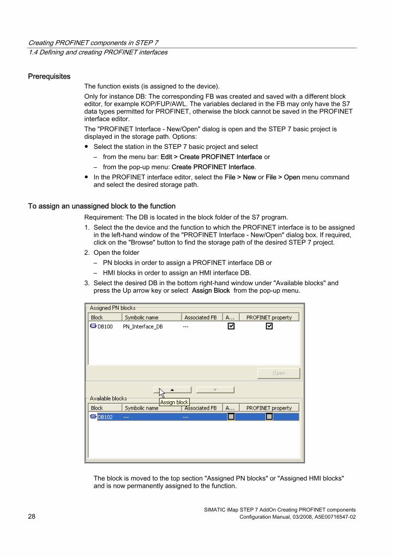
To assign an unassigned block to the function Requirement: The DB is located in the block folder of the S7 program. 1. Select the the device and the function to which the PROFINET interface is to be assigned
in the left-hand window of the "PROFINET Interface - New/Open" dialog box. If required, click on the "Browse" button to find the storage path of the desired STEP 7 project.
2. Open the folder – PN blocks in order to assign a PROFINET interface DB or – HMI blocks in order to assign an HMI interface DB.
3. Select the desired DB in the bottom right-hand window under "Available blocks" and press the Up arrow key or select Assign Block from the pop-up menu.
The block is moved to the top section "Assigned PN blocks" or "Assigned HMI blocks" and is now permanently assigned to the function.

Creating PROFINET components in STEP 7 1.4 Defining and creating PROFINET interfaces
SIMATIC iMap STEP 7 AddOn Creating PROFINET components Configuration Manual, 03/2008, A5E00716547-02 29
To cancel the assignment of a block to a function 1. Select the device and the function to which the PROFINET interface is to be assigned in
the left-hand window of the "PROFINET Interface - New/Open" dialog box. If required, click on the "Browse" button to find the storage path of the desired STEP 7 project.
2. Open the "Assigned PN blocks" or "Assigned HMI blocks" folder. 3. Select the desired DB in the top right-hand window and press the Down arrow key or
select Cancel assignment from the pop-up menu.
The block is moved to the bottom section under "Available blocks", is no longer active, but still retains its PROFINET property.
See also Adding a block (Page 25)

Creating PROFINET components in STEP 7 1.4 Defining and creating PROFINET interfaces
SIMATIC iMap STEP 7 AddOn Creating PROFINET components 30 Configuration Manual, 03/2008, A5E00716547-02
1.4.2.6 Open the interface DB in the PROFINET interface editor
Requirements For instance DB: The associated FB must have been created with a different editor (for example AWL/KOP/FUP). The "New/Open PROFINET Interface" dialog is open and the STEP 7 basic project is displayed in the storage path. The options are as follows: ● Select the station in the STEP 7 basic project and select
– from the menu bar: Edit > Create PROFINET Interface or – from the shortcut menu: Create PROFINET Interface.
● In the PROFINET interface editor, select the File > New or File > Open menu command and select the desired storage path.
The interface DB is assigned a function.
How to open a PROFINET interface DB 1. Select the device and the function whose PROFINET interface is to be opened in the left-
hand window of the "PROFINET Interface - New/Open" dialog box. If required, click on the "Browse" button to find the storage path of the desired STEP 7 project.
2. Open the "PN blocks" folder. 3. In the "Assigned PN blocks" select the desired block and then double-click or choose
from the Open block shortcut menu. Result: The block is opened in the PROFINET interface editor.
How to create an HMI interface DB 1. Select the device and the function whose HMI interface is to be opened in the left-hand
window of the "PROFINET Interface - New/Open" dialog box. If required, click on the "Browse" button to find the storage path of the desired STEP 7 project.
2. Open the "HMI blocks" folder 3. Select the desired block in the "Assigned HMI blocks" field and double-click on it or select
Open block from the shortcut menu. Result: The block is opened in the PROFINET Interface Editor.
Using an instance DB as a PROFINET interface DB or HMI interface DB If an instance DB is opened as an PROFINET interface DB or HMI interface DB in the PROFINET Interface-Editor, the variable declarations of the FB are converted as follows: Section in the FB Section in the interface DB IN PN_Input OUT PN_Output IN_OUT S7_Variable STAT S7_Variable
So what now? You edit the block in the PROFINET interface editor.

Creating PROFINET components in STEP 7 1.4 Defining and creating PROFINET interfaces
SIMATIC iMap STEP 7 AddOn Creating PROFINET components Configuration Manual, 03/2008, A5E00716547-02 31
1.4.2.7 Edit the global DB in the PROFINET interface editor A global DB can be directly edited in the PROFINET interface editor. I.e., you can add, move, delete or edit connectors.
Requirement The block is opened in the PROFINET interface editor.
How to edit a global DB in the PROFINET interface editor
With PROFINET interface DB: 1. In the "PN_Input" section, enter the connectors that are defined as inputs of the
technological function of the PROFINET component, and assign the necessary properties to the entries: name, data type, interconnectable, etc. Result: The interconnectable connectors appear in the graphical representation of the technological function (in the right-hand window of the interface editor).
2. In the "PN_Output" section, enter the connectors that are defined as outputs of the technological function of the PROFINET component, and assign the necessary properties to the entries: name, data type, interconnectable, etc. Result: The interconnectable connectors appear in the graphical representation of the technological function (in the right-hand window of the interface editor).
3. Optional: Enter the HMI connectors in the "S7_Variable" section. 4. Save the PROFINET interface DB created using the File > Save menu command.
With HMI interface DB: 1. Enter the HMI connectors in the "S7_Variable" section. 2. Save the created PROFINET interface DB using the menu command File > Save.
Note After being saved in the PROFINET interface editor, the global DB receives the property PROFINET interface if it does not exist yet. In the case of the PROFINET interface DB, after being saved, the block is marked as "active" if an active DB has not yet been assigned to the function.

Creating PROFINET components in STEP 7 1.4 Defining and creating PROFINET interfaces
SIMATIC iMap STEP 7 AddOn Creating PROFINET components 32 Configuration Manual, 03/2008, A5E00716547-02
Possible errors while opening interface DBs If the interface DB was first edited in another editor, errors may occur when the block is opened in the PROFINET interface editor, particularly if block attributes were modified, added or deleted. Incorrect entries cannot be assigned to a section while opening. Such entries are handled as follows: ● The incorrect entry is removed, and all subsequent entries for the data block are moved
to the "Unassigned" section. ● The incorrect entry is moved to the "Unassigned" section, together with all subsequent
entries for the data block. In both cases, an error message is displayed and you will have to move the connectors from the "Unassigned" section to the relevant sections.
1.4.2.8 Edit the instance DB in the PROFINET interface editor An instance DB cannot be directly edited in the PROFINET interface editor. The associated FB must have been previously edited and saved with a different block editor, for example KOP/FUP/AWL. In the PROFINET interface editor only specific properties of the connectors can be defined or changed: Initial value, interconnectable, HMI and MES.
Note The changes will be carried out on the FB itself and when saving the block they will be applied to all the associated instance DBs.
Requirement The block (associated FB of the instance DB) is opened in the PROFINET interface editor.
How to edit an instance DB in the PROFINET interface editor You cannot delete, add, copy or move connectors. You can only change the following properties of the connectors: ● HMI – If this property is activated, the variable is written in SIMATIC iMap to the HMI OPC
symbol file and can be used for HMI via OPC. ● MES – If this property is activated, the variable is written in SIMATIC iMap to the MES
OPC symbol file and can be used for MES via OPC. ● Read-Only - If this property is active, the variable is identified as read only in the OPC
symbol file. If the property is not active, the variable is identified as read and write in the OPC symbol file. Deactivate the option in the "Read-Only" column for the variables with read/write access.
● Initial value - you can define an initial value in the permissible range of the data type.

Creating PROFINET components in STEP 7 1.4 Defining and creating PROFINET interfaces
SIMATIC iMap STEP 7 AddOn Creating PROFINET components Configuration Manual, 03/2008, A5E00716547-02 33
1.4.2.9 Declaring simple data types
Requirement The block is opened in the PROFINET interface editor.
How to declare simple data type structures 1. Select a section from the variable overview. 2. Enter the name of the connector in the "Name" column of the variable detail view. 3. Press Enter. This confirms your input and inserts another blank line into the variable
declaration. You can now enter another name on the new line. The default settings in the "Data type", "Address" and "Initial value" columns may be changed if necessary.
Tip: Rapid entry Press Alt + Insert to quickly insert several variables one after another. If the initial letter of the name of the connector is entered and the enter key is pressed, the declaration line is automatically completed.
Syntax check A syntax check is performed after each entry, and any errors found are displayed in red. Therefore the initial value of a variable, for example, has to correspond to the specified data type. You do not have to correct these errors immediately you can continue editing and make any corrections later.
See also Data types of connectors (Page 120) Properties of the connectors (Page 17)

Creating PROFINET components in STEP 7 1.4 Defining and creating PROFINET interfaces
SIMATIC iMap STEP 7 AddOn Creating PROFINET components 34 Configuration Manual, 03/2008, A5E00716547-02
1.4.2.10 Declaring connectors with the data type ARRAY
Requirement The block is opened in the PROFINET interface editor.
How to declare connections of the ARRAY data type 1. In the "Data type" column, click on the selection box and select the data type ARRAY. 2. Then enter the required dimensions in the same column, with upper and lower limit, plus
the type of element, e.g. ARRAY [1..10] of Bool. Attention: There must be a space before and after "of".
3. If you wish to pre-assign certain values to the individual elements in the box, enter the desired values in the "Initial value" column.
Examples for entering initial values
Data type Initial value Explanation ARRAY[1..14] of Int 1234 The initial value 1234 is only assigned to the first ARRAY
element. All other elements in the field receive the initial value 0 (default for Int)
ARRAY[1..14] of Int 1234, 56, 78, 90 The initial values 1234, 56, 78, 90 are assigned in this order to the first four ARRAY elements. The remaining elements are given the value 0 (default for Int).
ARRAY[1..14] of Int 14 (9876) The initial value 9876 is assigned to all 14 ARRAY elements.
ARRAY[1..14] of Int 15 (4711) Error: More initial values were assigned than there are elements.
Rules ● Arrays with up to 6 dimensions can be declared. ● Arrays of string may only contain strings with an even-numbered length. ● The innermost dimension of an array of Bool in the form of an S7 variable must be a
multiple of 8. Example: Array [1..a, 1..b, ... 1..8*n] of Bool
See also Data types of connectors (Page 120) Properties of the connectors (Page 17)

Creating PROFINET components in STEP 7 1.4 Defining and creating PROFINET interfaces
SIMATIC iMap STEP 7 AddOn Creating PROFINET components Configuration Manual, 03/2008, A5E00716547-02 35
1.4.2.11 Declaring connectors with the data type STRUCT
Requirement The block is opened in the PROFINET interface editor.
To declare the connections with the data type Struct 1. In the "Data type" column, click on the selection box and select the STRUCT entry. An
element of the type Struct is generated. 2. Select the element from the variable overview and double-click. The structure is opened
and its content appears in the detail window. 3. You can now insert any number of variables into the structure.
Example The interface DB in the diagram below has an input of the type Struct.
Rule At most, 8-level structures can be declared.
See also Data types of connectors (Page 120) Properties of the connectors (Page 17)

Creating PROFINET components in STEP 7 1.4 Defining and creating PROFINET interfaces
SIMATIC iMap STEP 7 AddOn Creating PROFINET components 36 Configuration Manual, 03/2008, A5E00716547-02
1.4.2.12 Use of user-defined data types (UDT)
User-defined data types User-defined data types (UDTs) can be created with a language editor. UDTs have their own names, which means that they can be reused. For example, a user-defined data type can be used to generate several PROFINET interface data blocks with the same inputs or outputs.
To use a user-defined data type in a PROFINET interface 1. Open the block folder of the STEP 7 basic project in SIMATIC Manager. 2. Create a UDT with the menu command Insert > S7 block > data type. In the property
dialog, "General, part 1" tab, enter the names and, if required, further properties of the UDT.
3. Edit the UDT using a language editor and enter the names, types and initial values of the individual elements.
4. Save the UDT. 5. Open the PROFINET interface DB using the Edit > Create PROFINET interface menu
command. 6. In order to assign the UDT a specific connection, in the "Data type" box select UDT from
the list and enter the number of the UDT. Result: The UDT with he stipulated number is referenced in the interface DB. The elements of the UDT cannot be edited in the PROFINET interface editor.
Note Representation in SIMATIC iMap In the plant view of the SIMATIC Manager, the connections of type UDT are shown as STRUCT (refer to example).

Creating PROFINET components in STEP 7 1.4 Defining and creating PROFINET interfaces
SIMATIC iMap STEP 7 AddOn Creating PROFINET components Configuration Manual, 03/2008, A5E00716547-02 37
Example: Interface DB with UDT connection In the following diagram the output q2 has been assigned the user-defined data type UDT1.
Figure 1-5 Interface DB with UDT connection
Rules for using UDTs The rules for using UDTs in PROFINET interfaces are the same as for using other composite data types: In SIMATIC iMap only connections of the same type can be interconnected, i.e. the UDTs must have the same structure. Connections of type STRUCT and UDT can be interconnected with one another if they have the same structure.
See also Data types of connectors (Page 120) Properties of the connectors (Page 17)

Creating PROFINET components in STEP 7 1.4 Defining and creating PROFINET interfaces
SIMATIC iMap STEP 7 AddOn Creating PROFINET components 38 Configuration Manual, 03/2008, A5E00716547-02
1.4.2.13 Check CBA Consistency of All Active PN Blocks
PROFINET CBA consistency PROFINET interfaces must comply with certain rules, e.g. regarding the number and data length of the connectors, the data types used and the uniqueness of names. In the PROFINET interface editor, you can check whether the interface DB which is currently open complies with these consistency rules. The consistency of PROFINET CBA is automatically checked each time a block is saved in the PROFINET Interface Editor. The CBA consistency check for all active PN blocks of the device is performed with the menu command File > Check CBA Consistency of All Active PN Blocks.
How to check the CBA consistency of the PROFINET interface 1. Open the interface DB in the PROFINET interface editor. 2. Select the menu command File > Check CBA Consistency of All Active PN Blocks or click
on the "Check PROFINET CBA Consistency of All Active PN Blocks" icon. Result: Any errors are shown in a separate window.
3. Correct any errors and save the block.
Creating PROFINET components in STEP 7 1.4 Defining and creating PROFINET interfaces
SIMATIC iMap STEP 7 AddOn Creating PROFINET components Configuration Manual, 03/2008, A5E00716547-02 39
1.4.2.14 Check the block consistency
STEP 7 block consistency In the PROFINET interface editor, you can check whether time stamp conflicts occur and whether the consistency rules between calling and called blocks are complied with, e.g. between the FB and the associated instance DB.
How to check the STEP 7 block consistency of the interface DB, as in STEP 7 1. Open the interface DB in the PROFINET interface editor.
2. Select the menu command File > Check STEP 7 Block Consistency or click on the "Check STEP 7 Block Consistency" icon. This command has the same function as the "Check Block Consistency" command in SIMATIC Manager. Result: The result of the consistency check will be displayed in a separate window.
3. Correct any errors and save the block. For additional information on checking the STEP 7 block consistency, refer to the basic help for STEP 7.
1.4.2.15 Showing / hiding columns in the variable detail view
How to hide and show the columns 1. Select Show/Hide Columns from the pop-up menu or press the F11 key. 2. From the dialog box that appears, select the columns that you wish to show or hide. 3. Click on the "--->" or "<---" button. 4. Use the "Up" or "Down" button to change the order of the columns.
Tip: Save your new column layout To save the column layout for the current PROFINET interface and all further interfaces, select the "Save current column view as user default" option. You can save separate column settings for each section (PN_Input, PN_Output, etc). Every new object of the same type will then appear with your stored settings. You can also modify these settings during a session. You can also click on the "Default" button to restore the previously saved or system default column layouts.
Note If you modify the column settings for an object type and save it as a user default, this will only take effect on objects of this type that have not yet been opened. The original column settings will be retained by any objects of this type that are already open. To apply your new column settings to these objects as well, select Default > User.

Creating PROFINET components in STEP 7 1.4 Defining and creating PROFINET interfaces
SIMATIC iMap STEP 7 AddOn Creating PROFINET components 40 Configuration Manual, 03/2008, A5E00716547-02
1.4.2.16 Setting the column width in the variable detail view
How to set the column width Position the mouse pointer in the table header on the right-hand edge of the column, hold down the left mouse button and move the edge of the column in the desired direction. Double-click on the right-hand edge of a column to automatically set it to the optimum width. You can also use the F7 and F8 function keys to increase or reduce the size of columns.
Note There is a minimum size for columns. It is not possible to create smaller columns. To hide a column, select Show/Hide Columns from the pop-up menu.

Creating PROFINET components in STEP 7 1.4 Defining and creating PROFINET interfaces
SIMATIC iMap STEP 7 AddOn Creating PROFINET components Configuration Manual, 03/2008, A5E00716547-02 41
1.4.3 Changing the PROFINET interface
1.4.3.1 Modifying connectors This section describes the possible changes that you can make to the connectors of an open PROFINET interface DB.
NOTICE When you modify connectors, it is also possible to change the addresses of variables in the data block, so you will then have to adapt the program accordingly. Recommendation: Use symbolic names for the variables in the interface DB. In this way, you will make sure that the interface DB is independent of the physical addresses. To do this, make the following setting in SIMATIC Manager: In the object properties for the block folder, "Address Priority" tab, activate the option: "Symbol has priority for all accesses".
The procedure for copying and moving connectors is as follows: You can copy or move connectors anywhere, both within a section and between two sections. Using the mouse: ● To move the connector, highlight it, hold down the left mouse button and drag the
connector to the desired destination. ● To copy the connector, highlight it, hold down the left mouse button, press the CTRL
button and drag the connector to the desired destination. Using menu commands: 1. Click on the variable that you wish to copy. 2. Select the Edit > Copy or Edit > Cut menu command. 3. Open the declaration section in which you wish to save the copied or cut variable. 4. Select the Edit > Paste menu command.
Note When you copy a connector, a number is automatically appended to the name, thus "variable" will become "variable_1", for example.

Creating PROFINET components in STEP 7 1.4 Defining and creating PROFINET interfaces
SIMATIC iMap STEP 7 AddOn Creating PROFINET components 42 Configuration Manual, 03/2008, A5E00716547-02
How to delete a connector 1. Highlight the connector that you wish to delete. 2. Select the Edit > Delete menu command or press the Delete key.
How to change the data type 1. Click on the selection box in the "Data type" column. The selection depends on the
current block type and which section is selected. 2. Select one of the displayed data types. 3. Overwrite the default initial value, if necessary. Response in the "Initial value" column If the "Initial value" column still contained the default setting for the old data type, the default for the new data type is automatically entered here. If you have already entered an initial value that differs from the default, then the value you entered is retained. This is displayed in red if it is unsuitable for the new data type.
How to change the initial value Select the "Initial value" column from the variable detail view and enter a value. The initial value must conform to the specified data type.
Note There are no specific format rules for your input. If your input is clear, then the program will correct it to conform to the IEC standard. Invalid initial values are identified in red.
How to enter a comment Highlight a variable and enter a descriptive text in the "Comment" column. The comment may be up to 80 characters long.
See also Properties of the connectors (Page 17)

Creating PROFINET components in STEP 7 1.4 Defining and creating PROFINET interfaces
SIMATIC iMap STEP 7 AddOn Creating PROFINET components Configuration Manual, 03/2008, A5E00716547-02 43
1.4.3.2 Displaying properties You can display the properties of the following object types: ● entire PROFINET interface ● Section: PN_Input, PN_Output, S7_Variable, Unassigned ● Slot - DP_MasterOutputSlot, DP_MasterInputSlot, only for PROFIBUS devices (DP
slaves) with fixed functionality ● Connector
How to display online properties: 1. Click on the required icon in the tree structure in the variable overview. 2. Click the right mouse button and select the Object Properties menu command from the
pop-up menu.
See also PROFINET DB for DP slaves with fixed functionality (Page 46) Properties of the PROFINET interface (Page 12) Properties of the connectors (Page 17)
1.4.3.3 Activating and deactivating the PROFINET properties
Automatic assignment of PROFINET properties PROFINET properties are automatically assigned to a block when saved in the PROFINET interface editor: ● When a global DB is saved in the PROFINET interface editor, the DB automatically
receives the PROFINET property. ● When an instance DB is saved in the PROFINET interface editor, the DB and the
associated FB automatically receive the PROFINET property. If other instances DBs of the FB exist, they receive the same PROFINET properties.
You can see whether a DB PROFINET has properties in the "PROFINET Interface - New/Open" dialog. Blocks with PROFINET properties are marked in the " PROFINET properties" column (see example). The PROFINET properties are assigned to blocks in the form of attributes (see "User-defined attributes for PROFINET interfaces".
To assign PROFINET properties to a data block… In order to assign PROFINET properties to a data block, you have to open, edit and save the block in the PROFINET interface editor.

Creating PROFINET components in STEP 7 1.4 Defining and creating PROFINET interfaces
SIMATIC iMap STEP 7 AddOn Creating PROFINET components 44 Configuration Manual, 03/2008, A5E00716547-02
Example: Display of the PROFINET properties
To delete the PROFINET properties of an interface DB The block whose PROFINET properties you wish to deactivate may not be opened in the PROFINET interface editor.
Note When the PROFINET properties are deleted, the corresponding attributes of the block are removed (see "User-defined attributes for PROFINET interfaces").
To delete the PROFINET properties of an interface DB: 1. Select the File > Open menu command in the PROFINET interface editor. The
"New/Open PROFINET interface" dialog box opens. 2. In the left-hand window of the dialog box, select the station, device and the function to
which the block is assigned. 3. Select the desired block and remove the check mark from the "PROFINET properties"
column. 4. Click on the "OK" or "Apply" button.
To activate and deactivate an interface DB If several interface DBs are assigned to a function (in the "Assigned PN blocks" folder), only one of them may be active, i.e. is taken into account when the PROFINET component is created. The other assigned blocks can have PROFINET properties and may be used for other versions of the component. In this case, you can define the active interface DB by marking it in the "PROFINET Interface - New/Open" dialog in the "active" column. If an active interface DB is not yet assigned to the function, the first assigned DB (under "PN blocks") which is saved in the PROFINET interface editor automatically becomes the active interface DB and is marked in the column "active" (see example).
See also User-defined attributes for PROFINET interfaces (Page 122)

Creating PROFINET components in STEP 7 1.4 Defining and creating PROFINET interfaces
SIMATIC iMap STEP 7 AddOn Creating PROFINET components Configuration Manual, 03/2008, A5E00716547-02 45
1.4.3.4 Changing the PROFINET interface type
PROFINET interface types A PROFINET interface may contain two block types: ● PROFINET interface DB in the block folder "PN blocks" ● HMI interface DB in the block folder "HMI blocks"
Note For a PROFINET interface, all the instance DBs of an FB must be of the same type, either "PN block" or "HMI block".
If an interface type (PROFINET or HMI interface) is already assigned to a data block, you can change the interface type by canceling the existing assignment to the function, removing the PROFINET property of the block and reassigning the block to a function in the appropriate interface type.
To change the PROFINET interface type of a block 1. Open the "PROFINET Interface - New/Open" dialog box. Options:
– In the SIMATIC Manager: Select the station in the STEP 7 basic project and from the pop-up menu select Create PROFINET Interface.
– In the PROFINET interface editor: select the File > New or File > Open menu command and select the desired storage path.
2. Select the data block and cancel the assignment to the function. Press the Down arrow key or select Cancel assignment from the pop-up menu. The block is moved to the bottom section under "Available blocks", but still retains its PROFINET property.
3. Select the data block and remove the check mark from the "PROFINET properties" column.
4. Reassign the block to a function. Open the appropriate block folder for the new interface type. Select the desired DB in the right-hand window under "Available blocks" and press the Up arrow key or select Assign block from the pop-up menu. The block is moved to the top section "Assigned PN blocks" or "Assigned HMI blocks" and is now permanently assigned to the function. Note: With this operation, the block can optionally be assigned to the same function or a different function.
5. Open the data block and edit and save it in the PROFINET interface editor. As a result, the PROFINET property is assigned to the block.
See also Properties of the PROFINET interface (Page 12) Assigning a block to a function (Page 27) Activating and deactivating the PROFINET properties (Page 43)

Creating PROFINET components in STEP 7 1.4 Defining and creating PROFINET interfaces
SIMATIC iMap STEP 7 AddOn Creating PROFINET components 46 Configuration Manual, 03/2008, A5E00716547-02
1.4.4 Special cases of the PROFINET interfaces
1.4.4.1 PROFINET DB for DP slaves with fixed functionality
Introduction DP slaves with fixed functionality do not have their own user program. Thus, the interface DB only contains the interface definition. For the PROFINET component, you must create an interface DB for the DP slave and save it to the block folder of the S7 program assigned to the DP master station.
Assignment to the device In the case of PROFIBUS devices with fixed functionality, several DP slaves that are connected to a DP master in a SIMATIC 300 station (not 400) can be configured in a STEP 7 basic project. The PROFINET component is only created from the DP slave, the DP master is not part of the component. A PROFINET interface DB must be assigned to each slave from which a PROFINET component is to be created.
Structure of the interface DB for DP slaves with fixed functionality (e.g. standard slaves) For interface DBs for PROFIBUS devices with fixed functionality, the PN_Input and PN_Output sections are divided into slots. A slot corresponds to the slot in an input module or output module of the DP slave. The following applies to the structure of the interface DB: ● The output signals from the DP interface of the DP master are mapped onto slots in the
PN_Input section. The inputs of the technological function are defined in this section. ● The input signals for the DP interface of the DP master are mapped onto slots in the
PN_Output section. The outputs of the technological function are defined in this section.
Figure 1-6 Structure of the interface DB for DP slaves with fixed functionality

Creating PROFINET components in STEP 7 1.4 Defining and creating PROFINET interfaces
SIMATIC iMap STEP 7 AddOn Creating PROFINET components Configuration Manual, 03/2008, A5E00716547-02 47
Note A connection may not be declared beyond slot limits.
Data length of the connections For DP slaves with fixed functionality, the maximum permitted data length for a connection is exactly the same as the consistent length of the slot. Several connections can be declared within one slot. The data length of a connection can however not be greater than the data length of the slot for which it is defined. The maximum permitted data lengths and consistent lengths are specified in the object properties for the slot.
Note The input and output modules of the DP slave are automatically mapped onto slots in the structure of the interface DB. When saving the interface DB the adherence to the permissible data lengths of the connections is checked. In doing so, run-time errors in the plant caused by exceeding the consistency lengths are avoided.
Consistency length of the transferred data The consistent length of the transferred data is displayed in the slot properties in the PROFINET interface editor. Depending on the type of module, the consistent length may be configured in HW Config. Unless otherwise specified, the consistent length is generally: ● byte (8 bit) per digital input or output ● word (16 bit) per analog input or output This may be different for some modules. Detailed information can be found in the technical data for the module concerned.
Unique connection names The extension that is automatically added to the connection name, e.g. when you copy declarations, only ensures that the name is unique within a slot. The connection name is not checked for uniqueness within the entire interface DB until you save the interface DB.

Creating PROFINET components in STEP 7 1.4 Defining and creating PROFINET interfaces
SIMATIC iMap STEP 7 AddOn Creating PROFINET components 48 Configuration Manual, 03/2008, A5E00716547-02
Example: Interface DB for a PROFIBUS device, DP slave with fixed functionality, e.g. standard slave The PROFINET component is created only from one ET 200M with IM 153-1. The following diagram shows the hardware configuration and its representation on the structure of the PROFINET interface.
Figure 1-7 DP slave ET 200M with IM 153, hardware configuration

Creating PROFINET components in STEP 7 1.4 Defining and creating PROFINET interfaces
SIMATIC iMap STEP 7 AddOn Creating PROFINET components Configuration Manual, 03/2008, A5E00716547-02 49
Interface DB of the PROFINET component for IM153-1: ● the input module is mapped onto DPMasterInputSlot1 in the "PN_Output" section, ● the 2 output modules are mapped onto DPMasterOutputSlot1 and 2 in the "PN_Input"
section.
Figure 1-8 PROFINET interface for IM 153-1
In this example, the technological function contains 10 inputs and 10 outputs (including the lifestate output).

Creating PROFINET components in STEP 7 1.4 Defining and creating PROFINET interfaces
SIMATIC iMap STEP 7 AddOn Creating PROFINET components 50 Configuration Manual, 03/2008, A5E00716547-02
1.4.4.2 Creating internal HMI interface DBs Additional internal HMI interface DBs are possible in addition to the interface DB. These contain only non-interconnectable connectors that can be accessed via OPC using S7 protocols. An HMI interface DB may be assigned to either a PROFINET device or to a programmable PROFIBUS device.
Types of block used You can create an HMI interface DB from the following block types: ● Global data block (global DB) ● Instance data block of a function block
Requirements In the case of an instance DB, the declarations of the FB must have been inserted using a different editor e.g. KOP/FUP/AWL. In the PROFINET interface editor, only the necessary PROFINET properties are added to the existing declarations. The variables declared in the block may only have the S7 data types permitted for PROFINET, otherwise the block cannot be saved in the PROFINET interface editor.
How to create an HMI interface DB 1. Select the File > Open menu command in the PROFINET interface editor.
The "New/Open PROFINET interface" dialog box opens. 2. Select the the device and the function to which the HMI interface is to be assigned in the
left-hand window of the "PROFINET Interface - New/Open" dialog box. If required, click on the "Browse" button to find the storage path of the desired STEP 7 project.
3. Open the "Assigned HMI blocks" folder. 4. Add a new block or assign one of the available blocks to the function. 5. Select the desired block folder "Assigned HMI blocks" and open it by double-clicking on it.
Result: The block is opened in the interface editor. 6. Change the properties of the connectors as required (see below) 7. Save the block using the File > Save menu command. Result: The global or instance DB is created to extend the PROFINET interface and is taken into account the next time a PROFINET component is created.

Creating PROFINET components in STEP 7 1.5 Creating an S7 program
SIMATIC iMap STEP 7 AddOn Creating PROFINET components Configuration Manual, 03/2008, A5E00716547-02 51
Editing the HMI interface DB or FB in the PROFINET interface editor You cannot delete, add, copy or move connectors. You can only change the following properties of the connectors: ● HMI – If this property is activated, the variable is written to the OPC symbol file in
SIMATIC iMap and may be used for HMI via OPC. ● MES – If this property is activated, the variable is written to the OPC symbol file in
SIMATIC iMap and may be used for MES via OPC. ● Read-Only - If this property is active, the variable is identified as read only in the OPC
symbol file. If the property is not active, the variable is identified as read and write in the OPC symbol file. Deactivate the option in the "Read-Only" column for the variables with read/write access.
Deactivating and activating PROFINET properties When you deactivate the PROFINET properties of an HMI interface FB, all the associated instance DBs are automatically deactivated as well, and are thus ignored when the PROFINET component is created. When you reactivate the FB (by saving it in the PROFINET interface editor), an existing instance DB will not automatically be activated. You will have to create a new instance DB for the activated FB that inherits the activated PROFINET properties and is taken into account when the PROFINET component is created.
1.5 Creating an S7 program
Points to note when creating the S7 program... The S7 program for the future PROFINET component with programmable functionality is created in STEP 7 as usual. Take the following into consideration in this regard: ● Access to the inputs and outputs declared in the interface DB must be programmed in the
S7 program. ● Only for certain modules, e.g. for intelligent DP slaves: The necessary PROFINET copy
blocks must be located in the block folder for the S7 program. Make sure that these blocks are called correctly in the S7 program. Instructions can be found in the online help for the blocks (function key F1). The PROFINET copy blocks and other blocks for creating PROFINET components can be found in the PROFINET system library or in the STEP 7 standard library.
● The required interrupt and error OBs must also be programmed.

Creating PROFINET components in STEP 7 1.5 Creating an S7 program
SIMATIC iMap STEP 7 AddOn Creating PROFINET components 52 Configuration Manual, 03/2008, A5E00716547-02
PROFINET system library The PROFINET system library is located in the directory \s7libs\PROFINET of STEP 7.
Figure 1-9 Opening the PROFINET system library
Table 1-3 Contents of the PROFINET system library
Folder Contents: Blocks for... Device type CP 300 CP 300 for PROFINET CBA, e.g.
CP 343-1 PN, CP 343-1 Advanced PROFINET device
CP 400 CP 400 for PROFINET CBA, e.g. CP 443-1 Advanced
PROFINET device
CPU 300*) CPU 300 for PROFINET CBA, e.g. CPU 317-2 PN/DP, CPU 319-3 PN/DP
PROFINET device
CPU 400*) CPU 400 for PROFINET CBA, e.g. CPU 414-3 PN/DP, CPU 416-3 PN/DP
PROFINET device
I-DP slave Intelligent DP slaves PROFIBUS device with programmable functionality
WinLC PN*) Windows Logic Controller WinLC PN PROFINET device *) The optional copy blocks SFC 112, 113, and 114 for updating the PROFINET interface are located in S7 library "Standard Library".

Creating PROFINET components in STEP 7 1.5 Creating an S7 program
SIMATIC iMap STEP 7 AddOn Creating PROFINET components Configuration Manual, 03/2008, A5E00716547-02 53
To copy the blocks to the STEP 7 basic project Only for PROFINET components with programmable functionality: 1. In SIMATIC Manager, open the "PROFINET System Library“ with the menu command
File > Open in the "Libraries“ tab. 2. In the library, open the block folder corresponding to the device type of the PROFINET
component to be created, and copy all the blocks to the block folder of the basic project.
Tip Copy all the blocks of the corresponding device type (including the OBs) to the S7 program folder because they are required for creating the PROFINET component.
Detailed descriptions...
Note Detailed descriptions of how to program PROFINET components can be found in the "Commissioning Systems, Tutorial" manual, chapter "SIMATIC Devices as PROFINET Components". For detailed descriptions of the copy blocks of the CPU 31x-2 PN/DP and 41x-3 PN/DP, the CP 33x and 43x, and WinLC PN, refer to the relevant manuals and the context-sensitive help (F1) for the blocks.

Creating PROFINET components in STEP 7 1.6 Creating PROFINET Components
SIMATIC iMap STEP 7 AddOn Creating PROFINET components 54 Configuration Manual, 03/2008, A5E00716547-02
1.6 Creating PROFINET Components
1.6.1 Creating PROFINET components in SIMATIC Manager
Introduction If you wish to create PROFINET components from SIMATIC programmable controllers, you must do this using the STEP 7 SIMATIC Manager.
Requirement The STEP 7 basic project must be complete, i.e.: ● The hardware configuration and parameter settings for the modules are complete. ● The S7 program and the PROFINET interface DB have been created. ● The STEP 7 basic project has been tested. ● Optional: You have the documentation for the future PROFINET component. ● You have the files with the icons for representing the entire PROFINET component and
the associated device. If you do not have your own icon files for the component to be created, you can use the files supplied with the software, which are provided as defaults.
Rule You can create a PROFINET component from every station in the STEP 7 basic project in one of the following ways: ● From the entire station (CPU, intelligent DP slave) or ● From one of the DP slaves with fixed functionality on a SIMATIC 300 station (not 400).
Rule for DP slaves with fixed functionality To create the PROFINET component of a DP slave with fixed functionality (S7 slave or standard slave), a SIMATIC 300 station (not a SIMATIC 400 station) in which one CPU is configured with exactly one integrated PROFIBUS interface as DP master, e.g. CPU 315-2 DP, is required in the STEP 7 Basic project. The distributed I/O device whose PROFINET component is to be created must be configured as a DP slave on this DP master system. The SIMATIC 300 station must not contain additional PROFIBUS interfaces as the DP master, whether integrated interfaces or on PROFIBUS-CP because it is otherwise not possible to create the PROFINET component out of a DP slave.

Creating PROFINET components in STEP 7 1.6 Creating PROFINET Components
SIMATIC iMap STEP 7 AddOn Creating PROFINET components Configuration Manual, 03/2008, A5E00716547-02 55
How to create a PROFINET component in SIMATIC Manager 1. In your STEP 7 basic project, select the station from which the component is to be
created. 2. Select the Create PROFINET component menu command. There are two options:
– The Edit > Create PROFINET component menu command or – The context menu (right mouse button) Create PROFINET component.
Result: The "Create PROFINET component" dialog box opens. 3. Enter the properties of the PROFINET component to be created (see below). 4. Click on "OK" or "Cancel" to end your entries. If you click on "OK", the PROFINET
component is created. If you click on "Cancel", the dialog box closes without applying the changes in STEP 7.

Creating PROFINET components in STEP 7 1.6 Creating PROFINET Components
SIMATIC iMap STEP 7 AddOn Creating PROFINET components 56 Configuration Manual, 03/2008, A5E00716547-02
"General" tab This tab is used to define: ● which elements should be used to create the PROFINET component, e.g. the entire
station (a DP master/IO controller and one or more local DP slaves, if applicable, PROFINET IO devices and HMI devices) or an individual DP slave,
● Properties, such as name, device name, version, and identification of the component.
Figure 1-10 Creating the PROFINET component from a station

Creating PROFINET components in STEP 7 1.6 Creating PROFINET Components
SIMATIC iMap STEP 7 AddOn Creating PROFINET components Configuration Manual, 03/2008, A5E00716547-02 57
Figure 1-11 Creating the PROFINET component from a DP slave
Name The name and the device name must not exceed 24 characters and must start with a letter.
Version number The version contains four number strings, separated by dots. The first two places of the version number may be any numbers (up to 3 digits), the last two places are increased automatically. The version number entered must be higher than the previous.

Creating PROFINET components in STEP 7 1.6 Creating PROFINET Components
SIMATIC iMap STEP 7 AddOn Creating PROFINET components 58 Configuration Manual, 03/2008, A5E00716547-02
Identification of the PROFINET component The identification of the PROFINET component (Class-ID) is a unique identifier conforming to the COM standard. In SIMATIC iMap PROFINET components are identified by their class ID and version number. The options are as follows: ● If you select "New", a new identification is generated automatically. ● If you select "Retain", the default identification is retained. In this case, the PROFINET
component is only given a new version number. We recommend that you accept the default values ("Retain" option).
"Component Type" tab
Figure 1-12 "Component Type" tab
This tab is used to define the following: ● Which component type is to be created from the hardware configuration. ● How the PROFINET interface is to be updated at runtime.

Creating PROFINET components in STEP 7 1.6 Creating PROFINET Components
SIMATIC iMap STEP 7 AddOn Creating PROFINET components Configuration Manual, 03/2008, A5E00716547-02 59
Selecting the component type The options are as follows: ● Select the "Standard component" option to create a simple PROFINET component. We
distinguish between PROFINET components without or with proxy functionality. ● Select the "Singleton" option to create a Singleton component. This component type can
be created for any hardware configurations with an Ethernet connection. Additional information can be found under "Singleton components".
Standard component without proxy functionality Select this check box to create the PROFINET component from one of the following hardware configurations: ● SIMATIC station with PROFINET-compatible device, without proxy functionality, for
example, a 31x CPU with CP 343-1 PN. The PROFINET component you created has one PROFINET device.
● From a SIMATIC station with a CPU that is configured as a DP slave and contains the necessary blocks in the S7 program. The PROFINET component you created has one PROFIBUS device with programmable functionality (intelligent DP slave).
● From a DP slave only, and not from the entire station. The PROFINET component you created has one PROFIBUS device (DP slave) with fixed functionality.
Standard component with proxy functionality Check this check box if the created PROFINET component is to contain a PROFINET device with proxy functionality. This component type can only be created for hardware configurations with the following features: ● The station contains a PROFINET-compatible device with proxy functionality, for
example, a CPU with integrated PN/DP interface or WinLC PN. ● The station has one or more configured DP master systems.
Updating the PROFINET interface The PROFINET interface is updated at runtime as follows: ● "Using the user program (copy blocks)"- This option can only be selected for
programmable PROFINET devices. The copy blocks must be copied from the PROFINET system library or standard library to the block folder for the STEP 7 basic project. Information about the copy blocks can be found in the context help (F1) for the blocks and in the descriptions of the PROFINET devices and PROFIBUS devices.
● "Automatically (at the scan cycle checkpoint)"– (i.e. at the time the process image is updated). This is the default setting that is supported for most PROFINET devices and for all PROFIBUS devices (DP slaves) with fixed functionality.

Creating PROFINET components in STEP 7 1.6 Creating PROFINET Components
SIMATIC iMap STEP 7 AddOn Creating PROFINET components 60 Configuration Manual, 03/2008, A5E00716547-02
"DP Subnets" tab
Figure 1-13 "DP Subnets" tab
Here you can configure up to four PROFIBUS connections of the component. This tab is only displayed if the hardware and network configuration allows it.

Creating PROFINET components in STEP 7 1.6 Creating PROFINET Components
SIMATIC iMap STEP 7 AddOn Creating PROFINET components Configuration Manual, 03/2008, A5E00716547-02 61
"Functions" tab
Figure 1-14 "Functions" tab
This is where the function or the part functions that form the PROFINET interface of the component as well as the assigned interface block are shown.
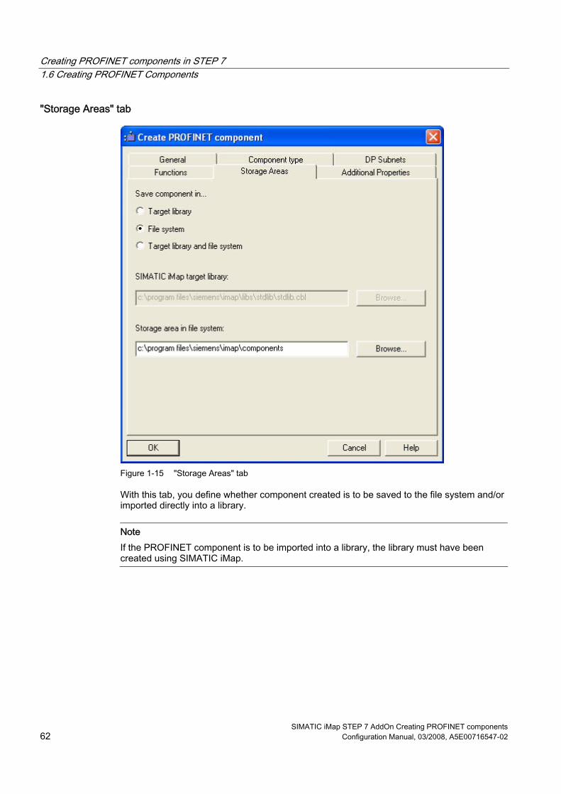
Creating PROFINET components in STEP 7 1.6 Creating PROFINET Components
SIMATIC iMap STEP 7 AddOn Creating PROFINET components 62 Configuration Manual, 03/2008, A5E00716547-02
"Storage Areas" tab
Figure 1-15 "Storage Areas" tab
With this tab, you define whether component created is to be saved to the file system and/or imported directly into a library.
Note If the PROFINET component is to be imported into a library, the library must have been created using SIMATIC iMap.

Creating PROFINET components in STEP 7 1.6 Creating PROFINET Components
SIMATIC iMap STEP 7 AddOn Creating PROFINET components Configuration Manual, 03/2008, A5E00716547-02 63
"Additional Properties" tab With this tab you define ● which icons should be assigned to the PROFINET component and the PROFINET device
and ● the path name or Internet address under which the documentation for the PROFINET
component can be found.
Figure 1-16 "Additional Properties" tab
The icon for the technological function was already defined in the object properties of the function in the PROFINET interface editor, dialog "PROFINET Interface - New/Open".

Creating PROFINET components in STEP 7 1.6 Creating PROFINET Components
SIMATIC iMap STEP 7 AddOn Creating PROFINET components 64 Configuration Manual, 03/2008, A5E00716547-02
Note Documentation link If you enter the documentation link as the URL, you must make sure that the documentation is actually accessible on the system. A documentation link can only reference a single file. If an HTM file containing cross-references to other files is specified when the PROFINET component is created, only the specified HTM file is copied to the PROFINET component folder - not the referenced files. Remedy: We recommend that you use a different format, e.g. PDF or CHM, if you require complex documents.
Result The PROFINET component is stored as a directory at the specified storage area – in the file system or directly in the library, or at both locations. The directory name contains the names, the identification (class ID) and the version number of the PROFINET component. The directory contains the following: ● The XML file containing the description of the PROFINET component and, in particular,
the technological function. The system searches for this XML file when importing to a library.
● The icon files. ● The archived STEP 7 component project that contains a copy of the station or the DP
slave from the basic project. ● The file for the documentation link, if a path name in the file system was specified as the
documentation link.
See also Importing PROFINET components to a library (Page 66) Naming conventions for PROFINET components (Page 118) Creating multi-function components (Page 107)

Creating PROFINET components in STEP 7 1.6 Creating PROFINET Components
SIMATIC iMap STEP 7 AddOn Creating PROFINET components Configuration Manual, 03/2008, A5E00716547-02 65
1.6.2 Version numbers of PROFINET components
Application Every PROFINET component has a version number that forms a unique identifier for the component together with the identification (class ID). This ensures that a newly created PROFINET component does not accidentally overwrite an earlier issue of the component.
Structure of the Version Number The version contains four series of numbers, separated by dots. ● The first two places of the version number may be assigned as required (up to 3 digits)
e.g. 01.04 ● The last two places of the build version cannot be modified and are incremented
automatically.
Figure 1-17 Structure of the Version Number
Rules When you enter a version number, it must always be higher than the previous number. You can change the first two parts or leave them unchanged. If you change them, you are asked whether the last two parts should be reset to 0 or incremented.
Automatically incrementing the version number The last two parts of the version number are automatically incremented as follows: ● The last part (minor build version) is incremented by one whenever a new version of the
PROFINET component is successfully created. ● The penultimate part (major build version) is incremented by one whenever the interface
DB is changed. The last part is automatically set to 0. This applies to both the PROFINET interface DB and to any internal HMI interface DB.
Note These changes are only applied if the PROFINET component was created successfully. If creation is canceled, the version number remains unchanged.

Creating PROFINET components in STEP 7 1.7 Importing PROFINET components to a library
SIMATIC iMap STEP 7 AddOn Creating PROFINET components 66 Configuration Manual, 03/2008, A5E00716547-02
1.7 Importing PROFINET components to a library
Basic Procedure A PROFINET component must be located in a library before it can be inserted into SIMATIC iMap. You can insert a PROFINET component into a library in the following ways: ● When you create the PROFINET component in the device-specific programming and
configuration tool, e.g. SIMATIC Manager ● In SIMATIC iMap, by importing to a library (described in the SIMATIC iMap Help topics
under "Configuring a plant, Importing PROFINET components").
Requirement If you create a PROFINET component and wish to import it, then the library must have been created using SIMATIC iMap.
How to import the PROFINET component directly during creation 1. In SIMATIC Manager, select the station for the component to be created. 2. From the pop-up menu, select Create PROFINET component. 3. In the "Create PROFINET component" dialog box, "Storage areas" tab, select one of the
following options: – "Target library" or – "Target library and file system".
4. Accept the default library in the "SIMATIC iMap target library" box or click on the "Browse" button to look for another library in the file system. In the "Select" box, navigate to the library folder, highlight the file with the extension .cbl and click on OK to confirm.
5. On the other tabs of the dialog box, enter any settings you wish to make and click on OK to confirm.
Result: The PROFINET component is created in the specified folder in the library (and in the file system, if necessary).

Creating PROFINET components in STEP 7 1.8 Modifying PROFINET components
SIMATIC iMap STEP 7 AddOn Creating PROFINET components Configuration Manual, 03/2008, A5E00716547-02 67
1.8 Modifying PROFINET components
Modification options The options for modifying existing PROFINET components are as follows: ● Edit the original STEP 7 basic project in SIMATIC Manager.
or ● Revise a PROFINET component directly in the library in SIMATIC iMap. This operation is
described in the SIMATIC iMap documentation under "Configuring plants, Working with modified PROFINET components".
In both cases, you will have to modify the associated STEP 7 project in SIMATIC Manager and then recreate the PROFINET component.
Procedure for editing a STEP 7 basic project To modify an existing PROFINET component: 1. Open the STEP 7 basic project in SIMATIC Manager. 2. Make your changes to the program or hardware configuration. 3. If necessary, compile the program changes and save the STEP 7 project (and hardware
configuration, if necessary). 4. Create a new PROFINET component from the modified station or DP slave. Select the
Edit > Create PROFINET component menu command. Note: The dialog box contain the default properties that were used when the last component was created.
5. If necessary, modify the properties of the PROFINET component, such as the name, version or storage area.
6. Click on "OK" to confirm. 7. If you´ve only stipulated the file system (no library) as the storage area: Import the
created PROFINET component into a SIMATIC iMap library. You can then use the modified PROFINET component in a SIMATIC iMap project.

Creating PROFINET components in STEP 7 1.8 Modifying PROFINET components
SIMATIC iMap STEP 7 AddOn Creating PROFINET components 68 Configuration Manual, 03/2008, A5E00716547-02

SIMATIC iMap STEP 7 AddOn Creating PROFINET components Configuration Manual, 03/2008, A5E00716547-02 69
SIMATIC devices as PROFINET components 22.1 SIMATIC devices - Overview
Device types in PROFINET CBA SIMATIC programmable controllers are integrated in PROFINET CBA communication as PROFINET components. From the perspective of communication integration in PROFINET CBA, a distinction is made between the following device types: ● PROFINET devices ● PROFIBUS devices
PROFINET device A PROFINET device always has an Ethernet connector. A PROFINET device may also have a PROFIBUS connector as a proxy master for PROFIBUS devices.
PROFIBUS device A PROFIBUS device has just one PROFIBUS connector and is always a slave. It does not participate directly in PROFINET communication and is integrated via a PROFINET device with proxy functionality.
Programmable and fixed functionality We differentiate between PROFINET components: ● with programmable functionality
These components have their own S7 program which can be downloaded from SIMATIC iMap to the module (e.g. to a CPU or WinLC PN).
● with fixed functionality These components do not have their own S7 program, e.g. ET 200M or IE/PB Link.

SIMATIC devices as PROFINET components 2.1 SIMATIC devices - Overview
SIMATIC iMap STEP 7 AddOn Creating PROFINET components 70 Configuration Manual, 03/2008, A5E00716547-02
SIMATIC devices that can be used You can create PROFINET components from the following SIMATIC devices: ● Central processing units with central and distributed peripherals as PROFINET devices or
PROFIBUS devices with programmable functionality ● PCs with Windows Logic Controller for PROFINET (WinLC PN) as a PROFINET or
PROFIBUS device with programmable functionality ● "Intelligent" DP slaves (I slaves) as PROFIBUS devices with programmable functionality ● DP slaves as PROFIBUS devices with fixed functionality
Configuring in STEP 7 PROFINET components of the SIMATIC devices are created from STEP 7 projects in SIMATIC Manager. The following features are important: ● Station in the SIMATIC Manager
The device from which the PROFINET component is created may be located in a separate station (e.g. a CPU or WinLC PN), or it may be configured as a DP slave with fixed functionality (e.g. ET 200M) on a DP master system of a SIMATIC-300 station. In the second case, the DP master is not part of the PROFINET component to be created.
● Network connectors The network connectors of the devices can be seen in the SIMATIC iMap network view PROFIBUS devices used as DP slaves have only one PROFIBUS connector. PROFINET devices have the following network connectors: – a connector for Industrial Ethernet and – optionally 1 to 4 connectors for PROFIBUS DP as the DP master with proxy
functionality for PROFIBUS devices (depending on the device type). ● local subnets (internal networking)
In addition to the above-mentioned network connectors, central modules, such as CPUs or WinLC PN, may also be networked internally. e.g. with local PROFINET IO systems, local PROFIBUS DP master systems or an MPI bus. The internally networked devices, such as the local DP slaves, are part of the PROFINET component, but still do not appear in SIMATIC iMap and are not involved in PROFINET CBA communication. For additional information, please refer to the chapter "Hardware and network configurations."
● Programming - Blocks required The block folder of the S7 program must contain the following blocks which, in turn, contain the interface declaration for the technological function. – one interface DB for each function - for all PROFINET components that contain one or
more technological functions – Additional blocks, e.g. copy blocks for intelligent DP slaves
Information on the blocks can be found in the descriptions of the individual device types.

SIMATIC devices as PROFINET components 2.1 SIMATIC devices - Overview
SIMATIC iMap STEP 7 AddOn Creating PROFINET components Configuration Manual, 03/2008, A5E00716547-02 71
Example: Representation of devices in SIMATIC iMap The following table shows sample displays of the devices and their network connectors in the network view of SIMATIC iMap.
Network connectors Representation in SIMATIC iMap PROFINET device on the Industrial Ethernet
PROFINET device on the Industrial Ethernet and DP master on the PROFIBUS (proxy functionality)
PROFIBUS device DP slave on the PROFIBUS
The internal networking of the devices, e.g. a local PROFIBUS, cannot be seen in SIMATIC iMap

SIMATIC devices as PROFINET components 2.2 Hardware and network configurations for PROFINET devices
SIMATIC iMap STEP 7 AddOn Creating PROFINET components 72 Configuration Manual, 03/2008, A5E00716547-02
2.2 Hardware and network configurations for PROFINET devices
2.2.1 Configurations for PROFINET devices
Supported devices A PROFINET device may be one of the following SIMATIC devices: ● S7-300 and S7-400 central modules with integrated PROFINET interface
Central modules with integral PROFINET interface are PROFINET devices with optional proxy functionality. Local DP slaves and/or one or more local HMI devices may also be connected to the PROFIBUS. The PROFINET interface can optionally also be used as for PROFINET IO. Examples: CPU 319-3 PN/DP, CPU 416-3 PN/DP
● S7-300 and S7-400 central module with a PROFINET-compliant communication processor (PROFINET CP), such as the CP 343-1 Advanced or CP 443-1 Advanced If a PROFINET CP is used for CBA, the PROFINET device of the central module has no proxy functionality, but it can run local subnets such as PROFINET IO, PROFIBUS DP master systems or a local MPI bus.
● Windows Logic Controller WinLC PN The WinLC PN is a PROFINET device with proxy functionality. Local DP slaves and/or local HMI devices may also be connected to the PROFIBUS.
● Network transition IE/PB Link The IE/PB Link is a PROFINET device with proxy functionality, but no local DP slaves may be connected to it.
● Further hardware configurations with Ethernet connectors as singleton components (see "Singleton components").
Network connections PROFINET devices may have the following network connections: ● Industrial Ethernet ● PROFIBUS (DP master with proxy functionality) ● Network connections for local subnets

SIMATIC devices as PROFINET components 2.2 Hardware and network configurations for PROFINET devices
SIMATIC iMap STEP 7 AddOn Creating PROFINET components Configuration Manual, 03/2008, A5E00716547-02 73
Industrial Ethernet connection Each PROFINET device has exactly one Industrial Ethernet connection which is shown as an Ethernet network connection in SIMATIC iMap. This network connection can be used as follows: ● Exclusively for PROFINET CBA
The connector may not be networked in HW Config, it is networked in SIMATIC iMap via PROFINET CBA.
● For PROFINET CBA and PROFINET IO The device is also a PROFINET IO controller with a separate PROFINET IO system. Several PROFINET IO devices which are part of the PROFINET component may be connected to it. In SIMATIC iMap, the network connection is networked via PROFINET CBA. The PROFINET IO system and the associated IO devices cannot be seen in SIMATIC iMap, but they must receive their own IP addresses in SIMATIC iMap. (See also "PROFINET components with PROFINET IO controllers").
PROFIBUS connectors as the DP master with proxy functionality Depending on the device type, PROFINET devices can optionally have 1 to 4 PROFIBUS connectors as the DP master with proxy functionality (proxy PROFIBUS connectors). These connectors may only be configured on integrated PROFIBUS interfaces. In the network view of SIMATIC iMap they are used to connect PROFIBUS devices. If more than 4 DP master systems are configured on integrated interfaces, when you create the PROFINET component you can define which of them are to be shown as the DP master with proxy functionality in SIMATIC iMap. Local DP slaves may be configured on the proxy PROFIBUS connectors (see below "locally connected devices").
Network connections for local subnets In addition to the above-mentioned network connections, depending on the device type, PROFINET devices may optionally have further network connections: ● One or more PROFIBUS connectors for local DP master systems ● One or more Industrial Ethernet connectors for local PROFINET IO systems ● One MPI connector The locally connected devices of a PROFINET device are not visible in SIMATIC iMap and are not involved in PROFINET CBA communication.

SIMATIC devices as PROFINET components 2.2 Hardware and network configurations for PROFINET devices
SIMATIC iMap STEP 7 AddOn Creating PROFINET components 74 Configuration Manual, 03/2008, A5E00716547-02
Devices locally connected to PROFIBUS DP master systems Local DP master systems can be configured on both PROFIBUS CPs (e.g. CP 342-5) and integrated PROFIBUS connectors. The following devices can be connected to local PROFIBUS DP master systems: ● Intelligent DP slave ● DP standard slaves ● DP S7 slaves ● DP ASI links ● DP PA links ● HMI devices The PROFIBUS addresses of the local DP slaves on the proxy PROFIBUS are regarded as assigned in SIMATIC iMap. The PROFIBUS addresses on the local DP master systems which are not defined as proxy PROFIBUS do not have any meaning in SIMATIC iMap (see below "Sample configuration of a PROFINET device with S7 300-CPU"). If the local PROFIBUS of a CPU is structured via a PROFIBUS CP, no local intelligent DP slaves may be connected to it. The intelligent DP slaves on the local DP master system can, in turn, each run one or more local PROFIBUS connectors as the DP master. However, no further intelligent DP slaves may be connected to these local PROFIBUS connectors.
Note Connecting S7 slaves Not every DP master can run S7 slaves. This information can be found in the relevant manuals.
Note
Program download When a program is downloaded to the PROFINET device from SIMATIC iMap, the programs for the associated local intelligent DP slaves are automatically downloaded as well, if the local DP slaves are connected.
Note
Isochrone components Isochrone components can only be connected to a local PROFIBUS.
Locally connected PROFINET IO devices The locally connected IO devices cannot be seen in SIMATIC iMap and are irrelevant for PROFINET CBA communication. The device names and IP addresses of the locally connected PROFINET IO devices are, however, configured in SIMATIC iMap. When a program is downloaded from SIMATIC iMap to the PROFINET IO controller, the IP addresses of the associated IO devices are downloaded as well.

SIMATIC devices as PROFINET components 2.2 Hardware and network configurations for PROFINET devices
SIMATIC iMap STEP 7 AddOn Creating PROFINET components Configuration Manual, 03/2008, A5E00716547-02 75
Devices connected locally to MPI Only HMI devices can be connected to the local MPI bus of a PROFINET device.
Locally connected HMI devices See chapter "HMI devices in PROFINET components".
Sample configuration of a PROFINET device with S7 300-CPU with integrated PROFINET interface The hardware configuration constitutes the PROFINET component of a PROFINET device with 2 PROFIBUS connectors as the DP master with proxy functionality, a local DP master system and integrated PROFINET IO system.
Table 2-1 Key
Network connection Description Integrated interface X1: PROFIBUS_Proxy1
PROFIBUS DP master with proxy functionality (proxy PROFIBUS can be seen in SIMATIC iMap, for connecting PROFIBUS devices)
Integrated interface X2: PROFIBUS_Proxy2
PROFIBUS DP master with proxy functionality (proxy PROFIBUS can be seen in SIMATIC iMap, for connecting PROFIBUS devices) 2 local DP slaves connected. The PROFIBUS addresses of these devices are regarded as assigned in SIMATIC iMap.
Integrated interface X3: CBA-PN-IO
Industrial Ethernet connector, both for PROFINET CBA and PROFINET IO 2 local PROFINET IO devices connected
Slot 4: PROFIBUS CP 342-5, local DP master system with 2 local DP slaves. The PROFIBUS addresses of these devices have no meaning in SIMATIC iMap.

SIMATIC devices as PROFINET components 2.2 Hardware and network configurations for PROFINET devices
SIMATIC iMap STEP 7 AddOn Creating PROFINET components 76 Configuration Manual, 03/2008, A5E00716547-02
Sample configuration of a PROFINET device with S7 400 CPU and PROFINET CP The hardware configuration constitutes the PROFINET component of a PROFINET device with a local DP master system and 2 integrated PROFINET IO systems.
Table 2-2 Key
Network connection Description Integrated DP interface X2: Local PROFIBUS DP master system with 2 local DP slaves Slot 6: CP 443-1 Advanced:
Industrial Ethernet connector, both for PROFINET CBA and PROFINET IO. The option "Use this module for PROFINET CBA" is activated in the object properties of CP 442-1 Adv 1, "PROFINET" tab. 3 local PROFINET IO devices connected. The IP addresses of these devices are assigned in SIMATIC iMap.
Slot 7: CP 443-1 Advanced
Industrial Ethernet connector, only for PROFINET IO 2 local PROFINET IO devices connected. These devices are only configured via STEP 7.
See also HMI devices in PROFINET components (Page 102) PROFINET components with PROFINET IO controllers (Page 86)

SIMATIC devices as PROFINET components 2.2 Hardware and network configurations for PROFINET devices
SIMATIC iMap STEP 7 AddOn Creating PROFINET components Configuration Manual, 03/2008, A5E00716547-02 77
2.2.2 Central processing units - Configuration options
Central modules as PROFINET and PROFIBUS devices A CPU from the SIMATIC S7-300/S7-400 product family always creates a PROFINET component with programmable functionality. CPUs may be used as: ● PROFINET devices (with an Ethernet connector) ● Intelligent PROFIBUS devices (with a PROFIBUS connector as a DP slave) The station forms a unit with one or more defined functions, such as a machining station or coordinator. The PROFINET component generally consists of a technological function and the associated device.
See also Central processing units as PROFINET devices (Page 77) Central processing units as PROFIBUS devices (Page 95)
2.2.3 Central processing units as PROFINET devices
Configuration options PROFINET components with an Ethernet connection for PROFINET CBA can be created from all central modules of the SIMATIC 300 and 400 product families: Central modules of the type CPU 31x-2/3 PN/DP and CPU 41x-3 PN/DP have an integral PROFINET interface and are therefore PROFINET-compliant. Other types of CPU have to be combined with a PROFINET-compliant communication processor (PROFINET-CP), such as: ● CP 343-1 Advanced - for CPUs of the SIMATIC 300 product family ● CP 443-1 Advanced - for CPUs of the SIMATIC 400 product family Optionally, the SIMATIC 300/400 station may contain the associated central and distributed I/O devices, see "Configurations for PROFINET devices".
Note Configurations with several CPUs (multicomputing) are only possible in singleton components.

SIMATIC devices as PROFINET components 2.2 Hardware and network configurations for PROFINET devices
SIMATIC iMap STEP 7 AddOn Creating PROFINET components 78 Configuration Manual, 03/2008, A5E00716547-02
Updating of the PROFINET interface for central modules with integrated PN/DP interface When you create the PROFINET component for a central module with integrated PN/DP interface, you have two ways to update the PROFINET interface at runtime: ● Automatically at the scan cycle checkpoint, i.e. at the time the process image is
refreshed. ● Via a user program using copy blocks (SFCs 112, 113 and 114).
You will have to copy the copy blocks from the STEP 7 standard library to the block folder for the STEP 7 basic project and call them in the S7 program.
Block Description SFC 112 PN_IN - Updates the inputs of the interface DB of the PROFINET component SFC 113 PN_OUT - Copies the data from the outputs of the interface DB to the CPU
memory area SFC 114 PN_DP – Updates the DP interconnections in the proxy system and the local
DP interconnections
In STEP 7 in, information on the blocks can be found the help on system functions / function blocks.
If a PROFINET CP is used... The following is to be taken into account: ● Hardware configuration:
Depending on the device type, several PROFINET CPs can be configured in a SIMATIC 300 station, however only one of them may be configured for PROFINET CBA . Depending on the device type, several PROFINET CPs may be configured in the central rack in a SIMATIC 400 station, however only exactly one of them may be configured for PROFINET CBA . Stations with central modules with an integrated PROFINET interface cannot contain PROFINET CPs that are configured for PROFINET CBA if the integrated PROFINET interface of the CPU is configured for CBA.
● Configuration for standard components: When you configure the Ethernet port, you must: – Select the "IP address is used" option – Clear the "Set MAC address / Use ISO protocol" option
● Networking of CPs with multiple Ethernet interfaces If more than one Ethernet/PROFINET interface of the CP is networked and a standard PROFINET component is created from the configuration, you must note the following when using the component in SIMATIC iMap. Make sure that the IP addresses assigned to the instances of the PROFINET component are not in the same subnet as the IP address of the second networked interface (e.g., gigabit interface). This interface is not visible in SIMATIC iMap. If, however, the IP address you assigned in HW Config is located in the same subnet as the IP address that was assigned to the instance of the component in SIMATIC iMap, the instance cannot be generated in SIMATIC iMap.

SIMATIC devices as PROFINET components 2.2 Hardware and network configurations for PROFINET devices
SIMATIC iMap STEP 7 AddOn Creating PROFINET components Configuration Manual, 03/2008, A5E00716547-02 79
● Copy block in the S7 program: The FB 88 function block (PN_InOut) or FB 90 function block (PN_InOut_FAST) must be called in the program on the CPU. This function block is a PROFINET copy block. It transfers the data from the interface DB to the PROFINET CP and from the PROFINET CP to the interface DB. The FB 88/FB 90 must be copied from the PROFINET system library to the block folder for the STEP 7 basic project. For additional information, refer to the help relating to the blocks and the device manuals for the CPs.
Examples: Central modules as PROFINET devices
Table 2-3 Example configurations:
Hardware configuration Technological function Device PROFINET device with 2 PROFIBUS connections as the DP master with proxy functionality, a local DP master system and integrated PROFINET IO system.
CPU 319-3 PN/DP

SIMATIC devices as PROFINET components 2.2 Hardware and network configurations for PROFINET devices
SIMATIC iMap STEP 7 AddOn Creating PROFINET components 80 Configuration Manual, 03/2008, A5E00716547-02
Hardware configuration Technological function Device PROFINET device with a PROFIBUS connection as the DP master with proxy functionality, a local DP master system and integrated PROFINET IO system.
CPU 416-3 PN/DP
PROFINET device without proxy functionality, with a local DP master system and 2 integrated PROFINET IO systems.
CPU 417-4 with CP 443-1 Advanced
See also Central processing units as PROFIBUS devices (Page 95)

SIMATIC devices as PROFINET components 2.2 Hardware and network configurations for PROFINET devices
SIMATIC iMap STEP 7 AddOn Creating PROFINET components Configuration Manual, 03/2008, A5E00716547-02 81
2.2.4 WinAC PN Option (WinLC PN)
PROFINET-compliant The WinAC PN Option V4.1 software enables WinLC to support PROFINET CBA and to participate in PROFINET communication as a direct node. WinLC with PROFINET functionality represents a PROFINET-compliant device. It always constitutes a PROFINET component with programmable functionality, i.e., with its own control program.
Hardware setup In order to use SIMATIC iMap to integrate WinLC in PROFINET communication, a PROFINET component must be created with STEP 7. You can create a PROFINET component for WinLC from a SIMATIC PC station containing the following hardware configuration: ● A WinLC controller with ● An Industrial Ethernet CP, plus ● Locally distributed I/O (optional), e.g., via CP 5613 or CP 5611 ● optionally one or more integral HMI devices on the local PROFIBUS, in the PC station or
on the Industrial Ethernet The local DP slaves and HMI devices cannot be seen on the PROFINET component in SIMATIC iMap. The station constitutes a unit with one or more defined functions, usually a centralized control function.
Network connections A WinLC with the above configuration that is acting as a PROFINET component has two network connections, each with: ● Industrial Ethernet ● PROFIBUS DP in the form of a DP master with proxy functionality using CP 5613 or
CP 5611 (optional).
Communication via Industrial Ethernet To operate WinLC on Industrial Ethernet, you must have either a standard Ethernet card, e.g., 3COM card, or a CP 161x in the PC station, as well as the associated software and its license (SIMATIC NET from V6.2).

SIMATIC devices as PROFINET components 2.2 Hardware and network configurations for PROFINET devices
SIMATIC iMap STEP 7 AddOn Creating PROFINET components 82 Configuration Manual, 03/2008, A5E00716547-02
Communication via PROFIBUS DP In order to operate WinLC on PROFIBUS DP, you must insert a CP (communications processor) in the PC for the connection to PROFIBUS DP. Only the following CPs are suitable for this purpose: ● CP 5611 or ● CP 5613 Likewise, you can use the CP integrated in SIMATIC PGs/PCs to connect to PROFIBUS DP.
Proxy functionality WinLC can be configured as a PROFINET device with or without proxy functionality. As a PROFINET device with proxy functionality, WinLC can also serve as a linking element for DP slaves that are not PROFINET-compliant. Examples include distributed I/O devices such as ET 200S or ET 200X, which do not support the PROFINET standard. However, these devices can be integrated in Component Based Automation in the form of PROFINET components. You can use STEP 7 to create the PROFINET components for these devices and then link these PROFINET components to WinLC, thereby integrating them in PROFINET communication. WinLC thus acts as a proxy for DP slaves which do not support the PROFINET standard. The figure below shows a WinLC configured as a PROFINET device with proxy functionality and the coupled PROFIBUS devices in SIMATIC iMap.
Figure 2-1 WinLC with proxy functionality in SIMATIC iMap

SIMATIC devices as PROFINET components 2.2 Hardware and network configurations for PROFINET devices
SIMATIC iMap STEP 7 AddOn Creating PROFINET components Configuration Manual, 03/2008, A5E00716547-02 83
Note In order to use WinLC as a DP master with proxy functionality, the PROFIBUS CP must be configured as a submodule on an IF slot. For detailed information on configuring a submodule, refer to the section on "Getting Started" in the WinAC Basis V4.1 manual.
Blocks required in the S7 program of WinLC PN The block folder of the S7 program must contain the following organization blocks in order to be able to respond to events: ● OB 82 diagnostic interrupt – e.g. when a DP slave is switched to STOP or RUN. ● OB 85 program execution error – for errors that occur when the process image is updated
in the event of a DP slave failure ● OB 86 rack failure – if the connection to a DP slave is interrupted You will find the blocks in the PROFINET system library.
Updating PROFINET interface during runtime There are two options for updating the PROFINET interface during runtime. ● Automatically at the cycle control point (default setting):
The PROFINET interface is automatically updated at the cycle control point, i.e. at the time the process image is updated.
● Via the user program using system functions SFC 112 and SFC 113 (Copy blocks), optional In this case, the user program must be adapted. System functions SFC 112 and SFC 113 can be used to update the PROFINET interface at a particular time, e.g., controlled by means of a watchdog interrupt. Because the update does not take place at every cycle control point, but at longer intervals, the overall time behavior of the CPU is improved. You can find SFC 112 and 113 in the standard library of STEP 7.
For more information, see the "WinAC PN Option V4.1" manual.

SIMATIC devices as PROFINET components 2.2 Hardware and network configurations for PROFINET devices
SIMATIC iMap STEP 7 AddOn Creating PROFINET components 84 Configuration Manual, 03/2008, A5E00716547-02
Examples of PROFINET components The table below shows examples illustrating the possible hardware configurations for WinLC configured as a PROFINET component. The "HW Configuration" column contains a sample hardware configuration. The "Device" and "Technological Function" columns each contain sample displays in SIMATIC iMap.
Table 2-4 Possible configurations with WinLC
Hardware configuration Device Technological function WinLC 1 with proxy functionality and local DP master system
WinLC 2 with proxy functionality
WinLC 3 without proxy functionality

SIMATIC devices as PROFINET components 2.2 Hardware and network configurations for PROFINET devices
SIMATIC iMap STEP 7 AddOn Creating PROFINET components Configuration Manual, 03/2008, A5E00716547-02 85
Example Facility Configuration with WinLC The figure below schematically illustrates an example system containing the three possible configurations for WinLC acting as a PROFINET component. Each frame in the figure designates one PROFINET component.
Figure 2-2 Example Facility with WinLC
SIMATIC devices as PROFINET components 2.2 Hardware and network configurations for PROFINET devices
SIMATIC iMap STEP 7 AddOn Creating PROFINET components 86 Configuration Manual, 03/2008, A5E00716547-02
2.2.5 PROFINET components with PROFINET IO controllers
Cyclical exchange of data via PROFINET CBA and PROFINET IO If cyclic data exchange takes place via PROFINET IO and PROFINET CBA (Component-Based Automation) on the same Ethernet subnet, the communication fractions for PROFINET CBA and PROFINET IO must be defined. In STEP 7, the communication fraction for PROFINET IO can be configured on the "Update Time" tab in the PROFINET IO system properties. If no PROFINET IO devices are configured, then the fraction is 0.0 % and the fraction for PROFINET CBA (cyclical) is 100%.
Note Setting required for PROFINET CBA If it is set to 100%, the available capacity is reserved exclusively for PROFINET IO data exchange, which means that there can be no cyclical transfer via PROFINET CBA. The maximum permitted communication fraction for PROFINET IO that still allows a cyclical exchange of data via PROFINET CBA depends on the device used.
This communication fraction setting does not affect the acyclical exchange of data via PROFINET CBA.
Network topologies for PROFINET IO controllers The PROFINET IO devices of the IO system can have their own local subnets, e.g., local DP master systems, which cannot be switched, however. Local DP slaves of intelligent DP slaves, which are themselves connected to a local DP master system of an IO device, are not transferred to the component project of the PROFINET IO controller when the PROFINET component is created.

SIMATIC devices as PROFINET components 2.2 Hardware and network configurations for PROFINET devices
SIMATIC iMap STEP 7 AddOn Creating PROFINET components Configuration Manual, 03/2008, A5E00716547-02 87
Example: How to create a PROFINET component from a PROFINET S7-300 controller with integrated PN/DP interface
1. Insert a SIMATIC 300 station in SIMATIC Manager. 2. Configure the hardware. Insert a CPU 319-3 PN/DP as the central module. 3. Open the object properties of the CPU. Set the parameter "Scan cycle load from
communication" in the "Cycle/Clock Memory" tab. This value depends on the device type.
4. Select the integrated network interface X3 and assign an Ethernet subnet to the IO controller.
5. Configure a PROFINET IO system with PROFINET IO devices (see STEP 7 basic help).

SIMATIC devices as PROFINET components 2.2 Hardware and network configurations for PROFINET devices
SIMATIC iMap STEP 7 AddOn Creating PROFINET components 88 Configuration Manual, 03/2008, A5E00716547-02
6. Select the bus of the PROFINET IO system and then select Object Properties from the context menu.
7. Select the communication fraction (PROFINET IO) maximum 50.0% in the "Update Time" tab.
8. Configure further modules and network connections as required and save the hardware configuration.
9. In SIMATIC Manager, select the station, and then select the Create PROFINET Interface command from the context menu. Assign one or more functions to the device and create the PROFINET interface with the PROFINET interface editor (see chapter "Creating a PROFINET interface DB").
10. In SIMATIC Manager, select the station, and then select the Create PROFINET Component command from the context menu. Create a PROFINET component from the configured station (see "Creating PROFINET components in SIMATIC Manager").
Example: How to create a PROFINET component from a PROFINET S7-400 controller with PROFINET CP
1. Insert a SIMATIC 400 station in SIMATIC Manager. 2. Configure the hardware. Insert, for example a CPU 417 4 and a CP 443-1 Advanced as
the CPU. 3. Select the CP 443-1 Advanced and assign an Ethernet subnet to the IO controller. 4. Configure a PROFINET IO system with PROFINET IO devices (see STEP 7 basic help).

SIMATIC devices as PROFINET components 2.2 Hardware and network configurations for PROFINET devices
SIMATIC iMap STEP 7 AddOn Creating PROFINET components Configuration Manual, 03/2008, A5E00716547-02 89
5. Open the object properties of the CP 443-1 Advanced. Activate the option "Use this module for PROFINET CBA" in the "PROFINET" tab.
6. Select the bus of the PROFINET IO system and then select Object Properties from the context menu.
7. Select the communication fraction (PROFINET IO) maximum 50.0% in the "Update Time" tab.
8. Configure further modules and network connections as required and save the hardware configuration.
9. In SIMATIC Manager, select the station, and then select the Create PROFINET Interface command from the context menu. Assign one or more functions to the device and create the PROFINET interface with the PROFINET interface editor (see chapter
10. In SIMATIC Manager, select the station, and then select the Create PROFINET Component command from the context menu. Create a PROFINET component from the configured station (see "Creating PROFINET components in SIMATIC Manager").
IP addresses of the PROFINET IO devices No IP addresses are assigned yet in the hardware configuration of the future PROFINET component to the PROFINET IO devices of the local PROFINET IO system. The IP addresses are assigned to the instances of the PROFINET component in SIMATIC iMap.
See also Creating PROFINET components in SIMATIC Manager (Page 54) Creating a PROFINET interface DB - Basic procedure (Page 21)

SIMATIC devices as PROFINET components 2.3 Hardware and network configurations for PROFIBUS devices
SIMATIC iMap STEP 7 AddOn Creating PROFINET components 90 Configuration Manual, 03/2008, A5E00716547-02
2.3 Hardware and network configurations for PROFIBUS devices
2.3.1 Distributed peripheral devices as PROFINET components
Overview: Distributed peripheral devices as PROFINET components Depending on the structure of the S7 program, we differentiate between: ● PROFIBUS devices with programmable functionality - intelligent DP slaves (I-slaves) with
a CPU running a separate S7 program, such as the IM 151/CPU for ET 200S or BM 147/CPU for ET 200X. This type of device also includes CPUs that can be configured as DP slaves, e.g. CPU 315-2DP (see also the chapter entitled "Central Modules"). The program for such a device may be downloaded from SIMATIC iMap.
● PROFIBUS devices with fixed functionality - DP standard slaves or S7 slaves without their own program.
The display in the net view in SIMATIC iMap is the same for both types of devices: as PROFIBUS devices with a PROFIBUS connector as a DP slave. The plant view shows the technological function of the PROFINET component.
See also Central processing units - Configuration options (Page 77)
2.3.2 Configurations for PROFIBUS devices with programmable functionality
Supported devices A PROFIBUS device with programmable functionality may be one of the following SIMATIC devices: ● ET 200X with BM 147/CPU ● ET 200S with IM 151 CPU ● CPU 31x-2DP, CPU 318-2 or CPU 31xC-2DP as an intelligent DP slave ● Complete C7 6xy DP devices as intelligent DP slaves
Network connections A PROFIBUS device with programmable functionality always has an integral PROFIBUS interface that is used to couple it to the PROFIBUS master with proxy functionality in SIMATIC iMap. In addition, optionally, further network connections can be configured for local subnets.
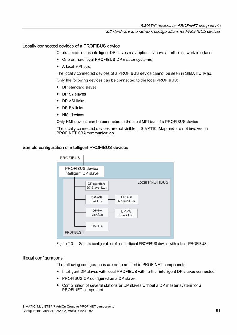
SIMATIC devices as PROFINET components 2.3 Hardware and network configurations for PROFIBUS devices
SIMATIC iMap STEP 7 AddOn Creating PROFINET components Configuration Manual, 03/2008, A5E00716547-02 91
Locally connected devices of a PROFIBUS device Central modules as intelligent DP slaves may optionally have a further network interface: ● One or more local PROFIBUS DP master system(s) ● A local MPI bus. The locally connected devices of a PROFIBUS device cannot be seen in SIMATIC iMap. Only the following devices can be connected to the local PROFIBUS: ● DP standard slaves ● DP S7 slaves ● DP ASI links ● DP PA links ● HMI devices Only HMI devices can be connected to the local MPI bus of a PROFIBUS device. The locally connected devices are not visible in SIMATIC iMap and are not involved in PROFINET CBA communication.
Sample configuration of intelligent PROFIBUS devices
Figure 2-3 Sample configuration of an intelligent PROFIBUS device with a local PROFIBUS
Illegal configurations The following configurations are not permitted in PROFINET components: ● Intelligent DP slaves with local PROFIBUS with further intelligent DP slaves connected. ● PROFIBUS CP configured as a DP slave. ● Combination of several stations or DP slaves without a DP master system for a
PROFINET component

SIMATIC devices as PROFINET components 2.3 Hardware and network configurations for PROFIBUS devices
SIMATIC iMap STEP 7 AddOn Creating PROFINET components 92 Configuration Manual, 03/2008, A5E00716547-02
2.3.3 Intelligent DP slaves as PROFINET components
Hardware configurations You can create PROFINET components from the following programmable distributed peripherals: ● ET 200X with BM 147/CPU ● ET 200S with IM 151/CPU ● CPU 31x-2(DP), C7 6xy DP, CPU 31xC-2DP, CPU 41x-2(DP) (see also chapter "Central
Modules“). Optionally, the SIMATIC 300/400 station may contain the central and distributed I/O devices, see "Configurations for PROFINET components".
Note Direct exchange of data (cross-traffic) between PROFIBUS devices is not supported.
Exchange of data between the DP master and intelligent DP slaves For an intelligent DP slave, the DP master accesses a transfer area in the address space of the CPU, rather than directly accessing the connected inputs/outputs of the intelligent DP slave. To do this, the input and output data for the PROFINET component, i.e. the data of the interface DB, must be transferred from the transfer area and to the transfer area of the intelligent DP slave at the user program runtime. The following copy blocks are needed in the user program to exchange data between the DP master and an intelligent DP slave: PN_IN (FC10) and PN_OUT (FC11).
Figure 2-4 Exchange of data between the interface DB and the I/O area of the intelligent DP slave

SIMATIC devices as PROFINET components 2.3 Hardware and network configurations for PROFIBUS devices
SIMATIC iMap STEP 7 AddOn Creating PROFINET components Configuration Manual, 03/2008, A5E00716547-02 93
Using Non-configured I/O Area in STEP 7 User Programs When creating the user program of a PROFINET component on PROFIBUS, you should ensure that access to the process image (I/O area) is only performed in the area for which I/O modules are configured. Access outside this area is now allowed in STEP 7 user programs and may result in data corruption during the operation of the PROFINET component. This can occur because the area of the process image outside of the configured I/O modules is used by SIMATIC iMap for data communication between the PROFIBUS master and slave.
Copy blocks required in the S7 program of an intelligent DP slave The following off-the-shelf blocks are available in the PROFINET system library:
Block Description FC10 PN_IN - Copies the data from the transfer area of the DP master with proxy
functionality to the input of the interface DB Attribute: CBA_islave_copy_fc and value: in The block PN_IN (FC10) should be called at the start of OB1 to ensure that it is the current data that is transferred to the interface DB.
FC11 PN_OUT – Copies the outputs of the interface DB to the transfer area of the DP master with proxy functionality. Attribute: CBA_islave_copy_fc and value: out The block PN_OUT (FC11) should be called at the end of OB1 to ensure that the data in the transfer area is not overwritten.
DB2 Data block with the attribute: CBA_islave_copy_db and value: true. The DB contains data for the PN_IN and PN_OUT functions and must not be modified.
The numbers of these blocks can be modified as required.
Organizational blocks required The S7 program of an intelligent DP slave must contain the following organizational blocks in order to be able to respond to events: ● OB 82: Diagnostic interrupt, e.g. when the DP master is switched to STOP or RUN. ● OB 86: Rack failure, e.g. when the connection to the DP master is interrupted.

SIMATIC devices as PROFINET components 2.3 Hardware and network configurations for PROFIBUS devices
SIMATIC iMap STEP 7 AddOn Creating PROFINET components 94 Configuration Manual, 03/2008, A5E00716547-02
Example: PROFIBUS device with programmable functionality
Table 2-5 PROFINET component from an ET 200S with IM 151/CPU
Configuration Technological function Device ET 200S with local PROFIBUS
ET 200S
See also Central processing units - Configuration options (Page 77)
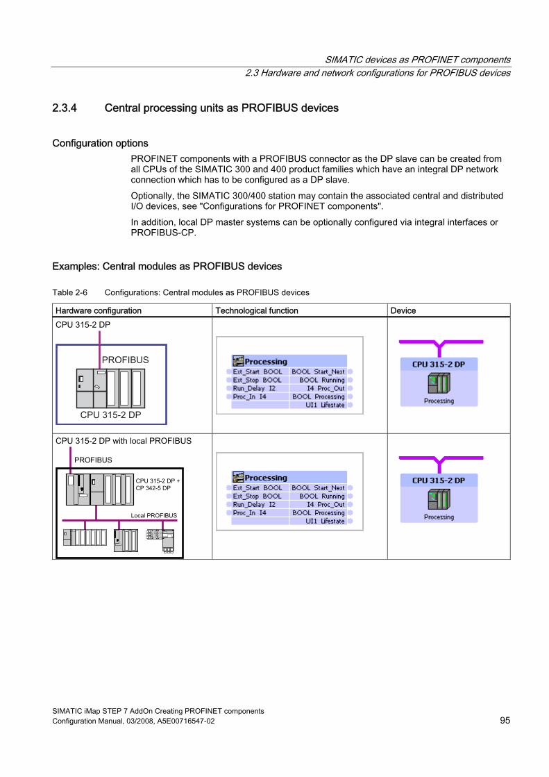
SIMATIC devices as PROFINET components 2.3 Hardware and network configurations for PROFIBUS devices
SIMATIC iMap STEP 7 AddOn Creating PROFINET components Configuration Manual, 03/2008, A5E00716547-02 95
2.3.4 Central processing units as PROFIBUS devices
Configuration options PROFINET components with a PROFIBUS connector as the DP slave can be created from all CPUs of the SIMATIC 300 and 400 product families which have an integral DP network connection which has to be configured as a DP slave. Optionally, the SIMATIC 300/400 station may contain the associated central and distributed I/O devices, see "Configurations for PROFINET components". In addition, local DP master systems can be optionally configured via integral interfaces or PROFIBUS-CP.
Examples: Central modules as PROFIBUS devices
Table 2-6 Configurations: Central modules as PROFIBUS devices
Hardware configuration Technological function Device CPU 315-2 DP
CPU 315-2 DP with local PROFIBUS

SIMATIC devices as PROFINET components 2.3 Hardware and network configurations for PROFIBUS devices
SIMATIC iMap STEP 7 AddOn Creating PROFINET components 96 Configuration Manual, 03/2008, A5E00716547-02
Special features The CP 342-5 is not permitted in the expansion rack. Intelligent DP slaves may not be configured in local DP master systems. When you configure a CPU as a DP intelligent slave, you must set "DP slave" mode in the DP interface properties in HW Config and select the "Programming... " option, if available (see diagram).
Figure 2-5 Configuring a CPU 318-2 as an intelligent DP slave
Please note the following topics: ● Exchange of data between the DP master and intelligent DP slaves - see "Intelligent DP
slaves as PROFINET components" ● Required blocks - see "Intelligent DP slaves as PROFINET components"
See also Central processing units as PROFIBUS devices (Page 95) Distributed peripheral devices as PROFINET components (Page 90)

SIMATIC devices as PROFINET components 2.3 Hardware and network configurations for PROFIBUS devices
SIMATIC iMap STEP 7 AddOn Creating PROFINET components Configuration Manual, 03/2008, A5E00716547-02 97
2.3.5 Configurations for PROFIBUS devices with fixed functionality
Supported devices A PROFIBUS device with fixed functionality may be one of the following devices: ● DP standard slave ● DP S7 slave ● DP ASi link ● Drives
Examples: Configurations of PROFIBUS devices with fixed functionality
DP-ASI Link1...n
DP-ASI Module1...n
Norm /S7 Slave
Figure 2-6 PROFIBUS devices with fixed functionality, hardware configurations
Illegal configurations Combination of several stations or DP slaves without a DP master system for a PROFINET component is not permitted for PROFINET components.
2.3.6 DP slaves with fixed functionality as PROFINET components A DP slave with fixed functionality, such as a compact (ET 200B) or modular (ET 200M) distributed peripheral device, must be configured in a SIMATIC 300 station of the STEP 7 basic project on a DP master in order to create a PROFINET component from it. In this case, the DP master is not part of the PROFINET component.
Devices supported You can create PROFINET components with fixed functionality from the following devices: ● SIMATIC distributed peripherals (standard slaves and S7 slaves) ● DP/ASI link with DP/ASI modules ● Standard slaves which are described by a GSD file ● Drives, e.g. SIMOVERT Micromaster See "Configurations for PROFINET components".

SIMATIC devices as PROFINET components 2.3 Hardware and network configurations for PROFIBUS devices
SIMATIC iMap STEP 7 AddOn Creating PROFINET components 98 Configuration Manual, 03/2008, A5E00716547-02
Special features of DP slaves with fixed functionality The PROFINET component of a compact or modular DP slave has fixed functionality, i.e. there is no separate S7 program running on the device. The interface for the technological function is defined and set on the device. The names of the inputs and outputs of this interface are defined in the interface DB located in the station's block folder. The DP master accesses the distributed inputs/outputs of the DP slave directly, so the interface DB is an image of the process inputs and outputs (see "PROFINET DB for DP slaves with fixed functionality"). The hardware configurations of standard and S7 slaves with fixed functionality that contain programmable modules such as FMs and CPs cannot be used to create PROFINET components. The ET 200L-SC must be configured using GSD files before a PROFINET component can be created from it.
Note Direct exchange of data (cross-traffic) between PROFIBUS devices is not supported.
Use of fail-safe signal modules Hardware configurations with fail-safe signal modules, for example, SM 326F DI/DO or SM 336F AI, in DP slaves with fixed functionality (S7 slaves/standard slaves), are not supported for creating PROFINET components.
Example
Table 2-7 PROFINET components from an ET 200 M
Hardware configuration Technological function Device
See also Central processing units - Configuration options (Page 77)

SIMATIC devices as PROFINET components 2.3 Hardware and network configurations for PROFIBUS devices
SIMATIC iMap STEP 7 AddOn Creating PROFINET components Configuration Manual, 03/2008, A5E00716547-02 99
2.3.7 Special case: DP/DP coupler
Using the DP/DP coupler in SIMATIC iMap The DP/DP coupler enables the data exchange between to PROFIBUS DP masters. One of the masters may also be a non PROFINET-compliant device. It is thus possible to integrate PROFIBUS networks into SIMATIC iMap projects, even without PROFINET-compliant devices. Such networks cannot be shown in SIMATIC iMap, however.
Configuration In STEP 7, the DP/DP coupler is configured as a modular slave in both PROFIBUS networks using a GSD file. The desired length of the input and output data is set during configuration. The output data from one of the slaves is used as the input data for the other slave, and vice versa, Example: PROFIBUS network with a PROFINET-compliant master: 2-byte inputs, 4-byte outputs PROFIBUS network without a PROFINET-compliant master: 4-byte inputs, 2-byte outputs
Note When you configure the DP/DP coupler for the PROFINET-compliant master, make sure that the option "Extended diagnostics enabled" is set in the Properties dialog (see diagram). This means that the diagnostics in SIMATIC iMap can identify whether the master on the other network is available.
Figure 2-7 Configuration of the diagnostics for the DP/DP coupler

SIMATIC devices as PROFINET components 2.3 Hardware and network configurations for PROFIBUS devices
SIMATIC iMap STEP 7 AddOn Creating PROFINET components 100 Configuration Manual, 03/2008, A5E00716547-02
Addressing The DP/DP coupler may have different addresses in the two PROFIBUS networks. The addressing must be carried out both on the device and in SIMATIC iMap.
Note Only use addresses 1 to 124. No other addresses are permitted on PROFIBUS-DP. Changed addresses do not take effect until you switch the power off and on again.
Creating the PROFINET component with STEP 7 The user creates the PROFINET component for the DP/DP coupler in STEP 7 and stores it in the file system in the same way as for a DP slave with fixed functionality. The procedure is described in the section entitled "Creating PROFINET components with STEP 7".
I3I4I5I6
Q1Q2
Q3Q4Q5Q6
I1I2
I1I2I3I4
Q5Q6
Figure 2-8 Example: Interface DB for a DP/DP coupler
Working with the PROFINET component in SIMATIC iMap ● Import the PROFINET component for the DP/DP coupler from the file system to a
SIMATIC iMap library. ● In the net view, link the PROFINET component for the DP/DP coupler to the desired
PROFIBUS. ● In the Properties dialog box for the DP/DP coupler in the net view, enter the PROFIBUS
address set using DIP switches on the device. Note down as a comment which PROFIBUS networks are linked by the DP/DP coupler.
● Interconnect the inputs and outputs in the plant view. ● Generate the project, then download the programs to the associated DP master with
proxy functionality. Download the interconnections to the DP/DP coupler.
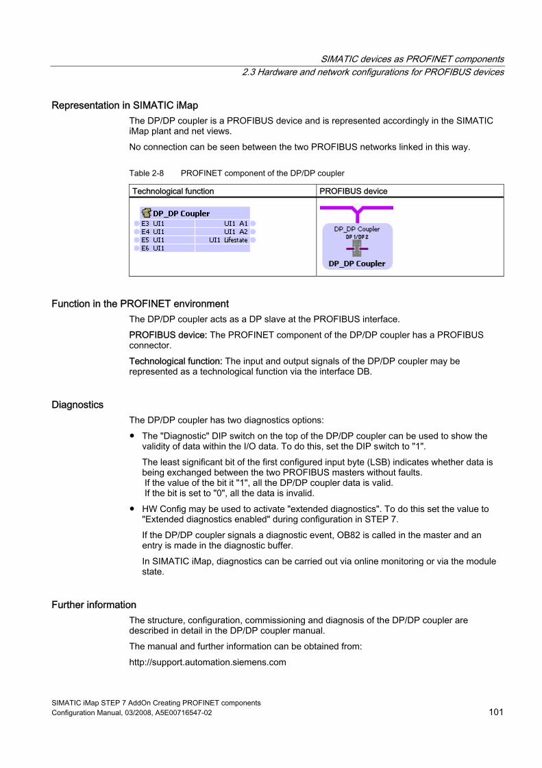
SIMATIC devices as PROFINET components 2.3 Hardware and network configurations for PROFIBUS devices
SIMATIC iMap STEP 7 AddOn Creating PROFINET components Configuration Manual, 03/2008, A5E00716547-02 101
Representation in SIMATIC iMap The DP/DP coupler is a PROFIBUS device and is represented accordingly in the SIMATIC iMap plant and net views. No connection can be seen between the two PROFIBUS networks linked in this way.
Table 2-8 PROFINET component of the DP/DP coupler
Technological function PROFIBUS device
Function in the PROFINET environment The DP/DP coupler acts as a DP slave at the PROFIBUS interface. PROFIBUS device: The PROFINET component of the DP/DP coupler has a PROFIBUS connector. Technological function: The input and output signals of the DP/DP coupler may be represented as a technological function via the interface DB.
Diagnostics The DP/DP coupler has two diagnostics options: ● The "Diagnostic" DIP switch on the top of the DP/DP coupler can be used to show the
validity of data within the I/O data. To do this, set the DIP switch to "1". The least significant bit of the first configured input byte (LSB) indicates whether data is being exchanged between the two PROFIBUS masters without faults. If the value of the bit it "1", all the DP/DP coupler data is valid. If the bit is set to "0", all the data is invalid.
● HW Config may be used to activate "extended diagnostics". To do this set the value to "Extended diagnostics enabled" during configuration in STEP 7. If the DP/DP coupler signals a diagnostic event, OB82 is called in the master and an entry is made in the diagnostic buffer. In SIMATIC iMap, diagnostics can be carried out via online monitoring or via the module state.
Further information The structure, configuration, commissioning and diagnosis of the DP/DP coupler are described in detail in the DP/DP coupler manual. The manual and further information can be obtained from: http://support.automation.siemens.com

SIMATIC devices as PROFINET components 2.4 HMI devices in PROFINET components
SIMATIC iMap STEP 7 AddOn Creating PROFINET components 102 Configuration Manual, 03/2008, A5E00716547-02
2.4 HMI devices in PROFINET components When you create a PROFINET component, you can set up an HMI device (e.g. operator panel or multi-panel) as part of the PROFINET component. This chapter describes the points to note when integrating HMI devices into a PROFINET component.
Network configurations with integrated HMI devices You can integrate HMI devices into a PROFINET component by incorporating it into the internal networking of the station. You have the following possibilities: ● an HMI device on the local MPI bus ● one or more HMI devices:
– on the Industrial Ethernet (only HMI devices which are configured with WinCC Flexible)
– on the local PROFIBUS – within a PC station
The local bus systems of the PROFINET component, and the devices that they network, cannot be seen in SIMATIC iMap. Consequently, integrated HMI devices are not displayed as such in SIMATIC iMap.
Rules for integrating HMI devices ● PROFINET components may only contain HMI devices which are configured, generated
and downloaded with ProTool/Pro CS or WinCC Flexible. ● For a complete C7 6xy device, an HMI device may only be integrated via MPI.
Configuration on the PROFIBUS or Industrial Ethernet is not possible.
Example: integrated HMI devices on the Industrial Ethernet
Ethernet
PROFINET device
HMI1...n
Figure 2-9 Integrated HMI devices on the Industrial Ethernet

SIMATIC devices as PROFINET components 2.4 HMI devices in PROFINET components
SIMATIC iMap STEP 7 AddOn Creating PROFINET components Configuration Manual, 03/2008, A5E00716547-02 103
Example: integrated HMI devices on the local PROFIBUS of a PROFINET device
Ethernet
Local PROFIBUS
PROFINET device
HMI1...n
ISlave1...n
Norm/S7slave1...n
Figure 2-10 HMI devices on the local PROFIBUS of a PROFINET device
Example: integrated HMI devices on the local PROFIBUS of a PROFIBUS device
PROFIBUS
Local PROFIBUS
PROFIBUS deviceintelligent DP slave
HMI1...n
Norm/S7slave1...n
Figure 2-11 HMI devices on the local PROFIBUS of a PROFIBUS device

SIMATIC devices as PROFINET components 2.4 HMI devices in PROFINET components
SIMATIC iMap STEP 7 AddOn Creating PROFINET components 104 Configuration Manual, 03/2008, A5E00716547-02
Processing in SIMATIC iMap Integrated HMI devices as parts of a PROFINET component cannot be seen in SIMATIC iMap. The devices must be configured and the program downloaded to the target device using WinCC Flexible or ProTool/Pro CS.
Requirement A direct connection between the PC and the HMI device is required in order to download to the HMI device. Set the access point of the S7ONLINE (STEP7) application to the corresponding interface parameter settings in the PG/PC interface: ● Industrial Ethernet ● MPI ● PROFIBUS ● Point-to-point connection.
Configuration and downloading The following steps are required: 1. Generate the project in SIMATIC iMap using the Generate >menu command so that the
generation status of the device is "Generated". 2. Select the device from the net view and select Special > HMI from the pop-up menu. This
calls the associated project in WinCC Flexible or ProTool/Pro CS for the HMI device. 3. In WinCC Flexible or ProTool/Pro CS: Download the data to the HMI device.
CAUTION
When the SIMATIC iMap project is regenerated, any changes to the HMI device configuration will be lost. When you change the configuration, we therefore recommend that you recreate the entire PROFINET component and replace it in the SIMATIC iMap project.

SIMATIC iMap STEP 7 AddOn Creating PROFINET components Configuration Manual, 03/2008, A5E00716547-02 105
Special PROFINET components 33.1 Multi-function components
3.1.1 Properties of the multi-function components
Multi-function component The technological interface of a multi-function component is divided in several part functions. The part functions form the technological function of the component type.
Advantages The division of large technological interfaces with several hundred connectors over several part functions offers the following advantages: ● Clearer display in SIMATIC iMap ● Better structuring possibilities of the plant in SIMATIC iMap on account of the flexible
arrangement and, if necessary, division of the part functions over several charts.
Structure of a multi-function component Compared to PROFINET components with just one function, the PROFINET interface of a multi-function component is divided into several part functions. Each instance includes all part functions that are shown and handled individually in SIMATIC iMap. The user program including the hardware configuration data however continues to form one unit. Therefore, the device-specific actions, like for example generating, as well as all online and diagnostics commands always refer to the complete instance. Multifunction components must be programmable, i.e. thes can only be created based on the data of controllers or intelligent DP slaves. Multi-function components can be either standard or Singleton components.

Special PROFINET components 3.1 Multi-function components
SIMATIC iMap STEP 7 AddOn Creating PROFINET components 106 Configuration Manual, 03/2008, A5E00716547-02
Number of functions per device The maximum permitted number of part functions of a multi-function component depends on the component type: ● With standard components with programmable functionality, up to 7 part functions are
permitted. ● With standard components with fixed functionality, a maximum of 1 function is permitted. ● With singleton components, the maximum permitted number of part functions is variable,
depending on the device type. In all cases, the entire PROFINET interface may not exceed the performance parameters of the device with reference to the number of connectors and the maximum data length. The maximum permitted number of part functions is a technical datum of the PROFINET CBA-compliant devices and is displayed in SIMATIC iMap for the following actions: ● Check utilization, device parameter "Number of functions on master and slaves" ● Online device analysis, parameter "Number of operable functions"
Note Multi-function components with proxy functionality For PROFINET devices with proxy functionality, this incorporates the functions or part functions of the coupled PROFIBUS devices. Example: The multifunction component of a CPU 319-3 PN/DP with proxy functionality has 4 functions. A maximum of 30 part functions are allowed for this device. A maximum of 26 PROFIBUS devices can therefore each be coupled to a function. The number of PROFIBUS devices which can be coupled to it is reduced accordingly if one or more of these instances also contain several part functions.
See also Creating multi-function components (Page 107)

Special PROFINET components 3.1 Multi-function components
SIMATIC iMap STEP 7 AddOn Creating PROFINET components Configuration Manual, 03/2008, A5E00716547-02 107
3.1.2 Creating multi-function components
Requirements The STEP 7 basic project has been created and the hardware configuration of the station saved.
How to create a multi-function component: 1. Open the project in SIMATIC Manager, if you have not already done so. 2. Highlight the station and select the Create PROFINET interface menu command. 3. In the dialog "PROFINET interface new/open" select the device in the left box (project
view). 4. With the element "Add new function" add the desired number of functions. 5. Give the names to functions. To do this, select Rename function from the pop-up menu. 6. Assign a PROFINET interface DB to each function and optionally one or more HMI
interface DBs. 7. Edit and save the interface DBs. 8. Close the PROFINET interface editor. 9. Highlight the station and select the Create PROFINET component menu command. 10. Perform the following steps in the "General" tab:
– Select "Create component from the station". – Enter the name, the device name, the version number (optional) and a comment, if
necessary. – In the "Identification" box, decide whether an existing identification should be retained
or whether a new identification should be assigned.. 11. In the "Component Type" tab select the required tab: Standard or singleton component. 12. In the "Functions" tab the functions and the associated blocks are displayed. 13. On the "Storage area" tab, define the storage area of the component: target library and/or
file system. 14. Perform the following steps in the "Additional Properties" tab:
– Define the paths for the icon files. – Define the path or address of the documentation link (optional).
15. Click on OK to confirm your input. Result: The multi-function component is created in the specified storage area.

Special PROFINET components 3.1 Multi-function components
SIMATIC iMap STEP 7 AddOn Creating PROFINET components 108 Configuration Manual, 03/2008, A5E00716547-02
Example: Structure of a PROFINET component with three functions The assignment between the device, functions and interface blocks can be seen in the dialog "PROFINET Interface - New/Open".
Further procedure ● If you have specified a target library as the storage area, you can insert the multi-function
component immediately into a SIMATIC iMap project. ● If you have specified a path in the file system as the storage area, you will first have to
import the multi-function component into a library in SIMATIC iMap.
See also Properties of the multi-function components (Page 105)

Special PROFINET components 3.2 Singleton components
SIMATIC iMap STEP 7 AddOn Creating PROFINET components Configuration Manual, 03/2008, A5E00716547-02 109
3.2 Singleton components
3.2.1 Properties of singleton components
What are singleton components? Singleton components are PROFINET components for which the device-specific data is stored and handled separately. The device-specific configuration information and program data is located in the STEP 7 basic project for the PROFINET component, rather than in the common shadow project.
Advantages in use The use of singleton components has the following advantages: ● Because the device-specific configuration and program data are stored separately,
Singleton components in SIMATIC iMap are excluded from certain time-consuming functions such as generation or program downloads, and thus do not affect the processing time of the overall project.
● Singleton components may have default names and addresses. Thus, these properties do not have to be configured for instances of Singleton components in SIMATIC iMap.
● Special hardware configurations with SIMATIC device that were not supported in PROFINET components in the past can now be incorporated into PROFINET communication as Singleton components.
● Singleton multi-function components may contain more than 7 part functions. The maximum number of part functions depends on the device type.

Special PROFINET components 3.2 Singleton components
SIMATIC iMap STEP 7 AddOn Creating PROFINET components 110 Configuration Manual, 03/2008, A5E00716547-02
Separate storage of the singleton components Singleton components do not have a STEP 7 component project but rather only the STEP 7 basic project (singleton project). For this reason, the following actions in SIMATIC iMap are performed directly in the Singleton project and not through the shadow project: Generation, program downloads and revision of the singleton component. This concept is illustrated in the figure below.
Figure 3-1 Actions in the basic project of the singleton component
Rule Singleton components can only be created for PROFINET devices without proxy functionality. Thus, singleton components have only one bus connection on the Industrial Ethernet.

Special PROFINET components 3.2 Singleton components
SIMATIC iMap STEP 7 AddOn Creating PROFINET components Configuration Manual, 03/2008, A5E00716547-02 111
Special hardware configurations The Singleton concept allows special hardware configurations with SIMATIC devices to be incorporated into the PROFINET communication, such as: ● Integration of process diagnostics ● Configurations with function modules (FM) ● Configurations with several central modules (multi-computing) ● Integration of connections to other stations via ISO protocol
3.2.2 Creating singleton components
Requirements The requirements for the standard PROFINET components must be given: The STEP 7 project with hardware configuration, the PROFINET interface DB and the S7 program must be created. The Ethernet interface must also be configured with the correct IP address and subnet mask.
Note For singleton components that can only have one instance in the SIMATIC iMap project it is not possible to change the names and address(es) of the instance.
How to create singleton components 1. Open the project in SIMATIC Manager, if you have not already done so. 2. Highlight the station and select the Create PROFINET component menu command. 3. On the "General" tab:
– Select "Create component from the station". – Enter the name, the version number (optional) and a comment, if necessary. – In the "Identification" box, decide whether an existing identification should be retained
or whether a new identification should be assigned.. 4. On the "Component type" tab, check the "Singleton" check box. 5. On the "Storage area" tab, define the storage area of the component: target library and/or
file system. 6. On the "Additional Properties" tab:
– Define the paths for the icon files. – Define the path or address of the documentation link (optional).
7. Click on OK to confirm your input. Result: The singleton component is created in the specified storage area.

Special PROFINET components 3.2 Singleton components
SIMATIC iMap STEP 7 AddOn Creating PROFINET components 112 Configuration Manual, 03/2008, A5E00716547-02
NOTICE Singleton components have no STEP 7 component project. The following actions are carried out directly in the singleton project (STEP 7 basic project for the singleton component): • Downloading programs to the target system • Re-editing singleton components • Looking up device-specific diagnostics We recommend that you store the STEP 7 basic project in the STEP 7 folder provided (step7\s7proj) so that it can be quickly traced in SIMATIC Manager.
Further procedure ● If you have specified a target library as the storage area, you can insert the singleton
component immediately into a SIMATIC iMap project. ● If you have specified a path in the file system as the storage area, you will first have to
import the singleton component into a library in SIMATIC iMap.

SIMATIC iMap STEP 7 AddOn Creating PROFINET components Configuration Manual, 03/2008, A5E00716547-02 113
Appendix AA.1 Controls of the PROFINET interface editor
A.1.1 Menu commands
"File" menu
Command Description New Opens the "New/open PROFINET interface" dialog box for
creating a new block (interface DB) Open Opens the "New/open PROFINET interface" dialog box for
opening an existing block Close Closes the current block Save Saves the current block Properties Displays the properties of the active block Check CBA Consistency of All Active PN Blocks
Checks the consistency of the PROFINET interface DB. Comparison with the performance parameters of the device
Check STEP 7 Block Consistency
Checks the consistency of the used FB and the instance DB.
Print Prints the current block Page View Displays a whole page Printer Setup Changes the printer and the printing options Recently Opened Interfaces Opens one of the recently opened interface blocks Exit Exits the interface editor

Appendix A.1 Controls of the PROFINET interface editor
SIMATIC iMap STEP 7 AddOn Creating PROFINET components 114 Configuration Manual, 03/2008, A5E00716547-02
"Edit" menu
Command Description New declaration line Inserts a new declaration line with default values Cut Deletes the selection and transfers it to the clipboard Copy Copies the selection and transfers it to the clipboard Paste Inserts the clipboard contents Delete Deletes the current declaration line Object properties Displays the properties of the selected object. Show columns Opens the dialog box for changing the number and sequence of
the columns displayed in the variable detail view
"View" menu
Command Description Toolbar Shows or hides the toolbar Status bar Shows or hides the status bar
"Window" menu
Command Description Cascade Cascades all open windows one behind the other Horizontally Tiles all open windows from top to bottom Vertically Tiles all open windows from left to right Arrange Icons Arranges the icons in the bottom part of the window Active Window Activates the selected window
"Help" menu
Command Description Help Topics Calls up help about the PROFINET interface editor About Displays information about the program, version number and
copyright

Appendix A.1 Controls of the PROFINET interface editor
SIMATIC iMap STEP 7 AddOn Creating PROFINET components Configuration Manual, 03/2008, A5E00716547-02 115
A.1.2 Icons in the PROFINET interface editor In addition to the icons known from STEP 7, the PROFINET interface editor features the following icons for object types and actions:
Table A-1 Icons for object types:
Icon Meaning
Function
Block folder, closed
Block folder, open
Declaration section for inputs (PN_Input).
Declaration section for outputs (PN_Output).
Declaration section for S7 variables (S7_Variable) and Declaration section for unassigned connectors (Unassigned)
DP_MasterInputSlot or DP_MasterOutputSlot
Elementary data type (e.g. Bool, Byte, Word, Int).
Array with elements of an elementary data type.
Structured data type (STRUCT).
Empty element (always the last element in a folder).
Table A-2 Icons for actions
Icon Meaning
Add function
Add block
Check CBA Consistency of All Active PN Blocks
Check STEP 7 Block Consistency

Appendix A.1 Controls of the PROFINET interface editor
SIMATIC iMap STEP 7 AddOn Creating PROFINET components 116 Configuration Manual, 03/2008, A5E00716547-02
A.1.3 Keyboard commands in the variable overview
Functions and keys in the variable overview
Function Keys One object up. Up One object down. Down Display the next hierarchical level Right or + Close a hierarchical level Left or - Show All Levels x (multiplication key on the keypad) Go to topmost object in the directory tree Pos1 Go to bottom object in the directory tree End Go to higher level object Home Move up one page Page Up Move down one page Page Down

Appendix A.1 Controls of the PROFINET interface editor
SIMATIC iMap STEP 7 AddOn Creating PROFINET components Configuration Manual, 03/2008, A5E00716547-02 117
A.1.4 Keyboard commands in the variable detail view
Functions and keys in the variable detail view
Function Keys Select all elements. Ctrl + A Highlight the entire text in a field F3 Move one field to the right Right Move one field to the left Left Move one field up Up Move one field down Down To the first column Ctrl + Left To the last column Ctrl + Right Move up one page Page Up Move down one page Page Down Highlight several rows Shift + Up /
Shift + Down Highlight all rows up to the start. Shift + Ctrl + Up Highlight all rows down to the end Shift + Ctrl + Down To next field of the table Tab To previous field of the table Shift + Tab Go to higher level object Home Reduce width of column F7 Increase width of column F8 Confirm input and move to next row Enter Run a defined standard operation for the highlighted object (e.g. Call object properties)
Shift + Enter
Activate / deactivate an option (check a check box).
Space bar
Insert a variable CTRL + V Delete a variable. Delete Show columns. F11

Appendix A.2 Naming conventions for PROFINET components
SIMATIC iMap STEP 7 AddOn Creating PROFINET components 118 Configuration Manual, 03/2008, A5E00716547-02
A.2 Naming conventions for PROFINET components
Naming conventions for PROFINET components Naming conventions to be observed:
File and folder names A file or folder name may not contain any of the following characters: \ / : ?" * < > |
Names of PROFINET components, technological functions and devices ● The names may not be blank. ● Space characters are not allowed as first and last characters of the name. ● Name length: The names may not exceed a length of 24 characters. ● All printable characters from ISO 8859-1 (ISO Latin 1) are allowed except the following
characters:
Characters English Unicode Name ! EXCLAMATION MARK " QUOTATION MARK & AMPERSAND * ASTERISK + PLUS SIGN , COMMA . FULL STOP (= PERIOD) / SOLIDUS (= SLASH) : COLON ; SEMICOLON < LESS-THAN SIGN = EQUALS SIGN > GREATER-THAN SIGN ? QUESTION MARK [ LEFT SQUARE BRACKET(= OPENING SQUARE BRACKET) \ REVERSE SOLIDUS (= BACKSLASH) ] RIGHT SQUARE BRACKET (= CLOSING SQUARE BRACKET) ^ CIRCUMFLEX ACCENT ` GRAVE ACCENT | VERTICAL LINE (= VERTICAL BAR) ´ ACUTE ACCENT
Appendix A.2 Naming conventions for PROFINET components
SIMATIC iMap STEP 7 AddOn Creating PROFINET components Configuration Manual, 03/2008, A5E00716547-02 119
Note The € character is not allowed because it is not included in the ISO Latin 1 set.
Connector names ● Characters allowed in connector names (to ISO 10646-1):
Letters A to Z and a to z, digits 0 to 9, and the underscore character "_". ● The first characters of a connector name must be a letter (not underscore or a number.)
Connectors with names beginning with an underscore cannot be assigned a PROFINET CBA characteristic, such as "Connectable".
● The length of a connector name may not exceed 24 characters.

Appendix A.3 Data types of connectors
SIMATIC iMap STEP 7 AddOn Creating PROFINET components 120 Configuration Manual, 03/2008, A5E00716547-02
A.3 Data types of connectors
Data types, data lengths and ranges of values for connections A PROFINET data type conforming to Microsoft© OLE 2.0 is assigned to every S7 data type. The following table show the permissible S7 data types for PROFINET CBA and the corresponding PROFINET data types as well as the data lengths and value ranges.
Table A-3 Data types for PROFINET CBA
PROFINET data type
S7 data type Data length in bytes
Range of values
BOOL BOOL 2 TRUE / FALSE I1 CHAR 1 -128 to +127 UI1 BYTE 1 0 to 255 R4 REAL 4 -3.402823 E+38 to -1.175495 E-38
0 1.175495 E-38 to +3.402823 E+38
I2 INT 2 -32.768 to +32.767 UI2 WORD 2 0 to 65.535 I4 DINT 4 - 2.147.483.648 to +2.147.483.647 UI4 DWORD 4 0 to 4.294.967.295 DATE DT (DATE_AND_TIME) 8 01.01.1900 00:00:00 to 31.12.9999
00:00:00*) BSTR STRING 4 + 2 * number of
characters Character string
ARRAY ARRAY Number * data type length
Multidimensional, from the data types listed here**)
STRUCT STRUCT or UDT Sum of the data type lengths
Combined from the data types listed here**)
*) There may be restrictions in the range of values, depending on the type of device e.g. for SIMATIC devices this would be: 01.01.1990 00:00:00 to 31.12.2089 23:59:59. **) Maximum of 6 dimensions. The maximum length depends on the amount of memory in the device ***) Maximum 8-level structures. The maximum length depends on the amount of memory in the device.
Data types supported in PROFINET runtime version V2.0.0.0 or later The following data types are supported by PROFINET devices in runtime version V2.0.0.0 or later: ● Data type STRUCT with all simple data types, including STRING ● Data type ARRAY with the data types BOOL, REAL, DATE_AND_TIME, STRING ● User-defined data types (UDT) with all simple data types, including STRING Earlier Runtime versions do not support these data types.

Appendix A.3 Data types of connectors
SIMATIC iMap STEP 7 AddOn Creating PROFINET components Configuration Manual, 03/2008, A5E00716547-02 121
Data types supported in PROFINET runtime Version V2.3.0.0 or higher The following data types are supported by PROFINET devices in runtime version V2.3.0.0 or higher: ● STRUCT/UDT data type with all the data types listed above ● ARRAY data type, multidimensional, with all the data types listed above Earlier Runtime versions do not support these data types.
See also S7 data and parameter types
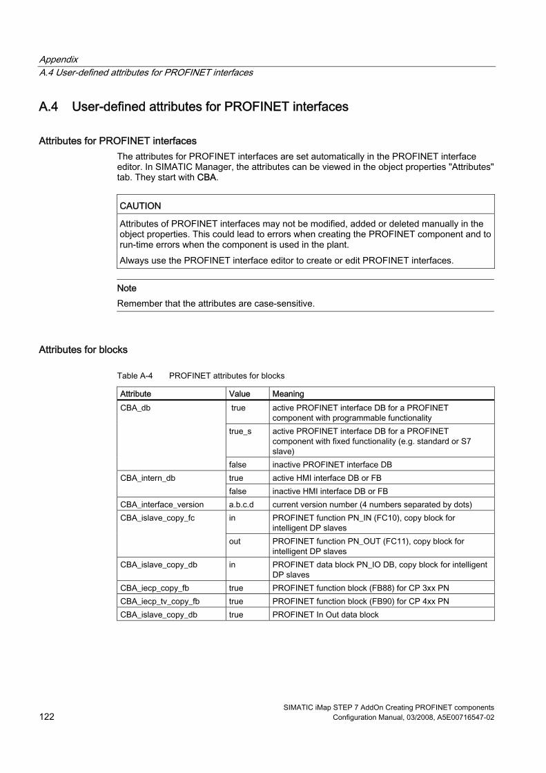
Appendix A.4 User-defined attributes for PROFINET interfaces
SIMATIC iMap STEP 7 AddOn Creating PROFINET components 122 Configuration Manual, 03/2008, A5E00716547-02
A.4 User-defined attributes for PROFINET interfaces
Attributes for PROFINET interfaces The attributes for PROFINET interfaces are set automatically in the PROFINET interface editor. In SIMATIC Manager, the attributes can be viewed in the object properties "Attributes" tab. They start with CBA.
CAUTION Attributes of PROFINET interfaces may not be modified, added or deleted manually in the object properties. This could lead to errors when creating the PROFINET component and to run-time errors when the component is used in the plant. Always use the PROFINET interface editor to create or edit PROFINET interfaces.
Note
Remember that the attributes are case-sensitive.
Attributes for blocks
Table A-4 PROFINET attributes for blocks
Attribute Value Meaning true active PROFINET interface DB for a PROFINET
component with programmable functionality true_s active PROFINET interface DB for a PROFINET
component with fixed functionality (e.g. standard or S7 slave)
CBA_db
false inactive PROFINET interface DB true active HMI interface DB or FB CBA_intern_db false inactive HMI interface DB or FB
CBA_interface_version a.b.c.d current version number (4 numbers separated by dots) in PROFINET function PN_IN (FC10), copy block for
intelligent DP slaves CBA_islave_copy_fc
out PROFINET function PN_OUT (FC11), copy block for intelligent DP slaves
CBA_islave_copy_db in PROFINET data block PN_IO DB, copy block for intelligent DP slaves
CBA_iecp_copy_fb true PROFINET function block (FB88) for CP 3xx PN CBA_iecp_tv_copy_fb true PROFINET function block (FB90) for CP 4xx PN CBA_islave_copy_db true PROFINET In Out data block

Appendix A.5 The "lifestate" connector in SIMATIC devices
SIMATIC iMap STEP 7 AddOn Creating PROFINET components Configuration Manual, 03/2008, A5E00716547-02 123
A.5 The "lifestate" connector in SIMATIC devices
The "Lifestate" connection in SIMATIC devices The technological functions of the PROFINET components that were created in STEP 7 receive an additional output of the type UI1, called "Lifestate". The output signals the current operating state of the CPU within the PROFINET component. The "Lifestate" output can be interconnected in SIMATIC iMap and evaluated by the user program of a PROFINET communication partner.
Lifestate values The lifestate output can return the following values, which describe the current state of the device:
Value State Meaning in PROFINET devices Meaning in PROFIBUS devices 0x00 Nonexistent The device is not powered and is thus unable to communicate. This operating
state cannot be transferred via the interconnection since no communication is possible. It is only listed for the sake of completeness. This value is also the default substitute value.
0x01 Initializing The device is initializing, e.g. after a power off or reset. 0x02 Ready The device is ready for use, but the
component is not active. The device outputs are in the safe state. This state corresponds to the STOP operating state of a CPU/DP master, for example.
The PROFIBUS is in the "CLEAR" state (the DP master is in the STOP operating state. Or Communications is interrupted
0x03 Operating The device is operating normally. This state corresponds to the RUN operating state of a CPU, for example.
The PROFIBUS is in the "OPERATE" state (the DP master is in the RUN operating state and the DP slave is in the RUN or STOP operating state.
0x04 Defect There is an error in the device that cannot be rectified without further intervention. Typical examples include hardware or firmware errors. The device can only be restarted by switching the power off and on again. Only limited communication is possible with the device, depending on the type of error.
The value is 1 byte long.

Appendix A.5 The "lifestate" connector in SIMATIC devices
SIMATIC iMap STEP 7 AddOn Creating PROFINET components 124 Configuration Manual, 03/2008, A5E00716547-02
Lifestate values at the interconnected inputs
NOTICE The values supplied at the output are not always applied at inputs that are interconnected to lifestate outputs. The value 0x03 (Operating) is transferred unchanged. The value 0x02 (Ready) is only transferred unchanged by PROFINET devices. All the other values are replaced by the substitution value respectively configured.
The following tables list the sent and received values for PROFINET and PROFIBUS devices.
Table A-5 Lifestate outputs of PROFINET devices
State Sent value Sent "Quality" characteristic
Received value Value applied at input
Nonexistent 0x00 Substitution value Initializing 0x01 Substitution value Ready 0x02 Bad 0x02 Substitution value Operating 0x03 Good 0x03 0x03 Defect 0x04 Substitution value
Table A-6 Lifestate outputs of PROFIBUS devices
State Sent value Sent "Quality" characteristic
Received value Value applied at input
Nonexistent 0x00 Substitution value Initializing 0x01 Substitution value Ready 0x02 Substitution value Operating 0x03 Good 0x03 0x03 Defect 0x04 Substitution value

SIMATIC iMap STEP 7 AddOn Creating PROFINET components Configuration Manual, 03/2008, A5E00716547-02 125
Abbreviations BAbbreviations
Abbreviation Explanation CBA Ccomponent Based Automation COM Component Object Model DCOM Distributed Ccomponent Object Model HMI Human Machine Interface IE Industrial Ethernet IRT Isochronous Realtme MES Manufacturing Engineering System MAC Medium Access Control OLE Object Linking and Embedding OPC OLE for Process Control PB PROFIBUS PCD PROFINET Ccomponent Description UDT User-defined Data Type PN PROFINet QoS Quality of Service TIA Totally Integrated Automation UNC Uniform Naming Convention URL Uniform Resource Locator XML EXtended Markup Language

Abbreviations
SIMATIC iMap STEP 7 AddOn Creating PROFINET components 126 Configuration Manual, 03/2008, A5E00716547-02

SIMATIC iMap STEP 7 AddOn Creating PROFINET components Configuration Manual, 03/2008, A5E00716547-02 127
Technical Support SIMATIC CC.1 SIMATIC Technical Support
SIMATIC Technical Support You can contact Technical Support for all A&D products: ● via the Internet using the Support Request:
http://www.siemens.com/automation/support-request ● E-mail: [email protected] ● Phone: +49 (0) 180 5050 222 ● Fax: +49 (0) 180 5050 223 Further information about our technical support is available in the Internet at www.siemens.com/automation/service
Service & Support on the Internet In addition to our documentation, we offer a comprehensive knowledge base online on the Internet at: http://www.siemens.com/automation/service&support There you will find: ● The latest product information, FAQs, downloads, tips and tricks. ● Our newsletter, providing you with the latest information about your products. ● A Knowledge Manager to find the right documents for you. ● Our bulletin board, where users and specialists share their knowledge worldwide. ● your local contact partner for Automation & Drives in our Partner Database ● Information about field service, repairs, spare parts and lots more under "Services."

Technical Support SIMATIC C.1 SIMATIC Technical Support
SIMATIC iMap STEP 7 AddOn Creating PROFINET components 128 Configuration Manual, 03/2008, A5E00716547-02
Additional Support Please contact your local Siemens representative and offices if you have any questions about the products described in this manual and do not find the right answers. Find your contact partner at: http://www.siemens.com/automation/partner A signpost to the documentation of the various SIMATIC products and systems is available at: http://www.siemens.de/simatic-tech-doku-portal
Training center SIEMENS offers a range of courses to help you to get started with your S7-300 Automation System. Please contact your local Training Center, or the Central Training Center in Nuremberg, D -90327 Germany. Phone: +49 (911) 895-3200 http://www.sitrain.com
See also Preface Creating PROFINET components (Page Fehler! Textmarke nicht definiert.)

SIMATIC iMap STEP 7 AddOn Creating PROFINET components Configuration Manual, 03/2008, A5E00716547-02 129
Glossary
Basic project Project folder in the manufacturer-specific configuration tool, which is used to create a PROFINET component. Example: STEP 7 basic project
Chart In SIMATIC iMap: Folder which contains the technological functions and their interconnections. The chart is used to structure the plant. We distinguish between the plant chart and nested charts.
Chart interface The chart interface of a nested chart contains the IO of its technological functions which can be interconnected beyond the chart boundaries.
Chart view In SIMATIC iMap: representation of the chart hierarchy of the plant, including all function instances and charts.
Chart, nested In SIMATIC iMap: a nested chart may be located on any lower level in the plant view's hierarchy. It may contain technological functions and further nested charts.
Component Based Automation → PROFINET CBA
Component project Contains manufacturer-specific project data of the PROFINET component, for example, as STEP 7 project.
Continuation connector Graphical representation of the end point of an interconnection. SIMATIC iMap represents interconnections in the form of lines or continuation connectors.

Glossary
SIMATIC iMap STEP 7 AddOn Creating PROFINET components 130 Configuration Manual, 03/2008, A5E00716547-02
Device Within the context of PROFINET, "device" is the generic term for: ● Automation systems (e.g. PLC, PC) ● Field devices (for example, PLC, PC, hydraulic devices, pneumatic devices), and ● active network components (e.g. switches, gateways, routers) In PROFINET CBA: part of the PROFINET component that contains the hardware-specific data for that component. In SIMATIC iMap, a device is considered the software representation of the physical device for which the PROFINET component was created. It is represented in the network view of SIMATIC iMap as an object with one or several bus connections. The main feature of a device is that it is integrated into the PROFINET communication via Industrial Ethernet or PROFIBUS. We differentiate between the following types of devices based on their bus connectors: ● PROFINET devices ● PROFIBUS devices
Device instance → Instance
fixed functionality → Functionality, fixed
Function instance → Instance
Functionality, fixed A PROFINET component with fixed functionality does not contain an inherent user program.
Functionality, programmable A PROFINET component with programmable functionality contains an integrated user program.
Instance The instance of a PROFINET component represents the use of a component type in a SIMATIC iMap project. The instance comprises the function and device instances.

Glossary
SIMATIC iMap STEP 7 AddOn Creating PROFINET components Configuration Manual, 03/2008, A5E00716547-02 131
Interconnection General: Logic link of data between two objects. In SIMATIC iMap: Logical link between two technological functions. An output is always connected to an input of the same data type. SIMATIC iMap represents interconnections in the form of lines or continuation connectors.
Interconnections with local communication partners Interconnections with local communication partners are: Interconnections between two PROFIBUS devices on the same PROFIBUS Interconnections between a PROFIBUS device and the associated PROFINET device with proxy functionality
Interconnections with remote communication partners Interconnections with remote communication partners are routed across Industrial Ethernet.
Interface DB Component Based Automation Data block in STEP 7 which describes the IO of the technological function.
Library In SIMATIC iMap: Folder which contains reusable PROFINET component types. There are two types: the project library, and the shared library.
MAC address Each PROFINET device is assigned a worldwide unique device identifier in the factory. This device ID has a length of six byte and represents the MAC address (MAC = Medium Access Control.) The MAC address consists of: ● 3 bytes for the manufacturer ID, and ● 3 bytes for the device ID (consecutive number). The MAC address is usually printed on the front panel of the device. For example: 08-00-06-6B-80-C0
Multi-function component The technological interface of a multi-function component is divided in several part functions. The part functions form the technological function of the component type.
nested chart → Chart, nested

Glossary
SIMATIC iMap STEP 7 AddOn Creating PROFINET components 132 Configuration Manual, 03/2008, A5E00716547-02
Network view Representation of devices and networks (Ethernet, PROFIBUS) in SIMATIC iMap.
PCD → PROFINET Component Description
Plant chart In SIMATIC iMap: the plant chart represents the highest layer in the hierarchy of the plant view. It contains all technological functions, the nested charts and their interconnections
Plant view Representation of technological functions of the automation system and their interconnections in SIMATIC iMap. The plant view shows one chart
PROFIBUS device In PROFINET CBA: A PROFIBUS device has just one PROFIBUS connector and is always a slave. It can not directly participate in PROFINET communication, and must be integrated using a PROFIBUS device with proxy functionality.
PROFINET PROFINET is the open Industrial Ethernet standard for automation. The PROFINET standard defines a manufacturer-independent communication and engineering model. PROFINET is implemented within the TIA framework based on two automation concepts: ● PROFINET IO - for communication between a PROFINET IO controller and PROFINET
IO devices. ● PROFINET CBA.(Component Based Automation) - for machine-to-machine
communication (between PLCs and intelligent field devices.)
PROFINET CBA PROFINET CBA represents an automation concept in modular systems engineering, based on ready-to-use components. PROFINET CBA incorporates the communication between the PLC and intelligent field devices (machine-to-machine communication) at unit level.
PROFINET component Software representation of a technological module with defined functionality. An automation system consists of several PROFINET components. A PROFINET component always comprises one or several technological functions and the corresponding device.

Glossary
SIMATIC iMap STEP 7 AddOn Creating PROFINET components Configuration Manual, 03/2008, A5E00716547-02 133
PROFINET Component Description The PROFINET component description refers to components you have generated in the engineering system (for example STEP 7.) The PCD is an XML file that you can import into SIMATIC iMap so that you can configure the PROFINET CBA communication.
PROFINET controllers Controller which may be a PROFINET component (CBA) and also support PROFINET IO.
PROFINET device A PROFINET device always has at least one Industrial Ethernet port. A PROFINET device may feature one or several PROFIBUS connectors, and thus act as a master with proxy functionality.
PROFINET device with proxy functionality The PROFINET device with proxy functionality is a proxy for PROFIBUS devices on Industrial Ethernet. The proxy functionality allows a PROFIBUS device to communicate with all participants in the PROFINET communication, as well as with its DP master. A device featuring only a local (internal) PROFBUS represents a DP master to the local DP slaves.
programmable functionality → Functionality, programmable
Project library Element of a SIMATIC iMap project which is automatically opened, closed archived or retrieved alongside with the project file. The project library contains all PROFINET components whose instances reside in the project.
Project tree In SIMATIC iMap: hierarchic representation of the SIMATIC iMap project The representation comprises two elements: - the plant tree, which contains the technological functions. This element can be structured in a hierarchy using nested charts. The plant element always contains the plant chart and may contain any number of nested chart levels. - the network tree, which contains the devices. The tree represents a hierarch view of the slaves connected to a PROFIBUS master.
Project view Representation and assignment between PROFINET components and their instances in a SIMATIC iMap project.

Glossary
SIMATIC iMap STEP 7 AddOn Creating PROFINET components 134 Configuration Manual, 03/2008, A5E00716547-02
Proxy functionality see PROFINET device with proxy functionality
Proxy system Consists of a PROFINET device with proxy functionality all all its connected PROFIBUS devices
Scan rate In acyclic transfer mode, the scan rate represents the interval between two successive checks for changes in data on provider side, for example, 200 ms. The scan interval is usually equivalent to the maximum time expiring prior to the transfer of deltas.
Shadow project Folder to which manufacturer-specific project data are saved when configuration data are generated in SIMATIC iMap.
Shared library Library the SIMATIC iMap user can open, close, archive and retrieve from an archive. A shared library contains PROFINET components which can be used in several projects.
SIMATIC iMap PROFINET CBA engineering tool for the configuration, commissioning, and monitoring of modular distributed automation systems. It is based on the PROFINET standard.
SIMATIC iMap STEP 7 AddOn Optional software for SIMATIC iMap integration in STEP 7.
Singleton component In SIMATIC iMap, the device-specific configuration and programming data of a PROFINET component which are retained and edited in the STEP 7 basic project, rather than in the common shadow project. This component type allows you to incorporate hardware configurations with SIMATIC devices that were previously not supported into PROFINET communication.
Glossary
SIMATIC iMap STEP 7 AddOn Creating PROFINET components Configuration Manual, 03/2008, A5E00716547-02 135
Technological function General: Task or partial task within a technological process, such as measuring, motor control, positioning. A technological function can be implemented by hardware, for example an FM, or by software, for example, a loop control block. Component Based Automation The technological functions of a PROFINET component comprise the application-specific functionality of an automation or field device, and the technological interfaces for the communication with other PROFINET components. A technological function is visualized in the plant view of SIMATIC iMap as block with IO.
Transfer rate In cyclic transfer mode, the transfer rate represents the interval between two successive transfers of a parameter, for example, 100 ms.

Glossary
SIMATIC iMap STEP 7 AddOn Creating PROFINET components 136 Configuration Manual, 03/2008, A5E00716547-02
SIMATIC iMap STEP 7 AddOn Creating PROFINET components Configuration Manual, 03/2008, A5E00716547-02 137
Index
A a PROFINET interface type
Changing, 45 Active function, 24 add function, 23 Add new function, 23 Additional Properties, 63 Additional Support, 128 ARRAY, 120 Assign block, 28, 45 Automatically incrementing the version number, 65
B Block consistency, 39 BSTR, 120
C Cancel assignment, 29, 45 Central modules, 77 Check block consistency, 39 Class ID, 58 Communication, 81 communication fractions
Configuration, 86 Component type, 59 Connection data lengths, 20 Connection names, 18 Connections
Interconnectable, 19 Non-interconnectable, 19 unused, 20
Connector Copy, 41 Deleting, 41 moving, 41
Consistency length DP slave, 47
Copy block CP 343-1PN, 79
Copy blocks
Intelligent DP slaves, 93 WinAC PN, 83
Creating the interface DB from a global DB, 21
Creating the PROFINET component with STEP 7 available tools, 9 Basic Procedure, 9
Cyclic data exchange, 86
D data type, 17
Array, 34 simple, 33 Struct, 35
data types user-defined, 36
Data types, 120 Interface DB, 18
DATE, 120 Defining the devices and their functions, 10 Delete function, 24 DP slaves with fixed functionality
Hardware configuration, 54 Special features, 46 Structure of the interface DB, 46
DP/DP coupler, 99
E Editing global DBs, 25 Editing instance DBs, 25 Errors while opening interface DBs, 30, 32 Examples
Facility configuration with WinLC, 85 PROFINET components, 84

Index
SIMATIC iMap STEP 7 AddOn Creating PROFINET components 138 Configuration Manual, 03/2008, A5E00716547-02
F Fail-safe signal modules, 98 FB 88, 79 fixed functionality, 69 Function icon, 24 Functions, 61
H Hardware setup, 81 HMI blocks, 24 HMI interface DB, 13, 14, 50
open, 30 HMI interface DB, internal, 13 HMI/MES, 17
non-interconnectable connectors, 14, 50 Hotline, 127
I I1, 120 I2, 120 I4, 120 Identification of the PROFINET component, 58 IF slot, 83 Industrial Ethernet, 81 Initial value, 18
Array, 34 Insert new block, 26 Intelligent DP slaves, 92
Blocks required in S7 program, 93 Copy blocks, 93 Exchange of data with DP master, 92
Interconnectable, 17 Interconnectable connections, 19 Interface DB, 12, 70
activate, 44 deactivate, 44 declaration line, 17 HMI, 13 PROFIBUS device, DP slave with fixed functionality, 48 PROFIBUS devices with fixed functionality., 46 PROFINET, 12
internal networking, 70 Internet, 127 Isochrone, 74
L Lifestate, 123 Lifestate connection, 123 Life-state output, 20, 123 local DP slaves, 74 Local MPI bus, 71 local PROFIBUS, 71 Local PROFIBUS, 70 local subnets, 70, 73 locally connected devices, 73, 91 Looking up and modifying properties of a function, 24
M Major build version, 65 Minor build version, 65 Modifying connectors, 41 Multi-function component
Creating, 107
N Naming conventions, 118
PROFINET components, 118 Network connections
Industrial Ethernet, 81 PROFIBUS DP, 81
Network connectors, 70 non-configured I/O area, 93 Non-interconnectable connections, 19 non-interconnectable connectors
HMI/MES, 14, 50 Number of connections, 20
O Open
Interface DB, 30 PROFINET interface DB, 30
Open HMI interface DB, 30
Open interface DB, 30 Organizational blocks
Intelligent DP slaves, 93

Index
SIMATIC iMap STEP 7 AddOn Creating PROFINET components Configuration Manual, 03/2008, A5E00716547-02 139
P PN block, 24 PN_Input, 13 PN_Output, 13 PROFIBUS device, 69 PROFIBUS device with fixed functionality
Hardware configuration, 97 PROFIBUS device with programmable functionality
Hardware configuration, 90, 97 PROFIBUS devices, 70 PROFIBUS DP, 82 PROFIBUS master with proxy functionality, 10 PROFINET CBA, 86 PROFINET CBA characteristics of connections, 18 PROFINET CBA consistency, 38 PROFINET components
importing directly with creation, 66 with fixed functionality, 69 with programmable functionality, 69
PROFINET CP, 78 PROFINET data type, 120 PROFINET device, 69 PROFINET device with local PROFIBUS
Example, 75, 76 Hardware configuration, 75, 76
PROFINET device with proxy functionality, 82 PROFINET devices, 70
Proxy functionality, 70 PROFINET interface, 12
Updating, 59 PROFINET interface DB, 12
active, 46 inactive, 46 open, 30
PROFINET interface editor Call from SIMATIC Manager, 16 User interface, 16
PROFINET interface types, 12, 45 PROFINET IO
Support, 86 PROFINET library, 52 PROFINET properties, 14
Delete, 44 PROFINET system library, 52 Program download, 74 programmable functionality, 69 Proxy functionality, 10, 69, 82 Proxy PROFIBUS connectors, 73
R R4, 120 Range of values, 120 Read-Only, 17 Rename function, 24 Reusability, 10 Rules for creating PROFINET components, 10
S S7 data type, 120 S7 data types
impermissible for PROFINET CBA, 19 S7 program
Access to the interface DB, 51 Copy blocks, 51 Creating, 51
S7 variables, 12 S7_Variable, 13 Service, 127 SFC 112, 78 SFC 113, 78 SFC 114, 78 SIMATIC Customer Support Hotline, 127 simple data types, 33 Singleton component
STEP 7 basic project, 112 singleton components
Creating, 111 Slot, 47 Slot, 46 Slot, 47 Standard component
with proxy functionality, 59 without proxy functionality, 59
STEP 7 basic project, 11 Storage areas, 62 STRUCT, 120 Submodule
CP561x, 83 Support, 127
T Training center, 128

Index
SIMATIC iMap STEP 7 AddOn Creating PROFINET components 140 Configuration Manual, 03/2008, A5E00716547-02
U UDT, 36 UI1, 120 UI2, 120 UI4, 120 Unassigned, 13
Declaration section, 32 Unused connections, 20 User-defined data types, 36
V Version number, 57
Automatically incrementing, 65 Major build version, 65 Minor build version, 65 PROFINET components, 65
W WinLC
with proxy functionality, 84 with proxy functionality and local DP master system, 84 without proxy functionality, 84