Compliant RELIABLE Stable microstructure High yield …extra.ivf.se/eqs/dokument/Candor.pdf · New...
80
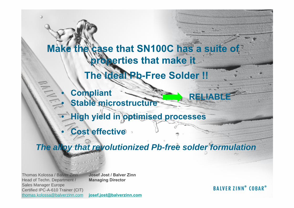
1 Thomas Kolossa / Balver Zinn Head of Techn. Department / Sales Manager Europe Certified IPC-A-610 Trainer (CIT) [email protected] Josef Jost / Balver Zinn Managing Director [email protected] Make the case that SN100C has a suite of properties that make it The Ideal Pb-Free Solder !! • Compliant • Stable microstructure RELIABLE • High yield in optimised processes • Cost effective The alloy that revolutionized Pb-free solder formulation
Transcript of Compliant RELIABLE Stable microstructure High yield …extra.ivf.se/eqs/dokument/Candor.pdf · New...
1
Thomas Kolossa / Balver ZinnHead of Techn. Department / Sales Manager EuropeCertified IPC-A-610 Trainer (CIT)[email protected]
Josef Jost / Balver ZinnManaging Director
Make the case that SN100C has a suite of properties that make it
The Ideal Pb-Free Solder !!• Compliant • Stable microstructure
RELIABLE
• High yield in optimised processes
• Cost effective
The alloy that revolutionized Pb-free solder formulation
2
• Balver Zinn Group
• Influence of micro alloying additions on metallurgical properties of lead free alloys
– Base– Micro alloying additions
• Germanium• Nickel
Agenda
3
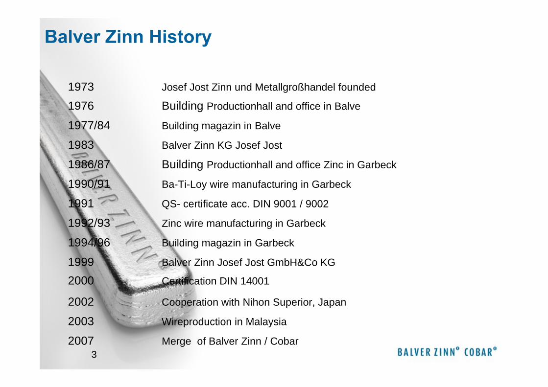
1973 Josef Jost Zinn und Metallgroßhandel founded
1976 Building Productionhall and office in Balve
1977/84 Building magazin in Balve
1983 Balver Zinn KG Josef Jost
1986/87 Building Productionhall and office Zinc in Garbeck
1990/91 Ba-Ti-Loy wire manufacturing in Garbeck
1991 QS- certificate acc. DIN 9001 / 9002
1992/93 Zinc wire manufacturing in Garbeck
1994/96 Building magazin in Garbeck
2000 Certification DIN 14001
2002 Cooperation with Nihon Superior, Japan
2003 Wireproduction in Malaysia
1999 Balver Zinn Josef Jost GmbH&Co KG
2007 Merge of Balver Zinn / Cobar
Balver Zinn History
4
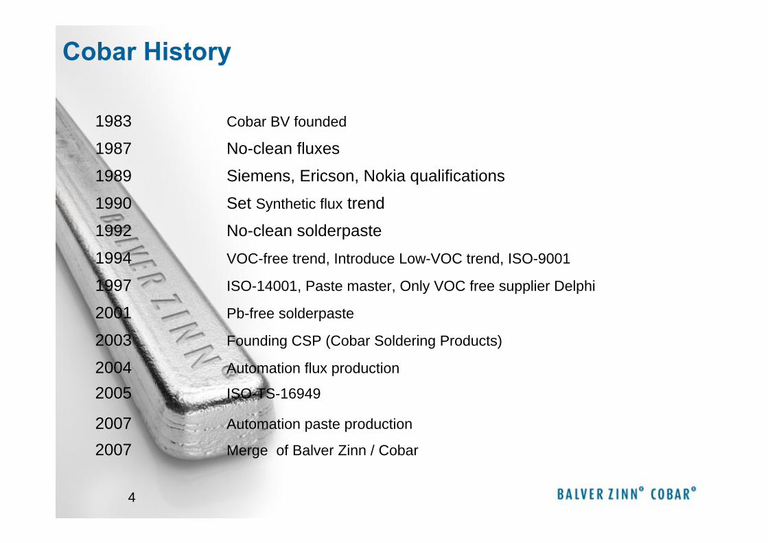
1983 Cobar BV founded
1987 No-clean fluxes
1989 Siemens, Ericson, Nokia qualifications
1990 Set Synthetic flux trend
1992 No-clean solderpaste
1994 VOC-free trend, Introduce Low-VOC trend, ISO-9001
1997 ISO-14001, Paste master, Only VOC free supplier Delphi
2001 Pb-free solderpaste
2003 Founding CSP (Cobar Soldering Products)
2005 ISO-TS-16949
2007 Automation paste production
2004 Automation flux production
2007 Merge of Balver Zinn / Cobar
Cobar History
5
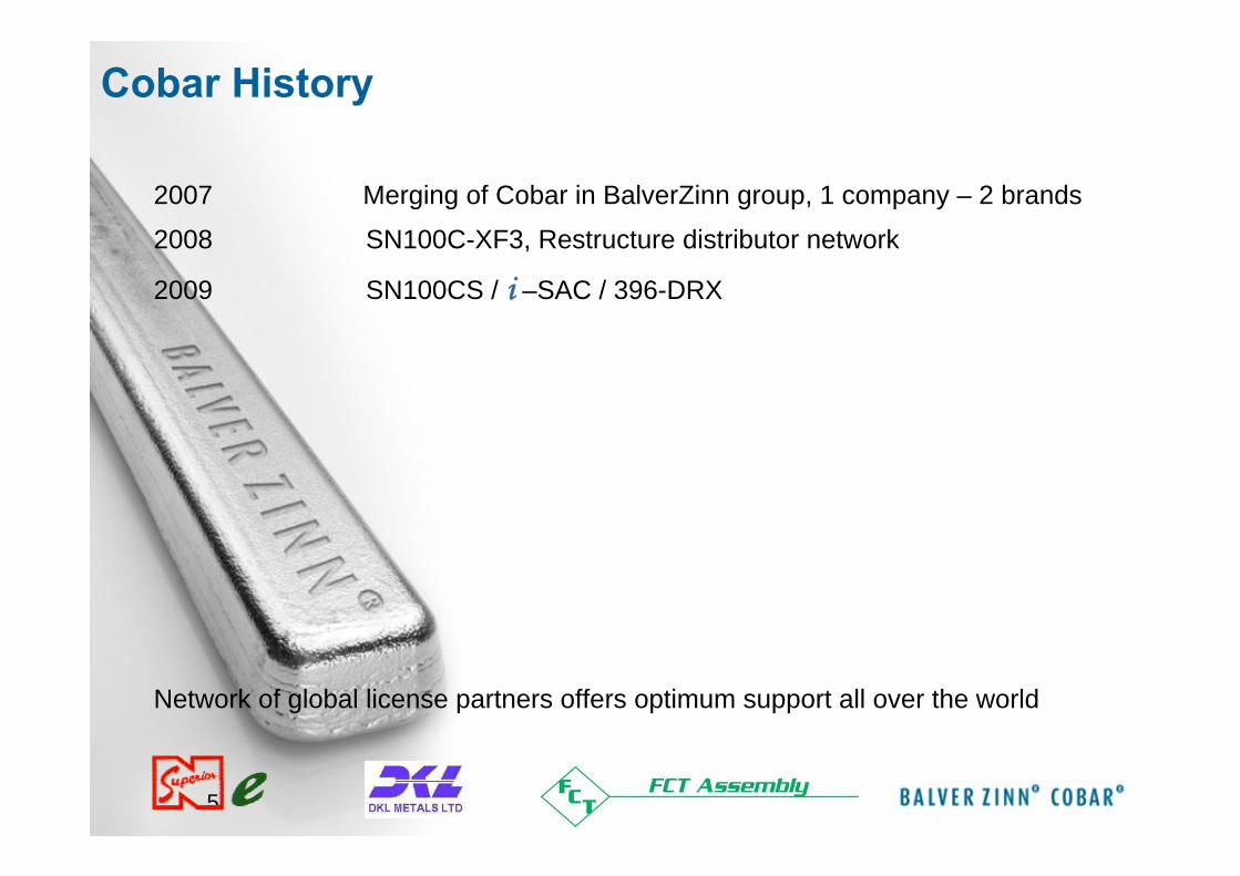
2007 Merging of Cobar in BalverZinn group, 1 company – 2 brands
2008 SN100C-XF3, Restructure distributor network
2009 SN100CS / i –SAC / 396-DRX
Network of global license partners offers optimum support all over the world
Cobar History
6
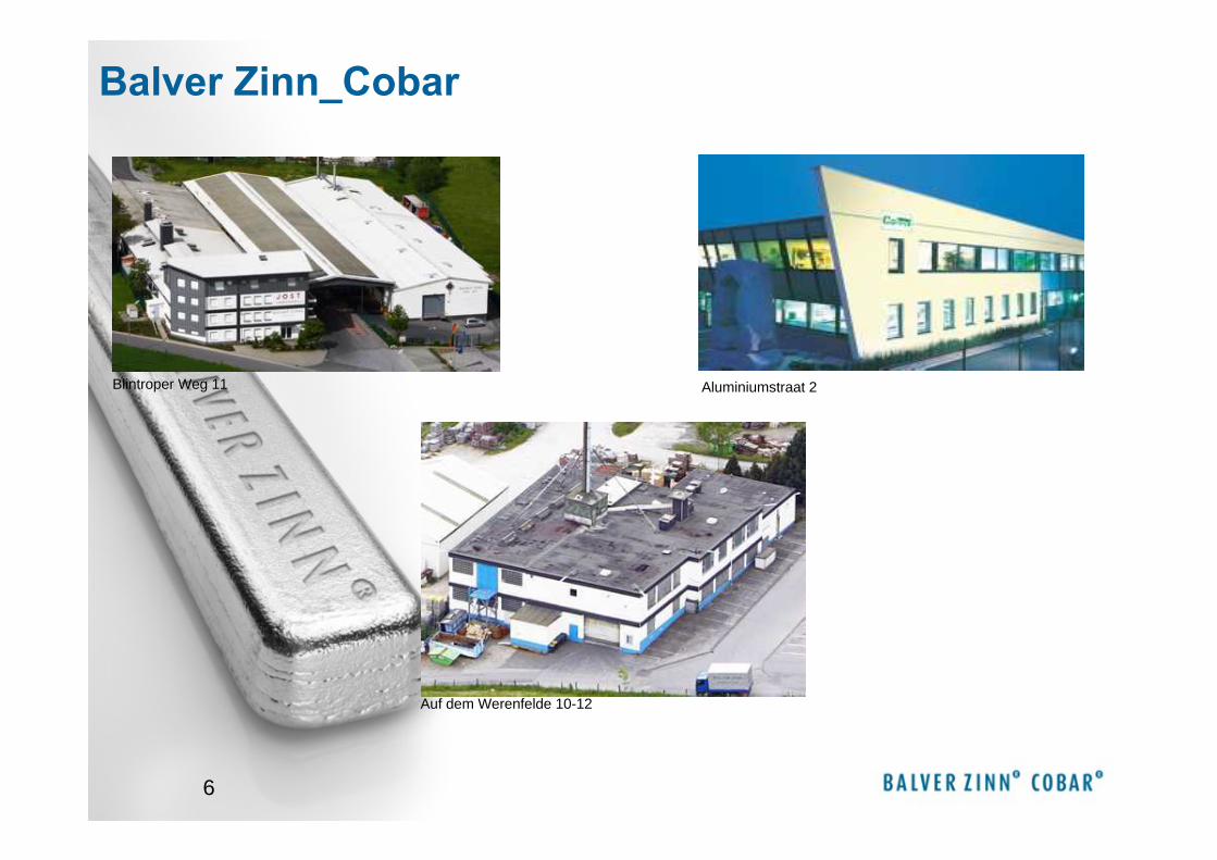
Blintroper Weg 11
Auf dem Werenfelde 10-12
Aluminiumstraat 2
Balver Zinn_Cobar
7
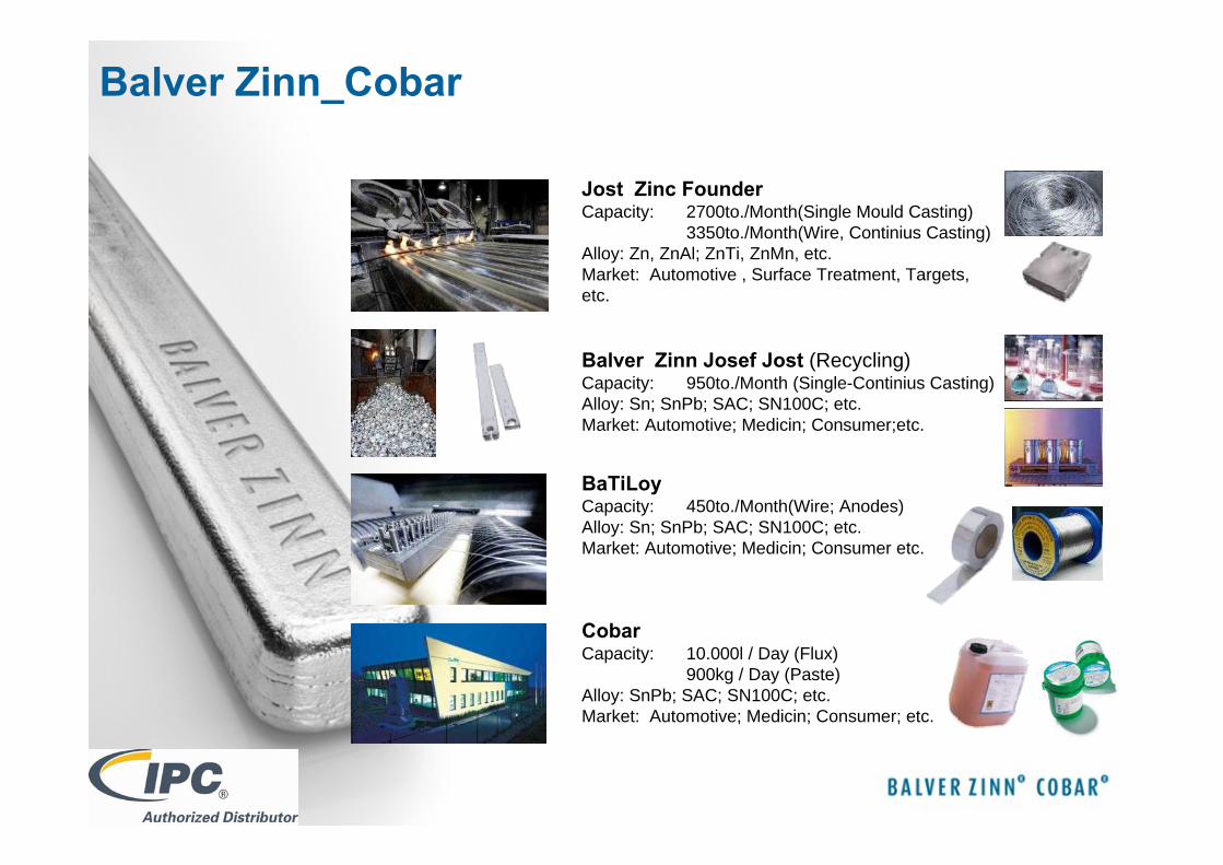
Jost Zinc FounderCapacity: 2700to./Month(Single Mould Casting)
3350to./Month(Wire, Continius Casting)Alloy: Zn, ZnAl; ZnTi, ZnMn, etc.Market: Automotive , Surface Treatment, Targets, etc.
Balver Zinn Josef Jost (Recycling)Capacity: 950to./Month (Single-Continius Casting)Alloy: Sn; SnPb; SAC; SN100C; etc.Market: Automotive; Medicin; Consumer;etc.
BaTiLoyCapacity: 450to./Month(Wire; Anodes)Alloy: Sn; SnPb; SAC; SN100C; etc.Market: Automotive; Medicin; Consumer etc.
CobarCapacity: 10.000l / Day (Flux)
900kg / Day (Paste)Alloy: SnPb; SAC; SN100C; etc.Market: Automotive; Medicin; Consumer; etc.
Balver Zinn_Cobar
8
KEY
Regional Headoffice
+ Production site
.
+
∇
+
+
+
⊗•
••
••
•
•
•
•••
•••
•
•••
••
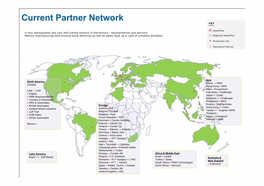
EuropeAustria • IVSBelgium ⊗ CobarBulgaria • KasiCzech Republic • PBTDenmark • Candor KemiskeEstonia • Candor OyFinland • Candor OyFrance • Dilectro • ArnaudGermany • Balver ZinnGreece • AsteriadisHungary • ATT HungaryIreland • DKLItaly • Tecnolab • CabelpiuLithuania/Latvia • Erbsloeh BalticNetherlands ⊗ CobarNorway • Candor ABPoland • C.H. ErbsloehRomania • ATT Hungary • LTHD Slovenia • ATT • AmtestSpain • Solder. Techn. • IndutecSweden • Candor ABUnited Kingdom • DKL
•
•
•
•
•
•
•
•
•
∇
+
+
Headoffice
Distributor/Partner•
⊗∇
AsiaChina - • WKKHong Kong • WKKIndia • ProsemtechIndonesia • ChallengerJapan ⊗ CobarMalaysia •+ ChallengerPhilippines • WKKRussia • DialElectroluxHong Kong ∇ CobarTaiwan •+ Eugene •WKKThailand •Korea • ChangwonVietnam • WKK
Africa & Middle EastIsrael • LantekTurkey • SelasSouth Africa • PEM TechnologiesNorth Africa • Hartech
Australia & New Zealand• Coltronics
Latin AmericaBrazil •+ Soft Metais
••
••
•• •
•North AmericaCanada
USA ∇ CSP• Captec• PMR Representatives• Torenko & Associates• SRS & Associates• Simlar Associates• Surface Mount solutions• Luff Tool• WJB Sales• Simlar Associates
Mexico •
A very distinguished and very well trained network of distributors / representatives and partnersRemote manufacturing sites ensures quick deliveries as well as safety back up in case of complete shutdown
Current Partner Network
9
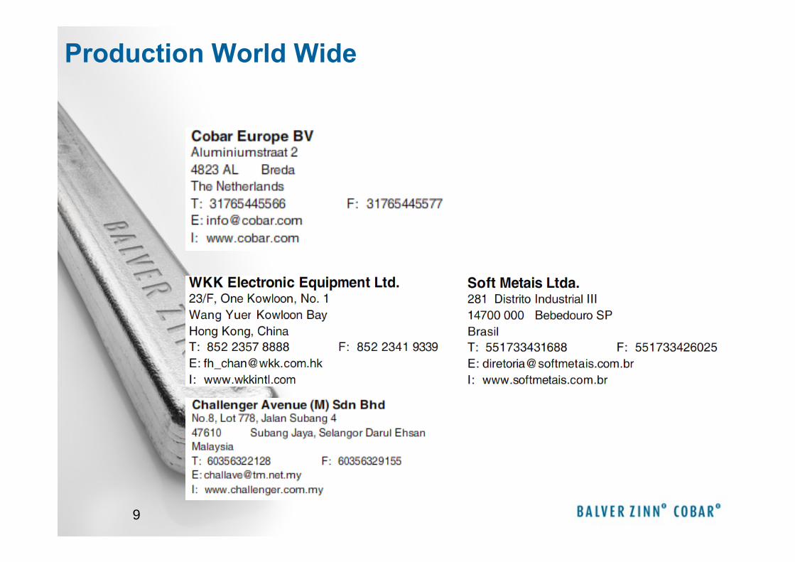
Production World Wide
10
• Productfamily SN100C™ (SnCu0,7Ni0,05Ge0,005)EU985486 / JP3152945 / US6180055
• SN100CS / SN100CeS (SnCu0,7NiGe0,01)• SN100CLS / SN100CLe+S (SnCu0,7NiGe0,01)
• Productfamily ii--SACSAC (SnAgCu) (SnAgCu) Iowa US6231691B1
• i-SAC105 (SnAg1,0Cu0,5Co0,0045Ge0,0045)• i-SAC205 (SnAg2,0Cu0,5Co0,0045Ge0,0045)• i-SAC305 (SnAg3,0Cu0,5Co0,0045Ge0,0045)• i-SAC387 (SnAg3,8Cu0,7Co0,0045Ge0,0045)
• Productfamily SCAN-Ge (SnAgCuNiGe) DE19816671C2 / US 6179935B1 / JP3296289
• SCAN-Ge (SnAg0-4Cu0-2Ni0,05Ge0,01)
Balver Zinn News
11
- BaseTin (Sn):
Copper (Cu):
Silver (Ag):
Derivates:
SnCu - Eutectic: MP 227 °C
SnAg - Eutectic: MP 221°C
SnAgCu - Eutectic: MP 217 °C
Non-Eutectic-Solders
- Micro alloying additionsGermanium
Nickel
Base and Micro alloying additions
12
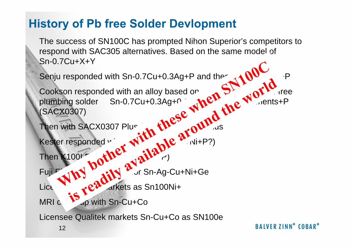
The success of SN100C has prompted Nihon Superior’s competitors to respond with SAC305 alternatives. Based on the same model of Sn-0.7Cu+X+Y
Senju responded with Sn-0.7Cu+0.3Ag+P and then Sn-0.7Cu+Ni+P
Cookson responded with an alloy based on old patent for a lead-free plumbing solder Sn-0.7Cu+0.3Ag+0.1Bi+Rare Earth Elements+P (SACX0307)
Then with SACX0307 Plus (+Ni), SACX0807 Plus
Kester responded with K100 (Sn-0.7Cu+Ni+P?)
Then K100LD (Sn-0.7Cu+Ni+Bi+P)
Fuji Electric got a patent for Sn-Ag-Cu+Ni+Ge
Licensee Felder markets as Sn100Ni+
MRI came up with Sn-Cu+Co
Licensee Qualitek markets Sn-Cu+Co as SN100e
Why bother with these when SN100C
is readily available around the world
History of Pb free Solder Devlopment
13
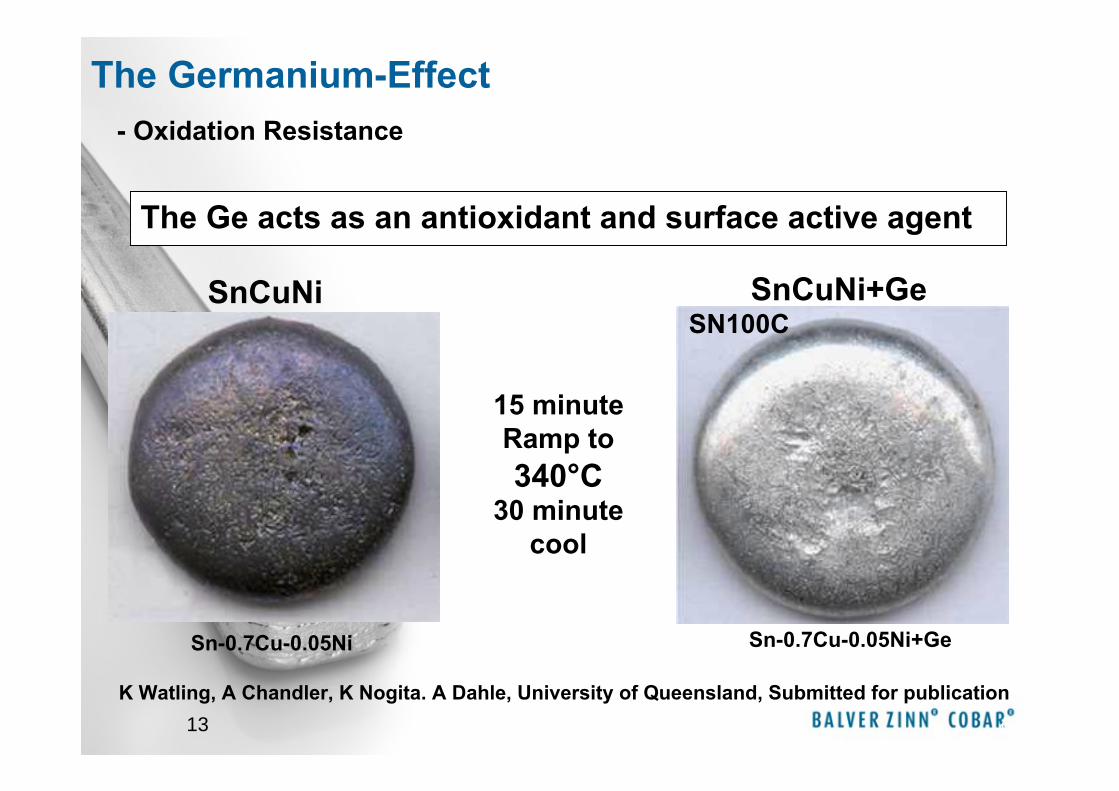
The Ge acts as an antioxidant and surface active agent
13
15 minute Ramp to 340°C
30 minute cool
Sn-0.7Cu-0.05Ni Sn-0.7Cu-0.05Ni+Ge
K Watling, A Chandler, K Nogita. A Dahle, University of Queensland, Submitted for publication
SnCuNi SnCuNi+Ge
- Oxidation Resistance
SN100C
The Germanium-Effect
14
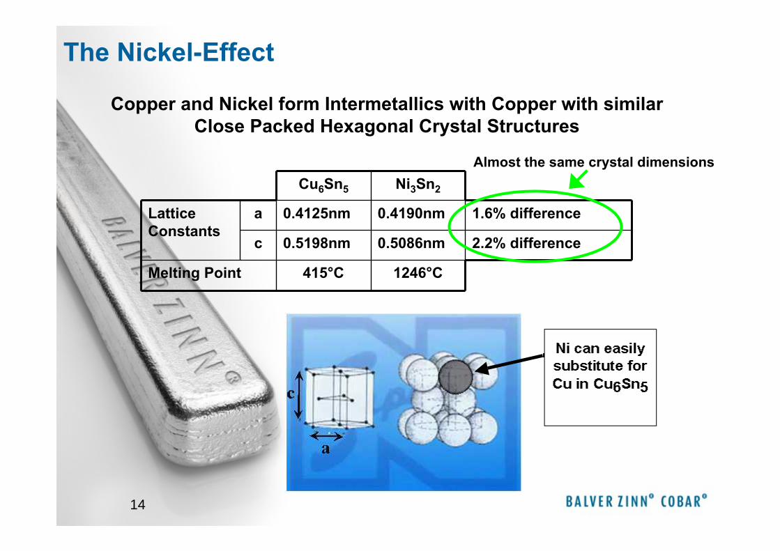
Cu6Sn5 Ni3Sn2
Lattice Constants
a 0.4125nm 0.4190nm 1.6% difference
c 0.5198nm 0.5086nm 2.2% difference
Melting Point 415°C 1246°C
Copper and Nickel form Intermetallics with Copper with similar Close Packed Hexagonal Crystal Structures
Almost the same crystal dimensions
The Nickel-Effect
15
20μm Ni
No Ni
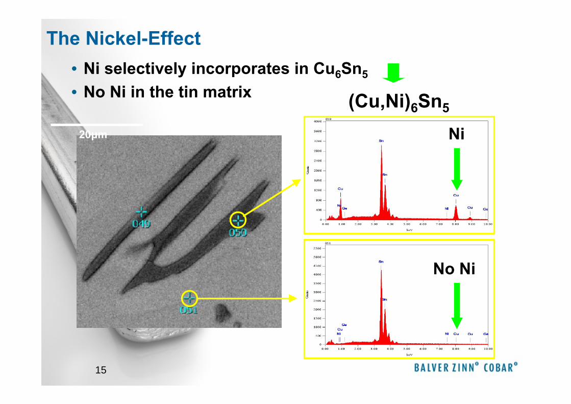
• Ni selectively incorporates in Cu6Sn5
• No Ni in the tin matrix
The Nickel-Effect
(Cu,Ni)6Sn5
16
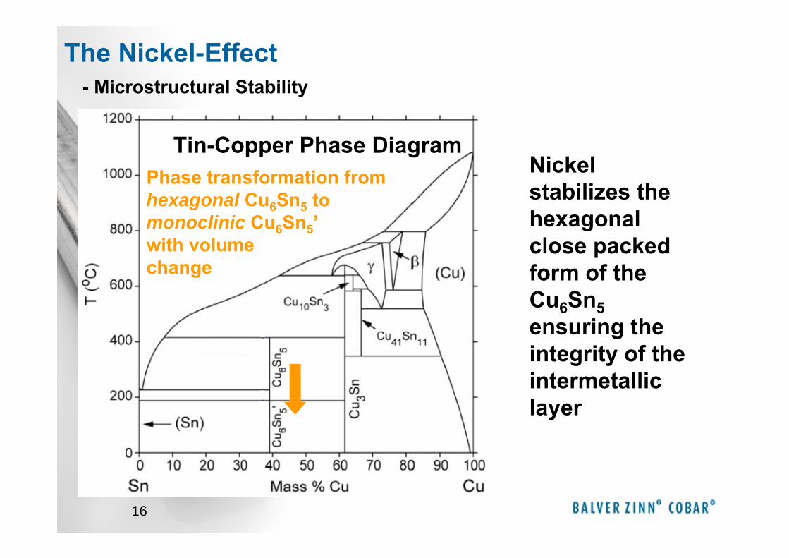
Tin-Copper Phase DiagramPhase transformation from hexagonal Cu6Sn5 to monoclinic Cu6Sn5’with volume change
Nickel stabilizes the hexagonal close packed form of the Cu6Sn5ensuring the integrity of the intermetallic layer
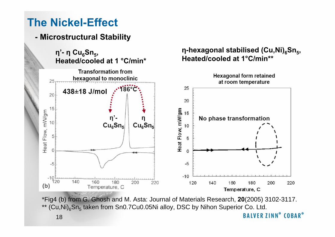
- Microstructural StabilityThe Nickel-Effect
17
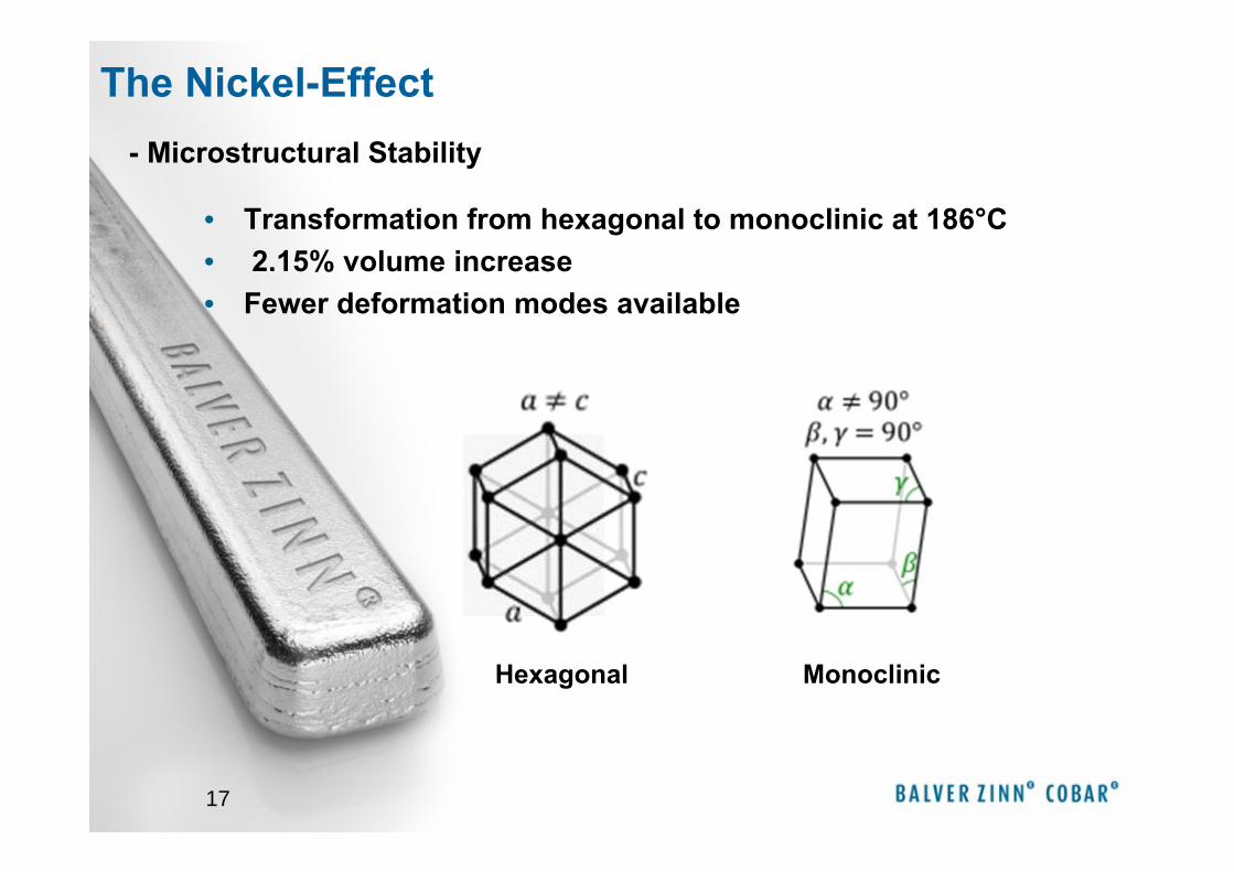
• Transformation from hexagonal to monoclinic at 186°C • 2.15% volume increase• Fewer deformation modes available
The Nickel-Effect
Hexagonal Monoclinic
- Microstructural Stability
18
The Nickel-Effect
η’- η Cu6Sn5, Heated/cooled at 1 °C/min*
η-hexagonal stabilised (Cu,Ni)6Sn5, Heated/cooled at 1°C/min**
*Fig4 (b) from G. Ghosh and M. Asta: Journal of Materials Research, 20(2005) 3102-3117.** (Cu,Ni)6Sn5 taken from Sn0.7Cu0.05Ni alloy, DSC by Nihon Superior Co. Ltd.
- Microstructural Stability
19
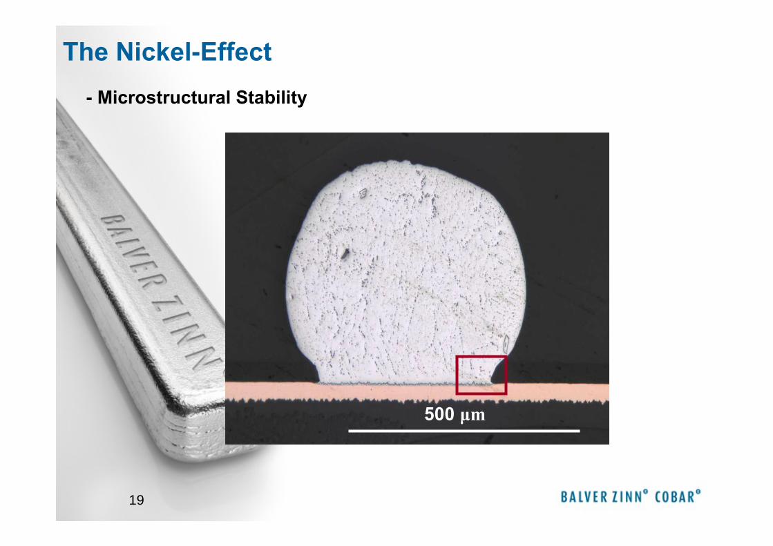
The Nickel-Effect
500 μm
- Microstructural Stability
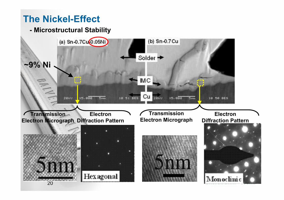
20
~9% Ni
Electron Diffraction Pattern
Electron Diffraction Pattern
Transmission Electron Micrograph
Transmission Electron Micrograph
- Microstructural StabilityThe Nickel-Effect

21 21
The Nickel-Effect
Sn0.7Cu0.05Ni
~ 3 at% Ni in (Cu,Ni)6Sn5
(Cu,Ni)6Sn5
Sn0.7Cu
Cu6Sn5
Cu6Sn5Cu6Sn5
Cu6Sn5
SnAg3Cu0,5
- Microstructural Stability
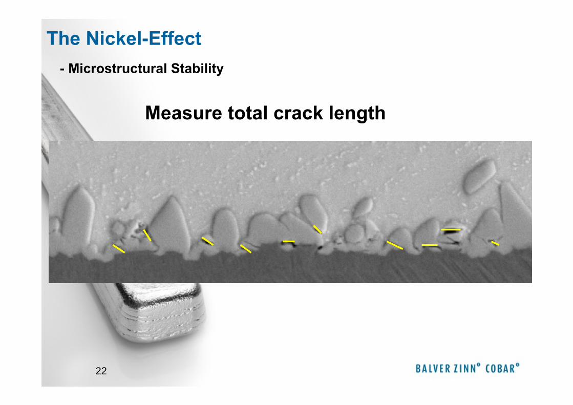
22
Measure total crack length
The Nickel-Effect- Microstructural Stability
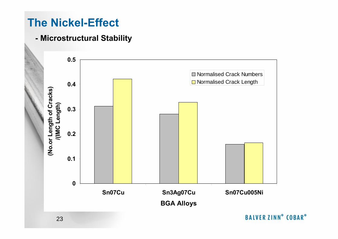
23
0
0.1
0.2
0.3
0.4
0.5
Sn07Cu Sn3Ag07Cu Sn07Cu005Ni
BGA Alloys
(No.
or L
engt
h of
Cra
cks)
/(IM
C L
engt
h)
Normalised Crack NumbersNormalised Crack Length
The Nickel-Effect- Microstructural Stability
24
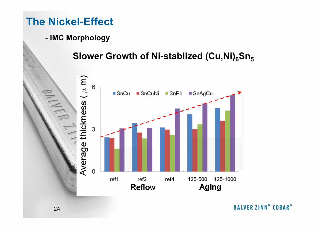
Slower Growth of Ni-stablized (Cu,Ni)6Sn5
The Nickel-Effect- IMC Morphology
25
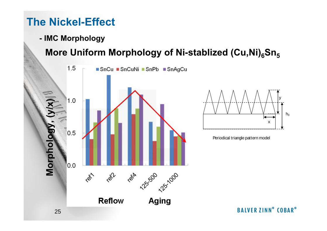
Periodical triangle pattern model
x
y
h0
More Uniform Morphology of Ni-stablized (Cu,Ni)6Sn5
The Nickel-Effect- IMC Morphology
Mor
phol
ogy,
(y/x
)
26
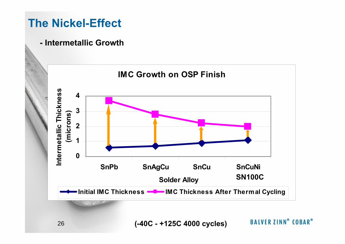
IMC Growth on OSP Finish
0
1
2
3
4
SnPb SnAgCu SnCu SnCuNi
Solder Alloy
Inte
rmet
allic
Thi
ckne
ss
(mic
rons
)
Initial IMC Thickness IMC Thickness After Thermal Cycling
SN100C
- Intermetallic Growth
(-40C - +125C 4000 cycles)
The Nickel-Effect

27
The Nickel-Effect- Intermetallic Growth
28
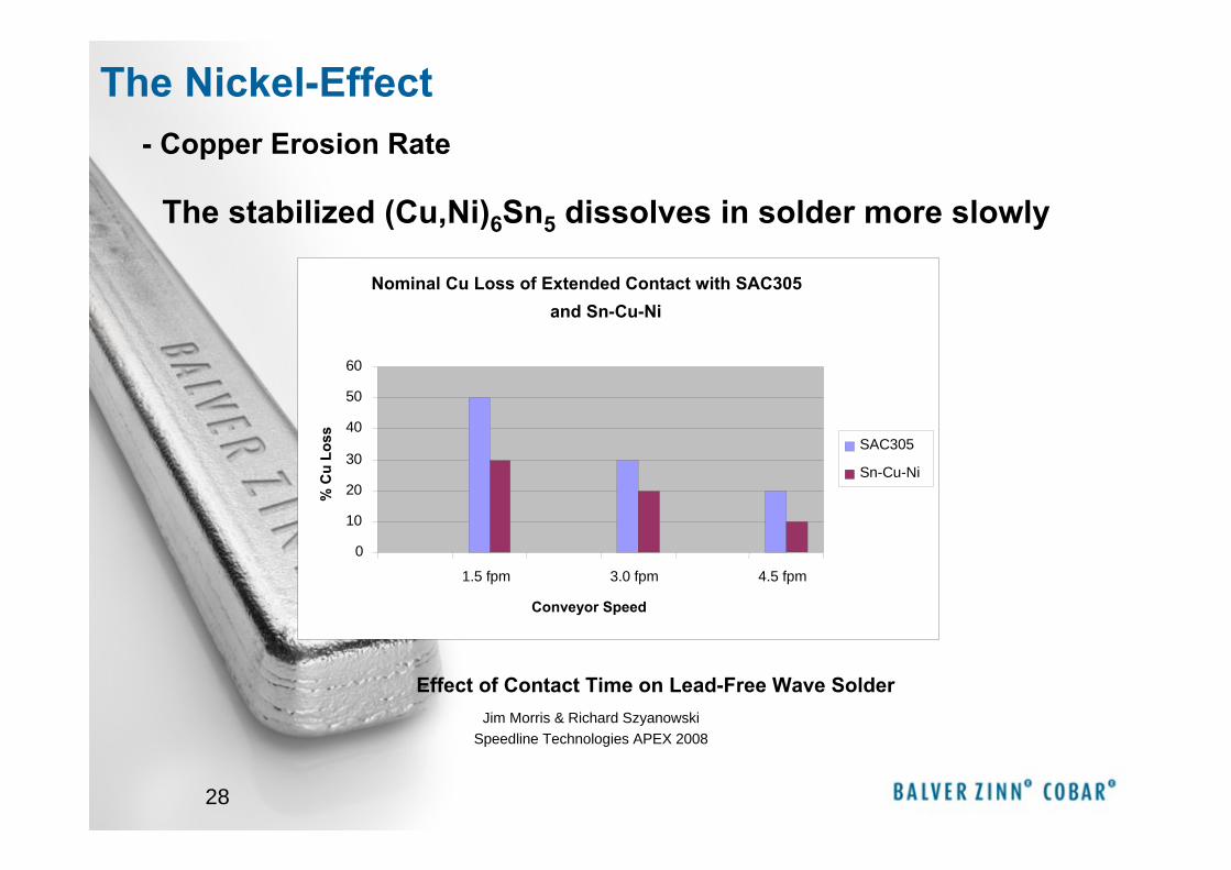
Nominal Cu Loss of Extended Contact with SAC305 and Sn-Cu-Ni
0
10
20
30
40
50
60
1.5 fpm 3.0 fpm 4.5 fpm
Conveyor Speed
% C
u Lo
ss SAC305
Sn-Cu-Ni
Effect of Contact Time on Lead-Free Wave SolderJim Morris & Richard Szyanowski
Speedline Technologies APEX 2008
- Copper Erosion Rate
The stabilized (Cu,Ni)6Sn5 dissolves in solder more slowly
The Nickel-Effect
29
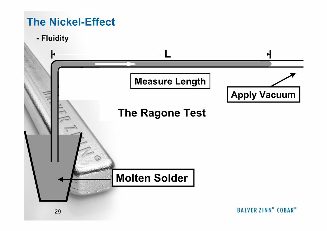
L
Measure LengthApply Vacuum
Molten Solder
The Ragone Test
- Fluidity
The Nickel-Effect
30
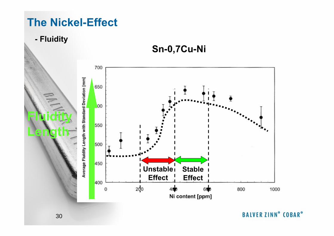
Stable Effect
Unstable Effect
Fluidity Length
- Fluidity
The Nickel-Effect
Sn-0,7Cu-Ni
31
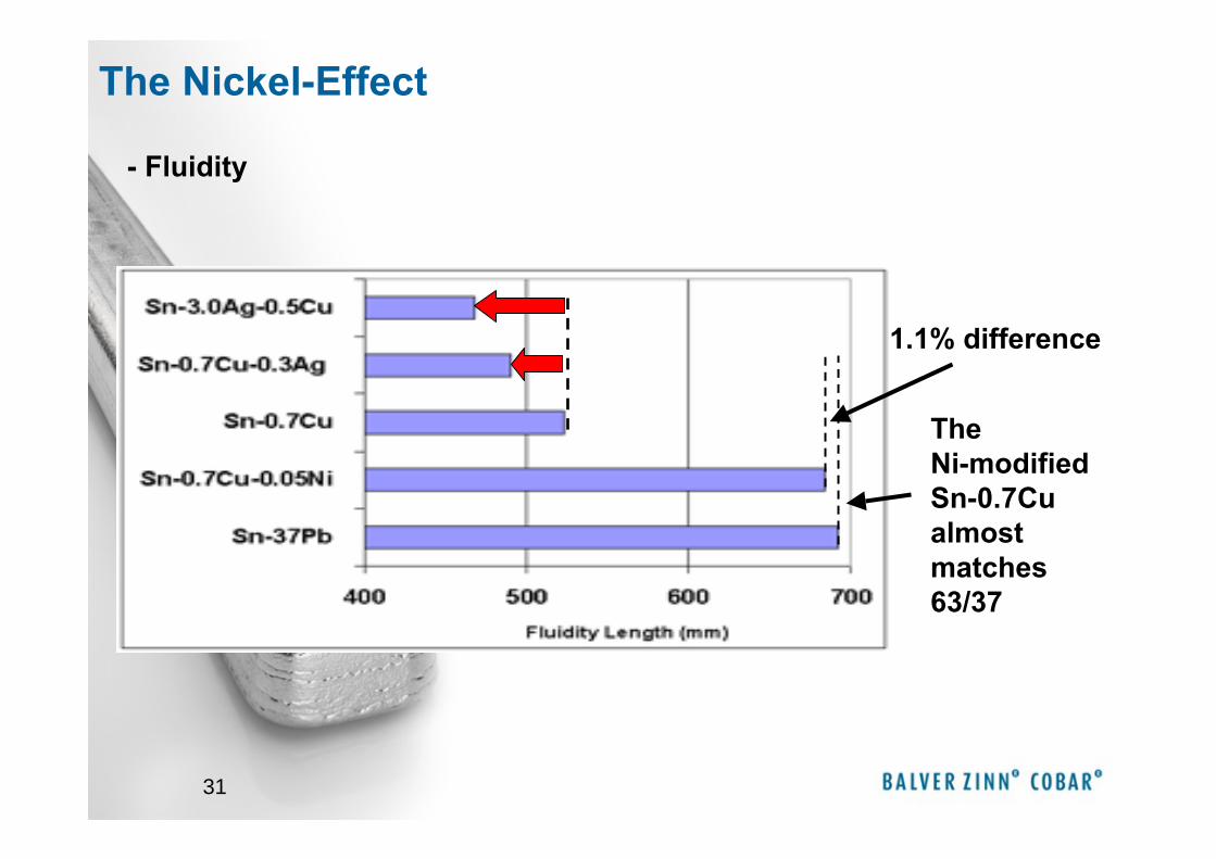
The Ni-modified Sn-0.7Cu almost matches 63/37
1.1% difference
- Fluidity
The Nickel-Effect
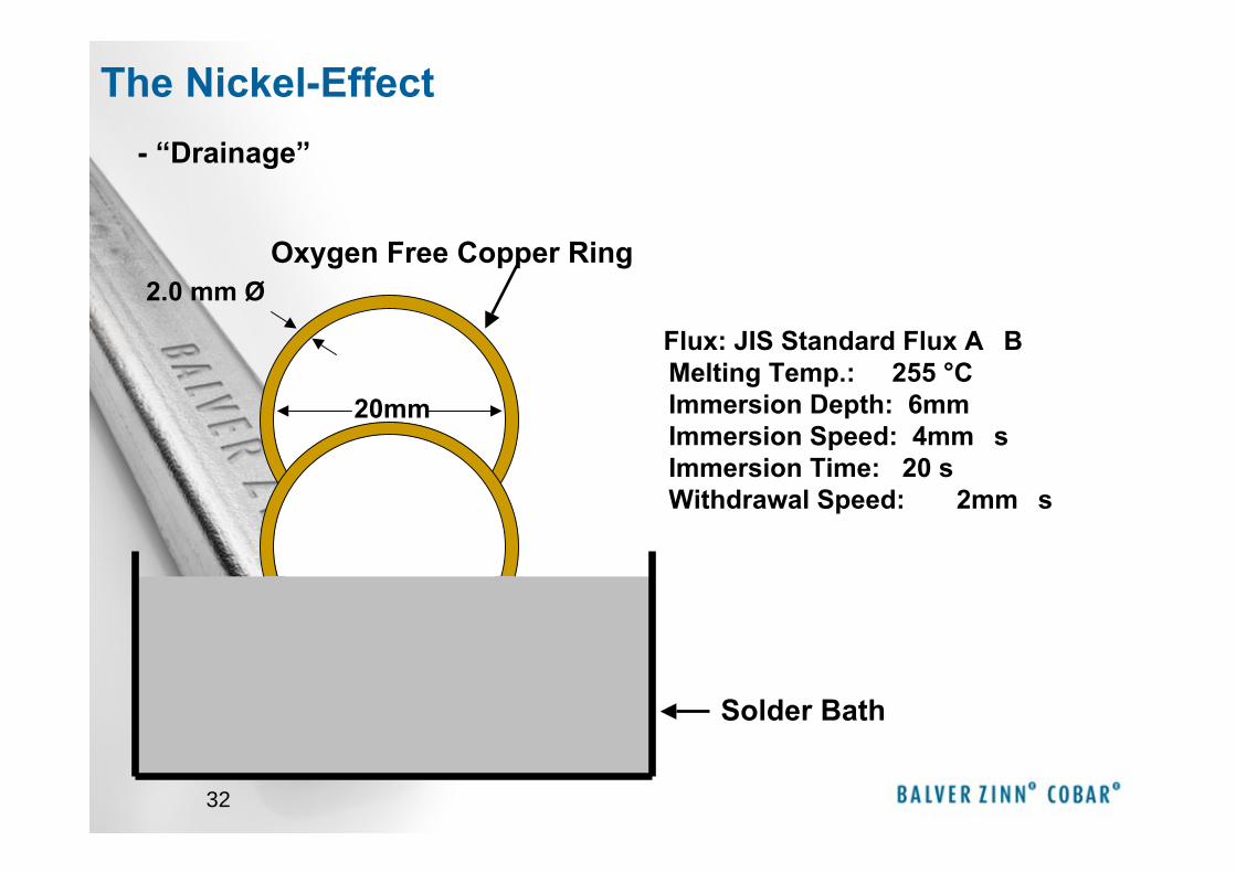
32
Oxygen Free Copper Ring
�Flux: JIS Standard Flux A�B���Melting Temp.: 255 °C��Immersion Depth: 6mm��Immersion Speed: 4mm�s��Immersion Time: 20 s��Withdrawal Speed: 2mm�s
20mm
2.0 mm Ø
Solder Bath
- “Drainage”
The Nickel-Effect
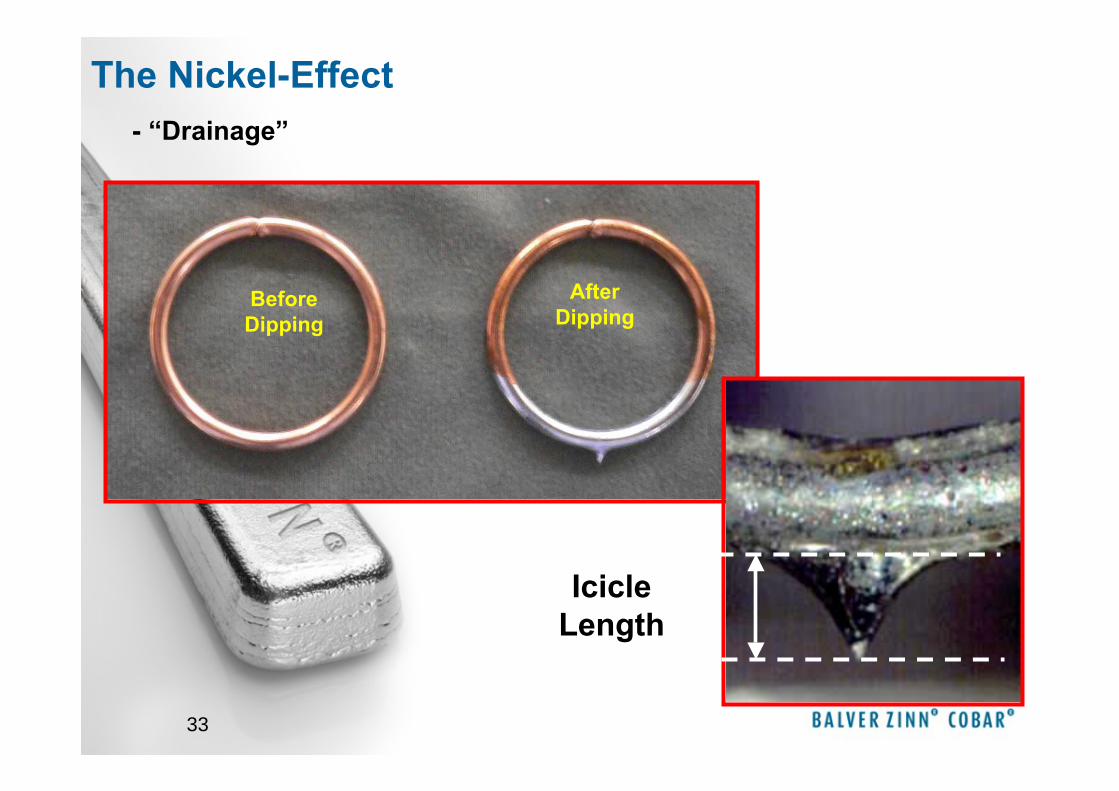
33
Before Dipping
After Dipping
Icicle Length
- “Drainage”
The Nickel-Effect
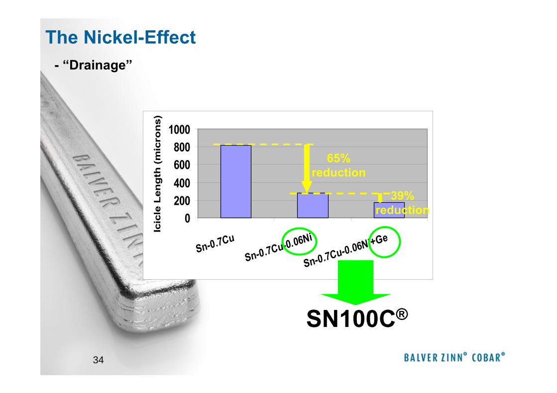
34
0200400600800
1000
Sn-0.7Cu
Sn-0.7Cu-0.06Ni
Sn-0.7Cu-0.06Ni+Ge
Icic
le L
eng
th (
mic
ron
s)65%
reduction
39% reduction
SN100C®
- “Drainage”
The Nickel-Effect
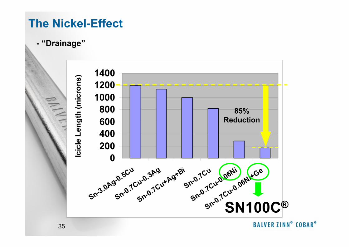
35
0200400600800
100012001400
Sn-3.0Ag-0.5Cu
Sn-0.7Cu-0.3Ag
Sn-0.7Cu+Ag+Bi
Sn-0.7Cu
Sn-0.7Cu-0.06Ni
Sn-0.7Cu-0.06Ni+Ge
Icic
le L
engt
h (m
icro
ns)
85% Reduction
SN100C®
- “Drainage”
The Nickel-Effect
36
Processparameter
37
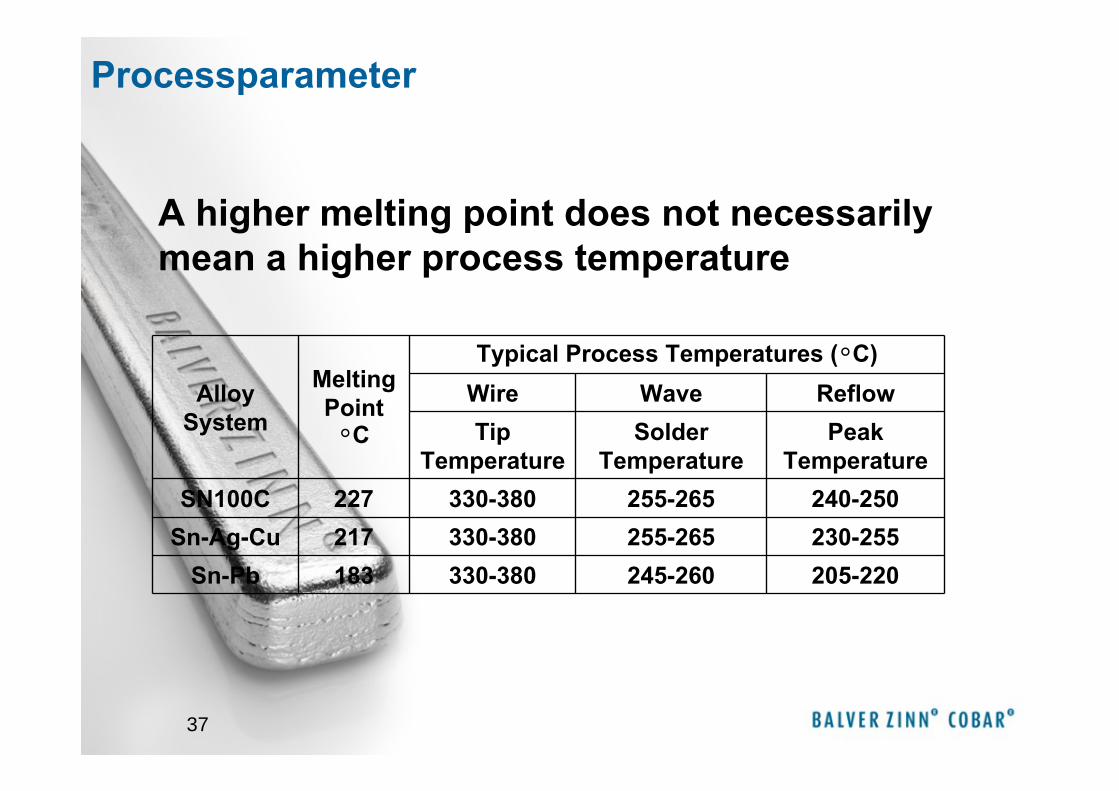
Alloy System
Melting Point
°C
Typical Process Temperatures (°C)Wire Wave ReflowTip
TemperatureSolder
TemperaturePeak
TemperatureSN100C 227 330-380 255-265 240-250
Sn-Ag-Cu 217 330-380 255-265 230-255Sn-Pb 183 330-380 245-260 205-220
A higher melting point does not necessarily mean a higher process temperature
Processparameter
38
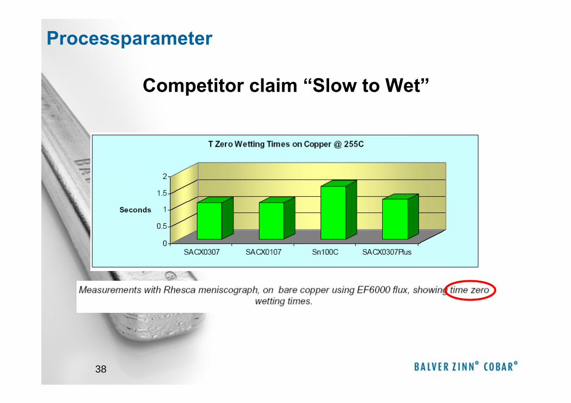
Competitor claim “Slow to Wet”
Processparameter
39
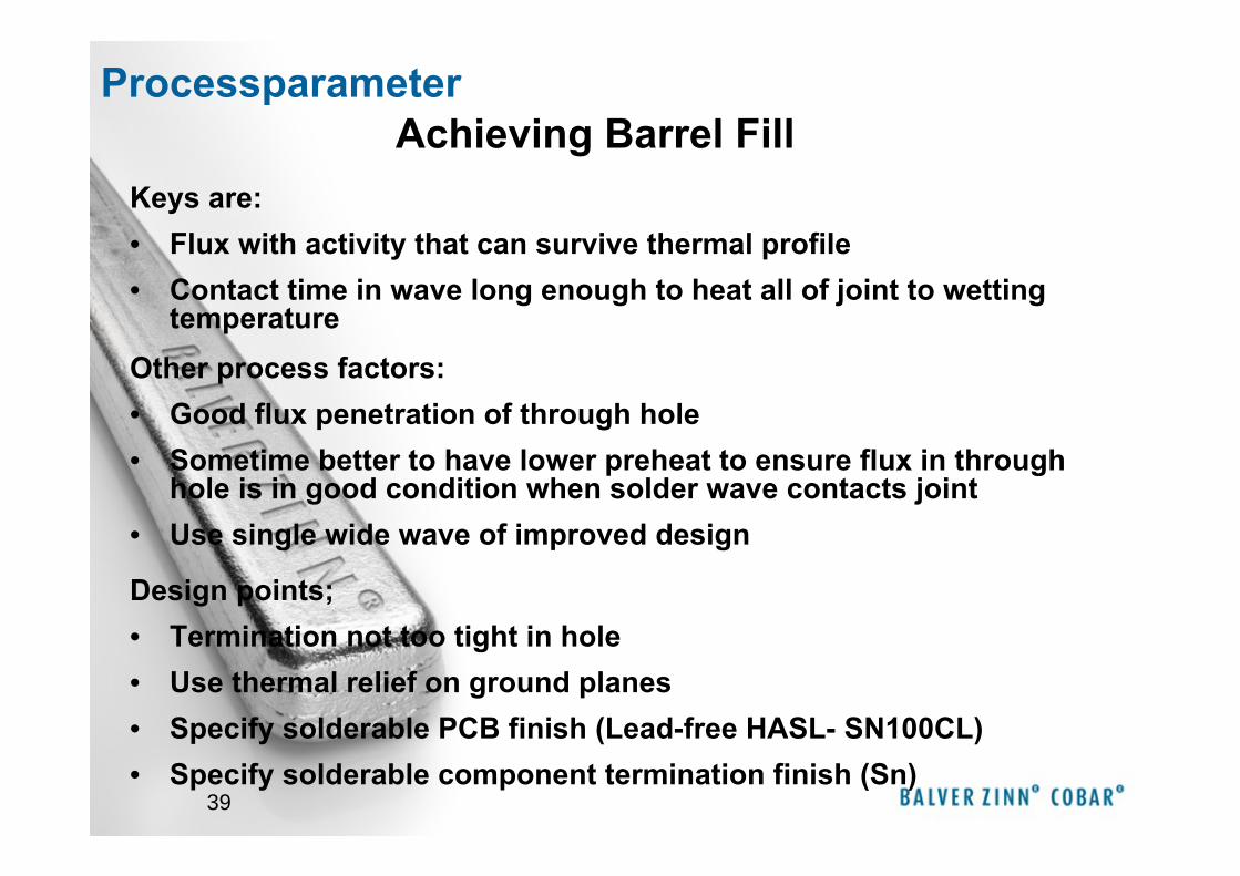
Keys are:• Flux with activity that can survive thermal profile • Contact time in wave long enough to heat all of joint to wetting
temperatureOther process factors:• Good flux penetration of through hole• Sometime better to have lower preheat to ensure flux in through
hole is in good condition when solder wave contacts joint• Use single wide wave of improved design
Design points; • Termination not too tight in hole• Use thermal relief on ground planes• Specify solderable PCB finish (Lead-free HASL- SN100CL)• Specify solderable component termination finish (Sn)
Achieving Barrel FillProcessparameter
40
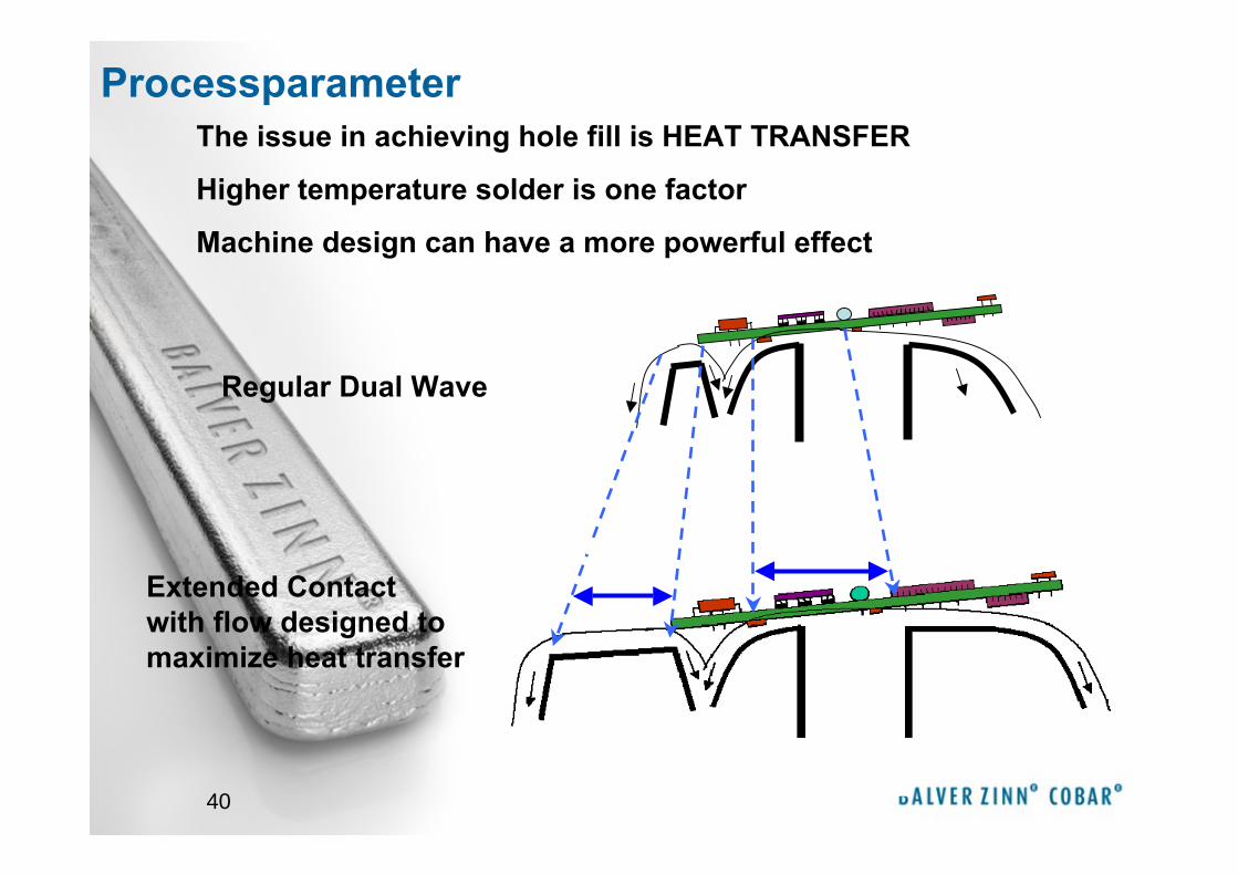
Regular Dual Wave
Extended Contact with flow designed to maximize heat transfer
Dual Wave
The issue in achieving hole fill is HEAT TRANSFER
Higher temperature solder is one factor
Machine design can have a more powerful effect
Processparameter
41
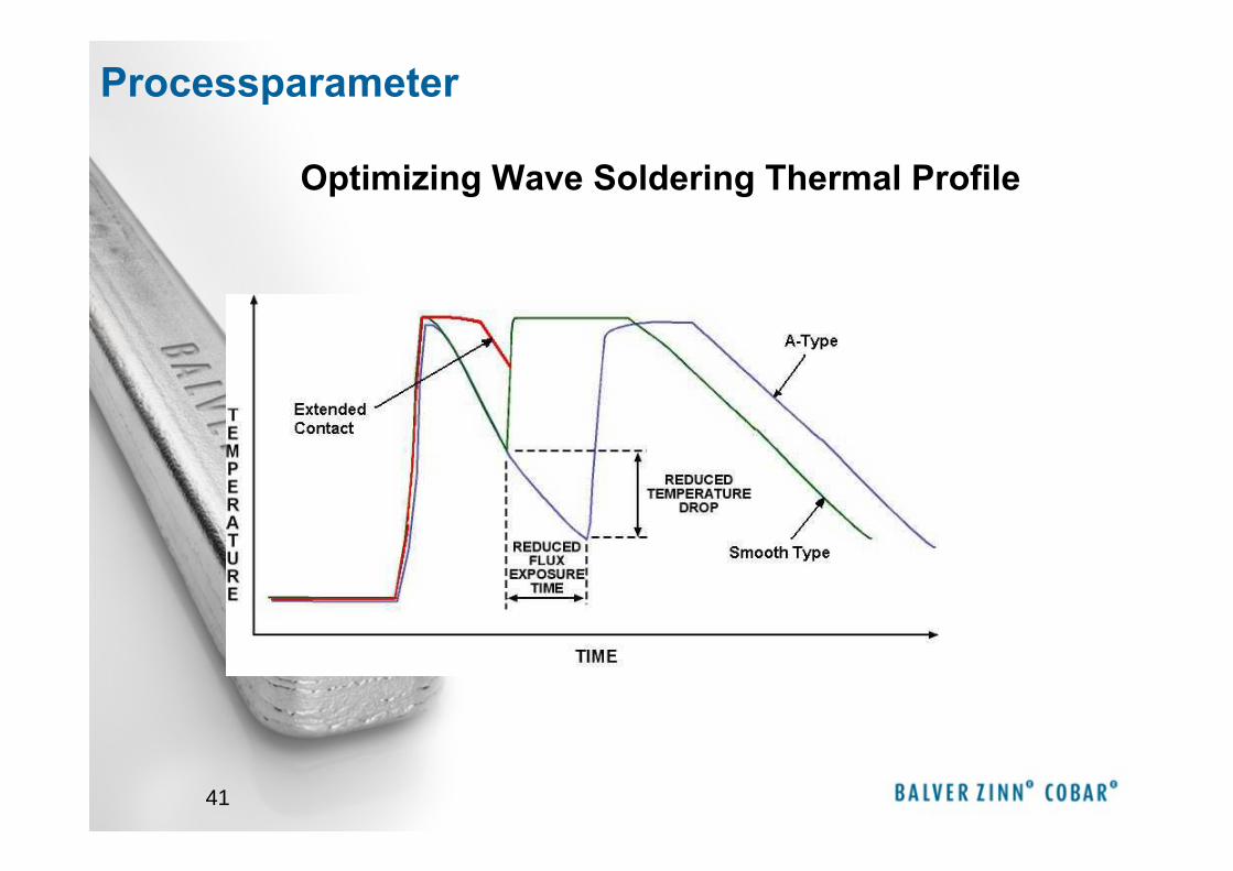
Optimizing Wave Soldering Thermal Profile
Processparameter
42
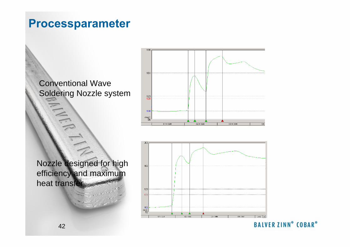
Conventional Wave Soldering Nozzle system
Nozzle designed for high efficiency and maximum heat transfer
Processparameter

43
Processparameter
44
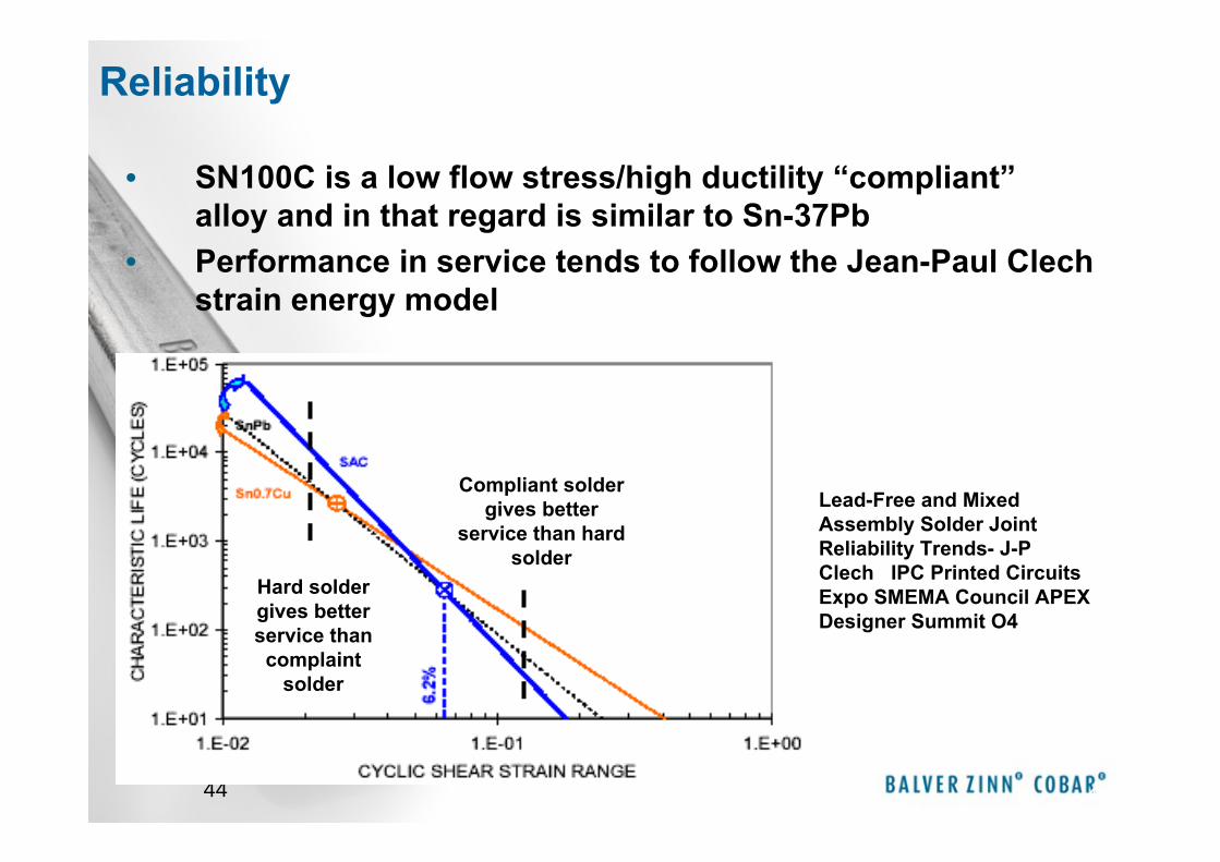
• SN100C is a low flow stress/high ductility “compliant”alloy and in that regard is similar to Sn-37Pb
• Performance in service tends to follow the Jean-Paul Clech strain energy model
44
Lead-Free and Mixed Assembly Solder Joint Reliability Trends- J-P Clech IPC Printed Circuits Expo SMEMA Council APEX Designer Summit O4
Hard solder gives better service than complaint
solder
Compliant solder gives better
service than hard solder
Reliability
45
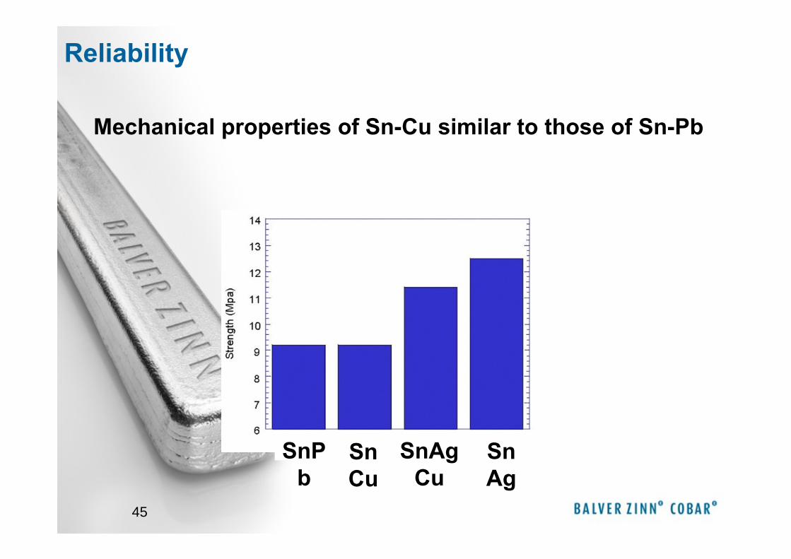
SnPb
SnAgCu
SnAg
SnCu
Mechanical properties of Sn-Cu similar to those of Sn-Pb
Reliability
46
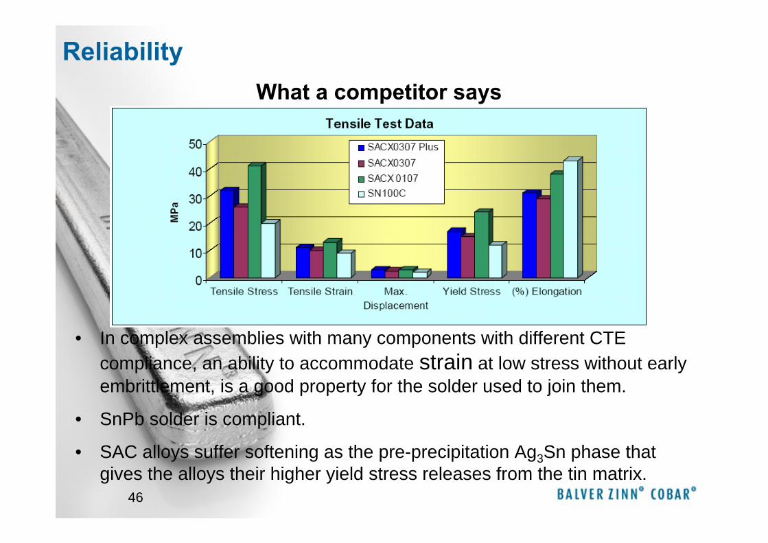
What a competitor says
• In complex assemblies with many components with different CTE compliance, an ability to accommodate strain at low stress without early embrittlement, is a good property for the solder used to join them.
• SnPb solder is compliant.
• SAC alloys suffer softening as the pre-precipitation Ag3Sn phase that gives the alloys their higher yield stress releases from the tin matrix.
Reliability
47
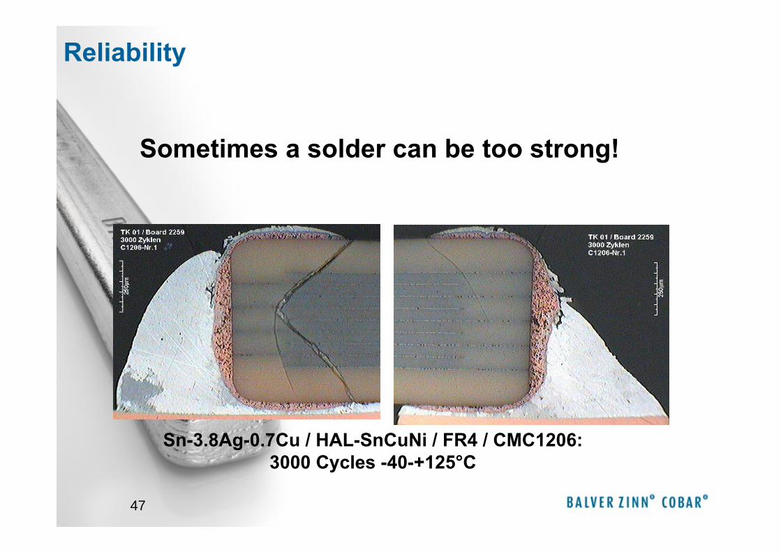
Sn-3.8Ag-0.7Cu / HAL-SnCuNi / FR4 / CMC1206: 3000 Cycles -40-+125°C
Sometimes a solder can be too strong!
Reliability
48
Reliability
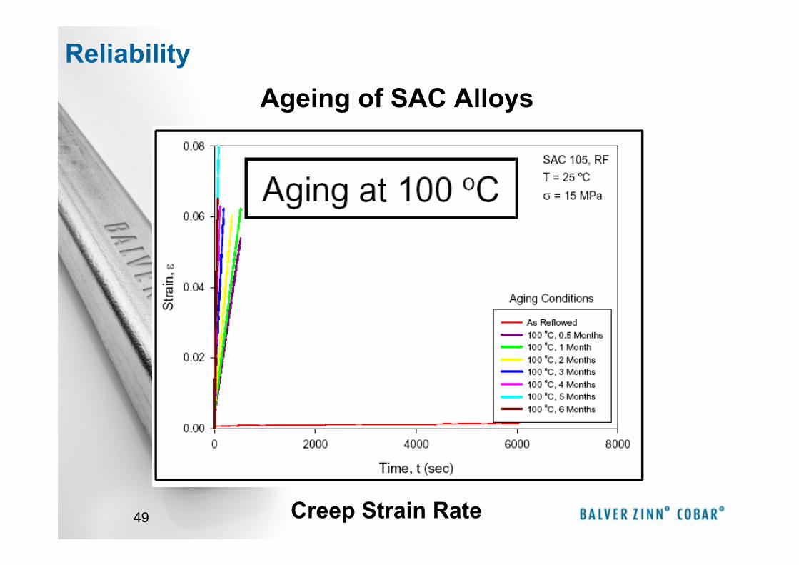
49
Ageing of SAC Alloys
Creep Strain Rate
Reliability
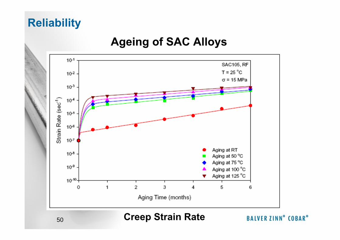
50
Ageing of SAC Alloys
Creep Strain Rate
Reliability
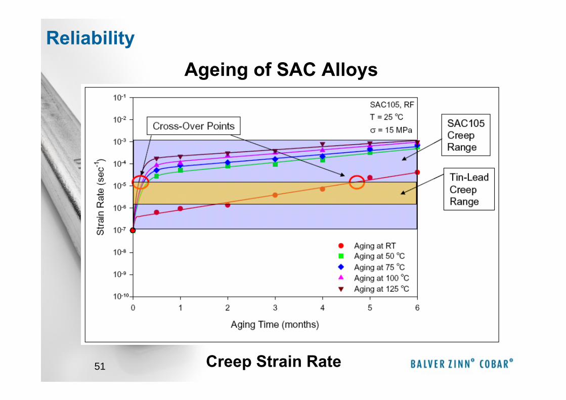
51
Ageing of SAC Alloys
Creep Strain Rate
Reliability

52
Ageing of SAC Alloys
Creep Strain Rate
Reliability
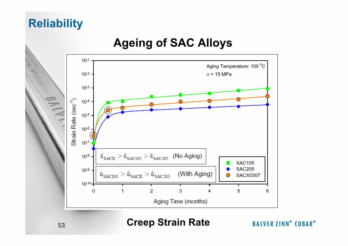
53
Ageing of SAC Alloys
Creep Strain Rate
Reliability
54
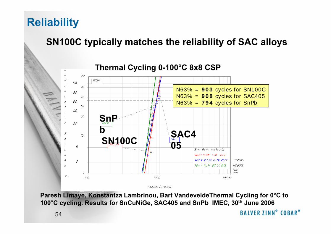
SN100C typically matches the reliability of SAC alloys
54
N63% = 903 cycles for SN100CN63% = 908 cycles for SAC405N63% = 794 cycles for SnPb
Paresh Limaye, Konstantza Lambrinou, Bart VandeveldeThermal Cycling for 0°C to 100°C cycling. Results for SnCuNiGe, SAC405 and SnPb IMEC, 30th June 2006
Thermal Cycling 0-100°C 8x8 CSP
SnPbSN100C
SAC405
Reliability

55
• Components– Leaded -- 44 Pin Thin Scale Outline Package (TSOP)
– Leadless -- 2512 Thin Film Chip Resistor– Solder Ball -- 96 Pin Chip Scale Package (CSP)
• Test Methods– Vibration to 30G– Thermal cycling -40 – 125°C
55
DfR Solutions Testing
Alloys Tested: SN100C, SAC305 SnPb
Reliability
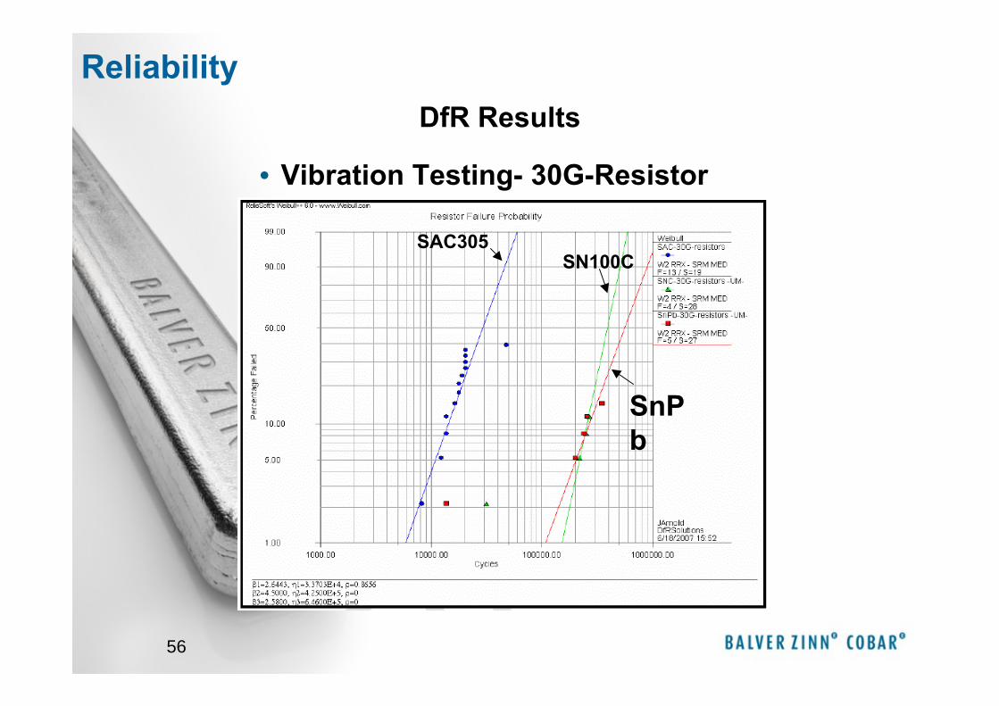
56
• Vibration Testing- 30G-Resistor
SAC305SN100C
SnPb
DfR ResultsReliability
57
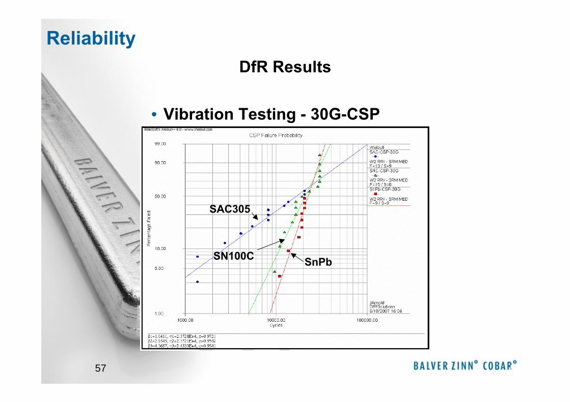
• Vibration Testing - 30G-CSP
57
SAC305
SN100C SnPb
DfR ResultsReliability
58
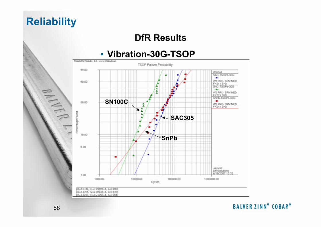
• Vibration-30G-TSOP
58
SAC305
SN100C
SnPb
DfR ResultsReliability
59
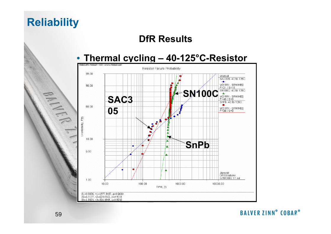
• Thermal cycling – 40-125°C-Resistor
59
SAC305
SN100C
SnPb
DfR ResultsReliability
60
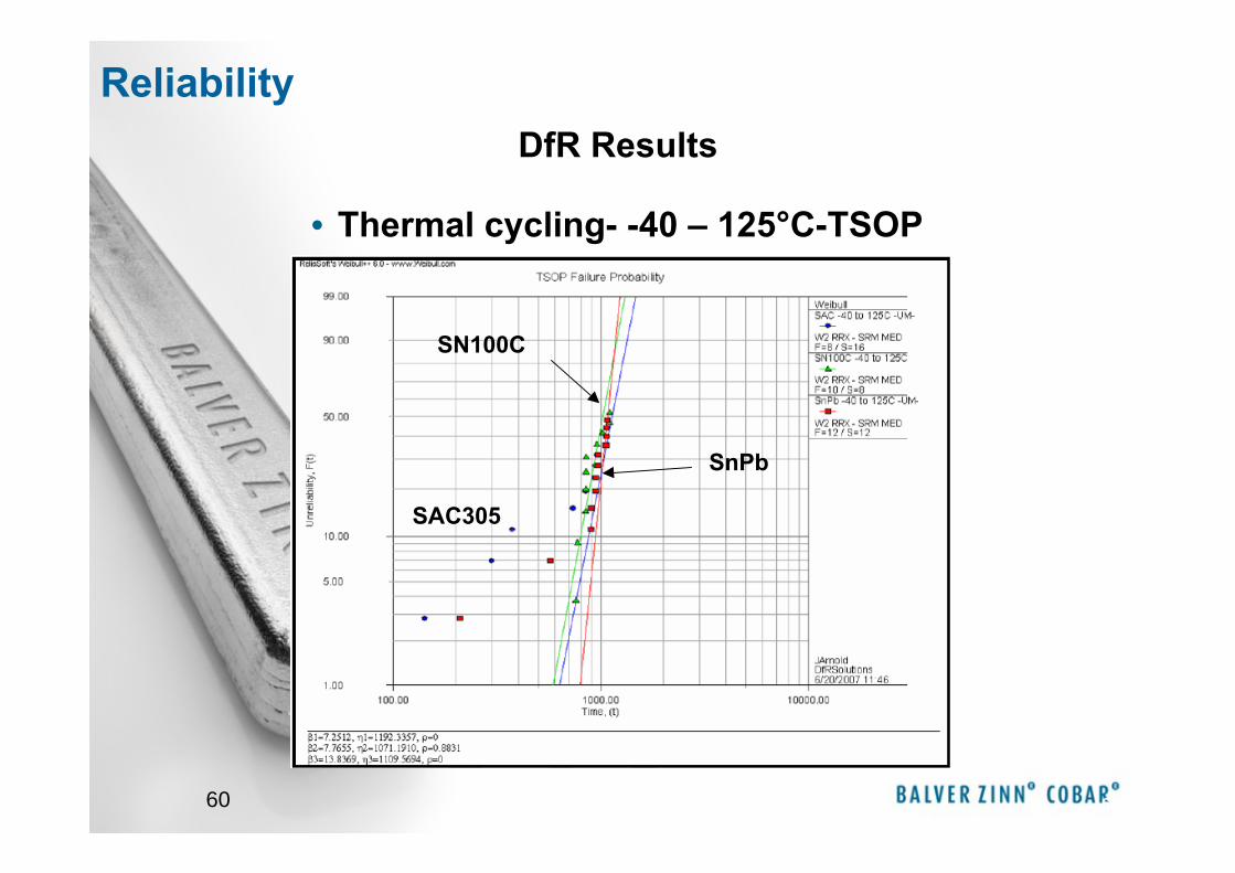
• Thermal cycling- -40 – 125°C-TSOP
60
SAC305
SN100C
SnPb
DfR ResultsReliability
61 61
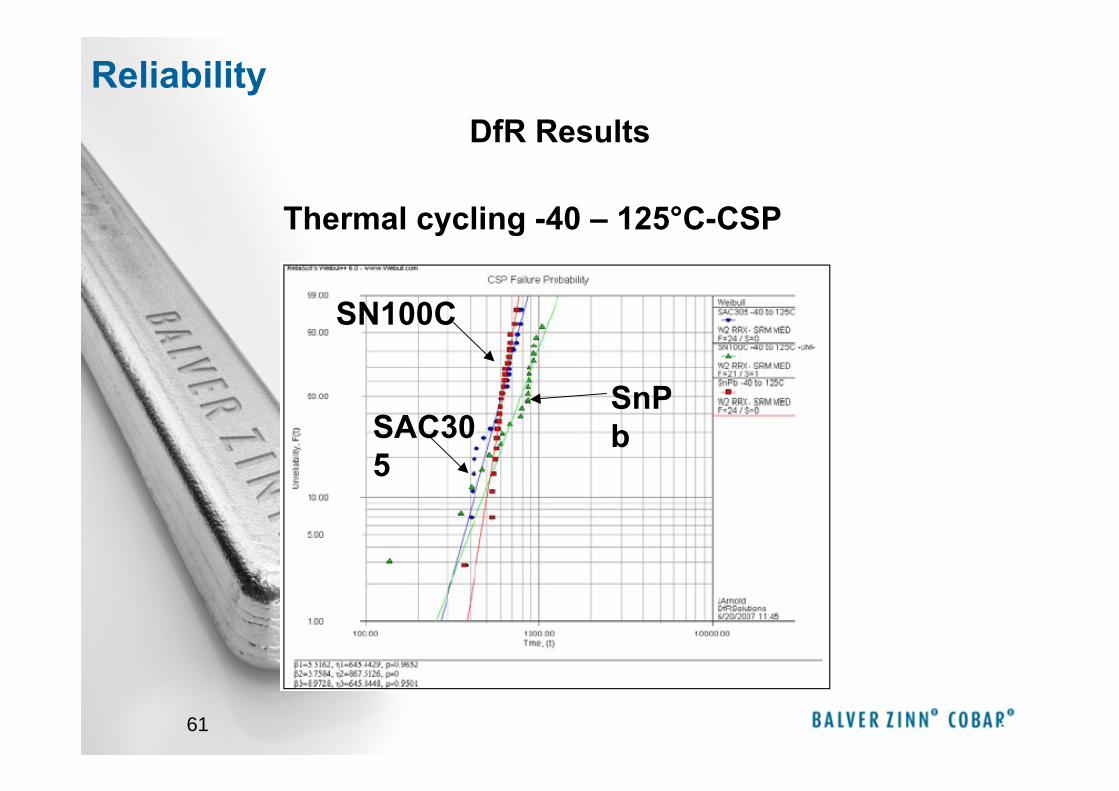
SAC305
SN100C
SnPb
Thermal cycling -40 – 125°C-CSP
DfR ResultsReliability
62
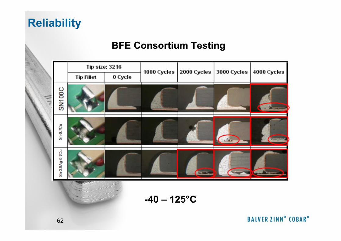
BFE Consortium Testing
-40 – 125°C
Reliability
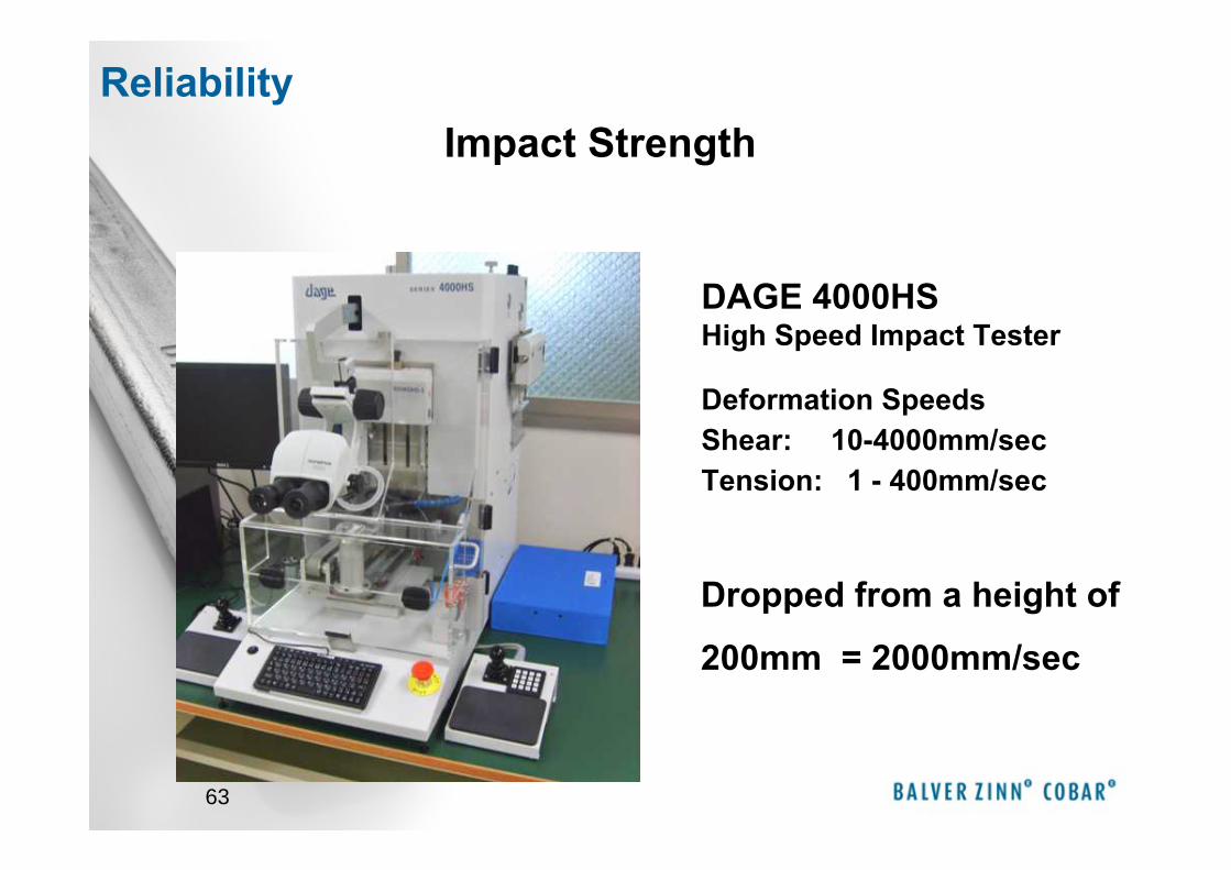
63
DAGE 4000HS High Speed Impact Tester
Deformation SpeedsShear: 10-4000mm/secTension: 1 - 400mm/sec
Impact Strength
Dropped from a height of
200mm = 2000mm/sec
Reliability
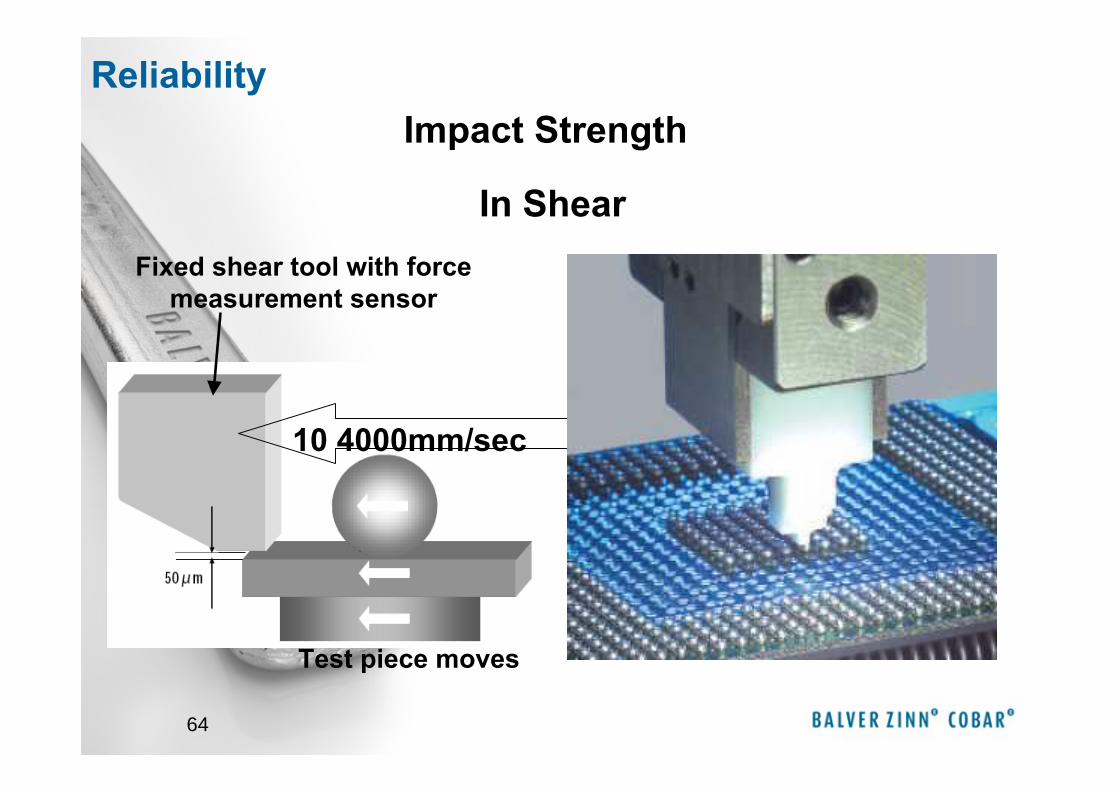
64
In Shear
Test piece moves
Fixed shear tool with force measurement sensor
10 4000mm/sec
Impact Strength Reliability
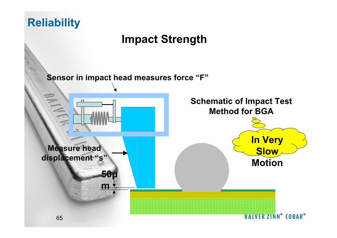
65
Schematic of Impact Test Method for BGA
Sensor in impact head measures force “F”
Measure head displacement “s”
50μm
In Very Slow
Motion
Impact Strength Reliability
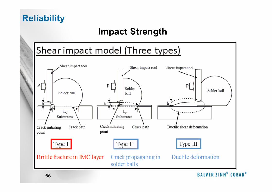
66
Impact Strength Reliability
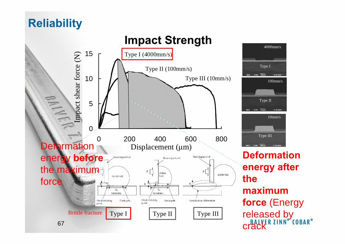
67
(c)
Type III
Type II
Type I
10mm/s
100mm/s
4000mm/s
Impa
ct s
hear
forc
e (N
)
0
5
10
15
0 200 400 600 800
Type III (10mm/s) Type II (100mm/s)
Type I (4000mm/s)
Displacement (μm)
Type I Type II Type III
Deformation energy beforethe maximum force
Deformation energy after the maximum force (Energy released by crack
Brittle fracture
Impact Strength Reliability
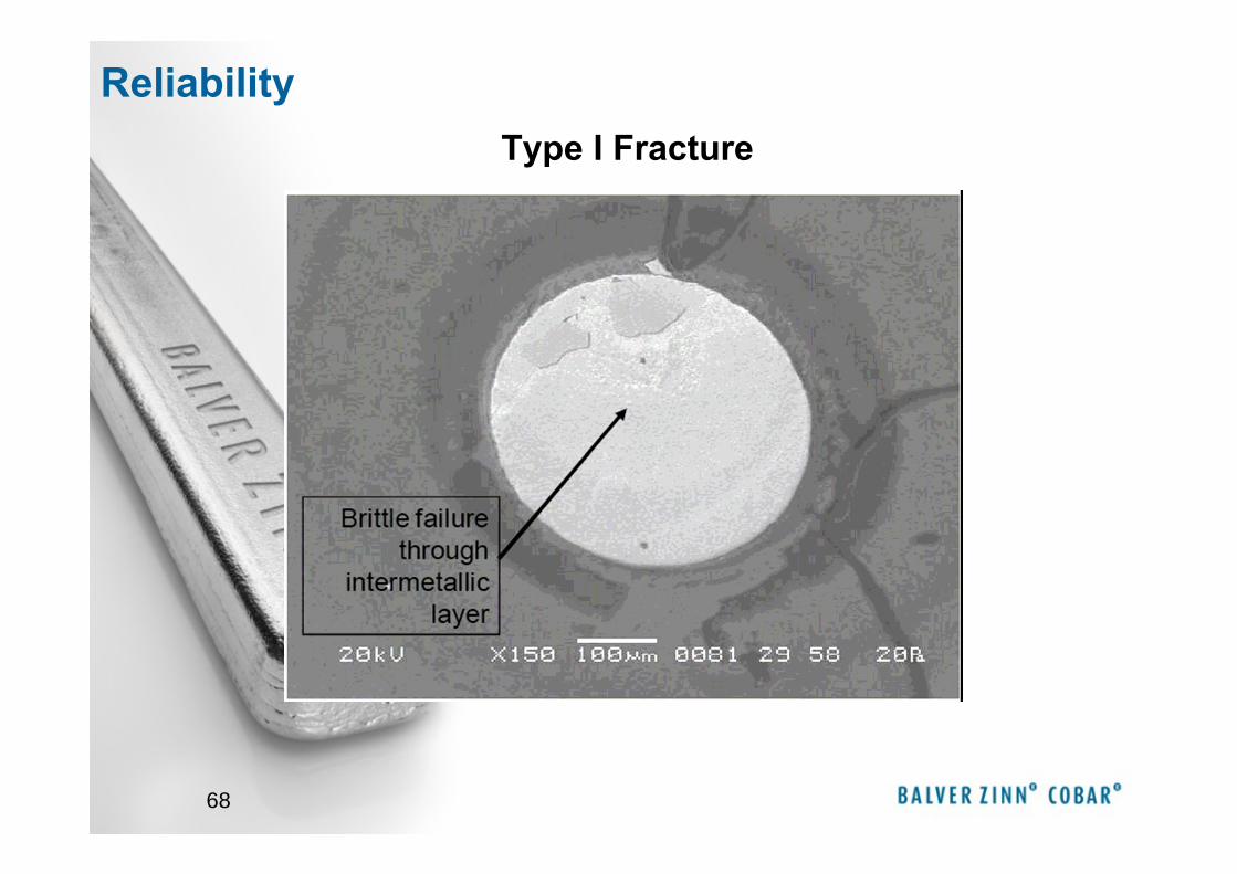
68
Type I Fracture
Reliability
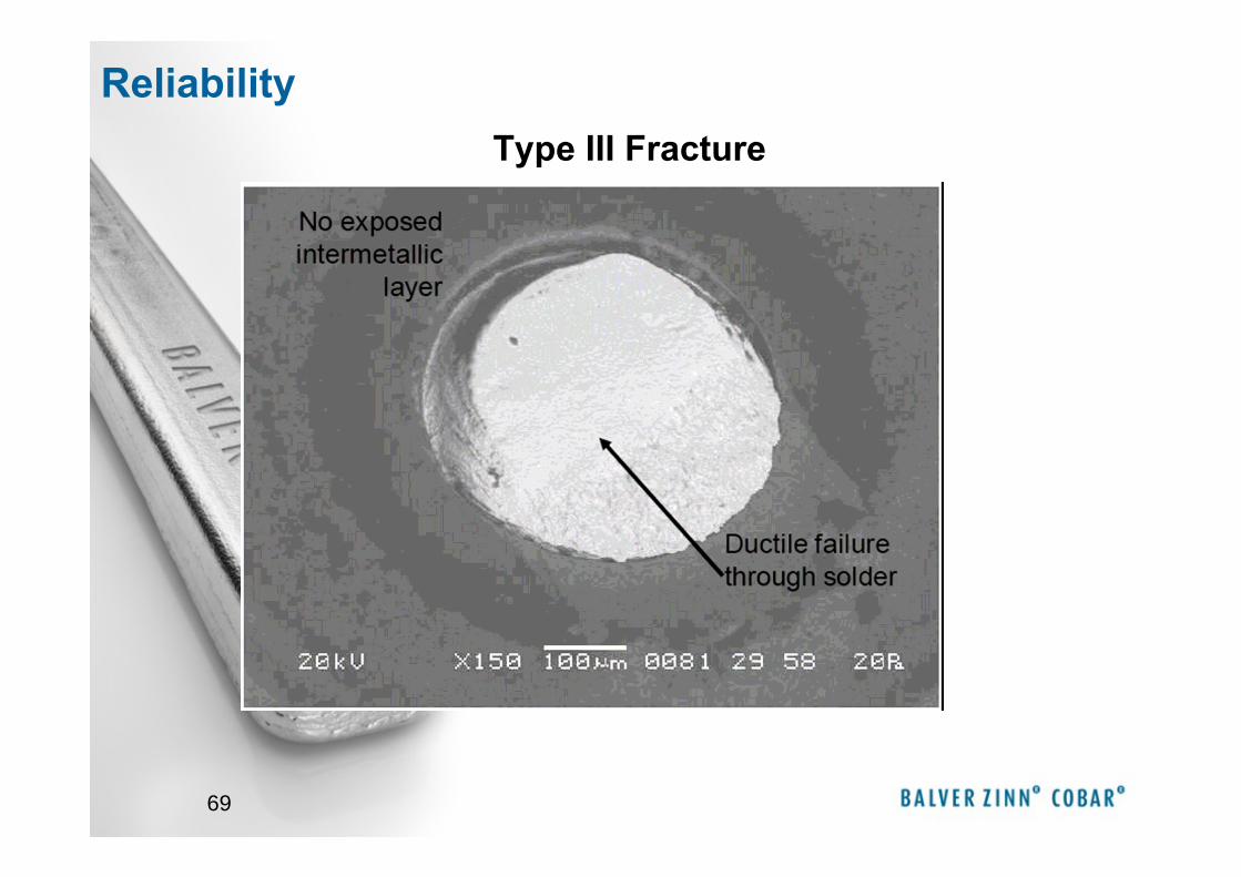
69
Type III Fracture
Reliability
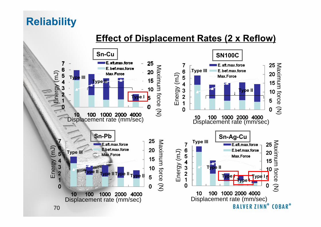
70
Sn-CuE
nerg
y (m
J)
Displacement rate (mm/sec)
Maxim
um force (N
)
SN100C
Displacement rate (mm/sec)
Ene
rgy
(mJ)
Maxim
um force (N
)
Type III
Type II
Sn-Pb
Ene
rgy
(mJ)
Displacement rate (mm/sec)
Maxim
um force (N
)
Sn-Ag-Cu
Displacement rate (mm/sec)
Ene
rgy
(mJ)
Maxim
um force (N
)
Type III
Type II
Type I
Type III
Type III
Type IIType IIType IIType II Type I
Type I
Type II
Type I
Effect of Displacement Rates (2 x Reflow)
Type III
Reliability
71
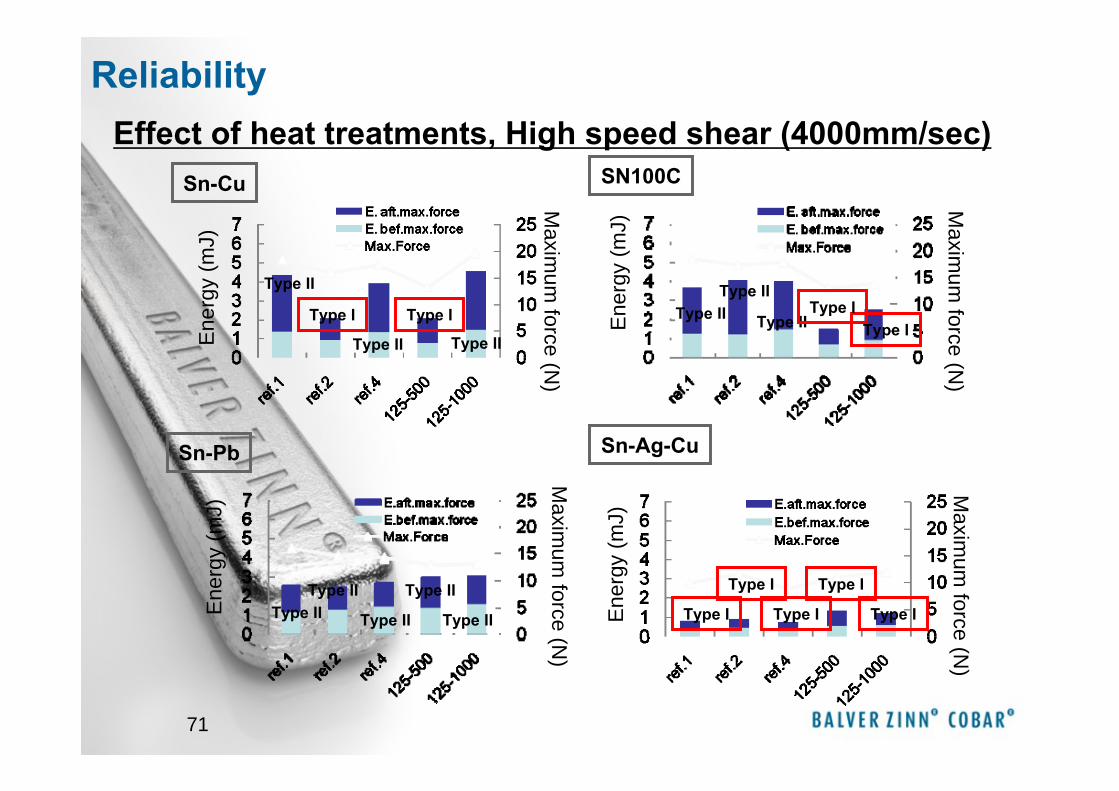
Sn-Cu
Sn-Pb
SN100C
Sn-Ag-Cu
Ene
rgy
(mJ)
Maxim
um force (N
)
Ene
rgy
(mJ)
Maxim
um force (N
)
Ene
rgy
(mJ)
Maxim
um force (N
)
Ene
rgy
(mJ)
Maxim
um force (N
)
Type II
Type II Type II
Type IType I Type II Type II
Type II
Type IType I
Type II Type II Type II
Type II Type IIType I
Type I
Type I
Type I
Type I
Effect of heat treatments, High speed shear (4000mm/sec)
Reliability
72
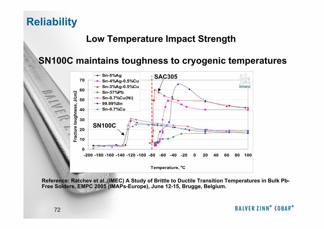
SN100C maintains toughness to cryogenic temperatures
72
0
10
20
30
40
50
60
70
-200 -180 -160 -140 -120 -100 -80 -60 -40 -20 0 20 40 60 80 100
Temperature, oC
Frac
ture
toug
hnes
s, J
/cm
2Sn-5%AgSn-4%Ag-0.5%CuSn-3%Ag-0.5%CuSn-37%PbSn-0.7%Cu(Ni)99.99%SnSn-0.7%Cu
Reference: Ratchev et al.,(IMEC) A Study of Brittle to Ductile Transition Temperatures in Bulk Pb-Free Solders, EMPC 2005 (IMAPs-Europe), June 12-15, Brugge, Belgium.
SAC305
SN100C
Low Temperature Impact Strength
Reliability
73
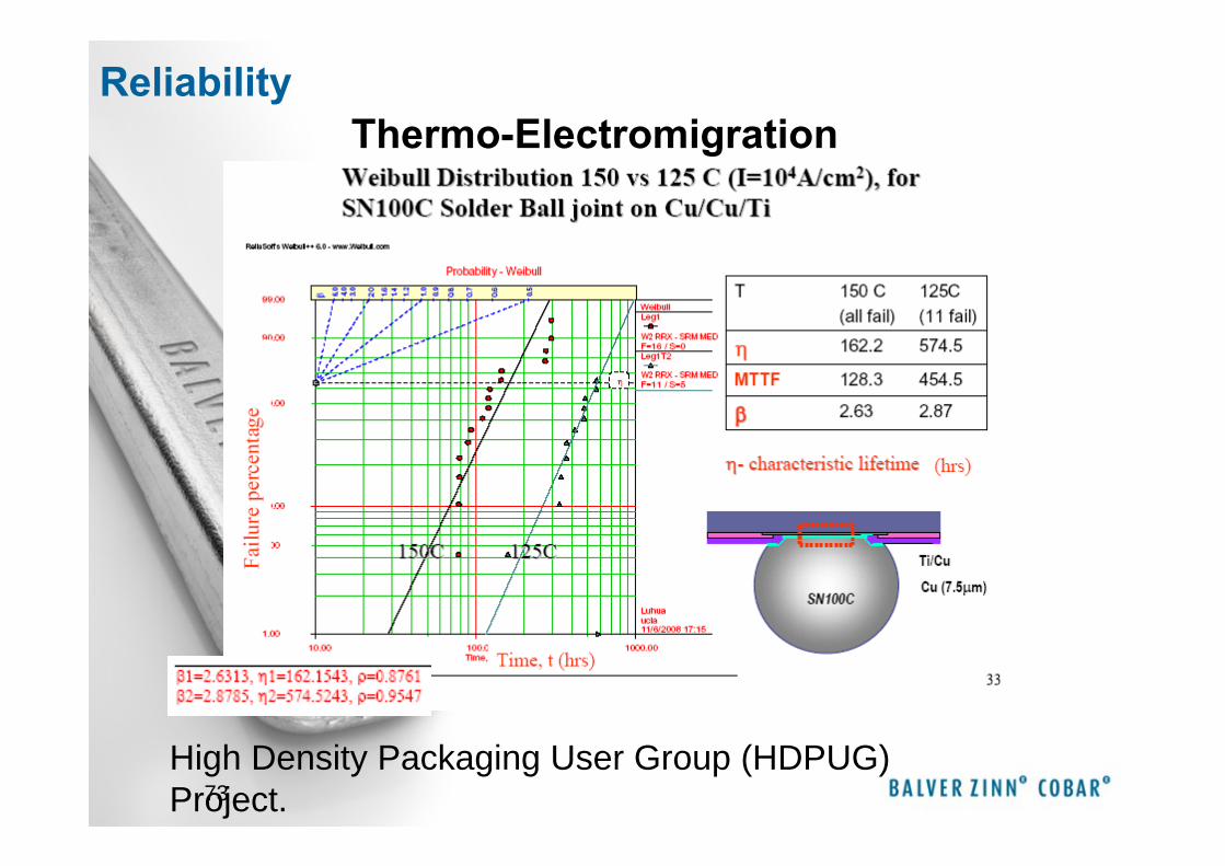
Thermo-Electromigration
High Density Packaging User Group (HDPUG) Project.
Reliability
74
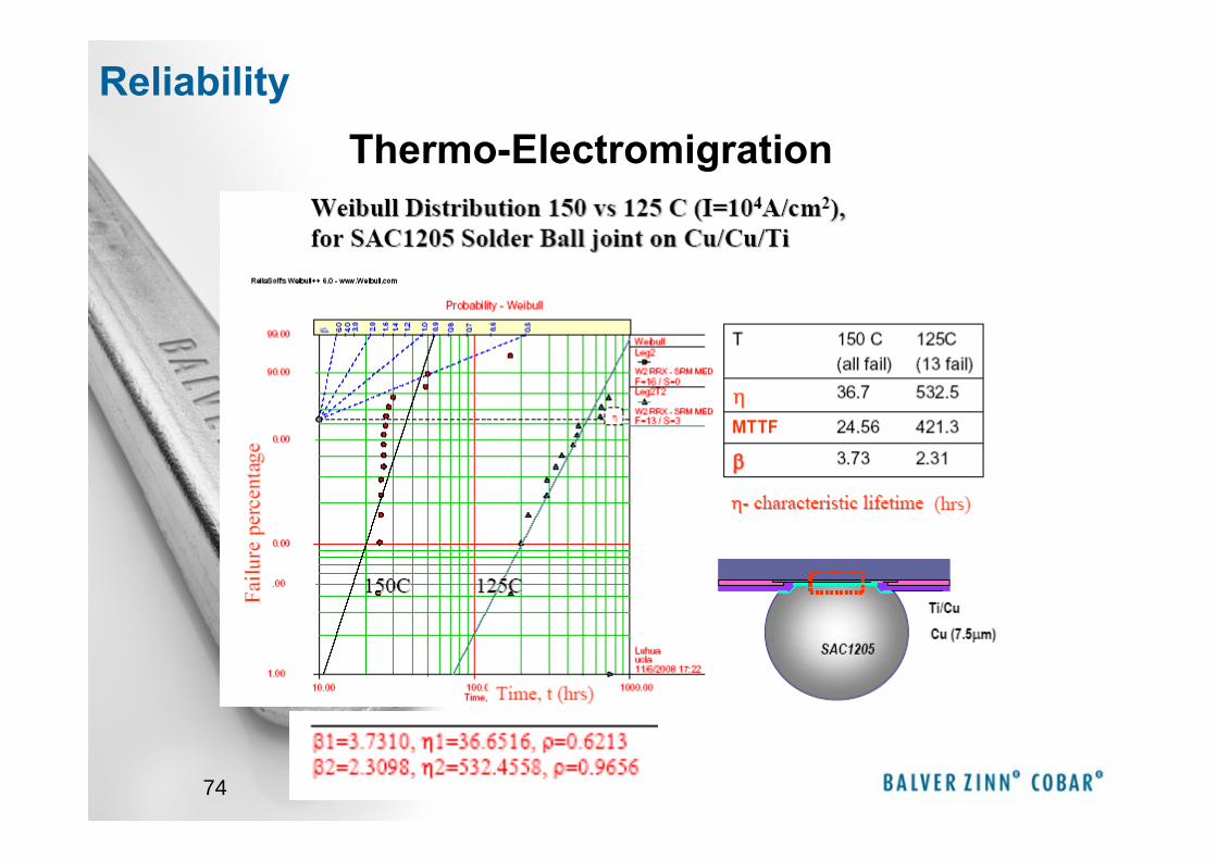
Thermo-ElectromigrationReliability

75
JESD22A121 –“Measuring Whisker Growth on Tin and Tin Alloy Surface Finishes”
Copper wire hot dip coated with the tested alloy was bent into U shape and tested according to:
• -40/+85°C 10 Inspect at 500 and 1000cycles No Whiskers!
No Whiskers!
Some 50μm whiskers in area of compressive stress on bend
~12mm
~25mm
Coating in Compression
Whiskers grow when there is compressive stress and conditions that
t
SN100C
• 60°C/87% RH Inspect at 1000, 2000, 3000 hours
• 30°C/60% RH Inspect at 1000, 2000, 3000 hours
Whisker SusceptibilityReliability

76
After an initial period of growth whiskers on SN100C do not grow further
Whiskers on SAC305 continue to grow…
… probably driven by ongoing corrosion
Whisker Length as a Function of Hours at 60C/87%RH
0
50
100150
200
1000 2000 3000
Hours
Whi
sker
Len
gth
(mic
rons
)
SN100CSAC305SnPb
Reliability
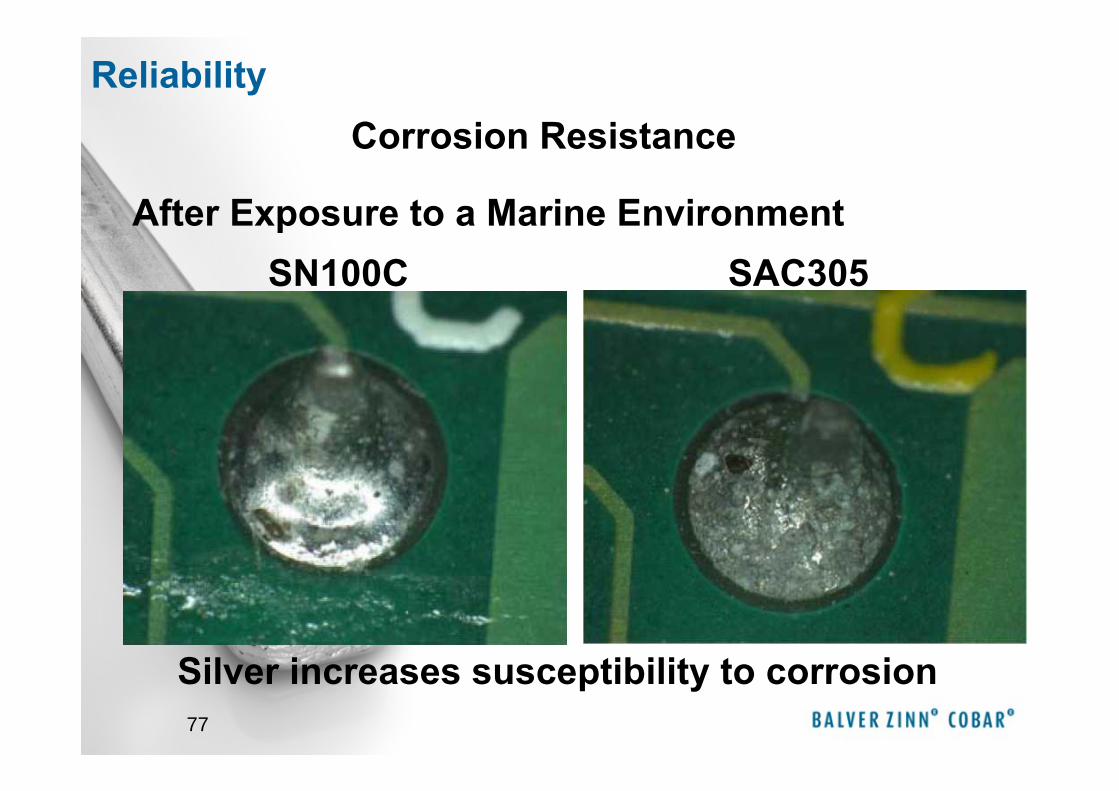
77
Corrosion Resistance
After Exposure to a Marine EnvironmentSN100C SAC305
Silver increases susceptibility to corrosion
Reliability
78
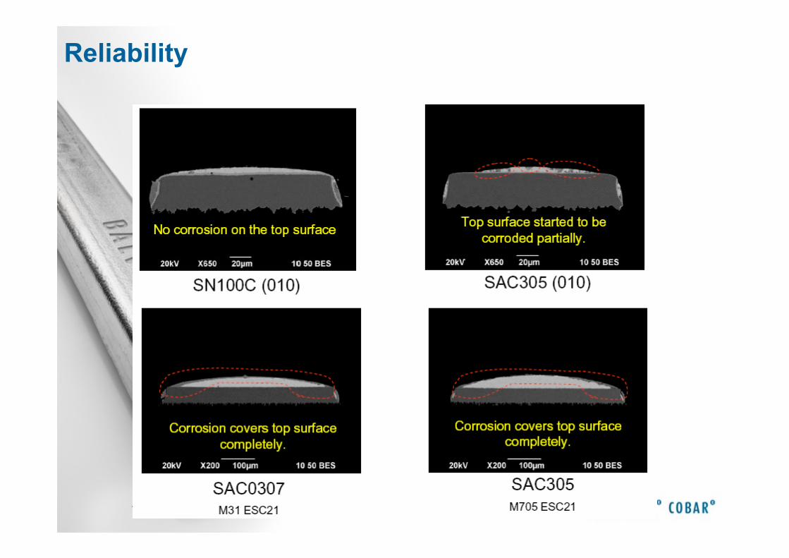
Reliability
79
• SN100C is a proven Pb-free solder with which can deliver high yield high reliability soldering for most printed circuit board assemblies on standard soldering equipment at peak assembly temperatures that do not compromised board and component integrity
• Successful soldering of thermally challenging assemblies can be achieved with equipment that has been designed to maximise heat transfer to achieve wetting temperature quickly without excessive overshoot.
Summary
80
Thank you for your Attention!