COMPLEXITIES IN FATIGUE OF ENGINEERING MATERIALS … · 539 BHANU SANKARA RAO : COMPLEXITIES IN...
41
Trans. Indian Inst. Met. Vol.57, No. 6, December 2004, pp. 537-577 GD BIRLA MEDAL LECTURE 2004 PREAMBLE I express my deep sense of gratitude to the Indian Institute of Metals for the great honour it has bestowed on me by conferring the G.D. Birla Gold Medal for the year 2004. It is a matter of pride to join the select band of very distinguished metallurgists of the country who have made outstanding research contributions to the field of Materials Science and Engineering. I feel extremely happy that my humble contributions in the field of materials science and engineering have been recognized by my peers by selecting me for the G.D. Birla Gold Medal Award. My research work started at Bhabha Atomic Research Centre, Bombay in 1974 on the development of copper base alloys for resistance welding electrodes by employing casting and powder metallurgical routes as a part of my M.Tech course in physical metallurgy at IIT Bombay. I have continued my research interest in powder metallurgy during my tenure as a Lecturer at Regional Engineering College, Warangal during 1975-77. Subsequently I have moved to Mechanical Metallurgy Group at Reactor Research Centre (RRC) (now Indira Gandhi Centre for Atomic Research IGCAR) Kalpakkam. In retrospect I feel that this was the most significant and fortunate decision I took in my career. Work in the area of mechanical metallurgy at Kalpakkam was initiated and nurtured for over 25 years by Dr. Placid Rodriguez whose personal example of dedication to work and emphasis on meaningful novelty and research have been an inspiration and beacon light to guide the progress in my research career. He has provided the umbrella under which, work in many areas including mechanical metallurgy flourished at Kalpakkam. He has been my principal mentor and supervisor of my Ph.D. research work. At Kalpakkam, I have been a member of a team that set up facilities for materials development and evaluation of mechanical properties. This gave me an opportunity to interact with Dr. S.L. Mannan who acted as a friend, philosopher and guide in the formative years of my research career. In all my endeavours at Kalpakkam he has remained as a valued co-researcher. I have developed a special interest in mechanical metallurgy as I could foresee the important contributions that are required in materials development and characterization of mechanical properties, for the development of Fast Breeder Reactor (FBR) Technology in India. We have established facilities for fatigue research at RRC during 1980 and to our surprise we found that there is a lack of consensus on several issues in low cycle fatigue and creep-fatigue interaction testing that has severely impaired the generation of meaningful data for the design of FBRs. We realized the need for standardization of testing methodology and undertook a serious campaign to assess the various factors responsible for intra and inter-laboratory variability in Low Cycle Fatigue (LCF) properties. In a short span of time we were able to provide a unified criterion for the determination of strain hardening exponent that serves as a guide in the selection of materials, crack initiation and failure life in laboratory specimens. These definitions have been universally accepted today. Subsequently we have laid a major emphasis on characterization of the effects of microstructure and various testing variables on phenomenological and micro mechanistic aspects on FBR structural materials including stainless steels, COMPLEXITIES IN FATIGUE OF ENGINEERING MATERIALS AT ELEVATED TEMPERATURES K. Bhanu Sankara Rao Mechanical Metallurgy Division Indira Gandhi Centre for Atomic Research, Kalpakkam 603 102 e-mail: [email protected] (Received 22 November 2004 ; in revised form 10 January 2005)
Transcript of COMPLEXITIES IN FATIGUE OF ENGINEERING MATERIALS … · 539 BHANU SANKARA RAO : COMPLEXITIES IN...

Trans. Indian Inst. Met.
Vol.57, No. 6, December 2004, pp. 537-577GD BIRLA MEDAL LECTURE 2004
PREAMBLE
I express my deep sense of gratitude to the IndianInstitute of Metals for the great honour it has bestowedon me by conferring the G.D. Birla Gold Medal forthe year 2004. It is a matter of pride to join theselect band of very distinguished metallurgists of thecountry who have made outstanding researchcontributions to the field of Materials Science andEngineering. I feel extremely happy that my humblecontributions in the field of materials science andengineering have been recognized by my peers byselecting me for the G.D. Birla Gold Medal Award.
My research work started at Bhabha Atomic ResearchCentre, Bombay in 1974 on the development ofcopper base alloys for resistance welding electrodesby employing casting and powder metallurgical routesas a part of my M.Tech course in physical metallurgyat IIT Bombay. I have continued my research interestin powder metallurgy during my tenure as a Lecturerat Regional Engineering College, Warangal during1975-77. Subsequently I have moved to MechanicalMetallurgy Group at Reactor Research Centre (RRC)(now Indira Gandhi Centre for Atomic ResearchIGCAR) Kalpakkam. In retrospect I feel that thiswas the most significant and fortunate decision I tookin my career. Work in the area of mechanicalmetallurgy at Kalpakkam was initiated and nurturedfor over 25 years by Dr. Placid Rodriguez whosepersonal example of dedication to work and emphasison meaningful novelty and research have been aninspiration and beacon light to guide the progress inmy research career. He has provided the umbrellaunder which, work in many areas includingmechanical metallurgy flourished at Kalpakkam. He
has been my principal mentor and supervisor of myPh.D. research work.
At Kalpakkam, I have been a member of a team thatset up facilities for materials development andevaluation of mechanical properties. This gave mean opportunity to interact with Dr. S.L. Mannanwho acted as a friend, philosopher and guide in theformative years of my research career. In all myendeavours at Kalpakkam he has remained as a valuedco-researcher. I have developed a special interest inmechanical metallurgy as I could foresee the importantcontributions that are required in materialsdevelopment and characterization of mechanicalproperties, for the development of Fast BreederReactor (FBR) Technology in India. We haveestablished facilities for fatigue research at RRCduring 1980 and to our surprise we found that thereis a lack of consensus on several issues in low cyclefatigue and creep-fatigue interaction testing that hasseverely impaired the generation of meaningful datafor the design of FBRs. We realized the need forstandardization of testing methodology and undertooka serious campaign to assess the various factorsresponsible for intra and inter-laboratory variabilityin Low Cycle Fatigue (LCF) properties. In a shortspan of time we were able to provide a unifiedcriterion for the determination of strain hardeningexponent that serves as a guide in the selection ofmaterials, crack initiation and failure life in laboratoryspecimens. These definitions have been universallyaccepted today. Subsequently we have laid a majoremphasis on characterization of the effects ofmicrostructure and various testing variables onphenomenological and micro mechanistic aspects onFBR structural materials including stainless steels,
COMPLEXITIES IN FATIGUE OF ENGINEERINGMATERIALS AT ELEVATED TEMPERATURES
K. Bhanu Sankara RaoMechanical Metallurgy Division
Indira Gandhi Centre for Atomic Research, Kalpakkam 603 102e-mail: [email protected]
(Received 22 November 2004 ; in revised form 10 January 2005)

538
TRANS. INDIAN INST. MET., VOL. 57, NO. 6, DECEMBER 2004
ferritic steels, superalloys and their weldments. Thisenabled us to develop a deeper understanding of thevarious time and temperature dependent phenomenainfluencing the LCF properties and facilitated theselection of materials, appropriate life predictiontechniques and fix limits to their extrapolation. Theinformation generated has also been found useful informulation of the constitutive equations and designrules for FBR materials and their weldments. Wealso have the distinction of discovering uniform matrixcavitation in high temperature fatigue, establishingvarious manifestations of dynamic strain ageing infatigue and defining the procedures for determinationof various time and temperature dependent processesand their synergistic interactions. Over the years Ihave been engaged in research activities pertaining tomaterials development, tensile deformation andfracture, creep, low cycle fatigue, creep-fatigueinteraction, thermomechanical fatigue, structure-property correlations, life assessment and prediction.Deeper understanding of the above mentioned subjectsnecessitated extended discussions with various expertsat IGCAR, Kalpakkam. I have benefited from themeaningful discussions that I had on the above subjectswith Dr. Baldev Raj since the beginning of myresearch career. This in retrospect has proved to bea boon that we have entered into a new territory ofresearch comprising of correlation betweenmicrostructure, mechanical properties and non-destructive testing parameters. In the last decade wewere able to establish correlations between variousNDT parameters and cyclic softening, hardening,fatigue crack initiation and propagation, creepdeformation and fracture, development ofsubstructure, precipitation of various phases and theirgrowth in stainless steels, ferritic steels andsuperalloys. These studies have been foundindispensable in structural integrity assessment andlife assessment of the power plant components.Recently we were able to contribute an invited reviewpaper on “Assessment of Microstructures andMechanical Behaviour of Metallic Materials throughNon-Destructive Characterization” to InternationalMaterials Reviews. Dr. Baldev Raj , Director,IGCAR, Kalpakkam who himself being adistinguished Scientist and metallurgist of high reputeset stiff standards for all of us to emulate and providedstimulatory environment, encouragement and support.Mechanical Metallurgy Division at IGCAR,
Kalpakkam today has been recognized both nationallyand internationally for many original contributionsin the area of high temperature deformation andfracture of materials required in support of the FBRprogramme.
I have been deputed to Kernforschungsanlage, Juelich,Germany under Indo-German Bilateral agreement in1984 for a period of 16 months. This gave me anopportunity to work on time dependent fatigue andcreep-fatigue interaction of high temperature gascooled reactor materials under the able guidance ofDr. H. Schuster and Prof. H. Nickel. These studieshave provided mechanistic understanding and muchneeded information on the design rules of heatexchanger components. In 1993, I have been awardedNational Research Council of USA fellowship to workas a Guest Scientist and Resident Research Associateat NASA-Lewis Research Center, Cleveland for aperiod of two years. NASA-Lewis Research Centerhas been a world leader in high temperature fatiguesince the discovery of Manson-Coffin relationship in1954 and this fellowship provided me a uniqueopportunity to work on aerospace materials under thestewardship of Dr. G.R. Halford. My contributionsat NASA-Lewis Research Center resulted inunderstanding of complexities in the fatigue behaviourof superalloys, intermetallics and fiber reinforcedmetal-matrix composites.
In my presentation of the G.D. Birla Gold MedalLecture today, I will not be able to do justice to allthe areas of my research work that culminated in thepublication of more than 250 research papers. I havetherefore chosen to review certain aspects of my workwith emphasis on high temperature fatigue whichresulted in advancement of knowledge base on severalstainless steels and their weldments, superalloys,nickel aluminides and SiC continuous fiber reinforcedmetal matrix composite.
1. INTRODUCTION
Low cycle fatigue is an important consideration inthe design and operation of high temperature systemsthat are subjected to repeated thermal stresses as aresult of temperature gradients which occur on heatingand cooling during start-up and shut-downs or duringthe thermal transients1-3. On-load periods at elevatedtemperatures introduce time-dependent effects, most

539
BHANU SANKARA RAO : COMPLEXITIES IN FATIGUE OF ENGINEERING MATERIALS AT ELEVATEDTEMPERATURES
importantly creep among many other effects. Thesystems that can undergo thermal transients includenuclear pressure vessels, steam turbines, aircraft gasturbines, heat exchangers and fuel elements,automobile parts and power plant components etc. Inorder to represent the component behaviour in alaboratory test, the thermal strains are replaced bymechanical strain and controlled under isothermalconditions. The slow start-up and shut-down cycle isreplaced by a symmerrtrical and a continuous cycleof equal strain rates in tension and compression (Fig.1), with a hold period at a constant peak strain tosimulate the on-load period, i.e., creep-fatigueinteraction. Slow-fast and fast-slow strain-timewaveforms represent another category used to evaluatecreep fatigue interaction effects.
Thermal stresses within a component are often highlylocalized and deformation constrained by surroundingmaterial and thus generally result in strain controlleddeformations. LCF failures represent a predominantfailure mode, necessitating significant considerationin the design and life analysis of aforementionedcomponents. Towards the goal of developing anaccurate and sufficiently general life analysis tool, itis essential that the incorporated material behaviourmodel be physically based, representing featuresassociated with the dominant fatigue deformation anddamage mechanisms. This ultimately requires acomprehensive understanding of both the macroscopiccyclic deformation behaviour under the appropriateloading conditions, and the micromechanisms whichinfluence such behaviours, as revealed in thedeformation substructure and failure modes. Further,this understanding must include not only the behaviourat the maximum operating temperatures, but also thebehaviour at the lower temperatures encounteredduring transients. This is obiviously a challengingtask, given that high temperature material behaviouris often a function of the synergestic interactions ofvarious time and temperature dependent variables/phenomena, such as slip mode, oxidation damage,creep damage, dynamic strain ageing, dynamicprecipitation and phase instabilities, inelasticdeformation, deformation ratchetting, mean stress3-8,and many others. Depending on the type of alloy andthe metallurgical condition of the material, the effectsof these time-dependent processes on cyclic stressresponse may be considerable and, in the worst case
may reduce cyclic life by orders of magnitude ascompared to room temperature value. By studyingthe deformation substructure and damage behaviouras a function of temperature, it is possible to obtaindeeper insight into various time-dependent processes,their interactions, and other factors deteriorating thefatigue life at elevated temperatures. Such studies areof immense importance for developing constitutiveequations in different temperature regimes. Thegeneration of such information would also facilitatethe development and selection of appropriatepredictive methods and fix limits to theirextrapolation.
In addition to creep and fatigue loading, operatingconditions in reactor vessels and aero engines involvethermal transients with mechanical strain cycles9-11.This thermomechanical fatigue (TMF) loading oftengoverns the lifetime of many high-temperaturecomponents. However, TMF tests are seldom carriedout for generating data pertaining to material selectionand qualification, primarily on account of the hugeexperimental efforts involved and the large numberof test parameters that must be set for TMF testingin contrast to the conventional isothermal fatiguetesting. Consequently, isothermal LCF tests performedat the maximum temperature of the expected TMFloading cycle are generally used as a basis for TMFlifetime prediction. This procedure, however, couldinvolve considerable uncertainties especially if thedevelopment of the cyclic stress-strain response andthe evolution of microstructure and micromechanismsof crack initiation and propagation are different fromthose under isothermal conditions. Often, the typeand rate of occurrence of time and temperaturedependent damage mechanisms and their interactionsleading to failure in TMF conditions may be differentthan under isothermal LCF conditions. Therefore,the evaluation of TMF behaviour of materials usedin critical applications has become indispensable. Inan effort to examine the phenomenological effects ofvarious testing variables and characterize themicromechanisms active during high temperatureloadings, detailed investigations have been performedover the years under isothermal, creep-fatigue andTMF loading conditions on materials of interest toFBRs, gas cooled reactors and aero engines. Some ofthe salient findings are presented in this paper.

540
TRANS. INDIAN INST. MET., VOL. 57, NO. 6, DECEMBER 2004
2. EFFECTS OF MICROSTRUCTUREON LOW CYCLE FATIGUEBEHAVIOUR
The cyclic deformation and fracture of austeniticstainless steels engineered for high temperatureapplications depend critically on the initialmicrostructure [grain size (GS), prior cold work(PCW) and thermal ageing (TA)] and slip mode,both of which in turn depending on temperature,govern the cyclic stress response and the mode ofcrack initiation and propagation. In FBRs, for the
core components, cold worked austenitic stainlesssteels are often recommended to reduce radiationinduced void swelling. During fabrication of thesheets and plates into vessels, tanks, pipings, heatexchangers, etc., cold work may be introducedunintentionally and its influence on elevatedtemperature behaviour is to be accounted in thedesign.
2.1 Grain Size Effects on Strain Controlled LCFBehaviour of Type 304 Stainless Steel
The GS dependence of LCF life of a meta stabletype 304 stainless steel in the range 300 to 1023 Khas been investigated in detail2,6,12,13. LCF life wasfound to be strongly dependent on GS, temperatureand strain amplitude employed in the testing (Figs.2a & b). In general, fine GS exhibited better fatigueresistance, an exception to this being the results at300 K at high strain amplitudes where increasing GS
Fig. 1: Typical waveforms for strain controlled fatigue testingFig. 2: Influence of grain size on LCF life at (a) 300 K and
(b) 923 K2
(a)
(b)

541
BHANU SANKARA RAO : COMPLEXITIES IN FATIGUE OF ENGINEERING MATERIALS AT ELEVATEDTEMPERATURES
showed a tendency for improved fatigue resistance.The improved life at 300 K in coarse GS at highstrain amplitudes resulted from the beneficial effectsarising from the deformation induced transformationof austenite to ’-martensite at the crack tip.Martensite formed around the crack tip absorbs thestrain energy and suppress the crack propagation byproducing residual compressive stresses14,15. Nomartensite could be found in fine GS material at thecrack tip.
The beneficial effect of fine GS seems to result fromboth the extended crack initiation and propagationstages. Since the GS governs the slip length16, asmall grain size can be expected to develop smallersteps at the surface, which would render the formationof intrusions and extrusions more difficult. Becauseof the greater constraints to slip in finer GS materiala large number of slip systems are required to operate,
to generate the required strain. The constraint andcorresponding reduction in slip per band make thecrack initiation event a more difficult process in finegrained material than in coarse grained alloy. Theimproved crack propagation resistance with decreasingGS in alloys deforming by planar slip has beenascribed to the fact that grain boundaries act as thenatural barriers for transgranular crack propagation17
causing the crack front to be held back andnecessitating the crack reinitiation event to occur ineach new grain.
In all the grain sizes, life decreased drastically withincreasing temperature upto 923 K (Fig. 3) Thetemperature effect on the reduction in life at elevatedtemperatures has generally been attributed to theincreased inelastic strain in a given cycle, creepdamage, and oxidation. The temperature dependenceof inelastic strain in all the grain size showed a
Fig. 3:Effect of temperature on fatigue life at different strain ranges for (a) fine grain and (b) medium Grain sized material.
(a) (b)
Fig. 4: (a) Ductile striations on the fracture surface of the sample tested at 300 K and (b) brittle striations at 823 K at atotal strain amplitude of +0.6%2.
(a) (b)

542
TRANS. INDIAN INST. MET., VOL. 57, NO. 6, DECEMBER 2004
minimum at 823 K, and still a drastic reduction inlife was observed due to DSA effects. The alloydisplayed crack initiation in persistent slip bands,followed by stage I and stage II crack propagation,respectively characterized by the occurrence ofrelatively featureless region and well defined striationsupto 823K. At 823K, fine GS revealed ductilestriations while medium and coarse grain sizesexhibited brittle striations (Figs. 4a & b). Brittlestriations are the characteristic signatures of DSAprocess in fatigue. At 923 K, irrespective of GS, theoxidation effects became dominant. In fine GS, theeffect of oxidation seems to result from the oxidationenhanced, stage I transgranular crack initiation andstage II transgranular crack propagation. The effectof oxidation on stage I cracking in planar slip alloyscould be attributed to the slip step passivationmechanism, which by reducing the degree of slipreversibility enhances crack nucleation at slip steps.Oxide-enhanced transgranular crack growth resultsfrom the repeated formation of an oxide layer at thecrack tip, its rupture, and exposure of the freshmaterial to the environment in each cycle. Oxidationat the crack tip would render a thin layer of materialmore brittle and so would assist crack propagation.In the medium and coarse grain sizes, build up ofshear stress concentrations at the grain boundary triplepoints located at and near surface regions promotedoxidation induced intergranular cracking by grainboundary notching (Fig. 5a). The absorption andinward diffusion of oxygen atoms down the grainboundaries cause reduction in surface energy and,presumably, in the cohesive strength across the grainboundary. Occasionally, intergranular cavities havebeen noticed in all the grain sizes at 923 K (Fig. 5b).It is proposed that the cavities occur by the interaction
of oxygen with grain boundary carbides. In spite ofthe presence of these cavities, fine GS did not undergointergranular cracking. This can be related to theinfluence of GS on slip character. In medium andcoarse grain sizes, planar slip bands cause edgedislocations to pile-up at grain boundaries, whichpromote stress concentrations. The cumulative actionof stress concentration arising from slip bandimpingement leads to the unzipping of cavitatedmaterial. The ability of fine GS to spread thedeformation inhibits the development of long pile-ups and associated stress concentration at the grainboundary, hence decohesion of the cavitated grainboundaries has not been achieved. Fatigue lives ofvarious stainless steels decreased due to the increasedtendency to form wedge cracks and cavities withincreasing GS2,18,19. Grain size effects were foundmore pronounced under creep-fatigue interactionloading conditions18,19.
2.2 Effects of Prior Cold Work on LCF Behaviourof Type 304 Stainless Steel
In the LCF tests conducted on 304SS employing totalaxial strain as the control parameter, cyclicdeformation and lives were found to be a strongfunction of PCW. In general, SA material exhibitedbetter total strain fatigue resistance than the materialin 10, 20 and 30% PCW conditions in the range300-1023 K, except for strain amplitudes less than0.30% at 300 K2,20-22. At 823 K, LCF resistancedecreased with increasing PCW (Fig. 6a). At 923 K,10%PCW exhibited the lowest life; higher PCWlevels showed recovery in life (Fig. 6b). At 823 K,the continuous decrease in life with increasing PCWhas been found to have correlation with rank order
Fig. 5: (a) oxidation assisted intergranular cracking at grain boundary triple points and (b) Cavities on grain boundariesresulted by the interaction of oxygen with carbides2.
(a) (b)

543
BHANU SANKARA RAO : COMPLEXITIES IN FATIGUE OF ENGINEERING MATERIALS AT ELEVATEDTEMPERATURES
Fig. 6: Influence of prior cold work on fatigue life at (a) 823 K and (b) 923 K and substructures developed during LCFtesting at (c) 823 K and (d) 923 K 2,20
amplitudes has also been observed in 20% cold worked316L(N) stainless steel and titanium modifiedaustenitic stainless steel (Alloy D9)23-25. The SA and10% PCW 304SS displayed drastic reduction in lifewith decreasing frequency at 923 K2,27. Timedependent damage mechanisms namely inelasticdeformation, DSA, oxidation, intergranular creepdamage and uniform matrix cavitation have beenfound responsible for life degradation, however, theirrelative effects depended on initial microstructure andfrequency. The exponent in plastic strain-liferelationships showed more negative values in SAcondition due to DSA effects while in the PCW alloymore positive values prevailed with decreasingfrequency due to the beneficial effects associated withsubstructural recovery and intergranularprecipitation.
of monotonic ductility, which decreased continuouslywith increasing PCW. The improved life of 20 and30% PCW materials at 923 K had its origin in straininduced precipitation and prevailing deformationmodes. The 10% PCW alloy displayed intergranularcracking while 20 and 30% PCW conditions exhibitedpredominantly transgranular crack propagation. At923 K, 10% PCW condition showed planar slip(Fig. 6c) while in 20 and 30% conditions thesubstructure primarily comprised cells and subgrains(Fig. 6d). Relatively large amounts intergranularcarbides precipitated at higher PCW levels enhancedthe resistance to grain boundary sliding and reducedthe incidence of intergranular cracking. The dynamicrecovery in 20 and 30% PCW conditions appears tolead to enhanced ductility with an associated increasein life. At 923 K, increase in LCF life at low strain
(a) (b)
(c) (d)

544
TRANS. INDIAN INST. MET., VOL. 57, NO. 6, DECEMBER 2004
Studies on Alloy D9 at 923 K clearly indicated thedetrimental effect of cold work on creep-fatigueinteraction resistance. Life decreased with increasingtensile hold time for both the alloy with Ti/C ratiosof 4 and 8. Creep-fatigue interaction effects weremore pronounced at higher Ti/C ratio due to profuseprecipitation of TiC in matrix which promoted grainboundary weakening leading to intergranularfailure.
2.3 Uniform Matrix Cavitation in HighTemperature Fatigue
Studies on effects of microstructure on type 304 SS(presented in section 2.1 and 2.2) have led to thediscovery of uniform matrix cavitation in straincontrolled fatigue at elevated temperatures1,2. Thesevoids were distributed uniformly within the grains
without showing any special preference toheterogeneous nucleation sites like twin boundaries,slip bands, sub-grain boundaries or matrix carbides(Fig.7a)29-32. The existence of void free zones in thevicinity of grain boundaries have indicated that matrixvoids nucleate without having any association withmigrating grain boundaries (Fig. 7b). It wasestablished that quenching the alloy from a very highsolutionising temperature (to produce coarse GS) orprior cold working of the material is a necessary pre-requisite to cause homogeneous cavitation in the graininteriors during LCF deformation. The average voiddiameter (D) decreased with decreasing frequency(Fig. 7c) despite an order of magnitude increase inthe total time available for nucleation and growth ofvoids. D increased with increase in strain amplitude(Fig. 7d) despite a considerable decrease in the timeto failure at larger strain amplitudes.
Fig. 7: (a) Uniform matrix cavitation during LCF, (b) Void free zone adjoining to grain boundary, (c) Variation of voiddiameter (D) with time to failure (tf) for 10% cold work condition at 923 K and (d) Effect of strain amplitude onvoid diameter for 304 SS tested at 0.1 Hz at 923 K with two different PCW levels2
(a) (b)
(c) (d)

545
BHANU SANKARA RAO : COMPLEXITIES IN FATIGUE OF ENGINEERING MATERIALS AT ELEVATEDTEMPERATURES
D has been found to increase with PCW. It has beenproposed that cyclic deformation under favorableconditions generate large number of matrix voidsand D is controlled by production of excess latticevacancies (higher at higher strain amplitudes and highfrequencies) and by their probability of arrival at the“void embryo” rather than the time available forgrowth. Interrupted tests revealed an incubation periodfor the nucleation of matrix voids. During this periodthe cumulative accumulation of vacancies generatedduring PCW and early cyclic deformation build upto a level high enough to cause direct condensationon effective nucleation sites such as dislocation loops.There was no significant increase in the size of voidsbetween 20% and end of life, whereas the numberdensity increased substantially. The development ofintergranular creep cavities, their subsequent growthand linkage which lead to intergranular fracture havebeen well established. The interaction of propagatingfatigue crack with intergranular cavities leads to creep-fatigue interaction failures. Uniform matrix cavitationis now considered as a possible damage mode infatigue.
2.4 Effects of Prior Microstructure on LCFDeformation and Fracture of SuperalloysNimonic PE 16 and Inconel 718
The cyclic deformation and fracture behaviour ofNimonic PE-16 superalloy has been assessed in variousmicrostructural conditions and micromechanismsinfluencing the fatigue behaviour have been
identified33-35. Three different microstructuresemployed for LCF testing include : (A) A fine grainstructure free from carbides and , (B) microstructurewith intra and intergranular M23C6 and uniformdistribution of spherical and peak aged of 18 nmdiameter, and (C) microstructure with predominantlyintergranular MC and overaged of 35 nm diameter.Microstructures B & C were produced through doubleageing treatments and were shown to have a goodcombination of tensile strength and ductility36-38.Alloy A exhibited higher plastic strain fatigueresistance than B and C36. The peak aged alloy Brevealed a non-ideal plastic strain fatigue responsewith a discontinuity in the strain-life plots (Fig. 8a);the samples cycled at lower strain amplitudes exhibitedmuch shorter lives than would be predicted byextrapolation from the high plastic strain amplitudeportion of the plot. Alloy B also exhibited two stagesin its half-life cyclic stress-strain curve (Fig. 8b).The fatigue life and fracture behaviour have beenfound to depend on the nature of slip, distribution of
and intergranular carbides. Alloy A in which thedeformation occurred by planar slip (Fig. 9a) exhibitedbetter fatigue resistance while the microstructure Cin which particles were bypassed predominantlyby Orowan looping mechanism displayed the least(Fig. 9b). The beneficial effects of planar slip onlife results from the slip reversibility which retardsthe transgranular crack initiation and propagation.Since bypassing of particles by Orowan mechanismrequires cross slip and loop formation, slip was notreversible to the same extent as in the cutting process
(a) (b)
Fig. 8: (a) Coffin-Manson plots and (b) Cyclic stress-strain curves of Alloy A, B & C at 923 K33,34
546
TRANS. INDIAN INST. MET., VOL. 57, NO. 6, DECEMBER 2004
and promotes accelerated propagation of fatiguecracks. Alloy C exhibited pronounced transgranularcleavage fracture in addition to some intergranularcracking (Fig. 10a). The cleavage fracture wasassociated with widely spaced slip bands in whichchannelization of dislocation activity has occurred(Fig 10b). The channelization of deformation leadsto dislocation pile-ups at the grain boundaries, causingstress concentration and intergranular decohesion ofthe carbides. The discontinuity in strain-life curvesof alloy B resulted from the differences in the degreeof homogeneity of deformation and fracture modesbetween low and high strain amplitudes. In alloy B,high strain amplitudes caused homogeneousdeformation and transgranular fracture whileconcentrated deformation in slip bands and mixedtrans plus intergranular mode of fracture prevailed atlow strains. The beneficial effect of planar slip waseclipsed under the double aged conditions where the
initial and evolving microstructure contained shearable precipitates, which promoted strain localization.
The deformation mechanisms and fatigue behaviourof double aged and pre-strained Inconel 718 superalloywere investigated at room temperature39,40. Theprestrains investigated simulate those imposed onmaterials during proof testing, accidental overloadand autofrettage. The alloy softened after a smallamount of hardening during the initial cycles (Figs.11a& b). At a strain range of 2%, monotonic tensilestraining did not have a significant effect on thesubsequent fatigue life. At lower strain range, thefatigue life of 10% pre-strained alloy was lower bynearly factor of five. Dislocation pairs observed inthe slip bands indicated that ordered precipitateswere sheared during deformation process (Fig. 12a).Cyclic softening was attributed to the continuous“mechanical scrambling” of precipitates by
(a) (b)
Fig. 9: (a) Planar dislocation arrangement in Alloy A at a strain amplitude of +0.4% and (b) Orowan looping mechanismin Alloy C at a strain amplitude of +1.0%34
(a) (b)
Fig. 10: (a) Facetted fracture appearance and (b) Superdislocation pairs in Alloy C at 923 K34
0.3 m

547
BHANU SANKARA RAO : COMPLEXITIES IN FATIGUE OF ENGINEERING MATERIALS AT ELEVATEDTEMPERATURES
dislocations in deformation bands, which eventuallyled to the formation of precipitation-free deformationbands (Fig. 12b). In specimens that weremonotonically strained in tension followed by fatiguetesting, deformation during the fatigue part of thetest occurred mostly along the deformation bandsactivated during the monotonic tensile strain.
3. EFFECTS OF DYNAMIC STRAINAGEING ON LCF BEHAVIOUR OFSTAINLESS STEELS
Table 1CYCLIC STRESS AND CYCLIC PLASTIC STRAIN
VALUES FROM EXPLORATORY STRAIN CONTROLLEDLCF TESTS2
Total Tempera- Stress Amplitude PlasticStrain ture (MPa) Strain Range (K) First Satura- Range
Cycle tion (%)
0.80 673 141 248 0.469
0.80 773 143 270 0.460
0.80 823 173 278 0.453
0.80 873 160 228 0.498
0.80 923 159 224 0.523
In the last two decades, considerable research effortshave been devoted to characterize the effects ofDynamic Strain Ageing (DSA) on LCF behaviour ofaustenitic stainless steels 304, 304L(N), 316L(N),Alloy D9, ferritic steels 2.25Cr-1Mo, 9Cr-1Mo,Mod. 9Cr-1Mo and superalloys Nimonic PE-16 andInconel 718 at IGCAR, Kalpakkam. The temperaturerange of application of these alloys encompass thedomain of occurrence of DSA. The early investigationson type 304 SS provided answers to several probingquestions. The characteristics of DSA in 304 SS duringLCF were evaluated as a function of grain size (75,310 and 700 m), temperature (300-923K), frequencyof cycling (0.0005-1.0 Hz) and strain range (0.5-3.0%)2,41. Through exploratory LCF tests, the peakDSA temperature was established as 823K. At 823K,DSA was manifested as a peak in the tensile saturationstress, a minimum in the plastic strain generated inthe cycle (Table 1), and increased cyclic hardeningrate. These features were found to be analogous tothe behaviour in monotonic tension tests where apeak in flow stress, minimum in tensile ductility andincreased work hardening rate were observed. Overthe DSA temperature range serrations were seen inthe plastic portions of stress-strain hysteresis loops;the type and magnitude of serrations were found todepend on grain size, applied strain amplitude, testtemperature and frequency of cycling. The criticaltemperature for the onset of serrations was established
(a) (b)
Fig. 11: Evaluation of cyclic stress range in a fully reversed fatigue test (a) with no pre-strain and (b) with pre-strain39,40

548
TRANS. INDIAN INST. MET., VOL. 57, NO. 6, DECEMBER 2004
(a) (b)
Fig. 12: (a) Slip band, dislocation pairs and pile-up at a grain boundary t = 0.8% and (b) Deformation bands devoid ofprecipitates39,40
(a) (b)
Fig. 13: (a) Normalised cyclic hardening curves illustrating the influence of strain rate 823 K for medium grain size material,strain amplitude +0.4% and (b) Coffin-Manson plots for fine grain size at 923 K for different frequencies2.
exhibited greatest tendency for brittle intergranulardecohesion2,6,43. The detrimental effect of DSA onLCF life has also been noticed in the studies conductedon stainless steels Alloy D944,45, 304L(N)46 and316L(N)47-50 and Nimonic PE-168 superalloy in therange 298-923K. The operation of DSA introducedcritical changes in the cyclic stress response anddislocation substructure in the studies performed on304 SS, 304L(N), Alloy D9 and 316L(N). Thedislocation structure transformed from cellssymbolizing the wavy slip character at lowtemperatures to a predominantly planar slip in thetemperature range where DSA occurred and becamewavy again at higher temperatures. The effects of
to be lower in LCF than in monotonic tensiledeformation. Fatigue life decreased drastically withdecreasing strain rate (Fig. 13a)2,6,41,42. Further overthe DSA regime half-life stress amplitude showed anegative strain rate sensitivity and this occurred earlierthan the appearance of serrations in the stress-strainhysteresis loops2, 42. Furthermore, phenomenologicallyDSA corresponded to a change in cyclic life exponent‘c’ in Coffin-Manson equation p/2 = f (2Nf)
c
(Fig. 13b). DSA was found to increase theinhomogenity of deformation during fatigue, leadingto brittle intergranular decohesion resulting from theimpingement of persistent slip bands on grainboundaries (Fig. 14)2, 42. The medium grain size

549
BHANU SANKARA RAO : COMPLEXITIES IN FATIGUE OF ENGINEERING MATERIALS AT ELEVATEDTEMPERATURES
DSA were explored in Alloy D9 as a function ofTi/C ratio. The Alloy D9 with a Ti/C ratio of 8exhibited more detrimental effects on life due to DSAthan the alloy with Ti/C ratio of 4. The lower criticaltemperature for commencement of DSA was reducedwith increasing Ti/C ratio.
3.1 Cyclic Deformation Behaviour of Superalloys
The changes in peak tensile strain amplitude with thenumber of cycles at various temperatures in the range298-1273 K (25-1000°C) for a solid solution hardenedcobalt base superalloy are shown in Fig. 155, 51. The
temperature dependent stress response can beconsidered in three general domains, these are low(298-573 K), mid (623-973 K) and high ( 1023 K),where the mid temperature regime represents DSAdomain. In the DSA domain the cyclic deformationwas characterized by cyclic hardening with a peak at923 K. The maximum tensile stress developed duringthe LCF tests decreased initially with increasingtemperature to 573 K, displayed an increase withincreasing temperature in the range 673-923 K andthen showed rapid fall above 923 K. Concurrently,there was a gradual reduction in the inelastic strainpertaining to the cycle at half-life with increasing
(a) (b)
Fig. 14: (a) Intergranular decohesion due to impingement of slip bands and (b) Very high density of planar slip bands inthe surface connected grains of sample tested at 923 K2.
Fig. 15: Cyclic stress response curves for Haynes 188 superalloy at various temperatures5

550
TRANS. INDIAN INST. MET., VOL. 57, NO. 6, DECEMBER 2004
temperature in the range 573 to 923 K. Theseobservations confirm that DSA occurs in the alloy inthe intermediate temperature domain. Theinstantaneous strain rate dependence of cyclic stresshas been examined by conducting exploratory strain-rate change tests on companion specimens in the low,intermediate and high temperature domains (Fig. 16).These tests were performed by only periodicallydecreasing the strain rate to 10-4 s-1 for one cycle andthen returning to the higher strain rate. Stress responseplots indicated that the macroscopic Strain RateSensitivity (SRS) is positive below 573 K, stronglynegative between 673 and 923 K, and only slightlynegative at 973 K. SRS was completely positive above973 K.
In the low temperature range (below DSA domain)the substructure was composed of dislocation bundleswhile in high temperature regime (above DSAdomain), the occurrence of dynamic recovery bythermally activated climb led to the formation of subgrains. In the DSA domain, between 673 and 823 K,dislocations frequently formed planar arrays andextensive dislocation pile-ups at the grain boundaries(Figs. 17a&b). A large number of dislocations in
planar slip bands at 673 K showed stacking faultfringe contrast and many were dissociated into stackingfault ribbons. The propensity for formation of stackingfault ribbons reached a peak at 823 K (Fig. 17c).Towards the end of the DSA regime, at 873 and923 K, dislocation density was relatively high (Fig.17d). These results clearly confirmed that thedeformation occurs by planar slip in the DSA domain.When DSA operates, in order to maintain the imposedstrain, additional dislocations are generated leadingto the observed increase in dislocation density. In thecircumstances where the planar slip is the predominantmode of deformation, the marked cyclic hardeninglikely results from the combined effects ofaccumulation of dislocations in planar slip bands,uninterrupted initiation of slip bands until themaximum stress is attained, and the progressive build-up of dislocation pile-ups during cycling. The highdislocation density in planar slip bands could arisefrom the diminished tendency for the annihilation ofdislocations through the difficulty of cross slip induceddue the immobilization of dislocations due to solutelocking. The continuous hardening together with theabsence of saturation stress stage between 573 and823 K, where planar slip is the predominant mode of
Fig. 16: Instantaneous strain rate change tests at various temperatures to identify the strain rate sensitivity of cyclic stress inHaynes 188 Superalloy5

551
BHANU SANKARA RAO : COMPLEXITIES IN FATIGUE OF ENGINEERING MATERIALS AT ELEVATEDTEMPERATURES
Fig. 17: (a) Dislocation pile-ups and stacking fault fringes in planar slip bands at 400 oC, (b) Planar arrays of dislocationsand stacking fault in slip bands, (c) high density of stacking faults at 550 oC and (d) dislocations in the form ofnetworks at 650 oC51
deformation can be attributed to the difficulty ofannihilating dislocations. The effect of annihilationof dislocations is reflected by reduced degree of cyclichardening between 1023 and 1123 K. The dynamicrecovery, which was manifested in the form of subgrain formation above 1123 K, however, completelysuppressed cyclic hardening. At room temperature,serrated flow has been observed in Inconel 718superalloy in solution annealed and double agedconditions. The back stress exerted by accumulatedparallel pile-up of dislocations in planar slip bandsand subsequent relaxation of internal stress byinitiating new plastic flow in adjacent grains wasproposed to be cause of serrated flow in IN 718 atroom temperature52.
4. THERMOMECHANICAL FATIGUEBEHAVIOUR OF STAINLESSSTEELS AND SUPERALLOYS
4.1 TMF Behaviour of 316L(N) Stainless Steel53
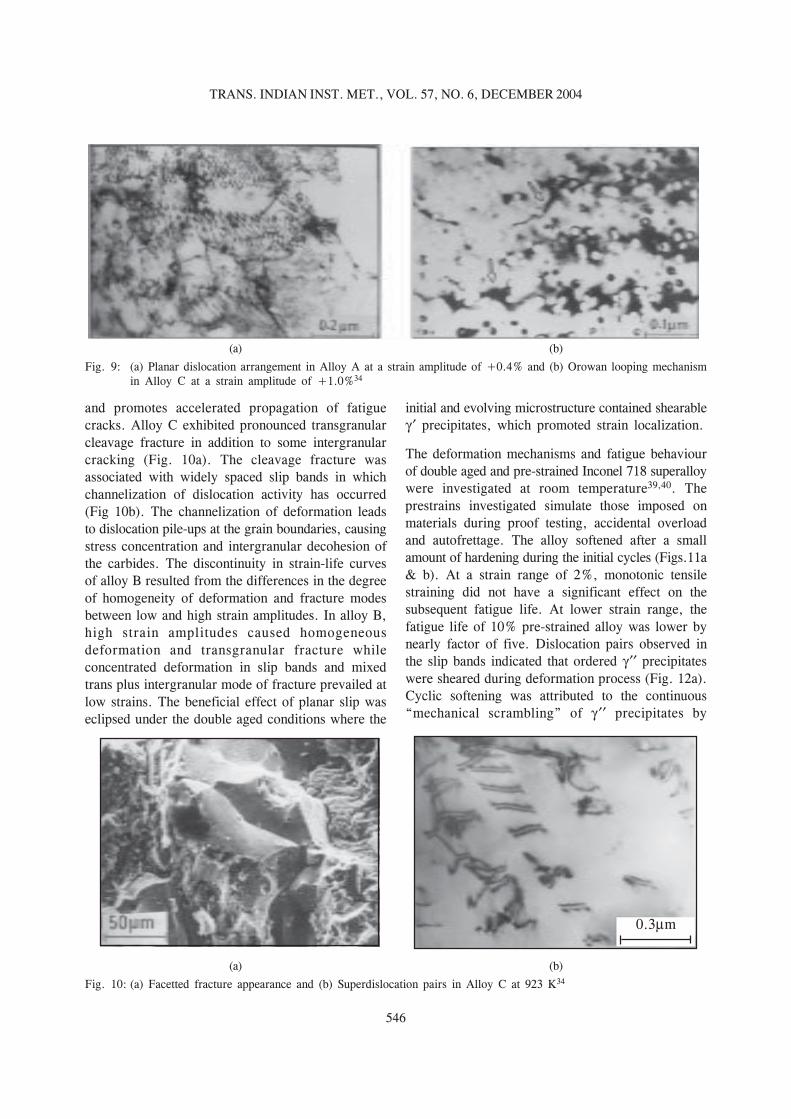
Detailed investigations have been performed tounderstand the TMF behaviour of 316L(N) StainlessSteel used in FBRs. The feasibility of generatingreliable TMF deformation and life data was establishedby conducting several exploratory tests under in-phase(wherein the maximum temperature and peak tensilestrain coincide) and out-of-phase (maximumtemperature and peak compressive strain coincide)testing conditions (Fig. 18). Exploratory tests wereconducted to optimize the sample design,
552
TRANS. INDIAN INST. MET., VOL. 57, NO. 6, DECEMBER 2004
configuration of induction coils and appropriateheating and cooling rates in order to reduce thetemperature gradients in the sample at the strain andtemperature reversals of the TMF cycle. A procedurewas established to ensure proper phasing betweentemperature and mechanical component of the strainby providing thermal strain compensation as afunction of real-time specimen temperature, whichinvolved subtraction of thermal strain from total strainduring TMF test on a real-time basis and establishingthe mechanical strain as the controlling parameter.The studies on austenitic stainless steels revealedthat the mechanical strain rate shall be kept
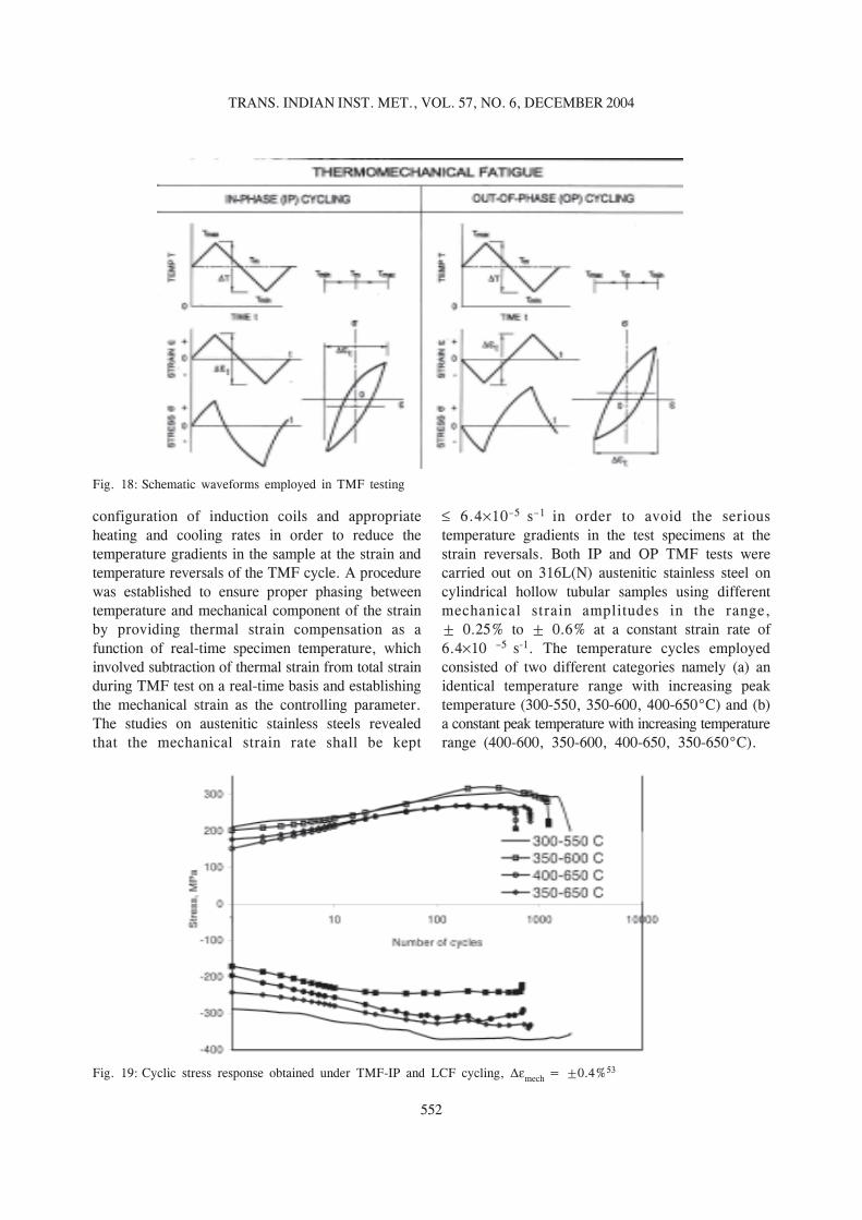
6.4 10–5 s–1 in order to avoid the serioustemperature gradients in the test specimens at thestrain reversals. Both IP and OP TMF tests werecarried out on 316L(N) austenitic stainless steel oncylindrical hollow tubular samples using differentmechanical strain amplitudes in the range,± 0.25% to ± 0.6% at a constant strain rate of6.4 10 –5 s-1. The temperature cycles employedconsisted of two different categories namely (a) anidentical temperature range with increasing peaktemperature (300-550, 350-600, 400-650°C) and (b)a constant peak temperature with increasing temperaturerange (400-600, 350-600, 400-650, 350-650°C).
Fig. 18: Schematic waveforms employed in TMF testing
Fig. 19: Cyclic stress response obtained under TMF-IP and LCF cycling, mech = ±0.4%53

553
BHANU SANKARA RAO : COMPLEXITIES IN FATIGUE OF ENGINEERING MATERIALS AT ELEVATEDTEMPERATURES
In both IP and OP conditions the fatigue lifedecreased with increase in peak temperature of theTMF cycle at constant temperature interval (Fig.19)53. As the peak temperature of TMF cycle wasincreased, the differences in lives of IP and OP testswere narrowed down (Table 2). TMF life in out-of-phase cycling was lower than that in the in-phasetests in the low temperature regimes (Fig. 20), whilein the creep temperature regime, the IP tests yieldedlower lives. With the peak temperature kept constantin the creep range (650oC), and increasing the lowertemperature of TMF interval (350 to 400oC), thefatigue life decreased both in IP and OP conditions(Table 2). The differences in IP and OP tests increasedwith reduction in strain amplitude.
Table 2TMF AND LCF LIFE DATA ON 316L(N) STAINLESS
STEEL AT VARIOUS TEMPERATURES ( MECH = ±0.4%)
Temperature TMF life Isothermalrange, T LCF life
oC at maximumIn-Phase Out-of-Phase temperature
(Tmax)
300-550 2093 1312 693
350-600 1210 1000 835
400-650 585 853 672
400-600 1221 709 835
350-650 811 1256 672
Crack initiation and propagation was transgranular inboth IP and OP conditions when the peak temperatureof TMF cycle was less than 600oC (Fig. 21a). In thetests with the peak temperature at 650oC, OP testsdisplayed transgranular fracture while mixed transplus intergranular mode of fracture occurred in IPtests (Fig. 21b). Influence of creep on the TMFdamage was evident in the form of extensiveintergranular cracking in the 400-650°C IP test. Therelatively higher stress response seen under OP cyclingin the lower temperature regimes shortened the crackinitiation and propagation lives contributing to theoverall reduction in life. At very high temperatures,IP cycling proved to be more deleterious as aconsequence of a creep-dominated intergranularcracking intersperced with oxidation effects. Influenceof oxidation was more prominent in the IP tests asa consequence of the cracks remaining open at thehigh temperature end of the TMF cycle, therebyallowing easy environmental access to the crack tip.The isothermal tests conducted concurrently at thepeak temperatures employed in TMF cycles (550°Cand 600°C) displayed lower lives compared to bothIP and OP tests (Table 2). The IP and OP TMF lives(400-650oC) were lower than isothermal livesobserved at 650oC.
4.2 Dynamic Stain Ageing Effects in TMF ofSuperalloys54-58
The effects of DSA on TMF behaviour have beenexplored by conducting detailed investigations on
Fig. 20: Comparative stress response: IP and OP cycling at, mech = ±0.4%53

554
TRANS. INDIAN INST. MET., VOL. 57, NO. 6, DECEMBER 2004
Fig. 21: (a) Oxidation-assisted mixed mode cracking under 400-650°C IP cycling, (b) SEM fractograph showing creep-dominated IG cracking interspersed with clearly defined striations in 316L(N) stainless steel
tests the maximum and minimum temperatures wereabove and within the DSA range respectively. Thetest with T = 400-6500C is entirely within theDSA range. The evolution of tensile and compressivestresses under IP TMF conditions with varioustemperature intervals are summarized in Fig. 22,tensile stress response curves of selected isothermaltests are also shown to facilitate comparison. It must
Haynes 188 Superalloy in four temperature intervals( T = 350-550, 400-650, 500-750 & 600-8500C).In this alloy DSA was found to occur over a widetemperature range between approximately 400 to700oC5. In the TMF test with T = 350-5500C, themaximum and minimum temperatures were withinand below the DSA range, respectively (for a strainrate of 10-4 s-1), while in the 500-750 and 600-8500C
Fig. 22: Cyclic maximum stress amplitudes of TMF and LCF with m = 0.8% and strain rate = 10-4 s-1
(a) (b)
Haynes 18814101 −−×=ε s&
555
BHANU SANKARA RAO : COMPLEXITIES IN FATIGUE OF ENGINEERING MATERIALS AT ELEVATEDTEMPERATURES
be mentioned that each TMF test is represented bytwo curves, one showing the stress amplitude at themaximum temperature and the other showing the stressamplitude at minimum temperature. Further, forviewing simplicity, all stress amplitudes are shownas being positive (tensile) whereas in IP tests, theminimum temperature amplitude shown correspondsto compressive stress. In the isothermal fatigue tests,tensile and compressive stress amplitudes in any givencycle were essentially equal, whereas in the TMFtests, mean stresses developed as a consequence ofthe dynamic temperature conditions. IP TMF testsdeveloped a compressive mean stress, that is, thecompressive stress amplitudes were higher than thetensile stress amplitudes, whereas OP TMF conditionsled to tensile mean stresses. The mean stress wasmild in the 350-5500C test, however, the other TMFtests experienced significant mean stresses whichgenerally tended to increase with cycling. The meanstresses developed were particularly large when themaximum temperature of the TMF cycle was aboveand the minimum temperature was within the DSArange. This result was due to the fact that DSAenhanced hardening was prevalent at one extreme ofthe cycle and softening due to the thermal recoveryeffects was prevalent at the other extreme.
In all the TMF tests, the maximum stresses achievedjust prior to the onset of failure at the maximumtemperatures of the cycles were almost identical tothose attained in corresponding isothermal tests;however, the number of cycles needed to attain themaximum in each of the TMF tests was less thanthose in the isothermal tests. In contrast, the maximumstresses achieved at the minimum temperatureextremes in the TMF tests were not well representedby the isothermal tests performed at correspondingtemperatures. This may suggest that the TMFmacroscopic behaviour is most influenced by thesubstructural features associated with the peaktemperature.
In general, the lower temperature peak stressesexperienced greater increases in the TMF testsshowing significant deviations from the correspondingisothermal tests. This effect was most pronounced inthe tests conducted with a temperature interval of400-6500C. The maximum hardening rates andmagnitudes experienced by the 4000C TMF peaksfar exceeded those displayed isothermally at 4000C.
This indicates that the TMF stress hardening at 4000Ccould not have been anticipated from the isothermaldata. Further the stress values achieved far exceeded(by 25 to 35%) than those experienced isothermallyat 6500C. This is a significant result considering thatthe 6500C isothermal values represent the maximumfor the entire isothermal data base. This isothermallyunbounded behaviour is clear evidence ofthermomechanical path dependence, as the materialbehaviour observed at 4000C is profoundly influencedby the deformation substructure developed over thefull T. Although the minimum temperature peakstresses in the 500-7500C cycle showed the excessiveincrease due to DSA effects when compared to theisothermal tests at 5000C, the amount of hardeningwas far less than that obtained in the 400-6500CTMF tests, because part of the cycle remained in therange where thermal recovery effects becameoperative. In the TMF tests with T = 600-8500C,where the main fraction of the cycle involves loadingabove the DSA range, it is apparent that the thermalrecovery effects have become substantial, causing thehardening mechanisms associated with DSA to beless effective at the lower temperature extreme of thecycle.
5. DEVELOPMENT OF FATIGUEDESIGN CURVES FOR THICKSECTION FORGINGS OF 9CR-1MOFERRITIC STEEL59-61
Advances in steam cycle conditions of the FBRs towithstand temperatures upto 823 K depend on theability to process and fabricate heavy sectioncomponents from ferritic steels such as 9Cr-1Mo andits derivatives. Steam generators require massive tubeplates to operate continuously at temperatures upto793 K. LCF and creep-fatigue data base for ferriticsteels for sections beyond 32mm is not available andthe guidelines for the fatigue design have not beengiven until recently for thick section ferritic alloys inany of the codes. Investigations were conducted on300 mm thick 9Cr1Mo tube plate to examine whetherthe LCF data available on thin section bar and sheetmaterials could be adequately utilized for the designof thick-section components in the range723-793 K59-61. The alloy in simulated post weld heattreatment condition exhibited predominantly cyclicsoftening (Fig. 23a). Total strain LCF resistance of

556
TRANS. INDIAN INST. MET., VOL. 57, NO. 6, DECEMBER 2004
thick section tube plates of 9Cr-1Mo was inferior tothat of hot rolled thin sections tested in eithernormalized plus tempered or in simulated thick-sectionheat treatment conditions (Fig. 23b) owing to itscoarse grain size. Within the range of strain amplitudesexamined, the experimental data on fatigue life atelevated temperatures were found to match well withthe LCF lives predicted by the Tomkins crack growthmodel. All the important parameters required for lifeprediction using Tomkins crack growth equation werededuced from the deformation and fracturecharacteristics obtained on the alloy during tensionand LCF tests at various temperatures on thick sectionmaterial. The total strain-life relationship comprising
of Basquin and Coffin-Manson equations wasemployed to extrapolate the experimental fatiguecurves upto 2 10 6 reversals. Using the fatigue datagenerated on small specimens and employing thephilosophy embodied in the ASME code case N-47,fatigue design curves have been developed for thicksection 9Cr-1Mo steel. The extrapolated fatiguecurves were used to construct tentative fatigue designcurves by applying a reduction factor of 20 on thenumber of reversals or a factor of two on the strainamplitude (Fig. 23c). These factors cover effects suchas environment, size, surface finish and scatter of thedata. It was generally observed that at low strainamplitudes division of the strain amplitude by a factor
Fig. 23: a) Cyclic stress response curves at 793 K, b) Fatigue endurance data of 9Cr-1Mo steel on thick section forged tubeplates and thin section hot rolled bars for different heat treatment conditions, c) Experimental and predicted curvesof total strain amplitude against number of reversals and the fatigue design curve at 793 K and d)Fatigue design curvesat different temperatures60

557
BHANU SANKARA RAO : COMPLEXITIES IN FATIGUE OF ENGINEERING MATERIALS AT ELEVATEDTEMPERATURES
of two gave the lowest curve, while at high strainamplitudes a reduction of factor of 20 on the numberof reversals yielded the lowest curve. The moreconservative of the two estimates in the differentsegments were joined together to obtain the fatiguedesign curves for continuous cycling for thetemperature range 723-793 K (Fig. 23d). In order toobtain the design curves beyond 2 106 reversals, anextrapolation technique following the French designcode RCC-MR was adopted. A fatigue design curveapplicable for the temperature range 300-644 K wascomputed based on room temperature tensileproperties, incorporating the concept of fatigue limitand mean stress.
6. FATIGUE BEHAVIOUR OF STAINLESSSTEEL WELDMENTS
Often, fracture in fabricated engineering structuresinitiates at welded joints. The welding processproduces local microstructural changes that are seldomconsidered in the operation design analysis. Themetallurgical condition of the material is changed;local residual stresses of magnitude well beyond thecomponent design stress may be introduced andfrequently defects are produced during the weldingprocess which sometimes go undetected. These defectstogether with unfavourable design geometries providefurther stress concentrations, The combined effectsof these on LCF behaviour are often overlooked bythe designer, fabricator and user of the components.Failures in the welded joints are prevented throughthe use of safety factors on stresses and strains andby requiring the welds to be located in the regions ofrelatively low stresses. In the absence of substantialinformation on welds, ASME boiler Vessel code CaseN-47 imposes a limit on the design strains in theweld regions at one-half of the value permitted in thebase metal for applications at elevated temperatureswhere creep effects are significant. The allowablenumber of fatigue cycles is also one-half of the valuepermitted for the parent metal. There is a seriousconcern about the conservatism introduced in thedesign rules. In austenitic stainless steels the -ferriteintroduced to reduce their tendency to hot crackinggets transformed to brittle -phase when thesematerials are exposed to elevated temperatures forextended periods of time. The transformationbehaviour of the -ferrite and its effects on LCF
behaviour of SS welds and weldments are requiredbefore the variation in properties between the weldmetal and base metal are treated explicitly andquantitatively. In view of this, a comparativeevaluation of LCF lives and cyclic stress-strainproperties, deformation and fracture behaviour hasbeen conducted on type 304 SS base, 308SS weldsand 304/308 SS weldments62 as well as 316L(N)base, 316 welds and 316L(N)/316 SS weldments63,64.Creep-fatigue interaction of 308, 316(N) and 316 SSwelds has been explored65-67. Assessment of the effectof weld imperfections on LCF properties of 308 SSwelds has also been made68.
A brief discussion of the results obtained on the LCFbehaviour of 304 base, 308 SS weld and 304/308 SSweld joints at 823 and 923 K and the effect ofdiscontinuities on LCF behaviour at 823 K is includedin this section. Microstructure of base metal consistedof equiaxed grains of 75 m while weld metal wascomposed of long columnar grains and vermicular d-ferrite (9 ferrite number) distributed in austenitematrix. The weldments displayed coarse grainedregion in heat affected zone and few deformationbands giving indication of the presence of residualstresses. The cyclic stress response behaviour of thebase metal, weld metal and the weld joint differedconsiderably (Fig. 24). Base metal showed rapid initialhardening followed by well-defined saturation stressstage. Type 308 SS weld metal exhibited continuouscyclic softening. Weldments initially hardened andthen softened gradually prior to the rapid stressdecrease. Weldments subjected to a stress relievingheat treatment displayed lower response stressescompared to the untreated weldments. The initialhardening observed in base metal has been attributedto the combined effects of dislocation-solute atomand dislocation-dislocation interactions, while thestress saturation has been found to have correlationwith the development of well defined cell structure.The TEM studies on 316 SS weld metal provided theinformation on the origins of cyclic softening inaustenitic weld metals64. The untested weld metalrevealed very high density of dislocations anddislocation tangles in austenite matrix withcomparatively lower density of dislocations in-ferrite. After LCF testing, the dislocation density
in austenite was considerably reduced while -ferritewas free from dislocations. It was inferred that during

558
TRANS. INDIAN INST. MET., VOL. 57, NO. 6, DECEMBER 2004
Fig. 24: Cyclic stress response curves for (a) base, (b) all weld and (c) weldments specimens at 823 K62
LCF resistance while 304/308 SS weld joints showedthe least at 823 K and 923 K (Fig. 25). Weld metalpossessed lower life than base metal at 823 K anddisplayed slightly better life at 923 K at lower strain
LCF, dislocation tangles break down, and subsequentannihilation of dislocations of opposite sign occursduring their to and fro motion, promoting cyclicsoftening. Type 304 SS base metal exhibited better
Fig. 25: Strain-life plots for base, all-weld and weldments at a) 823 K and b) 923 K62

559
BHANU SANKARA RAO : COMPLEXITIES IN FATIGUE OF ENGINEERING MATERIALS AT ELEVATEDTEMPERATURES
Fig. 26: (a) Influence of testing variables on the fraction of delta ferrite transformed during fatigue deformation and (b) Crackpath diversion along the transformed delta ferrite regions of all-weld material at 923 K62
amplitudes. The reduction in life was noticed for allthe conditions when the temperature was raised from823 to 923 K. The poor fatigue resistance ofweldments has been ascribed to the shortening ofcrack initiation phase and to poor crack propagationresistance of the coarse grained region of the heataffected zone. Solution annealing (at 1173 K for 3h)the weldments prior to LCF testing caused inimprovement in fatigue life probably due to theelimination of residual stresses from the weld joint.The reduction in life with increasing temperatureresulted from the combined effects of an increaseinelastic strain generated in a cycle and from theeffects of oxidation-assisted crack initiation andpropagation in all the three material conditions.Vermicular -ferrite in welds and weldmentstransformed to M 23 C6 and -phase during LCFtesting. The transformed portion of -ferrite increasedwith increasing number of cycles to failure andincreasing temperature (Fig. 26a). The transformationof -ferrite was more rapid in weldments than in all-weld metal. The fine duplex austenite-ferritemicrostructure in the weld metal, with its transformed
phase boundaries, offered greater resistance tothe extension of fatigue cracks by causing thedeflection of crack path (Fig. 26b). Crack deflectioncould cause reduced stress intensity at the crack tipwith an associated reduction in the crack propagationrate. However, at 823K, the transformation of the -ferrite to was less and the beneficial effects ofcrack deflection could not be seen, as a result theweld metal exhibited lower life than base metal.
Detailed investigations have been performed forassessing the significance of weld discontinuities onLCF behaviour of 308 SS welds. Weld pads wereprepared by shielded metal arc welding process.Porosity and slag inclusions were introduceddeliberately into the weld metal by grosslyexaggerating the conditions normally causing suchdefects (Fig. 27a). Base metal showed higher fatiguelife than sound weld metal at all strain amplitudes(Fig. 27b). The presence of porosity and slaginclusions in the weld metal led to significantreduction in life (Fig.27b). Porosity on the specimensurface has been found particularly harmful andcaused a reduction in life by a factor of seven relativeto sound weld metal. Defect combination of porosityand slag inclusions was found more deleterious thanthe case when either the slag inclusions or porositywas present alone. Discontinuities acted as crackinitiation sites and also enhanced crack propagation.
7. CREEP-FATIGUE-ENVIRONMENTINTERACTIONS
7.1 Hold Time Tests on Alloy 617 at 1223 K
The effects of hold-time and strain rate on creep-fatigue-environment interactions are explained belowwith the aid of the tests performed on Alloy 617 at1223 K in simulated helium gas environment of hightemperature gas cooled reactor69-71. The helium gaswas composed of 500, 20, 1.5, 15, 1 and 5 barof H2, CH4, H2O, CO, CO2 and N2 respectively.

560
TRANS. INDIAN INST. MET., VOL. 57, NO. 6, DECEMBER 2004
Fig. 27: a) Description and location of defects in LCF specimen of weld metal and b) Strain-life plots of 304 SS base and308 SS sound weld and defective weld metal. Numbers at data points refer to the samples68
during slow tensile stress relaxation period of thetensile holds. Figure 29 clearly illustrates thedevelopment of intergranular cavities (R type)associated with grain boundary precipitates. Inaddition to the bulk cavity damage, a large numberof grain boundary wedge cracks were observed in thenear-surface regions in the areas that were free fromM23C6 particles particularly when the tension holdtimes were more than 10 min. (Fig.30a). The damagedue to grain boundary oxidation was found to beconsiderable at longer tensile holds (Fig. 30b). Sincemost of the oxides are intrinsically brittle, the fatiguecracks in tests with longer hold periods initiated inoxides which are formed preferentially at surface-connected grain boundaries. The oxidation-inducedsurface intergranular cracks penetrated deeply intothe interior and merged with independently formedintergranular wedge cracks in the near-surface regionsand R-type cavities in the bulk.
Compression hold tests did not exhibit creep cavitiesin the specimen interior. In addition, none of thesefeatures such as a thick surface oxide layer, carbidefree zones, and wedge cracking in the near-surface
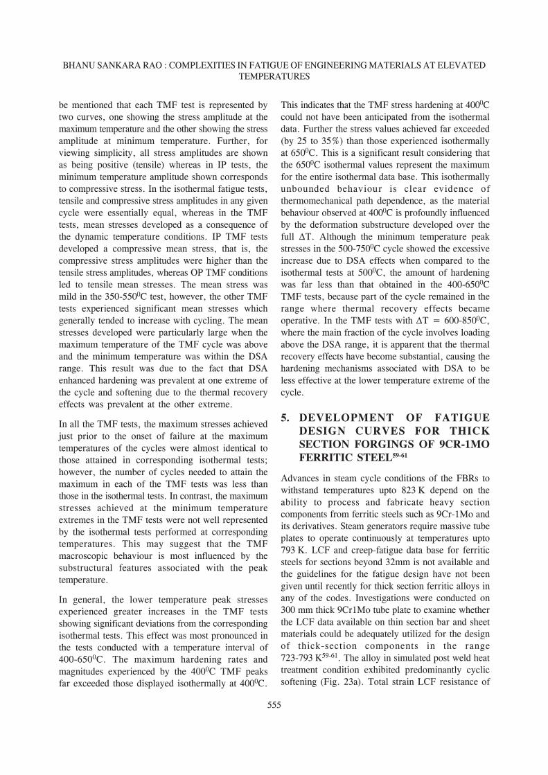
The fatigue life reduction factor (R) is defined as theratio of life recorded for a given strain rate or holdtime to the reference life value for continuous cyclingat a strain rate of 4 x 10⁻³ s-1. The reduction in thestrain rate caused only a small reduction in fatiguelife in the continuously cycled tests (Fig. 28).Irrespective of the position of hold at peak strain ina cycle, tension hold time always reduced fatigue lifein comparison with continuously cycled tests of equalcycle duration; these reductions were only slightlyhigher than those observed for compression only holdtests and very much larger than those involvingsymmetrical hold periods in tension and compression.Tension plus compression holds exhibited only a smallreduction in life with those compared to continuouslycycled tests. In the continuously cycled tests failurewas always transgranular with no indication of creepor oxidation damage observed.
The reductions in fatigue life which occurred whentensile hold periods were applied were principallydue to the interaction between surface initiated fatiguecrack and interior creep cavitation associated withgrain boundary carbides. These cavities were formed
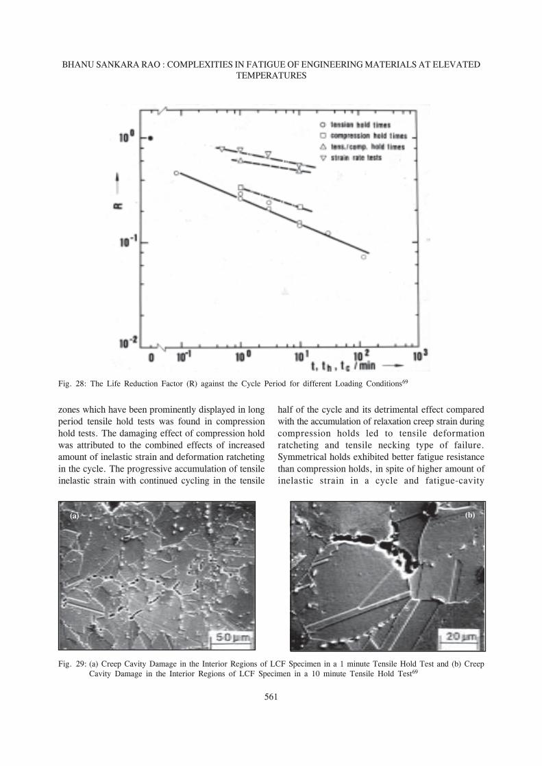
561
BHANU SANKARA RAO : COMPLEXITIES IN FATIGUE OF ENGINEERING MATERIALS AT ELEVATEDTEMPERATURES
zones which have been prominently displayed in longperiod tensile hold tests was found in compressionhold tests. The damaging effect of compression holdwas attributed to the combined effects of increasedamount of inelastic strain and deformation ratchetingin the cycle. The progressive accumulation of tensileinelastic strain with continued cycling in the tensile
half of the cycle and its detrimental effect comparedwith the accumulation of relaxation creep strain duringcompression holds led to tensile deformationratcheting and tensile necking type of failure.Symmetrical holds exhibited better fatigue resistancethan compression holds, in spite of higher amount ofinelastic strain in a cycle and fatigue-cavity
Fig. 28: The Life Reduction Factor (R) against the Cycle Period for different Loading Conditions69
Fig. 29: (a) Creep Cavity Damage in the Interior Regions of LCF Specimen in a 1 minute Tensile Hold Test and (b) CreepCavity Damage in the Interior Regions of LCF Specimen in a 10 minute Tensile Hold Test69
(a) (b)

562
TRANS. INDIAN INST. MET., VOL. 57, NO. 6, DECEMBER 2004
interactions in the vicinity of fracture zone, probablybecause of the non-existence of deformation ratchetingin the cycle. The cavities in the fracture zone insymmetrical holds resulted from irreversible sheardeformation.
7.2 Micromechanisms Governing HighTemperature Fatigue During Unequal RampRate Tests in Alloy 800H
The damage mechanisms influencing the LCFbehaviour of Alloy 800H at 1123 K have beenevaluated under conditions of equal tension/compression ramp rates (fast-fast, slow-slow) andasymmetrical ramp rates (slow-fast, fast-slow) in
tension and compression 71-73. The effects of waveformon fatigue life of Alloy 800H is shown in Table 3.
The fatigue lives displayed by different loadingconditions were in the order: F-F>S-S>F-S>S-F.The cyclic stress response was strongly dependent onwaveform. The cyclic stress response was symmetricalF-F and S-S tests (Fig. 31). Asymmetrical testsdisplayed unequal stress amplitudes in tension andcompression. The half-life hysteresis loops of F-Sand S-F tests revealed large amounts of tensile andcompressive mean stresses, respectively. The fracturemodes depended on the tension going deformationrate. The fast deformation rate during tension goingled to transgranular crack initiation and propagation
Table 3INFLUENCE OF UNEQUAL RAMP RATES ON ENDURANCE OF ALLOY 800H AT 1123 K
Fig. 30: a) Wedge Cracking in Carbide Depleted Regions in a 10 minutes tensile hold test and (b) Oxidation in 120 min.Tensile Hold Test69
(a) (b)
. .
. .

563
BHANU SANKARA RAO : COMPLEXITIES IN FATIGUE OF ENGINEERING MATERIALS AT ELEVATEDTEMPERATURES
(Fig.32a), while slow ramping caused intergranularcrack initiation and propagation. Ramping at differentrates in tension and compression created deformationratcheting in F-S and S-F tests and influenced thefailure modes to a greater extent. Since deformationrates in the tension going direction are different fromthose in the compression going direction in F-S andS-F tests, plastic deformation in tension and creep incompression were accumulated, respectively, underF-S cycling, whereas under S-F loading creep intension and plastic deformation in compression wereaccumulated, respectively. The deformation ratchetingof both plasticity in one direction and creep in anotherconstitutes a serious damage mode in the assymetricaltests. For F-S conditions the fracture occurred bytensile necking instability (Fig. 32b). Theaccumulation of microscopic inelastic tensile strain,which is not recovered during the compressive portionof the cycle, would contribute to this phenomenon.The strains can become concentrated in the regions
of initial plasticity, and this detrimental effect isadditional to other time dependent effects. In S-Fconditions, the inclusion of slow tensile strain rateinto the fatigue cycle enabled creep cavitation damageto accumulate at grain boundary particles in the bulk(Fig.33a). In addition to intergranular creep damagea large number of surface intergranular cracks hadinitiated and grown to depths of about 1 mm (Fig.33b). Near the surface, the environmental damageeffects were severe and the diffusion of environmentalspecies down the grain boundary can cause a reductionin the boundary cohesive strength. This effect mayenhance sliding in the contaminated grain boundaryand hence promote subsequent cracking. Oxidationhas been found to affect primarily the initiation andnear threshold crack growth stages in S-F tests. Cycliclife was influenced by synergestic interactions betweena number of time-dependent mechanisms. The damagemodes governing the fatigue life of Alloy 800H as afunction of waveform are summarized in Table 4.
Fig. 31: Effect of Wave Shape on the Cyclic Stress Response
Fig. 32: a)Transgranular cracking during a fast-fast test, and b) Transgranular fracture at 1123 K in a fast-slow test
Table 4SUMMARY OF WAVEFORM EFFECTS
8. ACHIEVEMENT OF HIGH FATIGUERESISTANCE IN INTERMETALLICS
There would be considerable benefit in developingnew structural materials where high use temperaturesand strength coupled with low density are minimumcapabilities. Nickel aluminides exhibit considerable
(a) (b)

564
TRANS. INDIAN INST. MET., VOL. 57, NO. 6, DECEMBER 2004
potential for near-term application in various branchesof modern industry due to number of propertyadvantages including low density, high meltingtemperature, high thermal conductivity, and excellentenvironmental resistance, and the amenability forsignificantly improving creep and fatigue resistancethrough alloying. However, the B2 nickel aluminidesare challenged by lack of ambient temperature ductilityand toughness. These deficiencies severely imposelimits on the fabrication and forming of thesematerials. Furthermore, binary NiAl suffers from lackof strength and poor creep resistance at and above1000 K. Poor creep resistance in turn affects LCFlives at low strain ranges due to interaction of creepdamage. Attempts have been made to improve thefatigue resistance of the NiAl by understanding theeffects of manufacturing process and micro alloying.
8.1 Effects of manufacturing processes on straincontrolled low cycle fatigue behaviour ofpolycrystalline NiAl
The NiAl samples were produced by three differentprocessing routes: hot isostatic pressing (HP) of prealloyed powders, extrusion of pre-alloyed powders(PE), and extrusion of vacuum induction meltedingots (CE)74. The HP alloy had larger grains andlarger variation in grain size compared to the fullyrecrystallized extruded materials, CE and PE. TheHP material contained prior particle boundaries thatwere composed of narrow stringers of fine Al2O3particles. The CE material consisted of internal voids,which were aligned parallel to the extrusion axis.Despite the 12:1 reduction ratio during extrusion,
the CE alloy possessed residual porosity, owing tothe presence of entrapped gas. The PE alloy wasfully consolidated with fewer defects than the CE orHP material.
CE and PE alloys exhibited similar lives underidentical strain ranges (Fig. 34a). The HP alloydisplayed shorter lives than the extruded materials,with an increasing difference in life at low strainranges. Typically, the alloy in all processingconditions exhibited relatively little cyclic hardeningor softening at 1000K. However, the HP alloydisplayed a higher cyclic stress response over theentire life range compared to the extruded alloys(Fig. 34b). All the three alloys exhibited intergranularcrack initiation and propagation prior to the onset oftransgranular cleavage overload failure (Fig. 35). TheHP alloy had much smaller zone of slow and stableintergranular crack growth compared to the extrudedalloys; higher response stresses would act to reducethe critical crack size for final fracture reducing thenumber of cycles to failure. The relatively fast andunstable transgranular cleavage has set in much earlierin the HP alloy. In the case of HP alloy, the samplescycled at low strain ranges exhibited much shorterlives than would be expected by extrapolation fromhigh strain range regime of the strain-life plot. Thediscontinuity in the strain-life curve in the HP alloyhas occurred as a consequence of the operation ofdifferent damage mechanisms in the high and lowlife regimes. Failure of HP alloy at low strain rangeswas attributed to an environmentally assisted fatiguedamage mechanism that was aggravated by extensivevoid formation on grain boundaries owing to creep.
Fig. 33: a) Intergranular cavitation at 1123 K and b) Intergranular crack initiation in the surface oxide scales in a slow-fasttest.
.
(a) (b)

565
BHANU SANKARA RAO : COMPLEXITIES IN FATIGUE OF ENGINEERING MATERIALS AT ELEVATEDTEMPERATURES
Fig. 34: a) Fatigue life curves on a total strain range basis ; b) Effect of processing on stress response of binary NiAl at1000 K
Fig. 35: Fracture surface of HP sample test at 1000 K. Arrows indicate extent of slow crack growth.

566
TRANS. INDIAN INST. MET., VOL. 57, NO. 6, DECEMBER 2004
At high strain ranges, life was predominantly dictatedby fatigue crack initiation and growth. The aluminaparticles on the grain boundaries acted as preferentialsites for nucleation of creep cavities in the HPcondition. These results indicate that the oxide particlesin the HP samples are a major source of concern.These have significantly contributed to the largeamount of scatter observed in life at low strain ranges.It has been suggested that strict control over the
powder cleanliness needs to be exercised in order toimprove the fatigue life in the alloys processed byHP route.
The comparative evaluation of fatigue life of NiAland lives of various turbine disk and blade alloys attemperatures of approximately 1000 K are made inFigs. 36a and b. Binary NiAl exhibited superior fatiguelife when compared to most superalloys on a plasticstrain basis, but inferior to most superalloys on stress
Fig. 36: (a) Fatigue life of NiAl compared to Ni base superalloys on plastic strain range basis at 1000 K.(b) Fatigue lifeof NiAl compared to Ni base superalloys on stress range basis at 1000 K.
Plat
ic s
trai
n ra
nge,
per
cent
Str
ess
rang
e, M
Pa
Fatigue life, Nf, cycles
Fatigue life, Nf, cycles

567
BHANU SANKARA RAO : COMPLEXITIES IN FATIGUE OF ENGINEERING MATERIALS AT ELEVATEDTEMPERATURES
Fig. 37: Effect of processing route on strain controlled LCF behaviour of binary NiAl
Fig. 38: Stress response curves for NiAl alloys at a) high and b) low strain ranges.

568
TRANS. INDIAN INST. MET., VOL. 57, NO. 6, DECEMBER 2004
basis. The poor performance of binary NiAl on astress range basis is due to its low yield strengthcompared to the superalloys. In view of this attemptshave been made to improve the strength of the alloyby alloying with nitrogen as well as zirconium.
8.2 Microalloying effects on the high temperaturefatigue behaviour of NiAl
The total strain fatigue resistance of NiAl (N) washigher than binary NiAl in the range of strainamplitudes examined (Fig. 37)75-78. Zirconiumadditions were even more beneficial for fatigue lifeat total strain ranges below 0.38%. However, onincreasing the strain from 0.38% to 0.40%, the Zr-doped alloy showed a drastic reduction in life due torapid exhaustion of its already limited ductility. Thereare clear differences in the stress response behavioursof binary, nitrogen-doped and Zr-doped alloys(Fig. 38). Zirconium-doped alloy displayed muchhigher response stresses than the other two alloys.NiAl (Zr) exhibited a short period of cyclic hardeningand attained a maximum stress in the very early stagesof cyclic life. Conversely, NiAl and NiAl (N)experienced cyclic softening initially followed by aperiod of stable stress response. Zirconium dopingsignificantly improved cyclic strength and led to highcyclic strain hardening exponent, while the effect ofnitrogen was only marginal on these properties.
The LCF behaviour of these alloys were significantlyinfluenced by the relation between the test temperatureand their respective Brittle to Ductile TransitionTemperature (BDTT). Since the BDTT of NiAl (Zr)(1100 K) was higher than test temperature,substructural recovery was not significant and thisled to more homogenous distribution of dislocationswithin the grains (Fig. 39). Additionally, Zr atomsare very effective in pinning dislocations below theBDTT and increasing the viscous drag force ondislocations at higher temperatures. Consequently,the mutual interactions between dislocations and solidsolution hardening due to Zr atoms resulted in highercyclic stress response. BDTT of the binary andN-doped alloys (~630 K) was much lower than thetest temperature, significant recovery was able tooccur during testing resulting in lower responsestresses. The marginal improvement in cyclic stressresponse of the N-doped alloy over the binary NiAlhas been associated with dislocation pinning by thefinely dispersed AlN particles in the former alloy.
The two stages in the strain-life plot of NiAl (Zr)occurred as a consequence of the change in fracturebehaviour from slow and stable intergranular crackgrowth at strain ranges 0.38% to brittle cleavage-dominated overload fracture at high strain ranges(Fig. 40). At strain ranges above 0.38%, the peaktensile stress reached the monotonic cleavage fracture
Fig. 39: Deformation substructures in Cyclically deformed NiAl Alloys at a total strain range of 0.3% (a) NiAl, (b) NiAl(N) and (c) NiAl(Zr)
(a) (c)(b)

569
BHANU SANKARA RAO : COMPLEXITIES IN FATIGUE OF ENGINEERING MATERIALS AT ELEVATEDTEMPERATURES
stress of the Zr-doped alloy in less than 100 cycles,enabling fast crack growth by transgranular cleavage.At strain ranges less than 0.38%, the peak tensilestresses remained at much lower level than thecleavage fracture stress. In general, fatigue lives aregoverned by the ductility of the material at highstrains and by its strength at low strains. The longerlives of NiAl (Zr) at low strain ranges result from itsbasic capacity to resist the applied strains on the basisof high strength. Both NiAl and NiAl (N) haveshorter lives at low strain ranges due to the synergisticinteraction between fatigue and creep. A higher slopeof the strain range-life plot of NiAl (N) reflects thisinteraction. In order to improve the fatigue resistanceof the N-doped alloy, the grain boundaries have tobe strengthened to reduce grain boundary sliding andthe associated intergranular wedge cracking that wasobserved in these two alloys. Since Zr segregates tothe grain boundaries in NiAl and apparently strengthensthe boundary regions preventing grain boundary
sliding, NiAl (Zr) does not suffer from this problem.It has been found that even the extremely small Zraddition (approximately 0.1 at%) significantlyimproves the fatigue life on a stress range basis;approaching that of superalloys (Fig.41).
Fig. 40: Fatigue damage in NiAl(Zr) (a) Mixed mode fracture with significant cleavage at a strain range of 0.40% and (b)Completely intergranular fracture at a strain range of 0.30%
Fig. 41: Life comparison of NiAl alloys with superalloys onstress range basis at 1000 K.
(a) (b)
Life, Nf
Stre
ss r
ange
, (
MPa
)
(ksi)

570
TRANS. INDIAN INST. MET., VOL. 57, NO. 6, DECEMBER 2004
9. CHALLENGES IN THECHARACTERIZATION OFMICROSTRUCTURE AND STRAINCONTROLLLED FATIGUEBEHAVIOUR OF A CONTINUOUSFIBER REINFORCED MMC
The development of fiber-reinforced metal matrixcomposites (MMC) for structural applications inairframe and aeroengine components necessitates acomprehensive understanding of strain controlledfatigue properties under fully reversed conditions.Although the thicker composites could be fabricatedsuccessfully, the characterization of strain controlledLCF behaviour remains as a challenging task sincethere are no guidelines whatsoever on the specimengeometry, surface finish, the method of attaching thethermocouples to the gauge section and the type ofextensometry that has to be adopted. All theseproblems have been overcome and the suitablespecimen configuration for conducting straincontrolled fatigue tests has been evolved. Appropriatetechniques for characterization of microstructure offiber and composite have been developed.Comprehensive characterization led to theunderstanding of the starting microstructure of thecomposite, fatigue life of the composite in relationto the base material, cycle dependent changes in stressresponse and modulus of the base material and thecomposite, in-situ cyclic deformation of the matrixin the composite, deformation induced precipitationin the in-situ matrix and progression in thedevelopment of fatigue damage behaviour of thecomposite. The MMC chosen for the investigationswas composed of Ti-15V-3Cr-3Al-3Sn (in wt%)matrix reinforced by continuous, unidirectionalSiC(SCS-6) fibers. The 7.7 mm thick compositesconsisted of 32 plies of SCS-6 fibers and had a fibervolume fraction of 35%. All the fatigue specimenswere heat treated prior to fatigue testing in highvacuum (10-6 Torr) at 973 K for 24 hours. Thesalient features of the starting microstructure include(i) uniform distribution of lath shaped particles inthe matrix of b.c.c . -phase, (ii) the occurrence ofTiC on some of the grain boundaries, (iii) preferentialprecipitation of on some of the grain boundariesand (iv) the occurrence of precipitation lean zonesnext to the grain boundaries and surrounding thefibers. The microstructural features of the fiber
consisted of the carbon core, the pyrolytic coating(inner), small grained SiC, large grained SiC, thecarbon rich coating on the fiber outer surface, thefiber-matrix reaction zone and the matrix80,81. In theprecipitate lean zone surrounding the fibers, matrixwas deformed very heavily, and the microstructurewas characterized by a very high density of planarslip bands on multiple systems (Fig. 42). The densityof slip bands between the fiber rows was graduallydeclined as the distance from the fiber increased Theeffect of strain range on the evolution of cyclic tensilestress response for the unreinforced matrix andcomposite at 700 K (427 0C) are shown in Fig. 43.At all strain amplitudes, the composite exhibited moreor less a stable cyclic stress response from thebeginning82,83. The unreinforced Ti-15-3 alloyexhibited a stable stress response period in the initialstages followed by cyclic hardening at strain rangesbelow 1.5%. Cyclic stress response of the compositewas higher than the matrix material at equal strainamplitudes. Fully reversed strain controlled fatigueresistance of composite is only marginally lower thanthat of base material (Fig. 44). Composite resistedthe imposed strain elastically. Though the stress-strainhysteresis loops of the composite revealed a verylimited amount of plasticity, the TEM examinationof the composite foils illustrated that the in-situ matrixhas accumulated substantial amount of plasticdeformation during cyclic loading.
In-situ matrix deformation and precipitation behaviourwas heterogeneous and varied in a complex manner.TEM microstructure of the composite in the vicinityof fiber after fatigue deformation revealed rows ofsecondary laths in the -grain (Fig. 45). It appearedthat these plates were nucleated along the slip bandsthat were present in the aged microstructure prior tofatigue testing. In contrast to the plates noticed atthe fibers in between the rows, the secondary atother locations has been found to appear in the formof needles and as well as fine aggregates. Uniformlydistributed fine needle-like precipitated morepredominantly in between the plies and particularlyin the central locations of the matrix that was boundedby the four fibers (picture marked Q in Fig. 45b).In general, the aggregates have occurred verypredominantly in the areas close to the lean zonesfound in the starting microstructure. The strain rangeemployed in fatigue testing played a significant role

571
BHANU SANKARA RAO : COMPLEXITIES IN FATIGUE OF ENGINEERING MATERIALS AT ELEVATEDTEMPERATURES
Fig. 42: Deformation substructure in the aged composite at various locations
Fig. 43: Cyclic stress response curves for (a) aged Ti-15-3 matrix and (b) Composite

572
TRANS. INDIAN INST. MET., VOL. 57, NO. 6, DECEMBER 2004
Fig. 44: Strain-Life plots for the Ti-15-3 matrix and Ti-15-3/SCS-6 composite
Fig. 45: (a) Precipitation of secondary in the in-situ matrix of the composite at various locations during fatigue testing( – 0.61%). All the particles in P are s. Large particles in Q and R are p.

573
BHANU SANKARA RAO : COMPLEXITIES IN FATIGUE OF ENGINEERING MATERIALS AT ELEVATEDTEMPERATURES
Fig. 45: (b) Microstructure of the in-situ matrix of the composite at various locations after fatigue testing ( – 0.61%)
fracture. Occasionally, fiber cracking and a fewsecondary cracks were observed in the matrix-fiberinterfacial regions. The TEM investigations suggestedthat the fiber cracking could get initiated at thetransition zone between the coarse grained SiC andouter carbon layer (Fig. 46), and interface betweenpyrolytic coating covering the carbon core andradially grown SiC layer.
in the precipitation behaviour. At low strain ranges,the secondary precipitation was noticed to besignificant and the size of precipitates wascomparatively large.
Polished metallographic sections of the selectedspecimens revealed the dominance of matrix crackingat all the strain ranges; the fibers remained unbrokenand bridged the cracked matrix. This observationsuggests that the matrix cracked before the fiber
Fig. 46: Microstructure of the composite showing the coarse grained SiC, outer carbon (inner) layer and a transition zonebetween them (prior to fatigue testing). Fatigue cracks were noticed in this transition region of the composite( = 1.31%).

574
TRANS. INDIAN INST. MET., VOL. 57, NO. 6, DECEMBER 2004
10. CONCLUDING REMARKS
The basic understanding of high temperature fatiguein engineering materials has vastly improved overthe years. There exists a number of alternative timeand temperature dependent damage processes (Inelasticdeformation, dynamic strain ageing, creep damage,oxidation damage, deformation ratcheting, massiveprecipitation, uniform matrix cavitation etc.) by whicha material’s life in high temperature LCF may becontrolled. Each process occupies a characteristic rangeof temperatures, strain amplitudes, strain rates andhold times and are strongly influenced by type ofmaterial and its initial and evolving microstructure inservice. The limits of their regime of dominancemay be shifted and the cyclic life of the materialwithin a particular regime of dominance may be alteredby varying the cycle type, by changing theenvironment and as a result the occurrence ofmicrostructural instabilities. In high temperature LCFempirical lifetime prediction methods are premisedon the interaction of the fatigue deformation processwith one or more of the alternative time dependentdamage processes presented in this paper. Theapplication of any lifetime prediction method is limitedto the regime of dominance of the particular timedependent process. The identification of theseprocesses and their synergistic interactions and thefixation of their limits of operation will be ofassistance in materials development, selection ofengineering materials for a particular application,development and selection of the most appropriatelife time prediction method and with the definitionof its limits of extrapolation. Because of the largenumber of variables in LCF, Creep-fatigue and TMFtesting and the inherent problem of not being able totest for all possible combinations of variables, it isnecessary to develop a mechanistic understanding ofsynergistic interactions in high temperature fatigue.
ACKNOWLEDGEMENTS
I have a great pleasure in placing on record mygratitude to Dr. Placid Rodriguez for introducing meto research work in mechanical metallurgy, meticuloussupervision of my research work, motivating andcarefully nurturing my career and providing invaluableguidance throughout his stay at Kalpakkam. I amthankful Dr. Baldev Raj, Director, IGCAR,Kalpakkam for his keen interest on my work, constant
support, advice and encouragement without whichthis endeavour would not have been possible. He hasalso motivated me for conducting high qualityresearch work with devotion and commitment toexcellence. It is a pleasure to acknowledge the benefitsof many illuminating discussion I had with him overthe years. In my long and very fulfilling professionalcareer, I have been fortunate to receive tremendoussupport, co-operation and valuable guidance fromDr. S.L. Mannan, Director, Metallurgy and MaterialsGroup, IGCAR, Kalpakkam. The golden period ofour combined research work will forever be gratefullyremembered.
I am indebted to my colleagues Dr. M. Valsan andDr. R. Sandhya for their enthusiastic participation,involvement and active co-operation in the early stagesof our research work on high temperature fatigue.We have shared many of our ideas and excitementswith useful discussion. The present and past membersof Mechanical Metallurgy Division at Kalpakkam whohave been mainly responsible for the large numberof its achievements are Dr. M.D. Mathew, Dr. M.Valsan, Dr. K.G. Samuel, Dr. C. Phaniraj, Dr. G.Sasikala, Dr. B.K. Choudhary, Dr. K. Laha, Dr. R.Sandhya, Dr. V.S. Srinivasan, Mr. A. Nagesha, Mr.R. Kannan, Mrs. S. Latha, Mrs. Vani Shankar, Mrs.K.S. Chandravathi, Dr. E.Isaac Samuel, Mr. M.Nandagopal, Mr. C. Girish Sastry, Mr. Sunil Goyaland Mr. V. Ganesan. It has been a wonderfulexperience working with them, which will always becherished. Dr. S. Venugopal and the entire group ofINSOT facility have extended their support in theresearch activities of MMD. Their contributions aregratefully acknowledged. I wish to acknowledge theuseful discussions that have occurred over the yearswith Dr. M. Vijayalakshmi, Dr. T. Jayakumar, and(Late) Dr. D. Sundararaman at IGCAR, Kalpakkam.I am gratefully indebted to Dr. G.R. Halford ofNASA Glenn Research Center, Cleveland and Dr.H. Schuster and Prof. H. Nickel ofForschungszentrum, Juelich for their countlessconversations about fatigue and cyclic deformationof high temperature materials. I am thankful to myresearch collaborators Dr. B.A. Lerch, Mr. M.G.Castelli, Dr. Sreeramesh Kalluri, Dr. R.D. Noebe atNASA Glenn Research Center. There are severalpeople who have always evinced keen interest in myresearch work. They are Prof. P. Rama Rao,Prof. S. Ranganathan, Prof. P. Ramachandra Rao,

575
BHANU SANKARA RAO : COMPLEXITIES IN FATIGUE OF ENGINEERING MATERIALS AT ELEVATEDTEMPERATURES
Dr. R. Krishnan, Dr. C.G.K. Nair andDr. S. Banerjee. I express my heartful thanks tothem.
I appreciate the valuable help rendered by mycolleague Mr. R. Kannan in the preparation andcareful reading of the manuscript.
Words are inadequate to express appreciation to mywife Mrs. Sujata, for her wisdom in life,understanding and extreme patience displayed, andfor giving me full support through all these years.
REFERENCES
1. Rodriguez P and Bhanu Sankara Rao K, Progress inMaterials Science, 37 (1993) 403
2. Bhanu Sankara Rao K, “Influence of MetallurgicalVariables on the Low Cycle Fatigue Behaviour of Type304 Stainless Steel: Grain Size, Cold Work and ThermalAgeing Effects” Ph. D Thesis, University of Madrasand IGCAR Kalpakkam, India (1989).
3. Bhanu Sankara Rao K Trans III, 42 (Supplement)(1989) S61
4. Bhanu Sankara Rao K, Schiffers H, Schuster H andNickel H, Metall. Trans.A 19A (1988) 359
5. Bhanu Sankara Rao K, Castelli M G, Allen G P andEllis J P, Metall Trans A 28A (1997) 347
6. Bhanu Sankara Rao K, Valsan M, Sandhya R, MannanS L and Rodriguez P, Trans IIM, 44 (1991) 255
7. Bhanu Sankara Rao K, Schiffers H, Schuster H andHalford G R, Metall Mater Trans A 27A (1996) 255
8. Valsan M, Sastry D H, Bhanu Sankara Rao K andMannan S L, Metall Mater Trans A 25A (1994) 159
9. Castelli M G, Miner R V and Robinson D A, ASTMSTP 1186 (1993) 106
10. Castelli M G and Ellis J R, ASTM STP 1186 (1993)195
11. Pototzky, Maier H J and Christ H J, Metall MaterTrans A 29A (1998) 2995
12. Bhanu Sankara Rao K, Mannan S L and Rodriguez P,Grain Size Effects in Strain Controlled LCF DeformationBehaviour of Type 304 Stainless Steel, Proc. 20th RISOIntl. Symp “Materials Science: Deformation inducedMicrostructures – Analysis and Relation to Properties”(Eds) Bilde- Sorensenpet J P et. al. RISO NationalLaboratory, Roskilde, Denmark (1999) p459
13. Mannan S L and Bhanu Sankara Rao K, Influence ofMicrostructure on Low Cycle Fatigue , Proc. Int. conf.“Recent Advances in Fracture” (Eds) Mahidhara R Ket. al., TMS (1997) p213
14. Antolvich S D and Singh S B, Metall Trans A 2 (1971)2135
15. Pineau A G and Pelluox, Metall Trans A 5 (1974) 1103
16. Ashby M F, Phil Mag 21 (1970) 399
17. Eylon D D and Bania P J, Metall Trans A 9A ( 1978)1273
18. Maiya P S and Majumdar S, Metall Trans A 8A (1977) 1651
19. Bhanu Sankara Rao K, Valsan M, Sandhya R, MannanS L and Rodriguez P, Grain Size Dependence of Creep-Fatigue Environmental Interaction in AISI 304 StainlessSteel, Proc. Int. Conf. “Creep” Tokyo, Japan, April14018, 1986, ASME (1986) p77
20. Bhanu Sankara Rao K, Valsan M, Sandhya R, MannanS L and Rodriguez P, Metall Trans A 24A ( 1993) 913
21. Bhanu Sankara Rao K, Valsan M, Sandhya R, MannanS L and Rodriguez P, Effect of Prior Cold Work onLow Cycle Fatigue Behaviour of AISI 304 SS, “FractureControl of Engineering Structures” Proc. ECF 6, Delft,Netherlands, June 15-20, (1986) p1599
22. Bhanu Sankara Rao K, Valsan M, Sandhya R, MannanS L and Rodriguez P, Fatigue Crack Initiation andPropagation Modes in Solution Annealed and ColdWorked AISI 304 SS at 300, 823 and 923 K, Proc.Sixth Int. Conf. On “Fracture” December 4-10 (1984)New Delhi India
23. Srinivasan V S, Sandhya R, Valsan M, Bhanu SankaraRao K and Mannan S L, Int. J Fatigue (2004) In press
24. Srinivasan V S, Sandhya R, Valsan M, Bhanu SankaraRao K and Mannan S L, Influence of Prior Cold Workon LCF Behaviour of 316L(N) Stainless Steel, Proc IntSymp “Materials Ageing and Life Management” Oct 3-6, 2000, Kalpakkam, India, (Eds) Baldev Raj et. al.,Allied Publishers Limited, Chennai (2000) p59
25. Sandhya R, Bhanu Sankara Rao K and Mannan S L,Trans IIM, 53 (2000) 273
26. Sandhya R, Bhanu Sankara Rao K, Mannan S L andDevanathan R, Int. J Fatigue 23 (2001) 789
27. Rodriguez P, Mannan S L and Bhanu Sankara Rao K,Microstructural Dependence of Cyclic Deformation andDamage in Type 304 Stainless Steel, Proc Int. Conf.“Advances in Computational Engineering Science” (Eds)Atluri S N and Yagawa G, Tech Science Press, Forsyth,Georgia (1997) p57

576
TRANS. INDIAN INST. MET., VOL. 57, NO. 6, DECEMBER 2004
28. Sandhya R, Bhanu Sankara Rao K and Mannan S L,Mater Sci Engng (2004) In press
29. Bhanu Sankara Rao K, Vijayalakshmi M, Valsan M,Mannan S L and Rodriguez P, Scripta Metall 20 (1986)989
30. Bhanu Sankara Rao K, Vijayalakshmi M, Valsan M,Mannan S L and Rodriguez P, High Temp MaterProcesses 9 (1988) 1
31. Bhanu Sankara Rao K, Vijayalakshmi M, Valsan M,Mannan S L and Rodriguez P, Scripta Metall 23 (1989)157
32. Bhanu Sankara Rao K, Vijayalakshmi M, Valsan M,Mannan S L and Rodriguez P, Microstructure, StrainAmplitude and Frequency Dependence of Uniform MatrixCavitation in Strain Controlled Fatigue, Proc TenthRISO Int Symp “ Metallurgy and Materials Science:Materials Architecture” (Eds) Bilde-Sorensen J B et. al. RISO National Laboratory, Roskilde, Denmark (1989)p 535
33. Valsan M, Bhanu Sankara Rao K and Mannan S LTrans IIM 42 (Supplement) (1989) s203
34. Valsan M, Bhanu Sankara Rao K, Vijayalakshmi M,Mannan S L and Sastry D H, Metall Trans 23A (1992)1751
35. Valsan M, Bhanu Sankara Rao K and Mannan S L,Low Cycle Fatigue Behaviour of Nimonic PE-16Superalloy, Proc. 7th Int. Cont. on Fracture “Advancesin Fracture Research” (Eds) Salama et. Al., PergamonPress (1989) Vol. 2 p1323
36. Bhanu Sankara Rao K, Seetharaman V, Mannan S Land Rodriguez P, Mater Sci Engng 58 (1983) 93
37. Bhanu Sankara Rao K, Seetharaman V, Mannan S Land Rodriguez P, Mater Sci Engng 63 (1984) 35
38. Bhanu Sankara Rao K, Seetharaman V, Mannan S Land Rodriguez P, J Nucl Mater 102 (1981) 7
39. Kalluri S, Bhanu Sankara Rao K, Halford G R andMcGaw M A, Deformation and Damage Mechanismsin Inconel 718 Superalloy, Proc.Superalloys 718, 625,706 and Various Derivatives, (Eds) Loria E A, TMS(1994) p593
40. Kalluri S, Bhanu Sankara Rao K, Halford G R andMcGaw M A, Deformation Mechanisms and FatigueBehaviour of Pre-strained Inconel 718 Superalloy, Proc.Superalloys 718, 625, 706 and Various Derivatives,(Eds) Loria E A, TMS (1997) p595
41. Bhanu Sankara Rao K, Valsan M, Sandhya R, MannanS L and Rodriguez P, Metals, Materials and Processes2 (1990) 17
42. Bhanu Sankara Rao K, Valsan M, Sandhya R, MannanS L and Rodriguez P, Grain Size Dependence of DSAduring LCF in Type 304 SS, Intl.Conf. “Fracture” (Eds)Salama et. al. Pergamon Press Vol. 2 (1989) p1037
43. Bhanu Sankara Rao K, Valsan M, Sandhya R, MannanS L and Rodriguez P, High Temp Materials andProcesses, 7 (1986) 171
44. Sandhya R, Bhanu Sankara Rao K, Mannan S L andDevanathan R, Scripta Metall Mater 41 (1999) 921
45. Sandhya R, Bhanu Sankara Rao K and Mannan S L,Mater Sci Tech (2005) In press
46. Kannan R, Valsan M, Samuel K G, Bhanu Sankara RaoK and Mannan S L, Trans IIM 55 (2002) 355
47. Srinivasan V S, Sandhya R, Bhanu Sankara Rao K,Mannan S L and Raghavan K S, Int J Fatigue 13(1991) 471
48. Srinivasan V S, Valsan M, Bhanu Sankara Rao K,Mannan S L and Sastry D H, Trans IIM 49 (1996) 489
49. Srinivasan V S, Sandhya R, Valsan M, Bhanu SankaraRao K, Mannan S L and Sastry D H, Scripta Materialia37 (1997) 1593
50. Srinivasan V S, Sandhya R, Valsan M, Bhanu SankaraRao K, Mannan S L and Sastry D H, Int J Fatigue 21(1999) 11
51. Bhanu Sankara Rao K, Castelli MG and Ellis J R,Scripta Metallurgica et Materialia 33 (1995) 1005
52. Bhanu Sankara Rao K, Kalluri S, Halford G R andMcGaw M A, Scripta Metallurgica et Materialia 32(1995) 493
53. Nagesha A, Valsan M, Bhanu Sankara Rao K, KannanR and Mannan S L, Trans IIM 58 (2005) In press
54. Bhanu Sankara Rao K, Castelli M G, Allen G P andEllis J R, Temperature Dependent Cyclic Deformationin Haynes 188 Superalloy, NASA-TM 107016 (1995)
55. Castelli M G, Bhanu Sankara Rao K and Ellis J R,Micromechanisms Influencing High Temperature FatigueDeformation in Haynes 188 Superalloy, Proc Symp“Micromechanisms of Advanced Materials” Cleveland,November 1995 (Eds) Chu S N G et. al., TMS (1995)p197
56. Castelli M G and Bhanu Sankara Rao K, CyclicDeformation of Haynes 188 Superalloy Under Isothermaland Thermomechanical Loading, Proc “Superalloys” 1996(Eds) Kissenger R D et. al., TMS (1996) p375
57. Bhanu Sankara Rao K, Isothermal anddThermomechanical Fatigue Deformation of a DynamicStrain Ageing Cobalt Base Superalloy, Proc Int Conf

577
BHANU SANKARA RAO : COMPLEXITIES IN FATIGUE OF ENGINEERING MATERIALS AT ELEVATEDTEMPERATURES
“Materials Ageing and Life Management, ISOMALM2000” October 3-6, 2000, (Eds) Baldev Raj et. al.,Allied Publishers, Chennai, Vol.1 (2000) p43
58. Castelli M G, Bhanu Sankara Rao K and Ellis J R,NASA- High Temperature Reviews, Vol. 1 (1995) 1
59. Choudhary B K, Bhanu Sankara Rao K and Mannan SL, Mater Sci Engng A148 (1991) 267
60. Choudhary B K, Bhanu Sankara Rao K, Mannan S Land Kashyap B P, Int J Fatigue 4 (1992) 219
61. Bhanu Sankara Rao K, Choudhary B K and Mannan SL, Metals Materials and Processes, 4 (1992) 203
62. Bhanu Sankara Rao K, Valsan M and Mannan S L,Mater Sci Engng A130 (1990) 67
63. Valsan M, Bhanu Sankara Rao K, Sandhya R andMannan S L, Mater Sci Engng A149 (1992) L9
64. Valsan M, Sundararaman D, Bhanu Sankara Rao K andMannan S L, Metall Mater Trans 26A (1995) 1207
65. Bhanu Sankara Rao K, Sandhya R and Mannan S L, IntJ Fatigue 15 (1993) 221
66. Srinivasan V S, Valsan M, Bhanu Sankara Rao K,Mannan S L and Baldev Raj, Int J Fatigue 25 (2003)1327
67. Valsan M, Nagesha A, Bhanu Sankara Rao K, SandhyaR, Mannan S L and Baldev Raj, Trans IIM 58 (2005)In press
68. Bhanu Sankara Rao K, Valsan M, Sandhya R, MannanS L and Rodriguez P, Trans ASME, J Engng MaterTech 116 (1994) 93
69. Bhanu Sankara Rao K, Muerer H P and Schuster H,Mater Sci Engng A104 (1988) 37
70. Muerer H P, Schuster H and Bhanu Sankara Rao K,Proc Symp on “Strength and Deformation at HighTemperature” Bad Naauheim FRG, April 13-14 (1989)p1
71. Bhanu Sankara Rao K, Mannan S L, Rodriguez P,Schuster H, Schiffers H, Muerer H P and Nickel H,Low Cycle Fatigue and Creep-Fatigue-EnvironmentInteraction, Indo German Seminar on “Trends andTechniques in Modern Materials Research” IGCAR,Research Reort No. 99C (1988) p81
72. Bhanu Sankara Rao K, Schuster H and Halford G R,Metall Mater Trans 27A (1996) 851
73. Bhanu Sankara Rao K, Schuster H and Halford G R,Scripta Met Mater 31 (1994) 381
74. Bhanu Sankara Rao K, Lerch B A and Noebe R D,Effects of Processing Route on Strain Controlled LowCycle Fatigue Behaviour of Polycrystalline NiAl, in“Fatigue and Fracture of Ordered Intermetallic MaterialsII” (Eds) Srivatsan T S, Soboyejo W and Ritche R O,TMS- Warrandale (1994) p245
75. Noebe R D, Lerch B AA and Bhanu Sankara Rao K,Assessment of Microalloying Effects on High TemperatureFatigue Behaviour of NiAl, in “High TemperatureOrdered Intermetallic Alloys VI” Proc. Materials ResearchSociety, Vol. 364 (1995) p291
76. Bhanu Sankara Rao K, Lerch B A and Noebe R D, in“High Temperature Review-1994, NASA CP-10146(1994) p53-1
77. Lerch B A, Noebe R D and Bhanu Sankara Rao K, JMater Engng Performance 7 (1998) 205
78. Bhanu Sankara Rao K, Sadhanna 28 (2003) 695
79. Lerch B A, Gabb T P and Mackay R A, Heat Treatmentstudy of the SiC/Ti-15-3 Composite System, NASA-Lewis Research Center, Cleveland, Ohio, NASA TP2970 (1990).
80. Lerch BA, Hull D R, and Leonhardt T A, As ReceivedMicrostructure of a SiC.Ti-15-3 Composite, NASA TM100938 (1988).
81. Lerch BA, Hull D R, and Leonhardt T A, Composite,21 (1990) 216.
82. Lerch BA, Bhanu Sankara Rao K and Halford G R,Proc. Int. Conf. on “Composite Engineering, ICEE/1”New Orleans, August 1994, David Hui (Ed) (1994)p421.
83. Bhanu Sankara Rao K, Lerch B A, and Baldev Raj,Challenges in the Characterization of Microstructureand Strain Controlled Fatigue Behaviour of ContinuousFiber Reinforced Metal Matrix Composite, Proc. Int.Conf. “Advances in Composite” Bangalore, August 2000(Eds) Dwarakadasa E S and Nair C G K, Vol. II(2000) p 605.