Complex Traffic Light System Design Project
22
Complex Traffic Light System Design Project Jacob Smith Jason Wilkins Date: 7/28/2015 Dr. Kevin McFall EE 2501 – Digital Logic and Design Summer 2015 Electrical Engineering Department Southern Polytechnic College at Kennesaw State University
description
Complex Traffic Light System Design Project
Transcript of Complex Traffic Light System Design Project
Complex Traffic Light System Design Project
Jacob Smith
Jason Wilkins
Date: 7/28/2015
Dr. Kevin McFall
EE 2501 – Digital Logic and Design
Summer 2015
Electrical Engineering Department Southern Polytechnic College at Kennesaw State University

Abstract
This design project simulates a complex traffic light system thru the use of small electrical
components such as LEDs, PLDs, and 555 timers. This project provides a timing solution for the
traffic lights at the Miller Parkway and Highway 120 intersection. Using only the components
introduced in lecture and further reinforced in lab, this design fulfills the objectives required.

Contents
Introduction .................................................................................................................................................. 4
Process .......................................................................................................................................................... 5
Coding ......................................................................................................................................................... 11
Conclusion ................................................................................................................................................... 11
Appendix ..................................................................................................................................................... 13
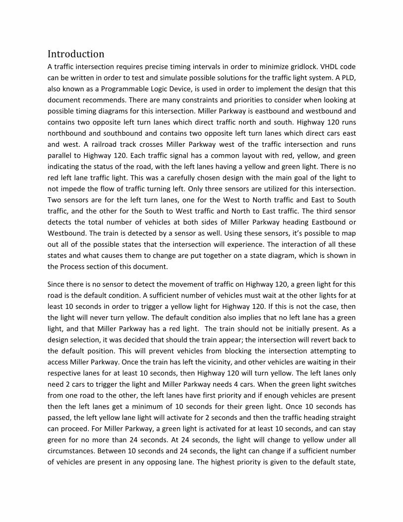
Introduction
A traffic intersection requires precise timing intervals in order to minimize gridlock. VHDL code
can be written in order to test and simulate possible solutions for the traffic light system. A PLD,
also known as a Programmable Logic Device, is used in order to implement the design that this
document recommends. There are many constraints and priorities to consider when looking at
possible timing diagrams for this intersection. Miller Parkway is eastbound and westbound and
contains two opposite left turn lanes which direct traffic north and south. Highway 120 runs
northbound and southbound and contains two opposite left turn lanes which direct cars east
and west. A railroad track crosses Miller Parkway west of the traffic intersection and runs
parallel to Highway 120. Each traffic signal has a common layout with red, yellow, and green
indicating the status of the road, with the left lanes having a yellow and green light. There is no
red left lane traffic light. This was a carefully chosen design with the main goal of the light to
not impede the flow of traffic turning left. Only three sensors are utilized for this intersection.
Two sensors are for the left turn lanes, one for the West to North traffic and East to South
traffic, and the other for the South to West traffic and North to East traffic. The third sensor
detects the total number of vehicles at both sides of Miller Parkway heading Eastbound or
Westbound. The train is detected by a sensor as well. Using these sensors, it’s possible to map
out all of the possible states that the intersection will experience. The interaction of all these
states and what causes them to change are put together on a state diagram, which is shown in
the Process section of this document.
Since there is no sensor to detect the movement of traffic on Highway 120, a green light for this
road is the default condition. A sufficient number of vehicles must wait at the other lights for at
least 10 seconds in order to trigger a yellow light for Highway 120. If this is not the case, then
the light will never turn yellow. The default condition also implies that no left lane has a green
light, and that Miller Parkway has a red light. The train should not be initially present. As a
design selection, it was decided that should the train appear; the intersection will revert back to
the default position. This will prevent vehicles from blocking the intersection attempting to
access Miller Parkway. Once the train has left the vicinity, and other vehicles are waiting in their
respective lanes for at least 10 seconds, then Highway 120 will turn yellow. The left lanes only
need 2 cars to trigger the light and Miller Parkway needs 4 cars. When the green light switches
from one road to the other, the left lanes have first priority and if enough vehicles are present
then the left lanes get a minimum of 10 seconds for their green light. Once 10 seconds has
passed, the left yellow lane light will activate for 2 seconds and then the traffic heading straight
can proceed. For Miller Parkway, a green light is activated for at least 10 seconds, and can stay
green for no more than 24 seconds. At 24 seconds, the light will change to yellow under all
circumstances. Between 10 seconds and 24 seconds, the light can change if a sufficient number
of vehicles are present in any opposing lane. The highest priority is given to the default state,

followed by the left turn lanes on Miller Parkway and then Miller Parkway itself. The Highway
120 left lane is then given priority if there are a sufficient number of vehicles before the
intersection finally transitions back to the default state. The red lights wait 2 seconds until they
transition to green in order to prevent them from simply flashing once. This causes a brief
period of having all of the signals displaying red lights, which is not one of the states
constructed, but rather a side effect of holding the red lights on for a brief period of time. This
is a much safer alternative than having an immediate transition from red to green. There were
several additional design opportunities, including an emergency vehicle which could change any
light to green, and a variable timer to queue cars onto Interstate 75. Both of these optional
additions to the design were not implemented due to time constraints.
The 4 inputs as discussed previously are the 3 sensors which detect the number of vehicles
present, and the train toggle switch which detects if and how long a train is present. There are
many different outputs of this system. Each sensor has its own count display which shows the
total number of vehicles waiting. This display is consists of 3 LEDs counting in binary. Once a
green light occurs, this number is reset. It is designed so that the minimum number of cars
required will trip the lights, but the counter will continue to count up until the light changes. 5
LEDs represent each traffic signal. Red, yellow and green LEDs indicate the road status to the
vehicles waiting to go straight and yellow and green LEDs are used to indicate the status to
vehicles waiting to turn left. When Interstate 120 is red, another strobing red LED activates at 2
Hz with a duty cycle of 30%. When the train is present, two red LEDs blink in tandem at 2 Hz,
and turn off when the train is not present. The design uses two PLDs running at two different
frequencies. The first PLD is used as a timer to count the seconds to determine state transitions
and is wired to operate at 1 Hz using a 555 timer. The second PLD is used as the logic to
determine when to switch to different states. The first PLD inputs into the second PLD. The
second PLD also uses a 555 timer to operate at a much faster 590 Hz. Choosing a fast clock cycle
for the second PLD prevents delays when switching between states.
Process The original intent of the car sensors were for them to be wired up as de-bounced pushbuttons,
so that every possible state could be examined one at a time. It was decided that a much better
alternative would be to have the cars and train occur at pseudo-random times, which is more in
line with what an actual intersection experiences. In order to generate pseudo-random car
counts, a 555 timer is wired in astable mode to have a strange duty cycle percentage using
capacitors and resistors. This timer is then inputted into a NOR gate along with another 555
timer that has different capacitor and resistor values with a different duty cycle. The output of
this gate feeds into the counter so that when both 555 timers give off a low voltage a car is
detected. The capacitors are very cheap, and because of this, the output is not perfectly
repeatable and tends to drift. This means that after an entire period has elapsed, the same

output will not occur at the exact same time. It will either be a few seconds ahead or behind.
This behavior was confirmed by using a stop watch and comparing when the counter should
count versus when it actually does. Normally a cheap capacitor will negatively affect the overall
output of the circuit, but this design benefits from having a 555 timer that is not predictable.
The strobing red light to indicate a Red light on Highway 120 is required to have a duty cycle of
30%. Unfortunately, the basic duty cycle equation can only provide a solution to a duty cycle
between 50% and 100%. There are many ways to get a low duty cycle, such as using a PNP
transistor, but the simplest method was to generate a 70% duty cycle and then use a
SN74ACT04N inverter chip to invert the output to obtain a duty cycle of around 30%. The three
equations listed are used in order to find the necessary period, frequency, and duty cycle of
each 555 timer.
(1)
(2)
(3)
R1 is the resistor that connects Pin 7 of the 555 timer to Vcc. R2 is the resistor value that
connects Pin 6 to Pin 7. C is the capacitor that connects Pin 2 to GND. Table 1 lists all of the
pertinent information related to every 555 timer used in the design layout. It is also used as an
alternative to having to list every resistor and capacitor value on the schematic.

Table 1- Data for each 555 Timer
Values Strobing Hwy 120 Red Light
Railroad Crossing Timer 1
Railroad Crossing Timer 2
1 Hz PLD
590 Hz PLD
Hwy 120 Left Timer 1
Hwy 120 Left Timer 2
Miller Pkwy Timer 1
Miller Pkwy Timer 2
Miller Left Timer 1
Miller Left Timer 2
Resistor 1 220 KΩ 180 KΩ --------- 4.7 KΩ 15 KΩ 39 KΩ 1000 KΩ
1 KΩ 1 KΩ 180 KΩ 22 KΩ
Resistor 2 220 KΩ 68 KΩ --------- 150 KΩ
4.7 KΩ 10 KΩ 330 KΩ 470 KΩ 470 KΩ 56 KΩ 220 KΩ
Capacitor 1 µF 220 µF 10 µF 4.7 µF 0.1 µF 330 µF 10 µF 33 µF 10 µF 47 µF 47 µF
Output High
(seconds)
0.30492 37.81 --------- 0.5038 0.00136 11.205 9.2168 10.771 3.2640 7.686 7.8821
Output Low
(seconds)
0.15245 10.367 --------- 0.4885 0.0003 2.2868 2.2868 10.748 3.2571 1.82397 7.1656
Total Period
(seconds)
0.45737 48.1773 --------- 0.9924 0.00169 13.49 11.503 21.519 6.521 9.5107 15.047
Frequency (Hz)
2.181818 0.0207 --------- 1.0055 590.163 0.07395 0.08674 0.04637 0.15302 0.1049 0.0663
Duty Cycle (%High)
66.666 78.481 --------- 50.771 80.7377 83.0508 80.1204 50.0531 50.0531 80.821 52.3809
Table 1 shows the breakdown of all of the timers in the circuit. Railroad Crossing Timer 2 is not
used to detect a train; instead it is used to control the railroad crossing lights. This is why no
resistors are used, and as seen in the schematic, this timer is no connected to Vcc directly.
Many of the timers have a large duty cycle percentage. This is to prevent them from going high
often when NORed together. The values shown in the column for the strobing Highway 120 red
light are before they are connected to an inverter, so it looks like the duty cycle appears
incorrect but that is not the case. It does act as intended when placed with the red LED.
The 74x191 4 bit synchronous up/down binary counters are useful for counting the number of
vehicles waiting at the light. When it receives a pulse from the NOR gate, it increments the
value by 1. This value will continue increasing until it is reset by a green light. It is able to count
up to 15, but this value should never reach that high under normal traffic circumstances. The
schematic on page 8 goes into great detail about the pin out of each chip. The values of the
capacitors and resistors can be found on Table 1. The PLDs are not shown connected to
anything, and the traffic light LEDs are not showing. This is because of several fatal errors from
the programming side of this project which will be discussed later on in this report. The LEDs
are color coded to help differentiate the sub-circuits, and a picture of the entire layout of the
project will be available in the Appendix section of this report.
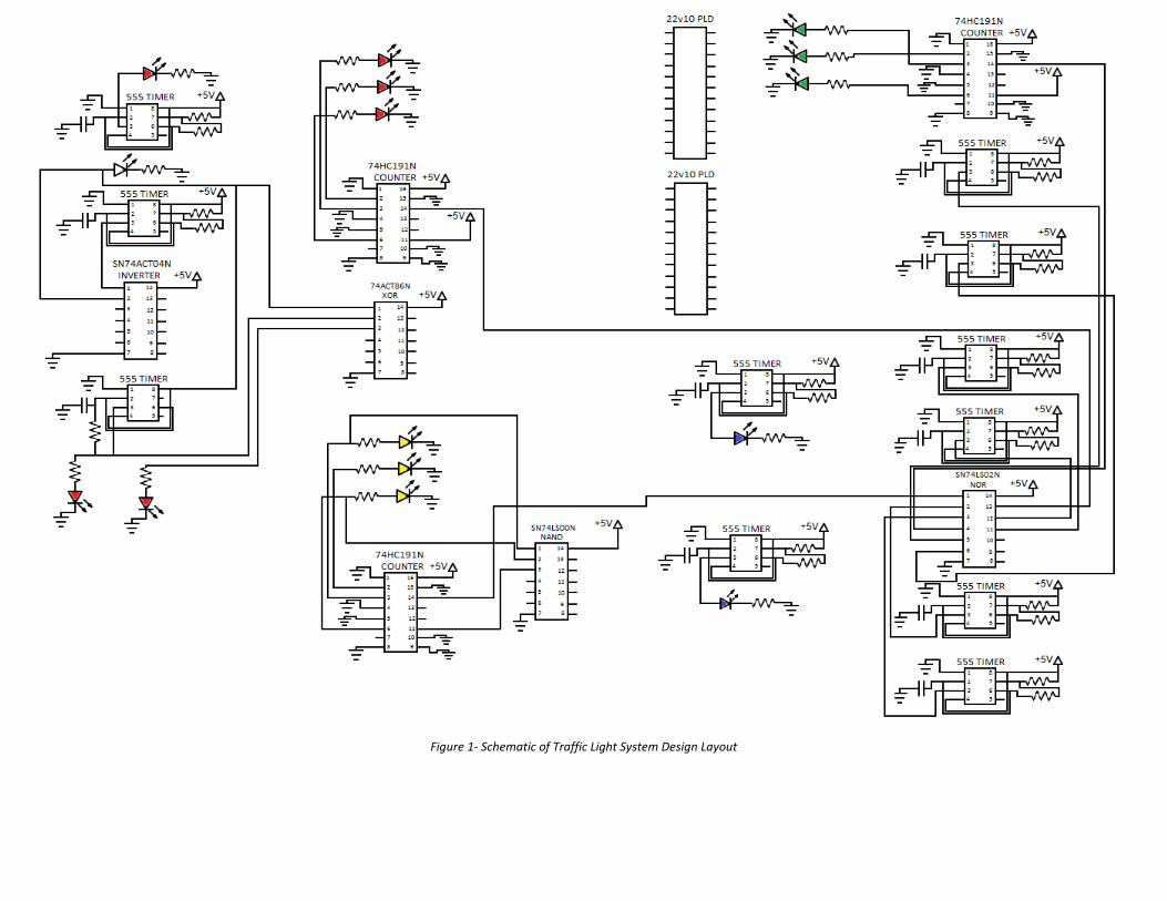
Figure 1- Schematic of Traffic Light System Design Layout

In order to program the PLDs and provide the necessary solutions for the conditions and
priority ranks of the traffic lights, 10 states were created. These states, and the paths between
them, account for every possible situation for the traffic intersection. The names of the 10
states are: GNS, YNS, RNS, LGEW, LYEW, GEW, YEW, REW, LGNS, and LYNS. The inputs for each
of these states are: SEW, LSNS, LSEW, TRAIN, 14s, 10s, and 2s. The inputs are shortened and
their expanded names are as follows: SEW= Sensor East West, LSNS= Left Sensor North South,
LSEW= Left Sensor East West and TRAIN = Train is at intersection. The other inputs are time
inputs. The state diagram is constructed in Figure 2, and the transition table is constructed in
Figure 3. These are extremely useful because not only do they help with the coding aspect of
the project, but they can also reveal when conflicting or missing conditions and states might
occur.
Figure 2- State Machine
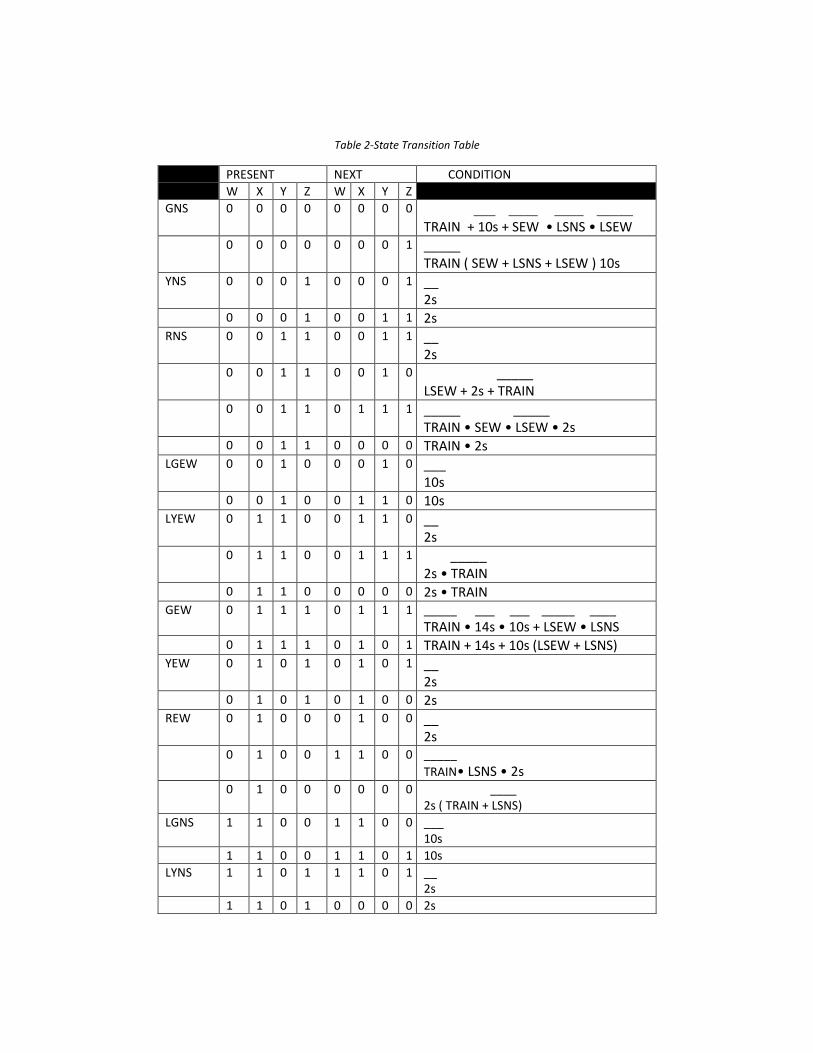
Table 2-State Transition Table
PRESENT NEXT CONDITION
W X Y Z W X Y Z
GNS 0 0 0 0 0 0 0 0 ___ ____ ____ _____ TRAIN + 10s + SEW • LSNS • LSEW
0 0 0 0 0 0 0 1 _____ TRAIN ( SEW + LSNS + LSEW ) 10s
YNS 0 0 0 1 0 0 0 1 __ 2s
0 0 0 1 0 0 1 1 2s RNS 0 0 1 1 0 0 1 1 __
2s 0 0 1 1 0 0 1 0 _____
LSEW + 2s + TRAIN 0 0 1 1 0 1 1 1 _____ _____
TRAIN • SEW • LSEW • 2s 0 0 1 1 0 0 0 0 TRAIN • 2s LGEW 0 0 1 0 0 0 1 0 ___
10s 0 0 1 0 0 1 1 0 10s LYEW 0 1 1 0 0 1 1 0 __
2s 0 1 1 0 0 1 1 1 _____
2s • TRAIN 0 1 1 0 0 0 0 0 2s • TRAIN GEW 0 1 1 1 0 1 1 1 _____ ___ ___ _____ ____
TRAIN • 14s • 10s + LSEW • LSNS 0 1 1 1 0 1 0 1 TRAIN + 14s + 10s (LSEW + LSNS) YEW 0 1 0 1 0 1 0 1 __
2s
0 1 0 1 0 1 0 0 2s
REW 0 1 0 0 0 1 0 0 __ 2s
0 1 0 0 1 1 0 0 _____
TRAIN• LSNS • 2s 0 1 0 0 0 0 0 0 ____
2s ( TRAIN + LSNS)
LGNS 1 1 0 0 1 1 0 0 ___ 10s
1 1 0 0 1 1 0 1 10s
LYNS 1 1 0 1 1 1 0 1 __ 2s
1 1 0 1 0 0 0 0 2s
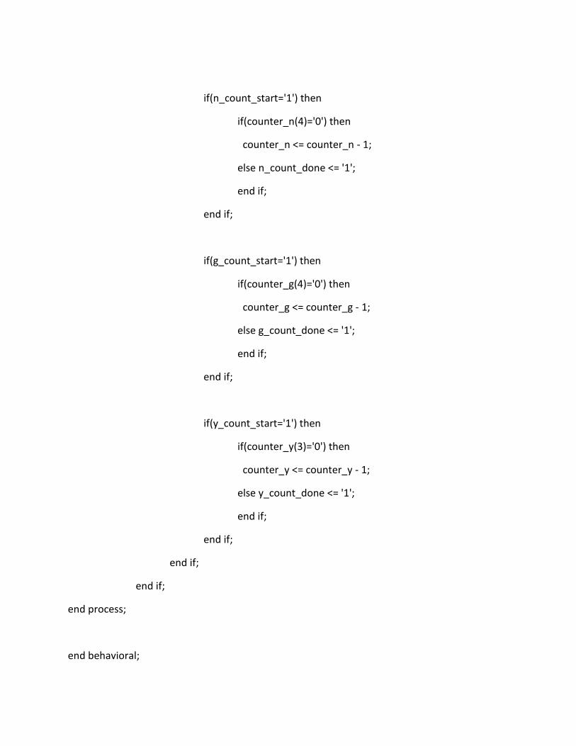
Coding For the implementation of the system, two PLDs were used. One PLD controlled the timing of
each sensor and the other controlled the state machine. The reason for the use of two PLDs
was to ease the load on any single chip and to make sure that enough inputs and outputs were
available.
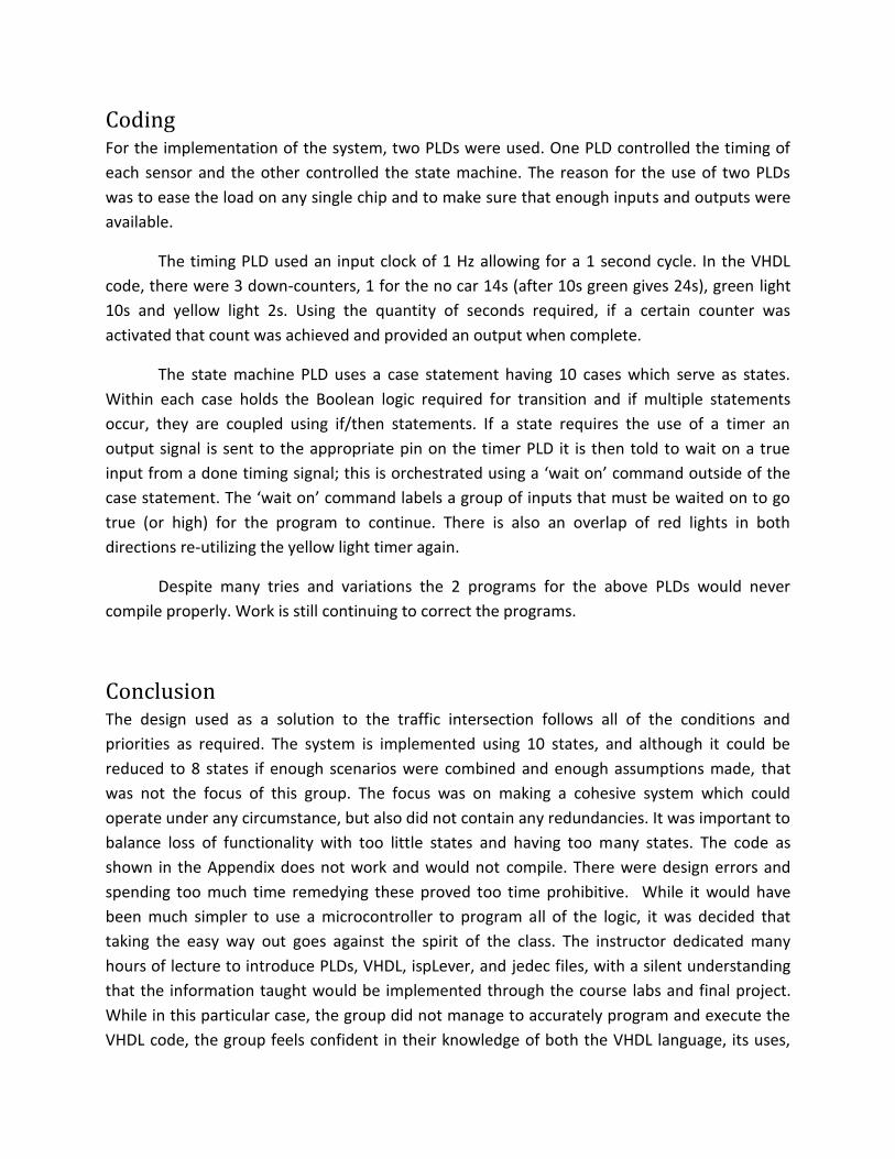
The timing PLD used an input clock of 1 Hz allowing for a 1 second cycle. In the VHDL
code, there were 3 down-counters, 1 for the no car 14s (after 10s green gives 24s), green light
10s and yellow light 2s. Using the quantity of seconds required, if a certain counter was
activated that count was achieved and provided an output when complete.
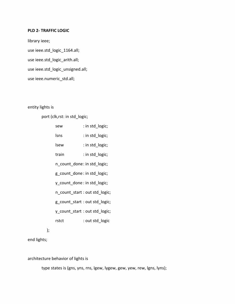
The state machine PLD uses a case statement having 10 cases which serve as states.
Within each case holds the Boolean logic required for transition and if multiple statements
occur, they are coupled using if/then statements. If a state requires the use of a timer an
output signal is sent to the appropriate pin on the timer PLD it is then told to wait on a true
input from a done timing signal; this is orchestrated using a ‘wait on’ command outside of the
case statement. The ‘wait on’ command labels a group of inputs that must be waited on to go
true (or high) for the program to continue. There is also an overlap of red lights in both
directions re-utilizing the yellow light timer again.
Despite many tries and variations the 2 programs for the above PLDs would never
compile properly. Work is still continuing to correct the programs.
Conclusion The design used as a solution to the traffic intersection follows all of the conditions and
priorities as required. The system is implemented using 10 states, and although it could be
reduced to 8 states if enough scenarios were combined and enough assumptions made, that
was not the focus of this group. The focus was on making a cohesive system which could
operate under any circumstance, but also did not contain any redundancies. It was important to
balance loss of functionality with too little states and having too many states. The code as
shown in the Appendix does not work and would not compile. There were design errors and
spending too much time remedying these proved too time prohibitive. While it would have
been much simpler to use a microcontroller to program all of the logic, it was decided that
taking the easy way out goes against the spirit of the class. The instructor dedicated many
hours of lecture to introduce PLDs, VHDL, ispLever, and jedec files, with a silent understanding
that the information taught would be implemented through the course labs and final project.
While in this particular case, the group did not manage to accurately program and execute the
VHDL code, the group feels confident in their knowledge of both the VHDL language, its uses,

and the circuitry components used to implement the code onto a breadboard. As demonstrated
thoroughly throughout this paper, the group has shown mastery of 555 timers, counters, and
many other gates first introduced in this course. With two properly coded PLDs, this system
would be able to accurately reflect the conditions and priorities laid forth. It is understood that
the time required to complete this task has been drastically reduced, and this group is proud to
submit both the code written and the circuit that was made in this time period. Given more
time to practice with the code, it is with a firm belief that the project can be demonstrated
successfully above and beyond what the minimum success criteria calls for.

Appendix
VHDL CODE
PLD 1 – TIMING
library ieee;
use ieee.std_logic_1164.all;
use ieee.std_logic_arith.all;
use ieee.std_logic_unsigned.all;
use ieee.numeric_std.all;
use IEEE.std_logic_unsigned.all;
entity counter is
port(
clk : in std_logic;
rstct : in std_logic;
n_count_start : in std_logic;
g_count_start : in std_logic;
y_count_start : in std_logic;
n_count_done : out std_logic;
g_count_done : out std_logic;
y_count_done : out std_logic
);
end;
architecture behavioral of counter is

--signal definitions--
--counter signals--initial values--
constant n_count : unsigned(3 downto 0) := x"E";
constant g_count : unsigned(3 downto 0) := x"A";
constant y_count : unsigned(3 downto 0) := x"2";
signal counter_n : unsigned(4 downto 0);
signal counter_g : unsigned(4 downto 0);
signal counter_y : unsigned(4 downto 0);
begin
--counter process--
---counts down from initial value and outputs when done.---
process(rstct,clk,counter_n,counter_g,counter_y)
begin
if(rising_edge(clk)) then
if(rstct='1') then
counter_n <= '0' & n_count;
counter_g <= '0' & g_count;
counter_y <= '0' & y_count;
else
if(n_count_start='1') then
if(counter_n(4)='0') then
counter_n <= counter_n - 1;
else n_count_done <= '1';
end if;
end if;
if(g_count_start='1') then
if(counter_g(4)='0') then
counter_g <= counter_g - 1;
else g_count_done <= '1';
end if;
end if;
if(y_count_start='1') then
if(counter_y(3)='0') then
counter_y <= counter_y - 1;
else y_count_done <= '1';
end if;
end if;
end if;
end if;
end process;
end behavioral;
PLD 2- TRAFFIC LOGIC
library ieee;
use ieee.std_logic_1164.all;
use ieee.std_logic_arith.all;
use ieee.std_logic_unsigned.all;
use ieee.numeric_std.all;
entity lights is
port (clk,rst: in std_logic;
sew : in std_logic;
lsns : in std_logic;
lsew : in std_logic;
train : in std_logic;
n_count_done : in std_logic;
g_count_done : in std_logic;
y_count_done : in std_logic;
n_count_start : out std_logic;
g_count_start : out std_logic;
y_count_start : out std_logic;
rstct : out std_logic
);
end lights;
architecture behavior of lights is
type states is (gns, yns, rns, lgew, lygew, gew, yew, rew, lgns, lyns);

signal pstate, nstate: states;
begin
process --(rst, clk, pstate, nstate, sew, lsns, lsew, train, n_count_done, g_count_done, y_count_done )
begin
if rst = '1' then
pstate<= gns;
elsif rising_edge(clk) then
pstate <= nstate;
end if;
case pstate is
when gns =>
rstct <= '1';
g_count_start <= '1';
wait until sew or lsns or lsew;
if train or not g_count_done or not sew and not lsns and not lsew then
nstate <= gns;
elsif not train and g_count_done and sew or not train and g_count_done and lsns or not train and g_count_done and lsew then
nstate <= yns;
else nstate <= gns;
end if;
when yns =>
rstct <= '1';
y_count_start <= '1';

wait until y_count_done;
if not y_count_done then
nstate <= yns;
elsif y_count_done then
nstate <= rns;
else nstate <= yns;
end if;
when rns =>
rstct <= '1';
y_count_start <= '1';
wait until y_count_done;
if not y_count_done then
nstate <= rns;
elsif lsew or y_count_done or not train then
nstate <= lgew;
elsif not train and sew and not lsew and y_count_done then
nstate <= gew;
elsif train and y_count_done then nstate <= gns;
else nstate <= rns;
end if;
when lgew =>
rstct <= '1';
g_count_start <= '1';
wait until g_count_done;
if not g_count_done then
nstate <= lgew;

elsif g_count_done then
nstate <= lyew;
else nstate <= lgew;
end if;
when lyew =>
rstct <= '1';
y_count_start <= '1';
wait until y_count_done;
if not y_count_done then
nstate <= lyew;
elsif y_count_done and not train then
nstate <= gew;
elsif y_count_done and train then
nstate <= gns;
else nstate <= lyew;
end if;
when gew =>
rstct <= '1';
g_count_start <= '1';
n_count_start <= '1';
wait until g_count_done;
if not train and not n_count_done and not g_count_done or not lsew and not lsns then
nstate <= gew;
elsif train or n_count_done or g_count_done and lsew or g_count_done and lsns then
nstate <= yew;
else nstate <= gew;
end if;
when yew =>
rstct <= '1';
y_count_start <= '1';
wait until y_count_done;
if not y_count_done then
nstate <= yew;
elsif y_count_done then
nstate <= rew;
else nstate <= yew;
end if;
when rew =>
rstct <= '1';
y_count_start <= '1';
wait until y_count_done;
if not y_count_done then
nstate <= rew;
elsif y_count_done and not train and lsns then
nstate <= lgns;
elsif y_count_done and train or y_count_done and not lsns then
nstate <= gns;
else nstate <= rew;
end if;
when lgns =>
rstct <= '1';
g_count_start <= '1';
wait until g_count_done;
if not g_count_done then
nstate <= lgns;
elsif g_count_done then
nstate <= lyns;
else nstate <= lgns;
end if;
when lyns =>
rstct <= '1';
y_count_start <= '1';
wait until y_count_done;
if not y_count_done then
nstate <= lyns;
elsif y_count_done then
nstate <= gns;
else nstate <= lyns;
end if;
end case;
wait on rst, clk, pstate, nstate, sew, lsns, lsew, train, n_count_done, g_count_done, y_count_done;
end process;
end behavior;
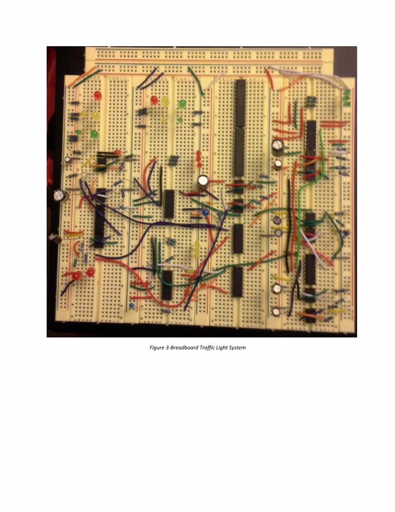
Figure 3-Breadboard Traffic Light System