Complex Detector Electronics: FPGA’s & ASIC’s
11
© DJMorrissey, 2oo9 Complex Detector Electronics: FPGA’s & ASIC’s FPGA’s ... the manufacturer http://www.xilinx.com/ NRE’s – non-recurring engineering costs TTM – time to market http://www.tutorial-reports.com/computer-science Complex systems and experiments with very high channel counts need to make a large number of logical decisions rapidly. Options for “electronic decision makers” include: a microprocessor (in CAMAC or VME), a field-programmable gate-array (FPGA), or an application-specific integrated-circuit (ASIC). ASIC’s … the website: http://www-ee.eng.hawaii.edu/~msmith/ASICs/HTML/ASICs.htm High Low
Transcript of Complex Detector Electronics: FPGA’s & ASIC’s

© DJMorrissey, 2oo9
Complex Detector Electronics: FPGA’s & ASIC’s
FPGA’s ... the manufacturer http://www.xilinx.com/
NRE’s – non-recurring engineering costs TTM – time to market
http://www.tutorial-reports.com/computer-science
Complex systems and experiments with very high channel counts need to make a large number of logical decisions rapidly. Options for “electronic decision makers” include: a microprocessor (in CAMAC or VME), a field-programmable gate-array (FPGA), or an application-specific integrated-circuit (ASIC).
ASIC’s … the website: http://www-ee.eng.hawaii.edu/~msmith/ASICs/HTML/ASICs.htm
High
Low
© DJMorrissey, 2oo9
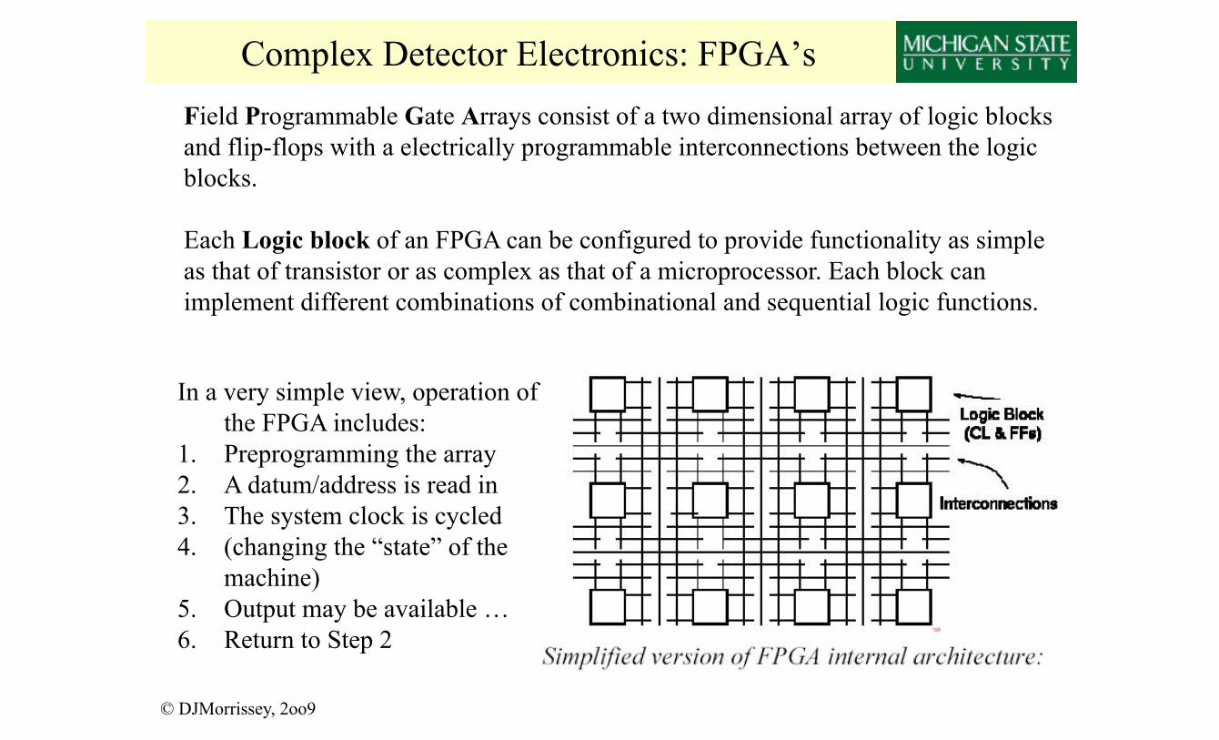
Complex Detector Electronics: FPGA’s Field Programmable Gate Arrays consist of a two dimensional array of logic blocks and flip-flops with a electrically programmable interconnections between the logic blocks.
Each Logic block of an FPGA can be configured to provide functionality as simple as that of transistor or as complex as that of a microprocessor. Each block can implement different combinations of combinational and sequential logic functions.
In a very simple view, operation of the FPGA includes:
1. Preprogramming the array 2. A datum/address is read in 3. The system clock is cycled 4. (changing the “state” of the
machine) 5. Output may be available … 6. Return to Step 2

© DJMorrissey, 2oo9
Complex Detector Electronics: FPGA’s
Jtec XLM72 is a universal logic VME module using a FPGA executing fast synchronous and combinatorial logic, a 900-MFlops/s floating-point Digital Signal Processor (DSP) executing complex numerical calculations, two 2-Mbyte banks of fast memory, and 72 ECL I/O ports.
LeCroy 2366 is a CAMAC-based logic module with 59 ECL lines and a Xilinx 4005 FPGA chip. Any logic that can be implemented as a synchronous (clocked) state machine may be programmed, subject only to the limitations of the size of the Xilinx gate array chip (approximately 5000 gates).
Field Programmable Gate Arrays can be found in CAMAC and VME packages … the programming is done externally (generally with a simulation code running on a PC) and the result has to be loaded over the backplane.

© DJMorrissey, 2oo9
Complex Detector Electronics: HiRA Example
• 20 Telescopes • 62.3 x 62.3 mm2 Active Area • strip pitch 1.8 mm • 1024 Pixels per telescope
4x CsI(Tl) 4cm
32 strips v. (front) Beam
Si-ΔE 65 µm
32 strips v (front)
Si-E 1.5 mm
pixel
32 strips h. (back)

© DJMorrissey, 2oo9
Complex Detector Electronics: HiRA ASIC
4 Ch prototype
16 Ch Production Chip
Developed at Washington University (St. Louis) and Southern Illinois University, this chip board
(differential signal output) + one VME module (SIS 14-bit sampling ADC) replaces 64 pre-amp’s, 32
Shapers, 32 TDCs and 32 ADCs
• Input is switchable, charge-sensitive [x1, 100 MeV(Si), x500MeV(Si)] • Shaper x1 with 1µs shaping time • Time-to-voltage signal against “stop” signal [150 ns, 1.5µs FS] • Both outputs are held for external sampling by flash ADC
Test by M.Wallace showed 50 keV resolution for 228Th source …

Complex Detector Electronics: MUST2
© DJMorrissey, 2oo9
• 100 cm2 area on front face • 288 channels of Energy and Time (each) • Si 300 µm / Si(Li) 5mm / CsI 4cm

Complex Detector Electronics: MUST2
© DJMorrissey, 2oo9

© DJMorrissey, 2oo9
Complex Detector Electronics: PPAC’s ?
←Q
1
Q
2 →
Conventional: resistor chain, two linear channels Problems with small signals, large size – many resistors
STAR Front-End Electronics (134k channels) http://arxiv.org/abs/nucl-ex/0205014 And http://www.star.bnl.gov/public/fee/fee.html

© DJMorrissey, 2oo9
Complex Detector Electronics: ASIC’s

© DJMorrissey, 2oo9
Complex Detector Electronics: CRDC Pads
Schematic diagram of Cathode-Readout Drift-Chamber used in Sweeper & S800 focal plane detectors
(C.Freigang, MSU thesis, 2oo1)

© DJMorrissey, 2oo9
Chap. 18 – Data Acquisition: Question What are the values of the full-scale voltage and the average conversion time of the (12-bit, 2mV LSB) ADC that is part of the STAR-FEE card?