COMPLEX 3D BIM - LiDARmaglidarmag.com/PDF/LiDARMagazine_Corbley-Complex3DBIM_Vol5No7.… · Complex...
6
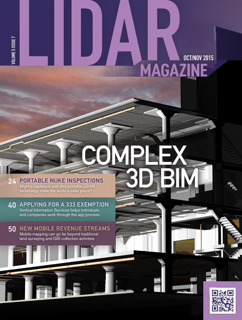
COMPLEX 3D BIM VOLUME 5 ISSUE 7 OCT/NOV 2015 APPLYING FOR A 333 EXEMPTION Might a backpack and ultra-portable LIDAR technology make the world a safer place? Vertical Information Services helps individuals and companies work through the app process Mobile mapping can go far beyond traditional land surveying and GIS collection activities NEW MOBILE REVENUE STREAMS 24 40 50 PORTABLE NUKE INSPECTIONS
Transcript of COMPLEX 3D BIM - LiDARmaglidarmag.com/PDF/LiDARMagazine_Corbley-Complex3DBIM_Vol5No7.… · Complex...
COMPLEX 3D BIM
VOLU
ME 5
ISSU
E 7
OCT/NOV 2015
APPLYING FOR A 333 EXEMPTION
Might a backpack and ultra-portable LIDAR technology make the world a safer place?
Vertical Information Services helps individualsand companies work through the app process
Mobile mapping can go far beyond traditionalland surveying and GIS collection activities
NEW MOBILE REVENUE STREAMS
24
40
50
PORTABLE NUKE INSPECTIONS
Complex 3D BIM Project Requires Mix of Cutting-Edge Technologies
BY KEVIN P. CORBLEY
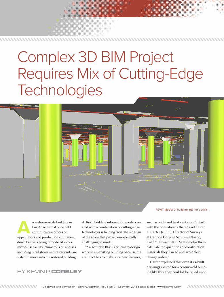
REVIT Model of building interior details.
A warehouse-style building in Los Angeles that once held administrative offices on
upper floors and production equipment down below is being remodeled into a mixed-use facility. Numerous businesses including retail stores and restaurants are slated to move into the restored building.
A Revit building information model cre-ated with a combination of cutting-edge technologies is helping facilitate redesign of the space that proved unexpectedly challenging to model.
“An accurate BIM is crucial to design work in an existing building because the architect has to make sure new features,
such as walls and heat vents, don’t clash with the ones already there,” said Lester E. Carter Jr., PLS, Director of Surveys at Cannon Corp. in San Luis Obispo, Calif. “The as-built BIM also helps them calculate the quantities of construction materials they’ll need and avoid field change orders.”
Carter explained that even if as-built drawings existed for a century-old build-ing like this, they couldn’t be relied upon
Displayed with permission • LiDAR Magazine • Vol. 5 No. 7 • Copyright 2015 Spatial Media • www.lidarmag.com
by an architect for the interior redesign. Such paper documents are notoriously inaccurate either because they were made from manual measurements or they don’t represent the myriad changes made to the building over time, such as modernization of HVAC and electrical equipment and movement of non-weight bearing walls.
The project designer, Del Amo of Torrance, Calif., hired Cannon to scan the interior of the building and provide a 3D BIM containing architectural, structural and MEP features. Specifically, they wanted as-built details for floors,
walls, ceilings, support columns and beams, stair wells and existing electrical conduits and water and fire sprinkler piping.
In preparation for the project, the interior was gutted down to the bare structural elements—walls, ceilings
and floors, as well as concrete columns that bore much of the interior building weight. Most of the HVAC runs and electrical lines remained in place. Total area to be modeled was 150,000 square feet in the basement, three above-ground floors and a roof level.
“Normally an empty building is easier to work in to conduct the scanning because the laser scanners don’t have to be set up as many times to capture the wide-open space as they would if dozens of smaller rooms had to be scanned separately,” said Carter.
But upon visiting the site during a planning visit, Cannon personnel found two features that would add significant challenge to their work.
“The concrete floors [in the basement and first level] were not flat—there
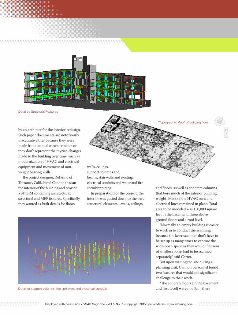
Detailed Structural Features
“Topographic Map” of building floor.
Detail of support columns, fire sprinkers and electrical conduits
Displayed with permission • LiDAR Magazine • Vol. 5 No. 7 • Copyright 2015 Spatial Media • www.lidarmag.com
were raised areas and then slopes down, almost like the floor was purposely tiered to provide platforms for some type of processing equipment or storage tanks,” said Carter.
He speculated the floor was designed that way for a reason. Perhaps the production equipment was placed on the raised surfaces so that fluid spills would drain away quickly. Or maybe the sloping floor and apparent ‘pathways’ made it easier to cart away loads of product. Whatever the reason, the cement floor had its own topography that would have to be modeled in detail for the architect to take into account.
“The cement floors sloped as much as 0.2 inches to 12 inches in some areas,” said Carter. “The designers needed an as-built model of the floor surface accurate to within 3/8 of an inch to design the interior construction of the building.”
The other odd features were the concrete supports on every level but the roof. These floor-to-ceiling columns or pillars varied in shape throughout the building, likely because they were
installed decades apart. Most were cylindrical, but others were faceted in hexagonal shapes. All changed their shape near the ceilings where they enlarged and became mostly faceted squares. Their shapes during this transition from cylinder or hexagonal to square was impossible to classify as a common geometric feature.
“We knew that we would have to use a combination of automated and manual technologies to create accurate BIMs there,” said Zoltan Nagy, Senior Project Designer at Cannon.
Scanning the InteriorCannon was an earliy adopter of using terrestrial laser scanners for as-built modeling work, having bought its first scanners nearly eight years ago. In preparation for the scan work, the team established horizontal and vertical control around the exterior of the build-ing. Total stations were used to shoot in to multiple control points on each level from outside the building. Temporary swivel scan targets on tripods were set
up on pre-selected points inside the building to register the scans to the survey control network.
“We set up the control point network to ultimately achieve a plus-or-minus 3/8-inch accuracy in the final positions of the features in the BIM,” said Carter. “Had a higher accuracy been required, we would have established a denser control network, with more measure-ment redundancy.”
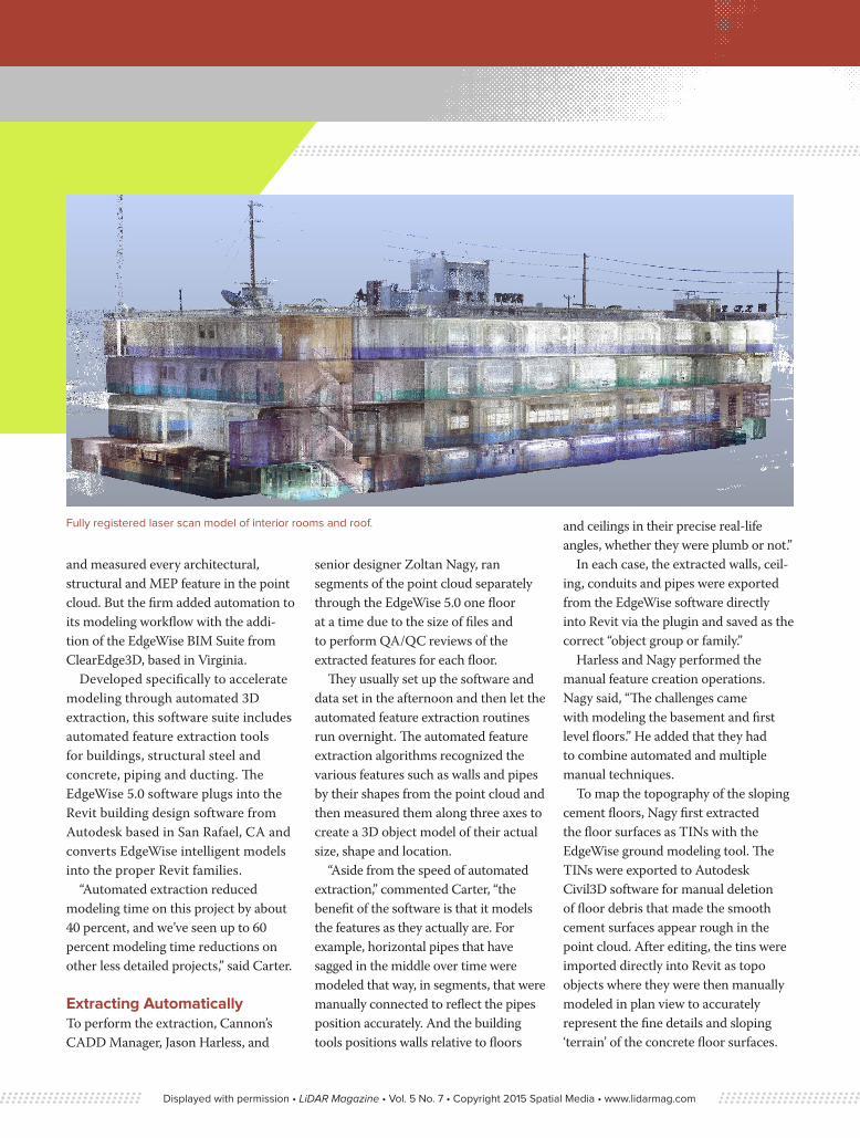
Over a period of seven days, the Cannon team used FARO Focus 3D X-330 laser scanner to capture a total of 152 scans for the basement, first through third floors and roof level. A built-in digital camera took 360-degree panoramic color photos as the scans were acquired from each setup position.
Working in FARO Scene software, the technicians performed cloud-to-cloud registration of the point clouds on each floor and then locked these scan clusters to the control points. This created a fully registered point cloud for the entire building. Before proceeding, they quality checked the point cloud against the photos to ensure there were no gaps in the scans. They also compared the cloud to spot surveys of interior features and direct dimension measurements to make sure the desired accuracy had been achieved.
Once the cloud registration and QC were completed, Cannon moved into the feature extraction and modeling phase of the project using the Edgewise software. Up until about three years ago, Cannon’s CAD designers and techni-cians would have manually identified
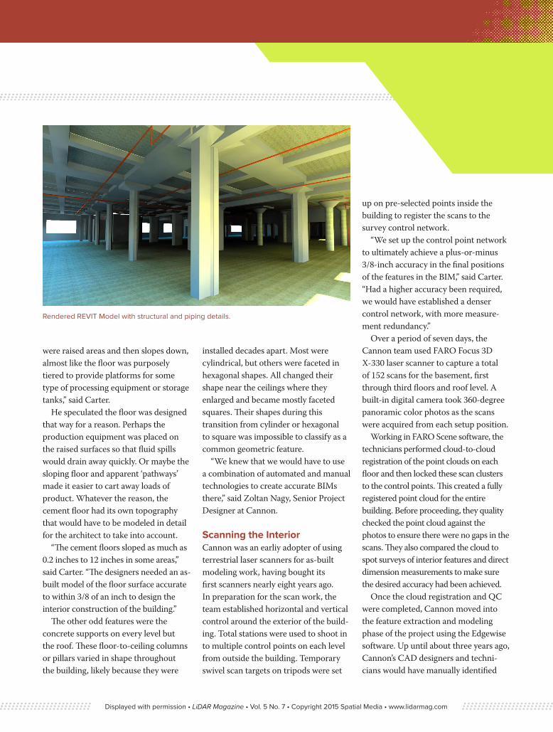
Rendered REVIT Model with structural and piping details.
Displayed with permission • LiDAR Magazine • Vol. 5 No. 7 • Copyright 2015 Spatial Media • www.lidarmag.com
and measured every architectural, structural and MEP feature in the point cloud. But the firm added automation to its modeling workflow with the addi-tion of the EdgeWise BIM Suite from ClearEdge3D, based in Virginia.
Developed specifically to accelerate modeling through automated 3D extraction, this software suite includes automated feature extraction tools for buildings, structural steel and concrete, piping and ducting. The EdgeWise 5.0 software plugs into the Revit building design software from Autodesk based in San Rafael, CA and converts EdgeWise intelligent models into the proper Revit families.
“Automated extraction reduced modeling time on this project by about 40 percent, and we’ve seen up to 60 percent modeling time reductions on other less detailed projects,” said Carter.
Extracting AutomaticallyTo perform the extraction, Cannon’s CADD Manager, Jason Harless, and
senior designer Zoltan Nagy, ran segments of the point cloud separately through the EdgeWise 5.0 one floor at a time due to the size of files and to perform QA/QC reviews of the extracted features for each floor.
They usually set up the software and data set in the afternoon and then let the automated feature extraction routines run overnight. The automated feature extraction algorithms recognized the various features such as walls and pipes by their shapes from the point cloud and then measured them along three axes to create a 3D object model of their actual size, shape and location.
“Aside from the speed of automated extraction,” commented Carter, “the benefit of the software is that it models the features as they actually are. For example, horizontal pipes that have sagged in the middle over time were modeled that way, in segments, that were manually connected to reflect the pipes position accurately. And the building tools positions walls relative to floors
and ceilings in their precise real-life angles, whether they were plumb or not.”
In each case, the extracted walls, ceil-ing, conduits and pipes were exported from the EdgeWise software directly into Revit via the plugin and saved as the correct “object group or family.”
Harless and Nagy performed the manual feature creation operations. Nagy said, “The challenges came with modeling the basement and first level floors.” He added that they had to combine automated and multiple manual techniques.
To map the topography of the sloping cement floors, Nagy first extracted the floor surfaces as TINs with the EdgeWise ground modeling tool. The TINs were exported to Autodesk Civil3D software for manual deletion of floor debris that made the smooth cement surfaces appear rough in the point cloud. After editing, the tins were imported directly into Revit as topo objects where they were then manually modeled in plan view to accurately represent the fine details and sloping ‘terrain’ of the concrete floor surfaces.
Fully registered laser scan model of interior rooms and roof.
Displayed with permission • LiDAR Magazine • Vol. 5 No. 7 • Copyright 2015 Spatial Media • www.lidarmag.com

“Viewing the TINs in plan view provided us rich information in Revit to accurately model the floors to create accurate floor surface models,” said Nagy. “We could have exported them as ‘floor objects’ from EdgeWise to Revit, but saving them as ‘topo objects’ was faster.”
The next challenge was the vertical support columns that had varying shapes. Nagy first considered extracting the cylindrical columns using the EdgeWise pipe modeling tools which Cannon routinely uses to model pipe cylinders, but he noted that the columns would have then been imported into Revit as pipe objects, requiring extensive editing. Instead, he found it was quicker to manually extract and model the columns directly in Revit.
The hexagonal and square columns, however, could be handled with the automated EdgeWise tools due to their regular geometric shapes. They were
extracted and then imported as ‘wall’ objects into Revit for editing. The tops of both types of columns, where they met the ceiling in odd patterns, had to be modeled manually in Revit.
Accuracy Standards MetAlthough Cannon encountered numerous challenges for creating the custom floor and column models, by using Edgewise
the 3D Revit Model was finished and delivered to the design firm on time.
“We performed multiple reviews and compared the detailed columns and other features to the full-color point cloud, the 360° photos and the direct QC measurements. The results were outstanding,” said Carter.
With the delivery of final Revit BIM files to the Architectural and Design-Build Team, Cannon fulfilled its commitment to Del Amo Construction that the 3D model of the interior floor surfaces, piping and conduit details, walls, ceilings and support columns would achieve an accuracy of within plus-or-minus 3/8 inch.
Cannon’s efforts provided a compre-hensive and accurate 3D as-built model containing all of the relevant features needed to design, engineer and entirely re-purpose and renovate the interior of the existing building.
Kevin Corbley is a business consultant in the geospatial industry. He may be reached through www.corbleycommunications.com.
360° color photos from FARO x330 scanner.
Completed REVIT 3D As-Built Model.
Displayed with permission • LiDAR Magazine • Vol. 5 No. 7 • Copyright 2015 Spatial Media • www.lidarmag.com