Complete Train Control
119
C T C omplete rain ontrol Digitrax, Inc. 2443 Transmitter Road Panama City, Florida USA 32404 (850) 872-9890 Fax (850) 872-9557 www.digitrax.com Digitrax Manuals & Instructions are updated periodically. Please visit www.digitrax.com for the latest version of all manuals & for available firmware updates. This rev 2.1 manual was updated 12/09. Super Premium Digitrax Complete Train Control Starter Set Manual Includes Instructions for: DCS100 Command Station Booster DCS200 Command Station Booster DT402 SeriesThrottles Duplex Radio Operation with UR92 & DT402D Simplex Radio Operation with UR91 & DT402R Infrared Operation with UR90 & DT402 Walkaround Operation with UP5
Transcript of Complete Train Control

CTC
ompleterainontrol
Digitrax, Inc.2443 Transmitter Road
Panama City, Florida USA 32404(850) 872-9890 Fax (850) 872-9557
www.digitrax.com
Digitrax Manuals & Instructions are updated periodically.Please visit www.digitrax.com for the latest version of all
manuals & for available firmware updates.This rev 2.1 manual was updated 12/09.
Super Premium Digitrax Complete Train Control
Starter Set Manual
Includes Instructions for: DCS100 Command Station BoosterDCS200 Command Station Booster
DT402 SeriesThrottlesDuplex Radio Operation with UR92 & DT402DSimplex Radio Operation with UR91 & DT402R
Infrared Operation with UR90 & DT402Walkaround Operation with UP5

1
IntroductionCongratulations on your purchase of a Digitrax Super Chief Xtra Complete
Train Control Set!
The design of the Digitrax Complete Train Control system lets you operate
your layout the way you want to. With LocoNet you simply connect system
components to build the layout control system that you’ve always wanted! The
Digitrax system reduces and simplifies layout wiring for new layouts. If you
already have a layout, you probably won’t need to rewire to install Digitrax.
Your Super Chief Xtra Starter Set has several components:
• DCS100 is your system’s command station. It generates the
information packets that tell the decoders what to do.
• DCS100 is also a booster. Boosters receive signals from the
command station, amplify them and put them on the track along
with the power from the power supply to run the locomotives.
You can have several boosters on your layout to provide addition-
al power to run more locos.
• The DT402 or the DT402D is the throttle that comes with your
Super Chief Xtra Starter Set. Throttles are the handhelds you use
to tell the command station what you want the decoders to do.
You will probably have several throttles on your layout if you
have more than one person running trains at a time.
• A UP5 Universal Panel for memory walkaround operation or a
UR92 Duplex Radio Transceiver for duplex radio or IR operation.
• LT1 LocoNet and Decoder Tester.
• A 2’ LocoNet Cable so you can get started right away.
In addition to your Super Chief Xtra you’ll need:
• A power supply (you many be able to use one you already own)
• One or more mobile decoders for your locomotives.
This manual contains information about running your layout with infrared
and/or Duplex Radio operation. Information about simplex radio operation is
included for your convenience even though your Super Chief Xtra Set is not
available with this option.
There are many different combinations of Digitrax components that can be
used to set up a layout control system that is right for you. You can combine
Digitrax products with compatible decoders, boosters and computer software
made by other companies that build compatible equipment.
Your success with & enjoyment of our products are very important to us. After
all, this is a hobby and it is FUN!!! Please read this manual carefully before
installing your system. We have included lots of hints and operating ideas
based on our experience. If you have questions not covered by this manual
please contact your dealer or visit our web site at www.digitrax.com where the
Digitrax online Tech Support Depot is always open!

Digitrax Super Chief Xtra Starter Set ManualTable of Contents
Introduction . . . . . . . . . . . . . . . . . . . . . . . . . . . . . . . . . . . . . . . . .1
1.0 Super Chief Xtra Quick Start Guide . . . . . . . . . . . . . . . . . .71.1 Connect the DCS100 to the power supply .........................................8
1.2 Connect Your DT402 Series Throttle to the DCS100.........................8
2.0 Super Chief Xtra Quick Start Duplex Radio Operation . . .92.1 Install the UR92 ..................................................................................9
2.2 Join Your DT402D Throttle to a Duplex Group ...............................10
3.0 DT402 Installation . . . . . . . . . . . . . . . . . . . . . . . . . . . . . . .11
4.0 Additional Quick Start Basics . . . . . . . . . . . . . . . . . . . . . .124.1 DT402 Throttle Start Up ..................................................................12
4.2 DT402 Series Throttle Keyboard Layout..........................................13
4.3 DT402 Series Throttle Controls At A Glance ....................................14
4.4 Track power on and off .....................................................................15
4.5 Select and Run An Analog Loco on Address “00” ...........................16
4.6 Select and Run A Decoder Equipped Loco ......................................17
4.7 Shutting Down the System................................................................19
4.8 Resuming your session......................................................................19
4.9 Quick Start Problems?.......................................................................19
4.10 What’s Next? .................................................................................20
5.0 LocoNet: The Digitrax Difference! . . . . . . . . . . . . . . . . . .215.1 System Architecture .........................................................................21
5.2 Event Driven or Polled? ....................................................................21
5.3 Network Speed ..................................................................................22
5.4 LocoNet Personal Edition ................................................................22
5.5 LocoNet Expansion ..........................................................................22
5.6 LocoNet Wiring Components............................................................24
5.7 Making LocoNet Cables....................................................................24
5.8 Testing LocoNet Cables with an LT1................................................24
5.9 LocoNet Throttle Jacks and LocoNet Connection Jacks ..................25
5.10 Installing the Universal Panel (UP5) ..............................................25
5.10.1 Hooking up the UP/UR's Track Status Indicators (Optional) ..26
6.0 Advanced Installation of Digitrax On Your Layout . . . . .276.1 Setting Up A Programming Track.....................................................27
6.1.1 Ops mode programming .............................................................27
6.1.2 Service mode programming (Using a programming track) .......28
6.2 Direct Home Wiring vs. Common Rail Wiring ................................28
6.3 Recommended wire sizes for power bus and track feeders ..............29
6.4 Other Track Wiring Considerations ..................................................29
6.5 Layout Power Districts......................................................................29
6.5.1 Number of Locos ........................................................................30
2

6.5.2 Short Circuits ..............................................................................30
6.5.3 To set up power districts and sub-districts on your layout:........30
6.5.4 How can I be sure I have enough power to run my trains? .......30
6.6 Adding a DB150 Booster ..................................................................30
6.7 Reversing Section Wiring ................................................................31
6.8 Using a DB150 as an AutoReversing Booster ..................................32
6.9 Using PM42 for Power Management and AutoReversing................33
6.10 Using AR1 for AutoReversing ........................................................33
6.11 Using DC and DCC together on the same layout ...........................33
6.12 Troubleshooting Layout Wiring ......................................................34
7.0 DCS100/200 Control Panel . . . . . . . . . . . . . . . . . . . . . . . . .357.0.1 DCS100 and DCS200 .................................................................35
7.1 Power On Indicator ...........................................................................35
7.2 Power In Terminals ...........................................................................35
7.2.1 Power Supply..............................................................................35
7.3 PROG A and PROG B Terminals......................................................36
7.4 Ground Terminal ...............................................................................36
7.5 RAIL B and RAIL A Terminals ........................................................36
7.6 TRACK STATUS Indicator...............................................................37
7.7 LocoNet Jacks A and B .....................................................................37
7.8 SCALE Switch (O/G, N, HO) ...........................................................37
7.8.1 Track Voltage Adjustment...........................................................37
7.9 MODE Switch ...................................................................................38
7.10 OFF LINE Indicator......................................................................38
7.10.1 Heat Dissipation........................................................................38
7.10.2 Troubleshooting DCS100 Shutdowns.......................................38
7.11 CONFIG Indicator...........................................................................38
7.12 NET Indicator..................................................................................39
7.13 DCS100 Audible Sounds.................................................................40
8.0 DCS100 CMOS Battery Replacement . . . . . . . . . . . . . . . .41
9.0 Customizing Your DCS100/200--Option Switch Setup . .429.1 Changing DCS100/200 Option Switches..........................................42
9.2 DCS Option Switch Tables ...............................................................43
10.0 DT402 Series Throttle Control Panel . . . . . . . . . . . . . . .4810.1 General Information ........................................................................48
10.2 L (Left) and R (Right) Throttle Knobs............................................48
10.3 Liquid Crystal Display (LCD) .......................................................49
10.3.1 Loco Icon ..................................................................................49
10.3.2 Direction Indicators .................................................................49
10.3.4 Smoke Icon ..............................................................................49
10.3.4 Mode Indicator..........................................................................50
10.3.5 Text Area...................................................................................51
10.3.6 L (Left) and R (Right) Throttle Display ...................................52
10.3.7 L and R Bar Graph....................................................................52
3

10.3.8 Function Display.......................................................................53
10.3.9 Track Power Indicator...............................................................53
10.3.10 Tetherless Indicator.................................................................53
10.3.11 L and R Semaphores-Cab Signaling.......................................53
10.4 DT402 Keypad ................................................................................54
10.4.1 FUNC Key ................................................................................54
10.4.2 MU Key ....................................................................................54
10.4.3 LOCO Key................................................................................54
10.4.4 SWCH Key ...............................................................................54
10.4.5 L and R Reverse Keys ..............................................................54
10.4.6 Y / + and N / - Keys..................................................................55
10.4.7 DISP Key ..................................................................................55
10.4.8 PROG Key ................................................................................55
10.4.9 EDIT Key..................................................................................55
10.4.10 FIND Key ...............................................................................55
10.4.11 BACK Key..............................................................................55
10.4.12 PWR Key ................................................................................56
10.4.13 OPTN / t Key..........................................................................56
10.4.14 CLOC / c Key .........................................................................56
10.4.15 EXIT Key................................................................................56
10.4.16 ENTER Key............................................................................56
10.4.17 EMRG STOP Key...................................................................56
10.4.18 Full Numeric Keypad .............................................................57
10.4.19 Infrared Emitters .....................................................................57
11.0 How to Select and Run Trains . . . . . . . . . . . . . . . . . . . . .5811.1 Turn track power on and off............................................................58
11.2 Select and Run An Analog Loco on Address “00” .........................59
11.3 Select and Run A Decoder-Equipped Loco ....................................60
11.4 Releasing An Address From A Throttle ..........................................62
11.5 Dispatching addresses or consists ...................................................62
11.6 Recall a Loco...................................................................................63
11.7 Stealing: Forcing An Address Selection..........................................63
11.8 Slot Following .................................................................................64
11.9 “slot=max” Message........................................................................64
12.0 Stop . . . . . . . . . . . . . . . . . . . . . . . . . . . . . . . . . . . . . . . . . .6512.1 Setting A Loco to Zero Speed .........................................................65
12.2 Emergency Stop...............................................................................65
12.2.1 Local Stop-Factory Default ......................................................65
12.2.2 Global Stop-Optional Setting ...................................................65
12.2.3 Track Power Off Stop ...............................................................65
13.0 Controlling Functions . . . . . . . . . . . . . . . . . . . . . . . . . . . .6613.1 Controlling Functions F0-F12 ........................................................66
13.2 Controlling Expanded Functions F13-F19......................................67
13.3 Controlling Functions 20-28 ..........................................................68
4

13.4 Controlling Functions On Consisted Locomotives ........................68
14.0 Tetherless Operation . . . . . . . . . . . . . . . . . . . . . . . . . . . .69
14.1 General Tetherless Operations.........................................................69
14.1.1 Selecting a Locomotive-Safety Selection.................................69
14.1.2 Releasing a Locomotive Using IR or Simplex Radio ..............69
14.1.3 Multiple Unit Operations..........................................................70
14.1.4 Programming while tetherless ..................................................70
14.1.5 Switch Mode .............................................................................70
14.1.6 Ballistic Tracking......................................................................70
14.1.7 Fast Clock ................................................................................70
14.1.8 Throttle Keypad Lock ..............................................................70
14.2 Using the DT402 Series Throttle in IR Mode.................................71
14.2.1 LocoNet ID Change..................................................................72
14.2.2 Adding a new UR90, UR91 or UR92 to LocoNet ...................72
14.3 Using the DT402R in Simplex Radio Mode ..................................73
14.4 Using the DT402D Throttle in Duplex Radio Mode ......................74
14.4.1 Join a Duplex Group when operating in Duplex Radio Mode.74
14.4.2 Configuring the Duplex Group name .......................................75
14.4.3 Configuring the Duplex Group Channel (11-26) .....................76
14.4.4 Configuring the Duplex Group Password ................................76
15.0 Advanced Operations Capabilities . . . . . . . . . . . . . . . . .7715.1 Multiple Unit Operations ................................................................77
15.1.1 Adding a Locomotive To A Consist..........................................77
15.1.2 Removing A Loco From A Consist...........................................79
15.1.3 Nested Consisting .....................................................................79
15.1.4 MU of Mismatched Locomotives.............................................79
15.2 Sw (Switch) Mode ..........................................................................80
15.2.1 To change the position of a switch or turnout ..........................80
15.3 Fast Clock........................................................................................81
15.3.1 Fast Clock Basics......................................................................81
15.3.2 Stop the Fast Clock...................................................................82
15.3.3 Edit Fast Clock Time, Rate and Alarm.....................................82
15.4 Route Basics ....................................................................................83
15.4.1 Enabling Routes .......................................................................83
15.4.2 External Routes.........................................................................83
15.4.3 Edit Routes ...............................................................................84
15.5 FIND Key and Digitrax Transponding............................................86
16.0 Customizing Your Throttle - Step-by-Step . . . . . . . . . . .8716.1 Changing the Throttle Options........................................................87
17.0 Programming Configuration Variables (CVs) . . . . . . . . .9017.1 Programming Mobile Decoder Addresses ......................................91
17.2 Programming CVs Other Than Addresses ......................................93
17.3 Operations Mode Programming ......................................................94
17.4 Busy or Fail Message ......................................................................95
5

6
17.5 Reading Back CV Values Programmed ..........................................96
18.0 How the DCS100 Manages Addresses . . . . . . . . . . . . . .9718.1 Purging of addresses:.......................................................................97
19.0 Decoder Status . . . . . . . . . . . . . . . . . . . . . . . . . . . . . . . . .9819.1 Status Editing a Decoder .................................................................98
19.2 Note for Non-Digitrax Decoder Users ............................................99
20.0 UR92 Additional Information . . . . . . . . . . . . . . . . . . . . .9919.1 Advanced UR92 Installation and Customization ............................99
19.2 Troubleshooting UR92 Installation ...............................................100
19.3 Resetting UR92 To Factory Defaults ............................................101
21.0 Troubleshooting Problems . . . . . . . . . . . . . . . . . . . . . .10121.1 I’m lost! .........................................................................................101
21.2 Runaway train or layout!...............................................................102
21.3 Nothing is responding ...................................................................102
21.4 Can’t select a loco on my throttle .................................................102
21.5 Clean Track....................................................................................102
21.6 The Quarter Trick ..........................................................................102
21.7 The LT1 Tester...............................................................................102
21.8 Decoder Won’t Respond................................................................103
21.9 “Strange” Locomotive Lights........................................................103
Glossary . . . . . . . . . . . . . . . . . . . . . . . . . . . . . . . . . . . . . . . . . .104
FCC Information . . . . . . . . . . . . . . . . . . . . . . . . . . . . . . . . . . . .114For Canadian Users:............................................................................114
FCC Information for RF24 module ....................................................114
Warranty and Repair Information . . . . . . . . . . . . . . . . . . . . .115

7
1.0 Super Chief Xtra Quick Start GuideThese instructions will get you up and running in just a few minutes! A full
description of all controls and technical reference information are included later
in this manual. This section assumes that you are using a new set straight out
of the box. If your set is duplex equipped, we recommend that you follow this
quick start guide without using duplex radio to learn the basics. When you are
successfully running your duplex throttle tethered to the system, then continue
with the Quick Start Duplex section that follows to learn how to operate in the
Duplex Radio mode.
Super Chief Xtra Quick Start Hook Up
LocoNet Network(6 Conductor Flat Phone Cable)to other LocoNet devices
ToPower Supply
R
D C S 1 0 0 D C S 1 0 0
T R A C KT R A C KS T A T U SS T A T U S
P O W E RP O W E RO NO N O F F L I N EO F F L I N E
O / GO / G
NN
H OH O
M O D EM O D E
OO
R U NR U N
L O C O N E TL O C O N E T
AA BB S C A L ES C A L E
S L E E PS L E E PPP
R
R
Power District (Double Gapped)
Notes:1. This example shows a DCS100 Command Station. Any Digitrax Command Station can be used.
2. The DT402 throttle can be plugged in any LocoNet jack on the system.
3. DT402 can also be operated as IR tetherless with UR90 Infrared Receiver, UR91 Radio Receiver, or UR92 Duplex Transceiver.
PRO
G B
PRO
G B
RA I
L B
RA I
L B
POW
ER I
NPO
WER
IN
PRO
G A
PRO
G A
RA I
L A
RA I
L A
POW
ER I
NPO
WER
IN
GR
OU
ND
GR
OU
ND
L O C O N E TL O C O N E T
U N I V E R S A L P A N E L U P 5U N I V E R S A L P A N E L U P 5
RR
RR
T R A C KT R A C KS T A T U SS T A T U S
LocoNet Cable from Port A or B
plugs into either jack in
rear of UP5 orUR90 (IR Receiver) or
UR91(Radio/IR Receiver) orUR92 (Duplex/IR Receiver)
RR
F U N CF U N C M UM U S W C HS W C H
RR
cc
L O C OL O C O
Y Y + +LL
tt
CCBBAAB A C KB A C K
O P T NO P T N C L O CC L O CP W RP W R
1 01 0 1 11 1 1 21 2
11 22 33
44 55 66
E N T E RE N T E R00E X I TE X I T
77 88 99
D I S PD I S P
P R O GP R O G
E D I TE D I T
F I N DF I N D
__
RRLLD T 4 0 2D T 4 0 2
N
E M R G
S T O P

8
1.1 Connect the DCS100 to the power supply 1. Set the DCS100’s SCALE switch to the scale you are running: N, HO, O/G.
Use the lowest setting (N, HO, or O/G) that will run your layout.
2. Set the MODE switch on the DCS100 to the RUN position.
3. Connect the two terminals on the DCS100 marked POWER IN to the
power supply.
4. Plug in the power supply to power up your booster.
5. DCS100 will beep once and its “POWER ON” LED will come on.
1.2 Connect Your DT402 Series Throttle to the DCS1001. Plug the DT402 series throttle into the LocoNet “A” jack on your Digitrax
Command Station. Make sure the power supply is connected to the com-
mand station.
2. Press the PWR key then the N / - key on your DT402 throttle. The TRACK
STATUS LED on the command station should be off.
3. Press the Y / + key on your DT402 throttle. The TRACK STATUS LED
should come on.
4. Turn the R Throttle Knob of the DT402 about 1/4 turn. You should see the
right side “SEL” in the display begin to blink.
5. Press the LOCO key, then the LAMP/0 key, then the LOCO key. You
should see “00” replace the blinking “SEL”.
6. Turn the R Throttle Knob clockwise to “99”.
7. Press the ReVeRSe / R key and look for a change in brightness (or color)
of the TRACK STATUS LED on the command station. Turn R Throttle
Knob counterclockwise to “00”.
8. Connect the RAIL A and RAIL B terminals from your Command Station to
your track and place an analog locomotive on the track. The loco should
“sing”. Use the R Throttle Knob to control speed and the ReVeRSe / R
key to control direction.
9. Place a locomotive with a decoder with a known address on the track.
Turn the L Throttle Knob. You should see the left side “SEL” in the display
begin to blink. Press the LOCO key, then the numbers for the address, then
the LOCO key. The loco address will replace the blinking “SEL”.
10. Use the L Throttle Knob to control speed and the L / ReVeRSe key to con-
trol direction of the decoder equipped loco and the R Throttle knob and the
ReVeRSe / R key to control the analog locomotive.
ENJOY running your trains!
Note: The information in this manual applies to both the DCS100/DCS200
Command Stations/Boosters unless specifically noted. We will refer to the
DCS100 in all instructions, but they apply equally to the DCS200. The
DCS100 is a 5 amp booster and the DCS200 is an 8 amp booster.

9
2.0 Super Chief Xtra Quick Start Duplex Radio
OperationThese instructions will get you up and running in duplex radio mode in just a
few minutes! A full description of all controls and technical reference informa-
tion are included later in this manual.
2.1 Install the UR92The UR92 Duplex Radio Transceiver/IR Receiver is simple to install and begin
using on your layout.
1. In most cases a UR92 should be situated near the physical center of your
layout. One UR92 will cover approximately a circle of 300 feet across.
Some layouts may require additional UR92s for adequate signal coverage.
2. Connect the PS14 DC power supply to the UR92 via the DC power jack on
the side of the UR92. Plug the PS14 power supply into a 110V outlet.
The green and red LEDs should blink and the red LED should stay on.
3. Connect the UR92 to LocoNet “B” jack of your DCS100 using one of the
RJ12 jacks at the rear of the UR92. The red LED will go off and the
GREEN “RADIO” LED will wink at a 2-second interval to indicate that it
is configured for duplex operation.
4. If your layout has UR91s and or UR90s installed, re-set the LocoNet ID by
plugging in any DT402 throttle while holding down the eDIT Key.
Release the eDIT Key. Use the R throttle knob to set the LocoNet ID (00-
07) you want to use and press Enter to complete LocoNet ID set up. As
simplex and infrared throttles plug in to LocoNet, they will log on to the
LocoNet ID automatically and all three technologies will work together
See Section 20 for additional information on UR92 setup and
installation.
ReSeT BUTTON
TO LOCONeT TO LOCONeT
TO PS14 DC POWeR
SUPPLY
THROTTLe jACk RADIO LeD

10
That is all that is required for UR92 installation! You are now ready to join
a Duplex Group with your DT402 Duplex Throttle! See UR92 installation
guide for additional information on setup and troubleshooting
2.2 join Your DT402D Throttle to a Duplex GroupThe following ‘plug-in’ method of joining a UR92 Duplex Group is the most
convenient and will always work to join any Duplex throttle to a particular
UR92 Group. You may also join in wireless mode! See Section 14.4 for
instructions on tetherless operation of the DT402D.
1. Connect the DT402D Duplex Radio Throttle with a known good battery
installed (see following ) to the front RJ12 jack of the UR92 until you see
the throttle initialize.
2. Disconnect the DT402D from the LocoNet jack. The DT402D will briefly
display an 8 character Duplex Group name and the Channel number (#11
through #26) being used by the Group. The Duplex Group name is not
important at this point, it is simply used by the DT402D to join this
Duplex group on its particular Duplex channel.Note: If your DT402 throt-
tle displays “Idle” at this point, simply plug in to LocoNet again and allow
your throttle to re-initialize.
3. The DT402D has now joined the Duplex Group and can be operated as if it
were plugged in to LocoNet.
4. Use the DT402D throttle to select one of the locomotives on your system.
The UR92’s GREEN RADIO LED will blink to show that good duplex
messages are being received. If the RF transmissions are not acknowl-
edged by the UR92, the DT402D will blink its white “flashlight” LED to
show that there is a duplex radio communication problem. This usually
indicates a range or interference issue. (See the UR92 manual for more
information on troubleshooting duplex radio issues.)
5. DT402Ds remember the last Duplex Group they joined, even if the batter-
ies are removed, so when re-powered they will automatically rejoin this
particular Group if it is within duplex radio range without being plugged in
to the system.
You are now ready to run your trains in Duplex Radio mode!

11
3.0 DT402 Battery Installation
For normal walk around (tethered) operation, the DT402 series throttles do not
need a battery. However, when you are unplugged from LocoNet, your throttle
display will go off. We recommend using a battery for DT402 operation even
though it is not required. To use your DT402/R/D as an infrared or radio throt-
tle, you must install a 9-volt battery. When you install the battery, the throttle
will report the battery voltage then show the last display screen used by the
throttle.
We recommend that you remove the battery from your throttle if it is
unplugged from the system to conserve battery life.
The battery can be stored inside the DT402/R/D by removing the battery and
putting it back in the battery compartment with the polarity reversed. See dia-
gram above for proper orientation.
DT402 throttles are shipped with the maximum power save option enabled. To
make your batteries last even longer, you may choose to turn off the display
backlight. See Section 10.0 for throttle customization options.
Removebattery coverby pressing
here
Battery Compartment
Back of Throttle
9 VoltBattery+
-and then slidingthe cover towardthe bottom ofthe case.
BatteryCover
Correct installationorientation forpowering the throttle
Storage orientation(Polarity Reversed)9 Volt
Battery+-
9 VoltBattery
+- Do not install
battery in thisorientation, it willcause serious damageto the throttle.
12
4.0 Additional Quick Start Basics
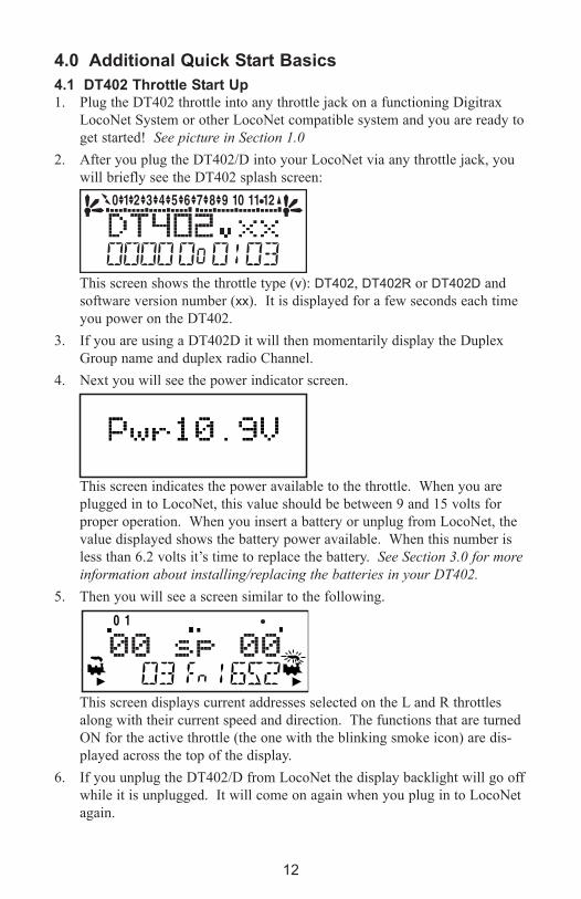
4.1 DT402 Throttle Start Up 1. Plug the DT402 throttle into any throttle jack on a functioning Digitrax
LocoNet System or other LocoNet compatible system and you are ready to
get started! See picture in Section 1.0
2. After you plug the DT402/D into your LocoNet via any throttle jack, you
will briefly see the DT402 splash screen:
This screen shows the throttle type (v): DT402, DT402R or DT402D and
software version number (xx). It is displayed for a few seconds each time
you power on the DT402.
3. If you are using a DT402D it will then momentarily display the Duplex
Group name and duplex radio Channel.
4. Next you will see the power indicator screen.
This screen indicates the power available to the throttle. When you are
plugged in to LocoNet, this value should be between 9 and 15 volts for
proper operation. When you insert a battery or unplug from LocoNet, the
value displayed shows the battery power available. When this number is
less than 6.2 volts it’s time to replace the battery. See Section 3.0 for more
information about installing/replacing the batteries in your DT402.
5. Then you will see a screen similar to the following.
This screen displays current addresses selected on the L and R throttles
along with their current speed and direction. The functions that are turned
ON for the active throttle (the one with the blinking smoke icon) are dis-
played across the top of the display.
6. If you unplug the DT402/D from LocoNet the display backlight will go off
while it is unplugged. It will come on again when you plug in to LocoNet
again.

13
4.2 DT402 Series Throttle keyboard Layout
FUNC KeyPress once to changeto Fn (function) mode
LOCO KeyPress to enteraddressselection mode.Press again to select address.
LCD Display
press to reversedirection of theL throttle knob
MU KeyPress to enterconsist mode
L Throttle Knob
R Throttle Knob
Y + KeyYes/Increase Key
N - KeyNo/Decrease Key
EMERGENCYSTOP Key
Press to reversedirection of the R throttle knob
L Reverse Key
R Reverse Key
SWCH KeyPress to enterswitch mode.
DISP KeyDisplay/Dispatch
PROG KeyEnter programmingmode & scroll thruprogramming modesavailable
EDIT KeyUse to edit clock,routes, etc. & to status edit decoders
FIND KeyUsed to locate transponderson the layout
BACK KeyBacks up a step
EXIT KeyReturns you toFn mode for normal loco opertions.
ENTER KeyCompletes currentaction and returns toFn mode.
OPTN t KeyLets you set
DT400 options&
Sets switches to t (thrown)
CLOC c KeyDisplays fast
clock time&
Sets switches to c (closed)
PWR KeyTurns track
powerOn or Off
&FLASHLIGHT
Numeric Key Pad0-12. Keys for bell, horn, copuler, light. Direct accessto addresses, functions& switches.
Remember, the EXIT Key will take you back to the Fn Mode for Normal Loco Operations.
FlashlightLED
InfraredLEDs

14
4.3 DT402 Series Throttle Controls At A Glance
1. The DT402 handheld has two knobs called the L Throttle (Left) and the
R Throttle (Right). The throttles are used for speed control, direction
changes, and input of information for operation of your railroad.
2. The row of numbers (0-12) across the top of the display are the functions
being used by the active locomotive throttle.
3 The larger numbers in the middle of the screen indicate the speed of the
locomotives being controlled by the throttles.
4. The numbers at the bottom of the display are the locomotive addresses,
and correspond to the digital decoder that is in each locomotive.
5. There are two locomotives located in the lower corners of the display, one
for the L Throttle and one for the R Throttle. Blinking smoke above the
locomotive indicates which throttle is currently active.
6. There are Direction Indicators (arrow heads) located under each locomotive
which indicate the direction of travel for each locomotive. The arrows
indicate whether the locomotive is moving forward or reverse, not the
direction of travel on the track.
7. The function numbers and text information displayed on the display screen
is for the active throttle. Keypad entries control functions for the active
throttle.
8. The current mode of operation is shown in center of the bottom line of the
display. The normal operating mode is Fn or Function Mode for running
trains. In this mode, the throttle knobs and direction keys control the speed
and direction of the locos. The Y / + and N / - keys can also be used to
increase or decrease speed. The numeric keypad is used for direct access
to functions.
L Throttle
Speed
Address
Direction
R Throttle
Speed
Address
Direction
L R
Blinking Smoke Icon indicates
that the R Throttle is active.
Functions displayed
correspond to the active throttle

15
4.4 Track power on and offThe TRACK POWER indicator on your DT402/D and TRACK STATUS indica-
tor on your DCS100 command station show whether track power is on or off.
The first time you plug in your throttle, track power will usually be off. Before
you can run trains, you will need to turn on the track power. Look at your
DCS100 or DT402/D to determine whether the track power is on or off.
When track power is off:
• DCS100 TRACK STATUS indicator is off,
• DCS100 OFF LINE indicator is on, and
• DT402 TRACK POWER Indicator is off (TRACK POWER indicator is
a small dot in the top line on the right side of the display).
When track power is on
• DCS100 TRACK STATUS indicator is lit,
• DCS100 OFF LINE indicator is off, and
• DT402’s TRACK POWER Indicator is on (small dot in the top line on
the right side of the display).
Turn track power on and off1. Press the PWR key on the DT402. You will see a screen similar to the one
below. You will now be able to toggle the track power on/off:
2. Press the N / - key to toggle the track power off. The TRACK POWER
Indicator on your DT402 and on your Command Station will go off.
3. Press the Y / + key to toggle the track power on. The TRACK POWER
Indicator on your DT402 display and the TRACK STATUS LED on your
Command Station will come on solid.
4. Press the PWR key again to return the DT402 to the operating mode.
5. If the TRACK POWER Indicator is blinking and the display shows Trk=Idle
then the layout is frozen in the “IDLE” state and no locomotives will move.
To exit this state simply turn on track power again.
NOTE: To be sure that the signal is available everywhere on the layout, use a
screwdriver blade or a coin across the rails to cause a short circuit. You
will hear the 4 beeps and the DCS100 will shut down. Remove the short
and the DCS100 will beep once and resume normal operation.
Since the control signal travels with the power on the rails, it is impor-
tant to have power to the track in all locations so that the decoders can
see the signal and respond to your commands.
This display shows a DT402 in PWR mode.
Track Power Indicator Track Power Indicator
16
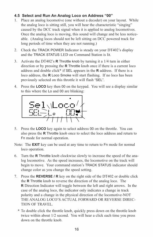
4.5 Select and Run An Analog Loco on Address “00”1. Place an analog locomotive (one without a decoder) on your layout. While
the analog loco is sitting still, you will hear the characteristic “singing”
caused by the DCC track signal when it is applied to analog locomotives.
Once the analog loco is moving, this sound will change and be less notice-
able. (Analog locos should not be left sitting on DCC powered track for
long periods of time when they are not running.)
2. Check the TRACK POWER Indicator is steady on your DT402’s display
and the TRACK STATUS LED on Command Station is lit.
3. Activate the DT402’s R Throttle knob by turning it a 1/4 turn in either
direction or by pressing the R Throttle knob once if there is a current loco
address and double click* if SEL appears in the R address. If there is a
loco address, the R Loco Smoke will start flashing. If no loco has been
previously selected on this throttle it will flash “SEL”.
4. Press the LOCO key then 00 on the keypad. You will see a display similar
to this where the Lo and 00 are blinking:
5. Press the LOCO key again to select address 00 on the throttle. You can
also press the R Throttle knob once to select the loco address and return to
Fn mode for normal operation.
Note: The eXIT key can be used at any time to return to Fn mode for normal
loco operation.
6. Turn the R Throttle knob clockwise slowly to increase the speed of the ana-
log locomotive. As the speed increases, the locomotive on the track will
begin to move. Your command station’s TRACK STATUS indicator should
change color as you change the speed setting.
7. Press the ReVeRSe / R key on the right side of the DT402 or double click
the R Throttle knob to reverse the direction of the analog loco. The
R Direction Indicator will toggle between the left and right arrows. In the
case of the analog loco, the indicator only indicates a change in track
polarity and a change in the physical direction of the locomotive-NOT
THE ANALOG LOCO’S ACTUAL FORWARD OR REVERSE DIREC-
TION OF TRAVEL.
* To double click the throttle knob, quickly press down on the throttle knob
twice within about 1/2 second. You will hear a click each time you press
down on the throttle knob.
17
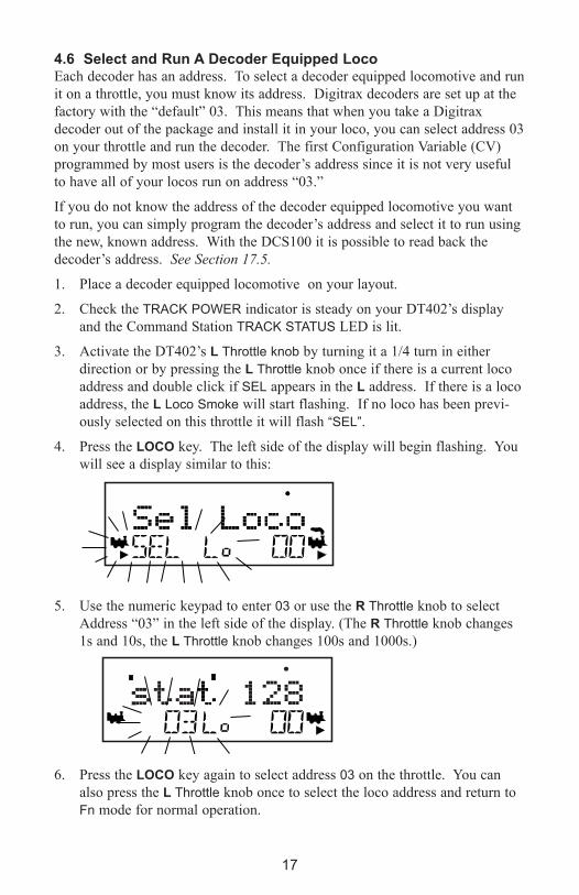
4.6 Select and Run A Decoder equipped Loco Each decoder has an address. To select a decoder equipped locomotive and run
it on a throttle, you must know its address. Digitrax decoders are set up at the
factory with the “default” 03. This means that when you take a Digitrax
decoder out of the package and install it in your loco, you can select address 03
on your throttle and run the decoder. The first Configuration Variable (CV)
programmed by most users is the decoder’s address since it is not very useful
to have all of your locos run on address “03.”
If you do not know the address of the decoder equipped locomotive you want
to run, you can simply program the decoder’s address and select it to run using
the new, known address. With the DCS100 it is possible to read back the
decoder’s address. See Section 17.5.
1. Place a decoder equipped locomotive on your layout.
2. Check the TRACK POWER indicator is steady on your DT402’s display
and the Command Station TRACK STATUS LED is lit.
3. Activate the DT402’s L Throttle knob by turning it a 1/4 turn in either
direction or by pressing the L Throttle knob once if there is a current loco
address and double click if SEL appears in the L address. If there is a loco
address, the L Loco Smoke will start flashing. If no loco has been previ-
ously selected on this throttle it will flash “SEL”.
4. Press the LOCO key. The left side of the display will begin flashing. You
will see a display similar to this:
5. Use the numeric keypad to enter 03 or use the R Throttle knob to select
Address “03” in the left side of the display. (The R Throttle knob changes
1s and 10s, the L Throttle knob changes 100s and 1000s.)
6. Press the LOCO key again to select address 03 on the throttle. You can
also press the L Throttle knob once to select the loco address and return to
Fn mode for normal operation.

18
The illustration below shows the display after address “00” is selected on the
R Throttle and address “03” is selected on the L Throttle, We see the TRACK
POWER Indicator On in the top line, the speed bar graphs at 0 speed and the
text area also at 0 speed for both throttles.
7. Turn the L Throttle knob clockwise slowly to increase the speed of the
decoder equipped locomotive. As the value in the left display increases,
the decoder equipped locomotive on the track will begin to move.
8. Press the L / ReVeRSe key on the left side of the DT402 or double click
the L Throttle knob to reverse the direction of the loco. The L Direction
Indicator under the loco icon will toggle between the left and right arrows.
In the case of the decoder equipped loco, the arrow indicates locomotive
direction (forward or reverse), not the direction of travel on the track.
9. Use the R Throttle knob and ReVeRSe / R key to control the analog loco
and the L Throttle knob and L / ReVeRSe key to control the decoder
equipped loco. You can control both at the same time.
Notice as you use each throttle knob or direction key that the loco with the
“blinking smoke” will change to that side of the throttle. The side with the
“blinking smoke” indicator is the active throttle. To control the headlight or
other functions, the locomotive must be on the active throttle.
2 digit address 03Selected on theL ThrottleRunning at 20% speedIn reverseFunction 0, 1, & 3 on.
An analog loco address 00Selected on theR ThrottleRunning at 25% speedThe direction arrow belowthe Loco Icon does not indicate actual directionfor Analog locos.
Track Power Indicator ON
Throttle in normal operationsmode indicated by Fn.In Function (Fn) ModeThrottle knobs control Loco'sSpeed & DirectionKeypad entries control functions

19
4.7 Shutting Down the SystemWhen you are finished with your session, shut down the Super Chief Xtra by
turning off power to the system.
Some users prefer to “dispatch” or release all addresses active in their system
before shutting down. This can prevent unexpected results when you power up
the layout again. The dispatch procedure is covered in detail in Section 11.5.
1. Press the PWR key followed by the N / - key, the TRACK POWER
Indicator on the DT402 and the TRACK STATUS Indicator on your
DCS100 command
station will go off.
2. Move the command station’s MODE switch to the SLEEP position .
3. Turn off the power supply to the system.
The power to the command station can be left on all the time if desired. In
“sleep” mode, the command station consumes very little energy. In this state
the command station provides keep alive power to all throttles that are connect-
ed to LocoNet.
4.8 Resuming your sessionWhen you are ready to resume your session:
1. Turn on the power to the system.
2. Be sure the DCS100’s MODE switch is in the “RUN” position. All
attached throttles will beep within a couple of seconds to indicate that
LocoNet is active again.
3. Check the TRACK STATUS indicator on the DCS100. If it is not lit then
turn track power on as follows: Press the PWR key followed by the Y / +
key, the TRACK POWER Indicator on the DT402 and the TRACK STATUS
Indicator on your command station will come on.
4.9 Quick Start Problems?If you encountered problems at any step in this Quick Start Section:
First, try backing up a step until you get results described. The steps included
in this installation procedure are set up so that if you follow them carefully, any
problems you encounter will be easy to isolate and correct.
If that does not work or if you have other questions or problems, we encourage
you to call, fax or e-mail Digitrax or your favorite dealer. The Digitrax Tech
Support Depot is always available at www.digitrax.com/help
There are thousands of successful Digitrax installations around the world and
we want to be sure that yours is one of them.

20
QUICK INSTALLATION Notes for users of Digitrax decoders that have
already been programmed and decoders not made by Digitrax:
1. The DCS100 command station defaults to 128 speed step operation so, if
you are using a locomotive with a decoder that does not have 128 step
capability you will have to adjust either the decoder or the DCS100 com-
mand station so that both are using the same number of speed steps to
communicate. You can status edit each individual decoder (see Section 19)
or you can change the DCS100’s system default and run all of your
decoders with fewer speed steps to accommodate these decoders (see
Section 9.0).
2. If you can’t control the operation of the lights in your decoder equipped
locomotive with the DT402 (in default 128, or 28 speed step mode), be
sure that the decoder itself is programmed in advanced 28 speed step
mode. Please refer to Section 19.1 for corrective measures.
4.10 What’s Next? Now that you have successfully set up your Super Chief Xtra Set, it’s time to
learn more about the features and options offered by Digitrax Complete Train
Control and the LocoNet system. Read the manual and take time to understand
and master each topic. Your Super Chief Xtra Set is the gateway to all the pos-
sibilities and options offered by Digitrax so the best advice is to take it step by
step and don’t try to do everything at once. For additional resources check out
the Digitrax web site at www.digitrax.com.

21
5.0 LocoNet: The Digitrax Difference!
5.1 System Architecture System architecture is the biggest difference among layout con-
trol systems. System architecture is the way the components of
a control system communicate among themselves. Digitrax
LocoNet is a Peer to Peer local area network (LAN) designed
specifically for model railroad operation. LocoNet wiring is
cost effective, flexible and expandable to accommodate almost anything you
want to do with your railroad today and in the future.
The system architecture used for communication within DCC and other control
systems is not standardized. Therefore DCC compatibility encompasses only
decoders, command stations and boosters but not throttles and other devices.
In addition, devices that require feedback and other types of signals that are
outside the domain of DCC, such as detection systems and transponding, are
not standardized. LocoNet is a hybrid system that incorporates DCC and other
technologies to expand the capabilities of your system. Your Digitrax system
gives you the best of both worlds with a system that is compatible with today’s
DCC standards and also goes beyond those standards to deliver enhanced sys-
tem performance and advanced features that are far beyond the scope of DCC.
With Digitrax, it’s Complete Train Control!
5.2 event Driven or Polled?LocoNet is an event driven network. The command station on LocoNet waits
for input from other components before sending commands to the layout. For
example, if there are 10 throttles on LocoNet and throttle #1 sends a command,
the command station sees it and executes immediately. With a distributed net-
work like LocoNet, new features can be added by simply plugging in new
hardware or software. Since LocoNet is a peer to peer network, devices on
LocoNet can act independently of the command station, too. Feedback is
incorporated in LocoNet’s communication scheme so you don’t need to wire a
separate feedback bus.
Other systems typically use polled buses or “networks.” In this case, the com-
mand station must “ask” each of the throttles or other devices in turn: “Do you
have input for me?” The device must wait for the command station to poll all
the devices on the bus before it sends the command. This arrangement can
slow down response times and limit the number of devices that can be handled
by the system as more and more devices are added. With centralized process-
ing in a master/slave control type system like this, adding new features usually
means updating the command station software when new components are
added since devices can’t operate on the system unless the master command
station knows how to handle them. To add feedback capabilities to this type of
system, a separate feedback bus may also be necessary.

22
5.3 Network SpeedIs faster network speed better? Not necessarily, it depends on whether the system
uses event driven or polled architecture. The NMRA’s track control packet for-
mat sets the “speed limit” for all DCC systems. Going faster than the “speed
limit” won’t make a system work any better and causes problems on the network.
LocoNet is engineered for the lowest speed that will get the job done. Because
LocoNet is event driven, slower network speeds are possible. With slower net-
work speed, signal distortion on the network is not a problem. Because
LocoNet uses a slower network speed, it’s free-form wiring scheme is simple
and flexible. With LocoNet you can “branch” or “tee” anywhere in your net-
work wiring and no termination is needed.
Polled systems generally have to go a lot faster than the “speed limit” to
accommodate the large amount of traffic generated by polling and to prevent
delays between the time a command is issued by the throttle and the time the
system executes the command. The big problem is that as the network speed
increases, so does signal distortion. Polled systems generally use linear termi-
nated bus wiring to solve this problem. Free-form wiring like LocoNet is not
usually possible with polled systems.
5.4 LocoNet Personal edition LocoNet Personal Edition is available to all model railroaders through our web
site. This edition of LocoNet is available so that you can develop your own
personal LocoNet applications.
5.5 LocoNet expansion The following figure shows some of the expansion possibilities available with
LocoNet. This figure is an extension of the Super Empire Builder Xtra in
Section 1.0. With LocoNet you can add:
• More boosters to give you more power to let you run more trains,
• More throttles for more operators,
• Different types of throttles,
• More throttle jacks for convenient walkaround operation,
• Infrared or radio capability for more freedom for operators,
• Accessory decoders for turnout and accessory control,
• Detection,
• Transponding,
• Signaling,
• A personal computer to automate operations or for dispatching,
• Automatic reversing with a booster or power manager,
• The list goes on and on.
With LocoNet, you customize your layout to run the way you want it to run!
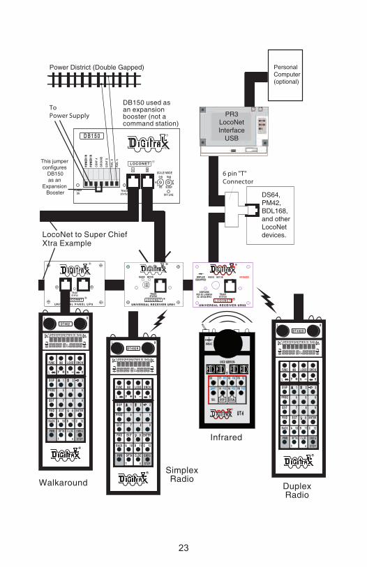
23
D B 1 5 0 D B 1 5 0
T R A C KT R A C KS T A T U SS T A T U S
P O W E RP O W E RO NO N O F F L I N EO F F L I N E
O / GO / G
NN
H OH O
M O D EM O D E
PPR U NR U N
L O C O N E TL O C O N E T
AA BBS C A L ES C A L E
S L E E PS L E E PRR
ToPower Supply
R
R
PersonalComputer(optional)
DS64,PM42, BDL168,and otherLocoNet devices.
Power District (Double Gapped)
6 pin "T"Connector
CO
NF
BC
ON
F B
RA I
L B
RA I
L B
POW
ER I
NPO
WER
IN
CO
NF
AC
ON
F A
RA I
L A
RA I
L A
POW
ER I
NPO
WER
IN
GR
OU
ND
GR
OU
ND
L O C O N E TL O C O N E T
UNIVERSAL RECEIVER UR91UNIVERSAL RECEIVER UR91
RR
T R A C KT R A C KS T A T U SS T A T U S
N E T / I RN E T / I RR A D I OR A D I O
RR
L O C O N E TL O C O N E T
U N I V E R S A L P A N E L U P 5U N I V E R S A L P A N E L U P 5
RR
RR
T R A C KT R A C KS T A T U SS T A T U S
This jumper configures
DB150as an
Expansion Booster
LocoNet to Super Chief Xtra Example
DB150 used asan expansion booster (not acommand station)
WalkaroundSimplexRadio
Infrared
DuplexRadio
U N I V E R S A L R E C E I V E R U R 9 2U N I V E R S A L R E C E I V E R U R 9 2
EQUIPPEDEQUIPPEDDUPLEXDUPLEX
C O N T A I N SC O N T A I N SF C C I D : L V 3 R F 2 4F C C I D : L V 3 R F 2 4I C : 3 0 1 5 A - R F 2 4I C : 3 0 1 5 A - R F 2 4
RR
F U N CF U N C M UM U S W C HS W C H
RR
cc
L O C OL O C O
Y Y + +LL
tt
CCBBAAB A C KB A C K
O P T NO P T N C L O CC L O CP W RP W R
1 01 0 1 11 1 1 21 2
11 22 33
44 55 66
E N T E RE N T E R00E X I TE X I T
77 88 99
D I S PD I S P
P R O GP R O G
E D I TE D I T
F I N DF I N D
__
RRLLD T 4 0 2 DD T 4 0 2 D
N
E M R G
S T O PRR
F U N CF U N C M UM U S W C HS W C H
RR
cc
L O C OL O C O
Y Y + +LL
tt
CCBBAAB A C KB A C K
O P T NO P T N C L O CC L O CP W RP W R
1 01 0 1 11 1 1 21 2
11 22 33
44 55 66
E N T E RE N T E R00E X I TE X I T
77 88 99
D I S PD I S P
P R O GP R O G
E D I TE D I T
F I N DF I N D
__
RRLLD T 4 0 2D T 4 0 2
N
E M R G
S T O P
RR
F U N CF U N C M UM U S W C HS W C H
RR
cc
L O C OL O C O
Y Y + +LL
tt
CCBBAAB A C KB A C K
O P T NO P T N C L O CC L O CP W RP W R
1 01 0 1 11 1 1 21 2
11 22 33
44 55 66
E N T E RE N T E R00E X I TE X I T
77 88 99
D I S PD I S P
P R O GP R O G
E D I TE D I T
F I N DF I N D
__
RRLLD T 4 0 2 RD T 4 0 2 R
N
E M R G
S T O P
PR3LocoNetInterface
USB
00 00 00 00
24
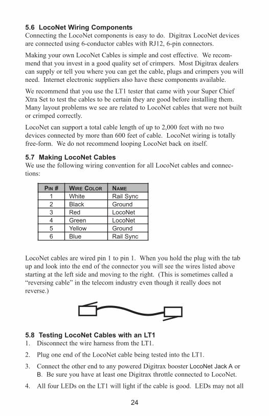
5.6 LocoNet Wiring ComponentsConnecting the LocoNet components is easy to do. Digitrax LocoNet devices
are connected using 6-conductor cables with RJ12, 6-pin connectors.
Making your own LocoNet Cables is simple and cost effective. We recom-
mend that you invest in a good quality set of crimpers. Most Digitrax dealers
can supply or tell you where you can get the cable, plugs and crimpers you will
need. Internet electronic suppliers also have these components available.
We recommend that you use the LT1 tester that came with your Super Chief
Xtra Set to test the cables to be certain they are good before installing them.
Many layout problems we see are related to LocoNet cables that were not built
or crimped correctly.
LocoNet can support a total cable length of up to 2,000 feet with no two
devices connected by more than 600 feet of cable. LocoNet wiring is totally
free-form. We do not recommend looping LocoNet back on itself.
5.7 Making LocoNet CablesWe use the following wiring convention for all LocoNet cables and connec-
tions:
LocoNet cables are wired pin 1 to pin 1. When you hold the plug with the tab
up and look into the end of the connector you will see the wires listed above
starting at the left side and moving to the right. (This is sometimes called a
“reversing cable” in the telecom industry even though it really does not
reverse.)
5.8 Testing LocoNet Cables with an LT11. Disconnect the wire harness from the LT1.
2. Plug one end of the LocoNet cable being tested into the LT1.
3. Connect the other end to any powered Digitrax booster LocoNet Jack A or
B. Be sure you have at least one Digitrax throttle connected to LocoNet.
4. All four LEDs on the LT1 will light if the cable is good. LEDs may not all
PIN # WIRe COLOR NAMe
1 White Rail Sync
2 Black Ground
3 Red LocoNet
4 Green LocoNet
5 Yellow Ground
6 Blue Rail Sync

25
be the same brightness, this is normal.
NOTE: Only three LEDs will light if no LocoNet throttle is plugged in to
the system.
5. If any of the LEDs fail to light, recrimp the plugs on the LocoNet cable
and retest.
5.9 LocoNet Throttle jacks and LocoNet Connection jacksDigitrax LocoNet devices are connected using 6-conductor LocoNet cables.
All LocoNet devices have LocoNet Connection Jacks that allow you to daisy
chain the network around the layout.
Some Digitrax devices like the Universal Panels also have LocoNet Throttle
Jacks. The Throttle Jacks should not be used for connecting LocoNet devices
that will be daisy chained beyond themselves or that use rail sync. You can use
these jacks for throttles, DS64s and PM42s. Consult the installation instruc-
tions for the particular device you are installing to determine whether it can use
the Throttle jacks or if a Connection jack is necessary.
All Digitrax throttles are memory walkaround throttles, some are equipped
with infrared LEDs and others are radio throttles. Even if you use wireless
throttles, you will still need to install at least one or two LocoNet throttle jacks
on your layout. Any RJ12 6 conductor phone jack can serve as a LocoNet
throttle jack. The problem with using RJ12 telephone style jacks is that you
will have to wire them and secure them to the layout so that they don’t come
loose.
5.10 Installing the Universal Panel (UP5)The Digitrax Universal Panel UP5 or UR92, included with your Super Chief
Xtra Starter Set, provides a simple plug and play alternative to wiring RJ12
telephone style jacks around the layout. This fascia mounted panel provides 2
RJ12 LocoNet throttle jacks as well as a “TRACK STATUS” indicator on the
front panel. The back of the panel provides 2 RJ12 LocoNet connection jacks
for daisy chaining to the next LocoNet device on the network. An additional
RJ12 throttle jack is provided on the side of the UP5 for connecting additional
throttles or LocoNet devices. The panels provide a professionally finished look
to your layout fascia. UP5, UR90 (infrared receiver), UR91 (simplex radio
receiver) and UR92 (duplex radio transceiver) all provide additional LocoNet
Throttle Jacks and Connection Jacks for your system.
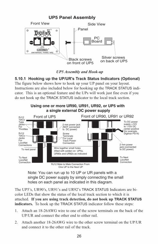
26
UP5 Assembly and Hook-up
5.10.1 Hooking up the UP/UR's Track Status Indicators (Optional)The figure below shows how to hook up your UP panel on your layout.
Instructions are also included below for hooking up the TRACK STATUS indi-
cator. This is an optional feature and the UPs will work just fine even if you
do not hook up the TRACK STATUS indicator to the local track section.
The UP5’s, UR90’s, UR91’s and UR92’s TRACK STATUS Indicators are bi-
color LEDs that show the status of the local track section to which it is
attached. If you are using track detection, do not hook up TRACk STATUS
indicators. To hook up the TRACK STATUS indicator follow these steps:
1. Attach an 18-26AWG wire to one of the screw terminals on the back of the
UP/UR and connect the other end to either rail.
2. Attach another 18-26AWG wire to the other screw terminal on the UP/UR
and connect it to the other rail of the track.
L O C O N E TL O C O N E T
U N I V E R S A L P A N E L U P 5U N I V E R S A L P A N E L U P 5
RR
RR
T R A C KT R A C K
S T A T U SS T A T U S
Black screws
on front of UP5
Silver screws
on back of UP5
UP5 Panel Assembly
Side View
PCBoard
Front View
Panel
Front of UR90, UR91 or UR92
2 mm powerjack (connectedto DC power)
To DC powersupply +12Vto +15V DCcenter positive(for example,Digitrax PS14)
Front of UP5 RJ12TelCo TypeJacksFor Throttles
ScrewTerminalsFor LocalTrack PowerConnection
2 mm power jack(NOT connectedto DC power)
To NextLocoNetConnection
To NextLocoNetConnection
Wire together small holes
(filled with solder) on UP5s,
UR90s and UR92s as indicated
To next panel
Note: You can run up to 10 UP or UR panels with a
single DC power supply by simply connecting the small
holes on each panel as indicated in this diagram.
Using one or more UR90, UR91, UR92, or UP5 with
a single external DC power supply
RJ12 Male to Male Connection From
One UP to the Next UP
RJ12
TelCo
Jacks
For
LocoNet
Connections

27
3. If you are hooking up more than one UP/UR, be consistent in hooking up
all track sections alike with respect to which terminal is connected to
which rail. This is not required but strongly recommended.
As you operate your layout, the UP/UR TRACK STATUS Indicator will be lit
when the track is powered. The LED glows red or green when you are operat-
ing an analog locomotive and the system is "zero stretching." When you are
using DCC only, the LED will glow orange. This color change is a useful
diagnostic tool.
Now that you have learned more about LocoNet and how to connect the
devices using LocoNet cables, let look at installing Digitrax on your layout!
6.0 Advanced Installation of Digitrax On Your LayoutEarly proponents of DCC touted the fact that you can hook up your railroad
with just two wires. While this is technically correct, there are some things
you will need to consider to get the most out of Digitrax Complete Train
Control.
Because the signal and the power that runs the trains are one in the same, you
must provide adequate power to all areas of your layout for reliable Digitrax
operation. If the decoder in the locomotive does not see track power, it will
not see the signal and it won’t run. Digitrax boosters need enough track
power to sense short circuits to operate properly. Your layout must have a
power bus and feeder system that can safely support the continuous full current
rating of any booster anywhere on the layout.
The good news is that if your current layout runs with regular DC then it will
probably run on Digitrax. Unless you need to set up power districts on your
layout for added power, the only gaps you need are for hard shorts like reverse
loops and uninsulated frogs. If you are already wired for block control, you
probably don’t need to rewire. Just open all your blocks so that the entire track
has power and you are ready to go. If you are using common rail wiring, we
recommend that you divide the layout into power districts by double gapping
between power districts.
6.1 Setting Up A Programming TrackDecoders are programmed when the command station sends programming
information to them through the rails. There are two ways of programming
decoders.
6.1.1 Ops mode programmingOps mode programming (see Section 17.3) is done on the layout with program-
ming directed to a specific decoder address. Operations mode programming is
used to make changes other than address to locos while they are running on the
layout.

28
6.1.2 Service mode programming (Using a programming track)Service mode programming broadcasts a message to all decoder equipped locos
that are on the track. Because this is a broadcast method and will affect all
locos, you will need to set up a programming track so that the programming
instructions only go to the loco you want to program. Decoder addresses can
only be programmed using service mode programming. Service mode is also
used to program all other Configuration Variables (CVs) as well.
Your DCS100 sends these programming commands using the PROG A and
PROG B outputs. See the following figure for hook up information. PROG A
and PROG B are actually a second set of outputs that allow you to program
decoders while still running the layout on the RAIL A and RAIL B outputs. You
will need to set up a programming track for service mode programming that
will allow you to program a loco without shutting down the rest of the layout
during programming. Follow the steps outlined in Section 11.3 to program
your decoder equipped locomotives.
Programming Track With DCS100
6.2 Direct Home Wiring vs. Common Rail WiringDigitrax strongly recommends direct home wiring where each power district
and its booster are electrically isolated. This type of wiring is safer and more
convenient to work with for debugging and for adding reversing sections and
detection later. If you are planning to use whole layout common rail wiring,
please have your dealer special order opto-isolated boosters for your layout.
D C S 1 0 0 D C S 1 0 0
T R A C KT R A C K
S T A T U SS T A T U S
P O W E RP O W E RO NO N O F F L I N EO F F L I N E
O / GO / G
NN
H OH O
M O D EM O D E
PP
R U NR U N
L O C O N E TL O C O N E T
AA BBS C A L ES C A L E
S L E E PS L E E PRR
R
R
PRO
G B
PRO
G B
RAI L
BRA
I L B
POW
ER IN
POW
ER IN
PRO
G A
PRO
G A
RAI L
ARA
I L A
POW
ER IN
POW
ER IN
GRO
UND
GRO
UND
DCS100 Command Station
NOTE: Some wiring omitted for clarity
PROG BPROG A
RAIL ARAIL B
Programming Track(Powered by DCS100 PROG A & B)
DoubleGaps
Main Layout
C O N F I GC O N F I G N E TN E T

29
Note for detection and signaling wiring common rail can be used within power
districts that are wired for direct home and use regular Digitrax boosters.
Remember, no matter how you control your trains, you should always use
safe wiring practices.
6.3 Recommended wire sizes for power bus and track feedersOn an average size layout Digitrax recommends that the power bus from the
booster be at least 16AWG. When feeding areas up to 50’ from the booster, we
recommend using 12 AWG wire for the power bus.
From the main power bus, we recommend dropping feeders (22-24AWG)
approximately every 6 to 10 feet of track. Sets of feeders should be wired to
both rails and we recommend at least 2 sets of feeders per power district.
The wire gauges used (AWG) can be increased or decreased, depending on
your actual layout dimensions and operating power/current loads.
6.4 Other Track Wiring Considerations1. Power connections to a large layout should be via a parallel conductor
power bus similar to that used in most conventional layouts, with feeder
wires to the track about every 6-10 feet.
2. When using more than one booster, be sure that the RAIL A and RAIL B
connections for all boosters are made in the same track orientation, i.e.
RAIL A to left rail and RAIL B to right rail or vice versa.
3. Do not short either the RAIL A or RAIL B output of the DCS100 to
GROUND.
4. To minimize the possibility of radio interference, twist all conductors.
5. Circulating ground loops may cause problems with your layout. We often
see this on existing layouts that have been added on to over the years. If
you are experiencing problems in a localized area of your layout, you may
need to look for this problem and fix it.
6. Wire the power feeds away from the boosters and command stations, in a
radial “star like” configuration to minimize the possibility of creating
“magnetic induction” loops.
7. Do not place ANY filters or capacitors across the track. These will
short out the control signals. Be sure that no capacitors are bridging your
power districts.
6.5 Layout Power DistrictsA power district is an electrically isolated section of the layout including the
power wiring, booster and power supply that drives it. Power districts are used
for power distribution, not for train control as with DC blocks. Power districts
may be divided into sub-districts for short circuit management within the
power district or for auto reversing. Even though blocking is not required for

30
train operation with DC, dividing the layout up into power districts (and sub-
districts) is needed for the following reasons:
6.5.1 Number of LocosAdditional power districts may be needed to provide enough power to operate
more locomotives than one power supply alone can handle. For example a 5
amp booster and power supply will operate between 10 and 15 average N-scale
locomotives and between 6 and 10 HO locomotives. If you wish to run more
locos on your layout, then you will need to set up more power districts to pro-
vide more total power.
6.5.2 Short CircuitsAdditional power districts and sub-districts can be used to prevent the whole
layout from shutting down when short circuits (like de-rails or an operator run-
ning a switch) occur in any given power district or sub-district. If a short
occurs in one district or sub-district, only that area of the layout shuts down,
the rest of the layout keeps operating.
6.5.3 To set up power districts and sub-districts on your layout:1. Determine how you want to arrange power districts and sub-districts.
2. Double gap the rails at each end of the power district and single gap for
sub-districts within districts.
3. Connect a DCS100 or other Digitrax booster and power supply to each dis-
trict. Use a PM42 with your DCS100s to set up sub-districts.
4. Connect the DCS100 or other Digitrax boosters to the command station via
LocoNet.
6.5.4 How can I be sure I have enough power to run my trains?Use the “quarter trick.” Once your Digitrax booster is installed and the layout
is powered up, use a quarter (or other piece of conductive material) to short
both rails at various places on the layout. If you have enough power at that
location, the booster will chirp and shut down. If the booster does not shut
down, then you need to add more feeders.
6.6 Adding a DB150 BoosterYour DCS100 is a command station and booster in one unit. The DCS100 is
not intended to be used as a booster only. When you are ready to expand your
Super Chief Xtra Set, we recommend that you add a DB150 Booster. Be sure
that you follow the directions on the following page when you add DB150s to
your system so that they are set up to run as boosters. See Section 6.8 for
information about setting up your DB150 as an auto-reversing booster.

31
1. Start with an un-powered DB150.
2. Connect the DB150‘s CONFIG A and GROUND terminals with a short
length of wire.
3. Set the DB150’s MODE switch to RUN.
4. Power up the DB150. The DB150 will automatically convert to booster
only operation when you power it up.
5. Connect the DB150 to your DCS100 on LocoNet via either LocoNet Jack
A or B using regular LocoNet Cables that have been tested with the LT1.
6. Use a coin to short one rail across the gap between the booster districts. If
there is no short, your installation is correct. If there is a short, swap the
Rail A & Rail B wire connections to the district.
7. You can add more DB150s by “daisy chaining” additional DB150 boosters
via the LocoNet Jack A or B on any DB150 in the system.
If you experience problems with operation after you add a DB150 to your sys-
tem, check to be sure that you have actually set it up as a booster by going
through the steps above again. We have seen this simple mistake cause operat-
ing problems with modular layouts when someone added a DB150 set up as a
command station to a layout that was already up and running with another
command station (DCS100 or DB150). In this case, two command stations can
be trying to run the same layout causing some undesirable operating results
such as trains that appear to be running away.
6.7 Reversing Section Wiring You can operate reversing sections manually or automatically with Digitrax
Complete Train Control using an auto-reversing booster, a reversing section
controller such as an AR1 or PM42. You must double gap (completely isolate)
both ends of the reversing section just like with any other layout. Note that
D B 1 5 0 D B 1 5 0
T R A C KT R A C KS T A T U SS T A T U S
P O W E RP O W E RO NO N O F F L I N EO F F L I N E
O / GO / G
NN
H OH O
M O D EM O D E
PPR U NR U N
L O C O N E TL O C O N E T
AA BBS C A L ES C A L E
S L E E PS L E E PRR
ToPower Supply
R
R
Power District (Double Gapped)
CO
NF
BC
ON
F B
RA I
L B
RA I
L B
POW
ER I
NPO
WER
IN
CO
NF
AC
ON
F A
RA I
L A
RA I
L A
POW
ER I
NPO
WER
IN
GR
OU
ND
GR
OU
ND
This jumper sets up the DB150
as an Expansion Booster
To anotherDB150 or DCS100

32
automatic reversing will not cause analog(non decoder equipped) locos to auto
reverse.
If you choose manual operation, use a DPDT switch or relay to handle the
polarity change as the loco enters and leaves the reversing section.
If you choose to use a DB150 auto reversing booster to completely automate
the reversing section, power the reverse loop with a DB150 and power supply
and the main layout with your DCS100 and power supply. The DCS100 when
running as your command station will not auto-reverse.
6.8 Using a DB150 as an AutoReversing Booster1. Start with an un-powered DCS100.
2. Connect the DB150’s CONFIG A and GROUND terminals and CONFIG B
and GROUND terminals with two short lengths of wire.
3. Set the DB150’s MODE switch to RUN.
4. Power up the DB150. The DB150 will automatically convert to automatic
reversing booster operation when you power it up.
5. Connect to your DCS100 or other DB150s on LocoNet via either LocoNet
Jack A or B using LocoNet Cables that were tested with an LT1.
Automatic Reversing Section Set-Up
D C S 1 0 0 D C S 1 0 0
T R A C KT R A C K
S T A T U SS T A T U S
P O W E RP O W E RO NO N O F F L I N EO F F L I N E
O / GO / G
NN
H OH O
M O D EM O D E
PP
R U NR U N
L O C O N E TL O C O N E T
AA BBS C A L ES C A L E
S L E E PS L E E PRR
R
R
PRO
G B
PRO
G B
RAI L
BRA
I L B
POW
ER IN
POW
ER IN
PRO
G A
PRO
G A
RAI L
ARA
I L A
POW
ER IN
POW
ER IN
GRO
UND
GRO
UND
D B 1 5 0 D B 1 5 0
T R A C KT R A C KS T A T U SS T A T U S
P O W E RP O W E RO NO N O F F L I N EO F F L I N E
O / GO / G
NNH OH O
M O D EM O D E
PPR U NR U N
L O C O N E TL O C O N E T
AA BBS C A L ES C A L E
S L E E PS L E E PRR
R
R
CONF
BCO
NF B
RAI L
BRA
I L B
POW
ER IN
POW
ER IN
CONF
ACO
NF A
RAI L
ARA
I L A
POW
ER IN
POW
ER IN
GROU
NDGR
OUND
DoubleGap
DoubleGap
DCC
DCC
Note: Some wiring omitted for clarity
DB150 BoosterSet Up forAutomatic Reversing
DCS100 Command Station/Booster(System Reference)
Jumper wires between CONFIG A and GROUND and CONFIG B and GROUND
LocoNet
33
Note that when the polarity change occurs, decoder equipped locomotives will
continue at the speed and in the direction commanded but any analog engines
running will respond to the polarity change by reversing direction.
To handle auto reversing, you will need two devices, one that acts as the sys-
tem polarity reference and another to detect a polarity mismatch and correct it.
If you are using two Digitrax boosters, one acts as the polarity reference and
the other handles the polarity reversal for the reversing section. You can also
use a DCS100 and PM42 to handle automatic reversing sections.
A single DB150 can be used to handle more than one reverse section however,
the unit can only fix a polarity mis-match at one gap at a time. If more than
one train is entering or leaving the reverse loops connected to a single booster
at the same time, a short will occur. More than one train can be in the reverse
loop at any time but, only one can cross the double gap at a time.
6.9 Using PM42 for Power Management and AutoReversingIf you want the benefits of setting up power districts on your layout but you
don’t need to add more power to run more trains, you can use a PM42 Quad
Power Manager to set up sub-districts within booster power districts. With
PM42 you can separate the output of one or more boosters into four sub-dis-
tricts that can be set up as either auto-reversing or as smart circuit breakers for
short circuit management.. For more information about this option, contact
your Digitrax dealer or check our web site at www.digitrax.com.
6.10 Using AR1 for AutoReversingIf you have a single reversing section that doesn’t need its own booster, you
can use the AR1 single unit auto reverser to make it auto-reversing.
6.11 Using DC and DCC together on the same layoutWhen running between DCC track sections and adjacent conventional DC
powered tracks, both rails must have insulating gaps.
The DC supply used must have some form of current control. A 5 to 10 Watt
12 Volt lamp placed in series with one of the DC power pack track leads will
work for this purpose. This allows the booster to drive the locomotive onto the
DC track with minimum interruption and stress to the booster, decoders and
locomotive wheels. When the lamp lights as the locomotive bridges the gaps it
acts as a “shock absorber” between the DCC and DC track sections. It is best
to cross these gaps quickly and not bridge the DCC and DC sections for any
longer than necessary.
Some new Digitrax users believe it is very important to be able to switch
between DC and DCC operation as they make the change from DC to DCC. In
practice we find that most of these customers make the change much sooner
that originally planned because of the operational benefits of Digitrax.
34
6.12 Troubleshooting Layout WiringInstalling Digitrax, or any other layout control system, on your layout will not
fix problems with layout wiring. Layout wiring can be very complex. We see
many examples of layouts that have “grown over the years” where wiring was
added and changed creating some very interesting electrical systems. If you
suspect that layout wiring might be a problem, we recommend that you discon-
nect the Digitrax equipment from the layout and test it on a small section of
track not connected to the layout to confirm that the problem is not with your
Digitrax equipment. If you find that there is a problem with your Digitrax
equipment, contact Digitrax tech support. If you find that your Digitrax equip-
ment is working fine, then it is time to de-bug the layout.
Observe the problem carefully and methodically.Does it occur with both DC and DCC operation?
If so, check track wiring.
Is it occurring everywhere on the layout or in one particular area?
With your Digitrax system hooked up, a coin or screwdriver to short out the
track. If no short occurs, you may not have enough feeders or your power sup-
ply may not be adequate. Use your LT1 to test the LocoNet cables attached to
the booster in the problem area.
Does it only occur with certain locomotives? Check the locomotives for mechanical problems and for damaged decoders. If
you programmed the decoders just before the problem started, re-program them
in case you entered values by mistake that are causing the problem.
Does it only occur with certain throttles, boosters or other equip-
ment?If the problem happens with just one piece of equipment, then you may need to
have it repaired. Check the RJ12 jacks to be sure the pins are not misaligned.
Does it occur only when plugged into a certain LocoNet jack? Check the wiring to that jack, particularly if you are using telco type jacks that
you wired yourself. Use your LT1 to test the LocoNet cable you are using in
that area of the layout.
Have you recently changed anything in your layout wiring? If so, try disabling
the change to see if they layout will run without the “upgrade.” You may need
to de-bug the upgraded wiring.
Have you changed any of the DCS100 or DT402 option settings? Try resetting
them to the default values and check to see if the layout will run.
Have you recently installed additional boosters on your layout? If so, check to be certain that these boosters are set up properly as boosters. If
more than one command station is operating on your layout, you may experi-
ence unexpected operation when the decoders are taking commands from two
different sources (command stations.)

35
When LocoNet is first powered up all Digitrax command stations check for
other command stations also operating on LocoNet. The first command station
that powers up will become the command station and all others will automati-
cally operate as boosters. If you have two separate operating LocoNets and
you connect them with a LocoNet cable, both command stations will continue
to operate and operating problems will occur. Modular layouts are at a high
risk of encountering this problem if more than one part of the layout is up and
running and then those parts are added together. Be sure in this case that you
completely power down all operating LocoNets before combining them into
one big LocoNet to avoid having more than one command station trying to run
the layout.
7.0 DCS100/200 Control Panel
7.0.1 DCS100 and DCS200The information in this manual applies to both the DCS100/DCS200 Command
Stations/Boosters unless specifically noted. We will refer to the DCS100 in all
instructions, but they apply equally to the DCS200. The DCS100 is a 5 amp
booster and the DCS200 is an 8 amp booster.
7.1 POWeR ON IndicatorThis green LED indicates that the power to the DCS100 is on.
7.2 POWeR IN TerminalsThe two POWER IN terminals on all Digitrax boosters and command stations
are the power input connections.
7.2.1 Power SupplyDigitrax recommends the PS515 power supply to power all DCS100s and the
PS2012 for DCS200s. There are many other power supplies and power packs
that can supply the input power for the DCS100. Check with your Digitrax
dealer for suggestions. Most regular DC model railroad power packs are not
able to supply 5 amps to the DCS100 booster, because they were designed to
run only 1 or 2 locomotives in a DC blocked system. With Complete Train
Control you’ll be running multiple locomotives in the same power district so,
you’ll need to provide more power to each district.
D C S 2 0 0
T R A C KS T A T U S
P O W E RO N O F F L I N E
O / G
N
H O
M O D E
O
R U N
L O C O N E T
A B S C A L E
S L E E PP
R
PRO
G B
RA I
L B
POW
ER I
N
PRO
G A
RA I
L A
POW
ER I
N
GR
OU
ND
C O N F I G N E T
D C S 1 0 0
T R A C KS T A T U S
P O W E RO N O F F L I N E
O / G
N
H O
M O D E
O
R U N
L O C O N E T
A B S C A L E
S L E E PP
R
PRO
G B
RA I
L B
POW
ER I
N
PRO
G A
RA I
L A
POW
ER I
N
GR
OU
ND
C O N F I G N E T

36
DCS100 Transformer Requirements
DCS200 Transformer Requirements
Power to the DCS100 should not be rapidly cycled ON-OFF-ON. When power
to the unit is switched off, wait 30 seconds before turning on the power again.
7.3 PROG A and PROG B TerminalsThe PROG A and PROG B terminals are the output for the second set of signals
which allow you to set up a programming track that can be used while the rest
of the layout continues to run.
PROG A and PROG B can also be used to set up braking sections on your lay-
out. This is useful if you want to stop trains at given points on the railroad, for
example at a station. Instructions for setting up brake sections can be found on
our web site, www.digitrax.com/ftp/brakedist.pdf
7.4 GROUND TerminalThe terminal marked ground provides electrical safety features and an RF
ground reference for minimum radiated noise. This should be the ONLY point
of any DCS100 installation that is connected to the AC safety ground pin pro-
vided on most 3 pin 110V AC power sockets. Grounding the system is a sensi-
ble safety precaution that should not be ignored.
7.5 RAIL B and RAIL A TerminalsConnect these terminals to the track on all Digitrax boosters and command sta-
tions. If you are using more than one booster, always connect the same rail to
the same terminal on each booster, for example connect all RAIL A terminals to
the right rail and all RAIL B terminals to the left rail or vice versa on all track
sections.
AC or DC AC 50/60 Hz DC
Max Input 20 RMS AC 28V DC
Min Input 12VAC 12V DC
Optimal Input Current 5 Amps 5 Amps
AC or DC AC 50/60 Hz DC
Max Input 20 RMS AC 28V DC
Min Input 12VAC 12V DC
Optimal Input Current 8 Amps 8 Amps

37
7.6 TRACk STATUS IndicatorThe TRACK STATUS indicator shows that there is voltage on RAIL A and RAIL
B terminals. The color indicates the type of signal.
• orange indicates the track is getting signals with no analog zero
stretching.
• green or red indicates a “stretched zero” signal is being used to
operate a conventional (analog) locomotive. When zero stretch-
ing is present, the decoder equipped locomotives will read their
digital commands normally and perform as commanded.
• not lit indicates there is no voltage on the track, the track power
to the DCS100 may be OFF.
7.7 LOCONeT jacks A and BThese jacks let you expand your Digitrax system by simply plugging LocoNet
devices in to the system. They can be used for throttles and other LocoNet
devices. These jacks are functionally the same and can be used interchange-
ably.
7.8 SCALe Switch (O/G, N, HO)This switch sets the maximum track voltage limit.
7.8.1 Track Voltage AdjustmentThe actual track voltage supplied by the DCS100 can be adjusted. To do this,
you must open the DCS100 case (this will not void your warranty).
1. Remove the DCS100 input power and disconnect all DCS100 leads.
Remove the gray plug from the front of the DCS100
2. Remove the two screws on the top and bottom of each side of the case.
3. Slide the gray front panel off the DCS100.
4. Be careful to avoid disturbing components other than the ones described in
the following steps.
5. Locate the small trimmer potentiometer behind the LocoNet Jack B and
Scale Switch.
6. Use a small screwdriver to turn the potentiometer clockwise to increase the
scale voltage setting. Turn it counter clockwise to decrease the voltage set-
ting.
7. To determine the actual track voltage, measure the DC voltage (unloaded)
Scale Max Track Voltage
O/G 20 volts
N 12 volts
HO 15 volts

38
from either the RAIL A or RAIL B terminal to the green ground wire on the
case. Multiply the measured voltage by 2 to determine the approximate
digital track voltage supplied.
7.9 MODe SwitchThe MODE switch settings are:
RUN normal operations.
OP customize the DCS100 by changing its option switch settings.
SLEEP shutdown the system and all throttles that are plugged in to the
system.
7.10 OFF LINe IndicatorThe DCS100 automatically shuts down when the heat sink temperature rises to
around 113-122 degrees Fahrenheit (45 to 50 degrees Celsius) and the OFF
LINE indicator will glow red. The DCS100 automatically resumes operation
when the heat sink cools down to approximately 104 degrees Fahrenheit (40
degrees Celsius).
The OFF LINE indicator will also be lit when there is no TRACK STATUS.
This is normal and you should not be alarmed.
7.10.1 Heat DissipationIt is normal for the DCS100 to be warm to the touch when it is in use. It is
designed to absorb and dissipate the power difference between the input volt-
age and the selected scale output stabilized voltage, at the current load being
drawn. If the unit is not able to dissipate excess heat, over temperature thermal
shutdown may occur. We recommend that you locate the boosters in a location
where they can dissipate heat. If you experience frequent over temperature
shutdowns, add a small fan to help cool the booster.
7.10.2 Troubleshooting DCS100 Shutdowns1. Move the DCS100 so that the heat sink has a flow of cool air.
2. Place the DCS100 out of direct radiant heat like sunshine or a room heater.
3. Try direct cooling by using a small fan to blow air onto the heat sink.
4. Lower the track load current.
5. Reduce the input voltage from the power supply.
If the DCS100 beeps 4 times and shuts down briefly and then comes back on
again, it is probably being run too close to its pre-set current limit. In this case
it may clip or mutilate some outgoing packets to keep the track current within
acceptable limits. To solve this problem, reduce the track current load by set-
ting up additional power districts to provide more total power for the layout.
7.11 CONFIG IndicatorThe green CONFIG Indicator shows the primary operating mode of the

39
DCS100. This indicator should be steady green blinking off briefly once every
4 seconds. This indicates that the setting for DCS100 Option Switch 05 is set
up correctly. If you see 8 blinks every 4 seconds then we recommend that you
change the DCS100 Option Switch 05 to “closed.” The DCS100 will operate
correctly in either case. See Section 9.0 for information about Option Switches.
The CONFIG Indicator will be mainly off when DCS100 option switch 01 is
incorrectly set to “closed.” In this case you must change option switch 01 to
“thrown” for correct operation. See Section 9.0.
7.12 NeT IndicatorThe NET indicator is a red LED that displays information about what the
DCS100 sees on LocoNet. When your layout is wired correctly and LocoNet
is operating properly, the NET indicator will be on and it will flicker off any
time a good LocoNet message is detected by the DCS100. The table below
explains the patterns you will see for this indicator.
NeT LeD Indication Meaning
Solid Red LocoNet OK
On, blink off DCS100 detects a valid LocoNetmessage
Off DCS100 detects a short circuit onLocoNet
Off, blink every 1/2 second
DCS100 is in Option Set Up Mode

40
7.13 DCS100 Audible SoundsThe DCS100 uses several beeps and clicks that can be used as diagnostic tools
that help you debug a number of conditions
DCS100 AUDIBLE SOUNDS
Sound Meaning
1 Beep DCS100 has powered on successfully or has sent a
programming command.
3 Beeps
A loco address has been "purged" due to non-use. This
is informational only. Refer to the DCS100 Option Set
Up Section for information on customizing loco address
purging.
4 Beeps Booster short circuit shutdown. Fault Alarm.
6 Beeps
Command station already present in system. When two
command stations are operating on the same system,
you may experience unexpected results.
7 Beeps
DCS100 CMOS battery low condition. Battery should
be replaced as soon as possible. See Section 8.0 for
CMOS battery replacement instructions.
8 Beeps
Memory ECC/checksum fail. This indicates that the
local CMOS memory has been corrupted and was reset
automatically. This is a technical diagnostic.
9 Beeps DCS100 transmit failure, there is a device blocking
proper message action on LocoNet.
16 Beeps Software timeout failure. No action is required, the unit
will resume operation.
Continuous
Soft clicks
Low input power supply voltage. If the DCS100 input
voltage falls below about 9.5V DC or 8V AC while oper-
ating, the DCS100 will emit a series of continuous soft
clicks until the low voltage condition is corrected.
41
8.0 DCS100 CMOS Battery ReplacementWhen you hear 7 beeps when power is applied to your DCS100, you need to
replace the CMOS battery. The DCS100 will continue to operate, even if this
battery is not present, but all your memory settings and option switch settings
will not be remembered when the DCS100 is powered down.
To replace the CMOS battery without losing any memory settings:1. Remove the DCS100 input power and disconnect all DCS100 leads.
2. Open the DCS100 case:
a. Remove the two screws on the top and bottom of each side of the
case.
b. Remove the gray plug from the front of the DCS100.
c. Slide the gray front panel off the DCS100.
3. Locate the empty coin cell holder on the upper PC board at the top left of
the unit. There are 2 battery holders and it does not matter which holder
has a good battery installed.
4. Slide a new CR2032 style 20mm diameter 3V lithium coin cell in the
empty holder with the “+” terminal visible on the top side.
5. Remove the old battery from the other battery holder and discard the
battery.
6. Be sure not to short the arm on the top of the battery holder to the metal
case or to any PC board connection inside the case.
7. Reassemble the DCS100 case. Be sure not to disturb other components
and not to leave any loose parts inside when you put the case back
together.
8. Reconnect the DCS100 and listen for the single beep when it comes on. If
you hear 7 beeps again, either the battery was not installed correctly or it
was not a good battery.
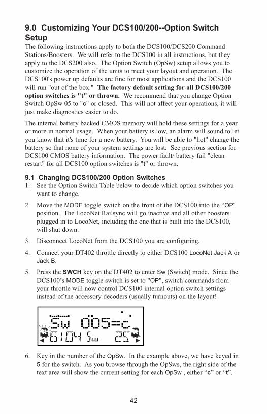
9.0 Customizing Your DCS100/200--Option Switch
SetupThe following instructions apply to both the DCS100/DCS200 Command
Stations/Boosters. We will refer to the DCS100 in all instructions, but they
apply to the DCS200 also. The Option Switch (OpSw) setup allows you to
customize the operation of the units to meet your layout and operation. The
DCS100's power up defaults are fine for most applications and the DCS100
will run "out of the box." The factory default setting for all DCS100/200
option switches is "t" or thrown. We recommend that you change Option
Switch OpSw 05 to "c" or closed. This will not affect your operations, it will
just make diagnostics easier to do.
The internal battery backed CMOS memory will hold these settings for a year
or more in normal usage. When your battery is low, an alarm will sound to let
you know that it's time for a new battery. You will be able to "hot" change the
battery so that none of your system settings are lost. See previous section for
DCS100 CMOS battery information. The power fault/ battery fail "clean
restart" for all DCS100 option switches is "t" or thrown.
9.1 Changing DCS100/200 Option Switches1. See the Option Switch Table below to decide which option switches you
want to change.
2. Move the MODE toggle switch on the front of the DCS100 into the “OP”
position. The LocoNet Railsync will go inactive and all other boosters
plugged in to LocoNet, including the one that is built into the DCS100,
will shut down.
3. Disconnect LocoNet from the DCS100 you are configuring.
4. Connect your DT402 throttle directly to either DCS100 LocoNet Jack A or
Jack B.
5. Press the SWCH key on the DT402 to enter Sw (Switch) mode. Since the
DCS100’s MODE toggle switch is set to "OP", switch commands from
your throttle will now control DCS100 internal option switch settings
instead of the accessory decoders (usually turnouts) on the layout!
6. Key in the number of the OpSw. In the example above, we have keyed in
5 for the switch. As you browse through the OpSws, the right side of the
text area will show the current setting for each OpSw , either “c” or “t”.
42
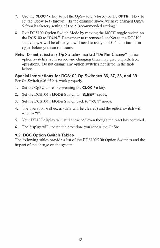
43
7. Use the CLOC / c key to set the OpSw to c (closed) or the OPTN / t key to
set the OpSw to t (thrown). In the example above we have changed OpSw
5 from its factory setting of t to c (recommended setting).
8. Exit DCS100 Option Switch Mode by moving the MODE toggle switch on
the DCS100 to “RUN.” Remember to reconnect LocoNet to the DCS100.
Track power will be off so you will need to use your DT402 to turn it on
again before you can run trains.
Note: Do not adjust any Op Switches marked “Do Not Change” These
option switches are reserved and changing them may give unpredictable
operations. Do not change any option switches not listed in the table
below.
Special Instructions for DCS100 Op Switches 36, 37, 38, and 39For Op Switch #36-#39 to work properly,
1. Set the OpSw to “c” by pressing the CLOC / c key.
2. Set the DCS100’s MODE Switch to “SLEEP” mode.
3. Set the DCS100’s MODE Switch back to “RUN” mode.
4. The operation will occur (data will be cleared) and the option switch will
reset to “t”.
5. Your DT402 display will still show “c” even though the reset has occurred.
6. The display will update the next time you access the OpSw.
9.2 DCS Option Switch TablesThe following tables provide a list of the DCS100/200 Option Switches and the
impact of the change on the system.
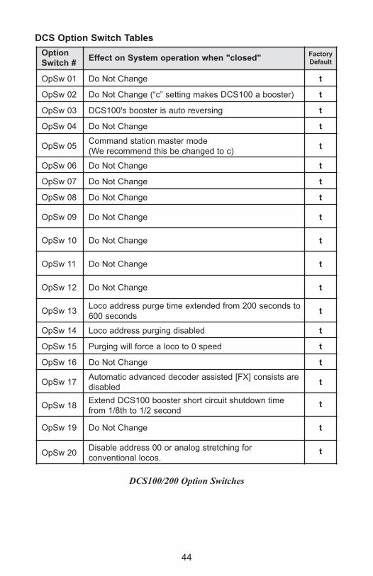
44
DCS Option Switch Tables
DCS100/200 Option Switches
Option
Switch #effect on System operation when "closed"
Factory
Default
OpSw 01 Do Not Change t
OpSw 02 Do Not Change (“c” setting makes DCS100 a booster) t
OpSw 03 DCS100's booster is auto reversing t
OpSw 04 Do Not Change t
OpSw 05Command station master mode
(We recommend this be changed to c) t
OpSw 06 Do Not Change t
OpSw 07 Do Not Change t
OpSw 08 Do Not Change t
OpSw 09 Do Not Change t
OpSw 10 Do Not Change t
OpSw 11 Do Not Change t
OpSw 12 Do Not Change t
OpSw 13Loco address purge time extended from 200 seconds to
600 secondst
OpSw 14 Loco address purging disabled t
OpSw 15 Purging will force a loco to 0 speed t
OpSw 16 Do Not Change t
OpSw 17Automatic advanced decoder assisted [FX] consists are
disabledt
OpSw 18Extend DCS100 booster short circuit shutdown time
from 1/8th to 1/2 secondt
OpSw 19 Do Not Change t
OpSw 20Disable address 00 or analog stretching for
conventional locos. t

45
* See special instructions in Section 9.1 for setting OpSw 36-39..
DCS100/200 Option Switches (Continued)
Option
Switch #effect on System operation when "closed"
Factory
Default
OpSw 21 OpSw 21-23 set the global system default type for
"NEW" loco selections. SW21/22/23 set as follows:
t-t-t = 128 step mode
t-t-c = 128 step FX mode
c-t-t = 14 step mode
c-c-t = 28 step
t
OpSw 22 t
OpSw 23 t
OpSw 24 Do Not Change t
OpSw 25 Disable aliasing t
OpSw 26 Enable routes t
OpSw 27Disable normal switch commands, a.k.a. the "Bushby
bit." Allows attached PC to handle switch control logict
OpSw 28 Disable DS54 interrogate commands at power on t
OpSw 29 Do Not Change t
OpSw 30 Do Not Change t
OpSw 31 Meter route/switch output rate when not trinary t
OpSw 32 Do Not Change t
OpSw 33 Allow track power to restore to prior state at power on t
OpSw 34Allow track to power up to run state, if set to run prior to
power ont
OpSw 35 Do Not Change t
OpSw 36* Clears all mobile decoder info & consists t
OpSw 37* Clears all routes t
OpSw 38* Clears the loco roster t
OpSw 39* Clears all internal memory states, including OpSw 36, 37
& 38 t
OpSw 40 Do Not Change t
OpSw 41Diagnostic click when valid LocoNet commands incom-
ing & routes being outputt
OpSw 42 Disable 3 beeps when loco address purged t

46
DCS100/200 Option Switches (Continued)
Option
Switch #effect on System operation when "closed"
Factory
Default
OpSw 43Disable LocoNet update of command station’s
track statust
OpSw 44Expand slot refresh area from 22 (Big Boy compatible)
to 120 t
OpSw 45 Disable reply for switch state request t
OpSw 46 Do Not Change t
OpSw 47
Program track is brake generator when not program-
ming. Braking is DCC set to speed 0 (not Emergency
stop) for address 0, light ON, broadcast to all addresses
t
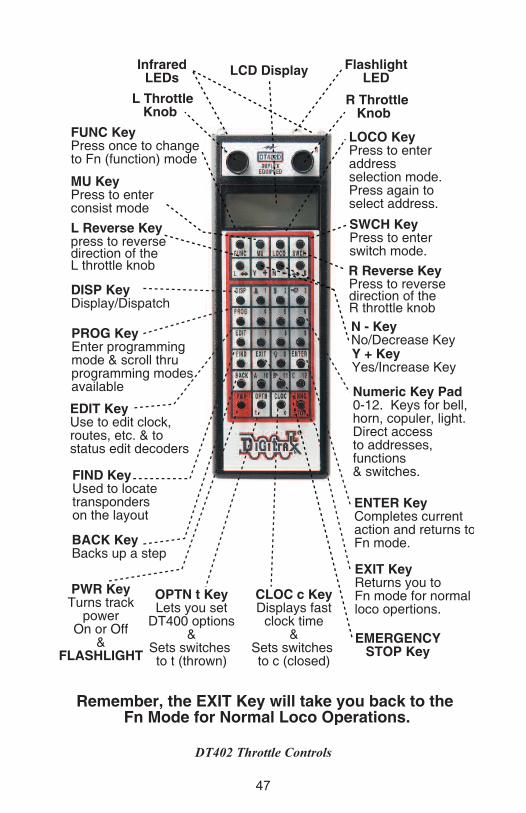
47
DT402 Throttle Controls
FUNC KeyPress once to changeto Fn (function) mode
LOCO KeyPress to enteraddressselection mode.Press again to select address.
LCD Display
press to reversedirection of theL throttle knob
MU KeyPress to enterconsist mode
L Throttle Knob
R Throttle Knob
Y + KeyYes/Increase Key
N - KeyNo/Decrease Key
EMERGENCYSTOP Key
Press to reversedirection of the R throttle knob
L Reverse Key
R Reverse Key
SWCH KeyPress to enterswitch mode.
DISP KeyDisplay/Dispatch
PROG KeyEnter programmingmode & scroll thruprogramming modesavailable
EDIT KeyUse to edit clock,routes, etc. & to status edit decoders
FIND KeyUsed to locate transponderson the layout
BACK KeyBacks up a step
EXIT KeyReturns you toFn mode for normal loco opertions.
ENTER KeyCompletes currentaction and returns toFn mode.
OPTN t KeyLets you set
DT400 options&
Sets switches to t (thrown)
CLOC c KeyDisplays fast
clock time&
Sets switches to c (closed)
PWR KeyTurns track
powerOn or Off
&FLASHLIGHT
Numeric Key Pad0-12. Keys for bell, horn, copuler, light. Direct accessto addresses, functions& switches.
Remember, the EXIT Key will take you back to the Fn Mode for Normal Loco Operations.
FlashlightLED
InfraredLEDs
48
10.0 DT402 Series Throttle Control Panel
10.1 General InformationThe DT402 series are full function hand held throttles that include 2 indepen-
dent throttles and a common keypad to control, up to 29 functions (F0-F28),
turnouts and programming. The DT402 does not require a battery in normal
walkaround operation. If you do not install a battery, the throttle display will
be off while you are unplugged from the system. We recommend that you use
a battery in all DT402s even when not required. The DT402 requires a known
good 9-volt battery for infrared operation. The DT402R and DT402D require a
known good 9-volt battery for both infrared and radio operation.
10.2 L (Left) and R (Right) Throttle knobsThroughout this manual we refer to the throttle knob on the left side as the
L Throttle and the throttle knob on the right side as the R Throttle. This corre-
sponds to the L and R that appear on the throttle.
The throttle knobs on the DT402 use “encoders.” They give very smooth, fine
speed control. In 128 speed step mode it takes four complete rotations of the
knob to go from stop to full speed. When you select a locomotive that is
already moving on either throttle knob, that throttle will continue to run the
locomotive at the same speed and in the same direction in which it was travel-
ing before being selected to the throttle.
As you turn the DT402 throttle knobs you will feel a mechanical detent (and
hear a beep if your throttle is set up for beeps and clicks). Each time you move
the knob, the system processes information. In some cases, the LCD display
will not change each time you feel the detent. In the case of increasing and
decreasing loco speed, this is because each detent does not equal an increase of
1% speed. If your DT402 is set up for ballistic tracking, the speed with which
you move the encoder will affect how the display changes.
You can customize the tracking characteristics of these knobs for either straight
line (normal) tracking or ballistic tracking. With straight line tracking each
movement of the knob causes a fixed rate of change. With ballistic tracking,
the faster you increase or decrease the throttle knob, the faster the data changes
in the throttle. Your DT402 was shipped with ballistic tracking as the factory
default setting. To change this setting see Section 16.0 (option: NoBlstic).
The throttle knobs on the DT402 can also be used to access the recall stack and
select a locomotive to run on a throttle or to reverse the direction of the loco-
motive currently selected on that throttle.
When dialing up numbers with the throttle knobs, the R Throttle knob changes
1s and 10s and the L Throttle knob changes 100s and 1000s. This makes the
throttle knobs easy to use when dialing up four digit addresses.
If you prefer larger throttle knobs, simply remove the standard 1/2” knobs by
pulling gently and replace them with larger knobs (up to 1.25”).
49
10.3 Liquid Crystal Display (LCD)
DT402 LCD
10.3.1 Loco Icon
The L and R Loco icons are used to indicate whether an address is avail-
able for selection. A blinking loco icon means that the address is available for
selection and a steady loco icon means that the loco address is currently select-
ed or in use by another throttle.
10.3.2 Direction Indicators The direction indicators are located in the LCD Display of the DT402
directly below the Loco icon. There are separate indicators for the L (left) and
R (right) throttles. If the arrow points to the front of the loco, the throttle is in
the forward direction. If the arrow points to the back of the loco, then the
throttle is in the reverse direction. If there is not a locomotive selected on a
throttle the loco icon will not appear.
= Forward Direction = Reverse Direction
Note: These direction indicators are for decoder equipped locos only. They
will indicate direction based on the normal direction of travel that you set up
for your decoder equipped loco. If you are using an analog loco, the direction
indicator may or may not match the actual direction of the analog loco.
10.3.4 Smoke IconThe Smoke Icon is located just above the Loco icon. Both the L and R Throttle
have a smoke icon. If a loco is selected on either throttle, the Loco icon will
appear beside the address of that loco. If nothing is selected, there will be no
Loco icon and the address area will show SEL. The blinking smoke icon indi-
cates which throttle is currently active (having its function states displayed in
the top line of the LCD). Since both throttles must share the keypad, only one
R Throttle DirectionIndicators
L Throtte DirectionIndicators
Text Area
Mode
Indicator
L Throttle Address
R ThrottleAddress
R Loco IconL Loco Icon
L Smoke Icon R Smoke Icon
Functions 0-12 (Active Throttle)
Tetherless Indicator Track PowerIndicator
R Semaphore
L Semaphore
R Bar GraghL Bar Graph
50
at a time can have access to the keypad and function controls. The active throt-
tle has access to the function controls and the status of the functions for the
active throttle are displayed in the top line of the LCD. To make either throttle
the active throttle simply click it once or turn the Throttle knob a little.
No Loco Icon = nothing selected on this side of the throttle
Loco with steady smoke = Keypad and function display not active
for locomotive address selected on this throttle.
Loco with flashing smoke = Keypad and function display active for
the locomotive address selected on this throttle.
10.3.4 Mode IndicatorThe mode indicator, located at the bottom center of the LCD, shows the
DT402’s current mode of operations.
The DT402 automatically defaults to the Fn mode and returns to this mode
when ever the EXIT Key is pressed. The Mode indicator usually shows
what the numeric keys are associated with. For example, in Fn mode, any
entry on the numeric keypad will affect functions. In Sw mode, keypad entries
will change turnouts and in Lo mode, entries on the keypad will enter loco
address numbers, etc.
The following table provides a list of the Mode indication displayed, the mode
name and the use of the mode by the DT402.
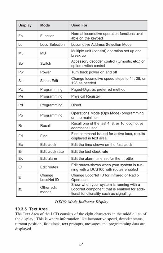
51
DT402 Mode Indicator Display
10.3.5 Text AreaThe Text Area of the LCD consists of the eight characters in the middle line of
the display. This is where information like locomotive speed, decoder status,
turnout position, fast clock, text prompts, messages and programming data are
displayed.
Display Mode Used For
Fn FunctionNormal locomotive operation functions avail-
able on the keypad
Lo Loco Selection Locomotive Address Selection Mode
Mu MUMultiple unit (consist) operation set up and
break up
SW SwitchAccessory decoder control (turnouts, etc.) or
option switch control
PW Power Turn track power on and off
SE Status EditChange locomotive speed steps to 14, 28, or
128 as needed
PG Programming Paged-Digitrax preferred method
PH Programming Physical Register
Pd Programming Direct
Po ProgrammingOperations Mode (Ops Mode) programming
on the mainline.
RE RecallRecall one of the last 4, 8, or 16 locomotive
addresses used
Fd FindFind command issued for active loco, results
displayed in text area.
Ec Edit clock Edit the time shown on the fast clock
EF Edit clock rate Edit the fast clock rate
EA Edit alarm Edit the alarm time set for the throttle
Er Edit routesEdit routes-shows when your system is run-
ning with a DCS100 with routes enabled
E1Change
LocoNet ID
Change LocoNet ID for Infrared or Radio
Operation
E?Other edit
modes
Show when your system is running with a
LocoNet component that is enabled for addi-
tional functionality such as signaling.

52
10.3.6 L (Left) and R (Right) Throttle DisplayThe decoder address selected on the L Throttle is displayed on the bottom line
of the LCD to the left of the Mode Indicator. The decoder address selected on
the R Throttle is displayed to the right of the Mode Indicator. The address can
show as either the 2-digit or the 4-digit decoder address. If no address is
selected the display will show “SEL.” If a 2-digit address is selected (00-127),
the display will show two or three digits. If a 4-digit address is selected (0128
-9983), the display will show all four digits including the leading zero.
10.3.7 L and R Bar GraphEach throttle has a bar graph located above the text area of the LCD. Each of
these indicates the speed setting of the L and R Throttles graphically from a sin-
gle dot (0% throttle) to 20 dots (full throttle). This is useful when the text area
is showing information other than speed.
2 digit address 25Selected on theL ThrottleRunning at 0% speedIn reverse.
4 Digit address 5234Selected on theR ThrottleRunning at 25% speedIn the forward directionFunctions 0, 1, & 3 on.
Track Power Indicator ON
Throttle in normal operationsmode indicated by Fn.In Function (Fn) ModeThrottle knobs control Loco'sSpeed & Direction.Keypad entries control functions.
Bar Graph showing 50% speed on R Throttle
Bar Graph showing full speed on R Throttle
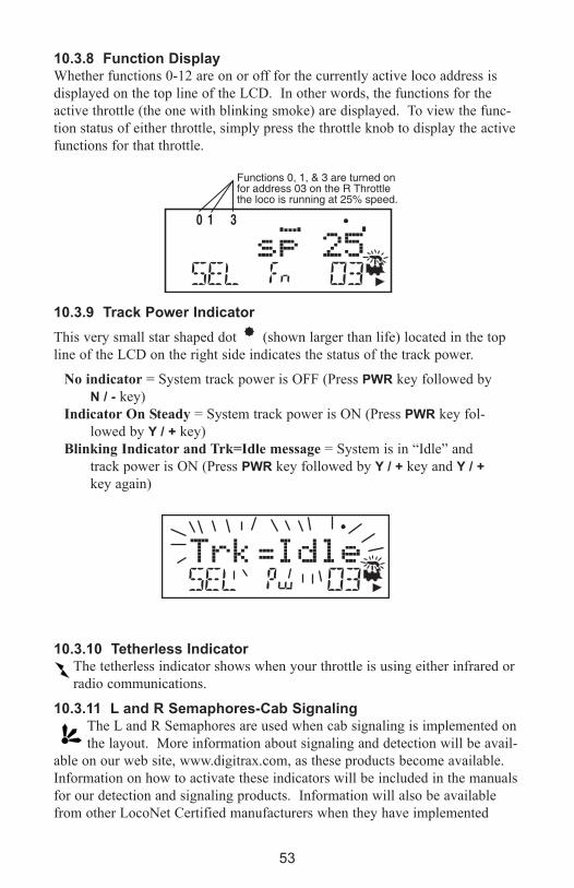
53
10.3.8 Function DisplayWhether functions 0-12 are on or off for the currently active loco address is
displayed on the top line of the LCD. In other words, the functions for the
active throttle (the one with blinking smoke) are displayed. To view the func-
tion status of either throttle, simply press the throttle knob to display the active
functions for that throttle.
10.3.9 Track Power Indicator
This very small star shaped dot (shown larger than life) located in the top
line of the LCD on the right side indicates the status of the track power.
No indicator = System track power is OFF (Press PWR key followed by
N / - key)
Indicator On Steady = System track power is ON (Press PWR key fol-
lowed by Y / + key)
Blinking Indicator and Trk=Idle message = System is in “Idle” and
track power is ON (Press PWR key followed by Y / + key and Y / +
key again)
10.3.10 Tetherless IndicatorThe tetherless indicator shows when your throttle is using either infrared or
radio communications.
10.3.11 L and R Semaphores-Cab SignalingThe L and R Semaphores are used when cab signaling is implemented on
the layout. More information about signaling and detection will be avail-
able on our web site, www.digitrax.com, as these products become available.
Information on how to activate these indicators will be included in the manuals
for our detection and signaling products. Information will also be available
from other LocoNet Certified manufacturers when they have implemented
Functions 0, 1, & 3 are turned onfor address 03 on the R Throttlethe loco is running at 25% speed.

54
these features in their software.
The L and R Semaphores will display the following:
= Clear
= Approach
= Stop
10.4 DT402 keypad
10.4.1 FUNC keyThe FUNC key is used to enter function control mode. Function control
mode is the default mode for normal locomotive operation with the
DT402. Press this key during any throttle task to return to normal loco opera-
tion mode with function controls active on the numeric keypad.
10.4.2 MU keyThe MU key is used to enter consist set up mode. Once the MU Key is
pressed, you will be prompted by the throttle to use the Y / + or N / - keys
to add locos to or remove locos from consists.
10.4.3 LOCO keyThe LOCO key is used for selecting loco addresses on to the throttles so
that the address is controlled by the throttle. Sometimes people call this
“assigning locos to throttles.”
10.4.4 SWCH keyThe SWCH key is used for entering switch control mode. Once this key is
pressed, you will be prompted to select a switch address and issue a
thrown or closed command. Switch control mode is used in normal operation
for operating turnout machines and in set up mode for setting up option switch-
es in the throttle and command station.
10.4.5 L and R Reverse keysThe L and R Reverse Keys change the direction of travel of the loco on the
related throttle when the throttle is in Fn (Normal Operation) Mode.
The ReVeRSe / R key changes direction of the address on the “R” or
Right Throttle.
The L / ReVeRSe key changes direction of the address on the “L” or Left
Throttle.
F U N CF U N C
M UM U
L O C OL O C O
S W C HS W C H
RR
LL

55
10.4.6 Y / + and N / - keysY / + key and
N / - key are used:
to turn track power on and off,
to increase or decrease loco speed.
to link and unlink locos during MU’ing.
to accomplish tasks using system editors.
These keys can be set up to act in two different ways:
Repeating (also called typematic) so that if you hold a key down it will
continue to increase or decrease step by step until you release the
key. This option is active when your throttle is set up for ballistic
tracking. Your DT402 was shipped from the factory with this fea-
ture enabled.
Single Press so that you will must press the key each time you want to
increase or decrease. This option is active when your throttle is set
up for straight line tracking.
See Section 16.0 (option: NoBlstic) for information on changing this
setting on your DT402.
10.4.7 DISP keyThe DISP key is used for displaying programming information and dis-
patching loco addresses.
10.4.8 PROG keyThe PROG key is used to enter programming mode and to toggle among
the programming modes available for use.
10.4.9 eDIT keyThe eDIT key is used to enter the Edit Mode for editing the fast clock,
routes, signaling, etc. It is also used to status edit decoders while in loco-
motive address selection mode.
10.4.10 FIND keyThe FIND key is used in conjunction with a layout instrumented for
Digitrax Transponding and locos or cars equipped with transponders to
find the location of those pieces of rolling stock on the layout.
10.4.11 BACk keyThe BACk key is used to go back one step.
Y Y ++
N
D I S PD I S P
P R O GP R O G
E D I TE D I T
F I N DF I N D
B A C KB A C K

56
10.4.12 PWR keyThe PWR key is used to enter power mode for turning layout power on
and off. Once you press this key, you will be prompted to use the Y / +
key to turn power on or the N / - key to turn power off.
The PWR key is also used to turn on and off the flashlight feature. The flash-
light LED will be on as long as you hold down the PWR key.
10.4.13 OPTN / t keyThe OPTN / t key is used to enter the Option Mode to set throttle and sys-
tem options. It is also used to issue t (thrown) commands when the throt-
tle is in Switch mode.
In the case of turnout control:
t=thrown, turnout is set for the diverging route through the curved leg.
10.4.14 CLOC / c keyThe CLOC / c key is used to toggle between displaying and not displaying
the current fast clock time. It is also used to issue c (closed) commands
when the throttle in Switch mode.
In the case of turnout control:
c=closed, turnout is set for the main line with routing through the straight
leg of the turnout.
10.4.15 eXIT keyThe eXIT key is used to exit the current throttle task without making
changes. Pressing this key will usually return the DT402 to Fn mode for
regular locomotive operation.
10.4.16 eNTeR keyThe eNTeR key is used to complete the current throttle task and return to
Fn mode for normal operations.
10.4.17 eMRG STOP keyYour DT402 comes from the factory set for “Local” Stop. When you
press the eMRG STOP key, the loco address that is active on your display
(the one with the blinking smoke) will stop. When you press the
eMRG STOP key again, the loco address on the other throttle of your DT402
will stop.
You can change the DT402’s Option Setting (ES->Idle) to set the eMRG STOP
key to “Global Stop”. (See Section 16.0.) With the Global Stop option enabled,
pressing the eMRG STOP key sets the track status to IDLE and stops all locos
on the layout. You will see the DT402’s TRACK POWER indicator blinking on
and off. To resume operations, press the PWR key followed by the Y / + key to
P W RP W R
O P T NO P T N
tt
O P T NO P T N
tt
C L O CC L O C
cc
C L O CC L O C
cc
E X I TE X I T
E N T E RE N T E R
E M R GE M R G
S T O PS T O P

57
return locos to their speed prior to the EMRG STOP. Press eXIT key to leave
Pw mode and return to Fn mode after turning track power back on with PWR
key and Y / + key.
10.4.18 Full Numeric keypadThe numeric keys on the keypad are usually related to the throttle mode shown
in the LCD’s mode indicator area. For example, when the mode is Fn, the
numeric keys are used for function control. When the mode is Lo, the numeric
keys are used to enter loco addresses. When the mode is Sw, the numeric keys
are used to enter switch addresses.
The 0-12 keys allow direct entry of loco and switch addresses as well as
Configuration variables (CVs) values during selection and programming.
These keys also give direct access to functions 0-12 during normal operation of
locos. Special number keys:
The LAMP / 0 key is most often used to turn on and off the loco’s head
lights. It can also be used for other functions as desired.
The BeLL / 1 key is most often used to turn on and off the bell sound in
locos equipped with sound decoders.
The HORN / 2 key is most often used to turn on and off the horn sound in
locos equipped with sound decoders. This function key is a momentary
key that will activate the sound as long as the key is held down. This key also
pressure sensitive to allow for the use of sound decoders that incorporate a
“playable whistle.”
The COUPLeR / 3 key is most often used to activate couplers. It can be
used for any function.
The A / 10, B / 11 and C / 12 keys make it easy to use functions
10-12 and give more flexibility for future features by providing
A, B and C as possibilities.
10.4.19 Infrared emittersYour DT402 has two infrared LEDs in the cable end of the throttle. These
emitters send infrared signals that can be used by LocoNet compatible Infrared
receivers to give you tetherless operation. See Section 14.2 for infrared opera-
tion information.
00
11
22
33
1 21 2CC1 11 1BB1 01 0AA
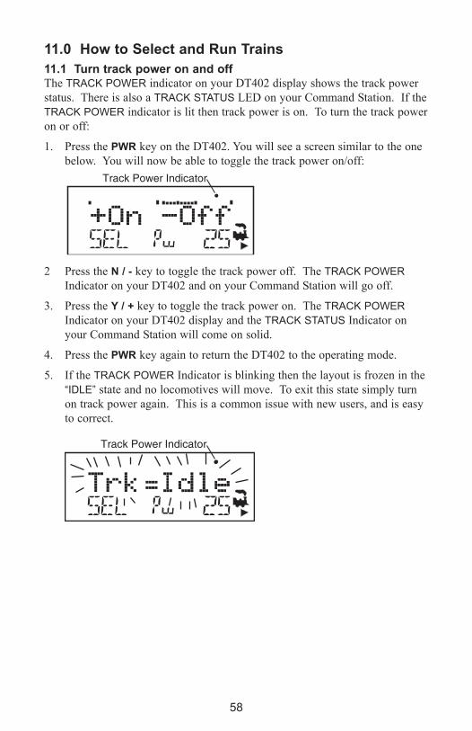
58
11.0 How to Select and Run Trains
11.1 Turn track power on and offThe TRACK POWER indicator on your DT402 display shows the track power
status. There is also a TRACK STATUS LED on your Command Station. If the
TRACK POWER indicator is lit then track power is on. To turn the track power
on or off:
1. Press the PWR key on the DT402. You will see a screen similar to the one
below. You will now be able to toggle the track power on/off:
2 Press the N / - key to toggle the track power off. The TRACK POWER
Indicator on your DT402 and on your Command Station will go off.
3. Press the Y / + key to toggle the track power on. The TRACK POWER
Indicator on your DT402 display and the TRACK STATUS Indicator on
your Command Station will come on solid.
4. Press the PWR key again to return the DT402 to the operating mode.
5. If the TRACK POWER Indicator is blinking then the layout is frozen in the
“IDLE” state and no locomotives will move. To exit this state simply turn
on track power again. This is a common issue with new users, and is easy
to correct.
Track Power Indicator
Track Power Indicator
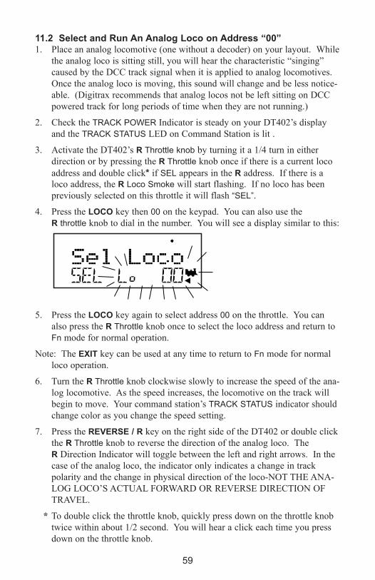
59
11.2 Select and Run An Analog Loco on Address “00”1. Place an analog locomotive (one without a decoder) on your layout. While
the analog loco is sitting still, you will hear the characteristic “singing”
caused by the DCC track signal when it is applied to analog locomotives.
Once the analog loco is moving, this sound will change and be less notice-
able. (Digitrax recommends that analog locos not be left sitting on DCC
powered track for long periods of time when they are not running.)
2. Check the TRACK POWER Indicator is steady on your DT402’s display
and the TRACK STATUS LED on Command Station is lit .
3. Activate the DT402’s R Throttle knob by turning it a 1/4 turn in either
direction or by pressing the R Throttle knob once if there is a current loco
address and double click* if SEL appears in the R address. If there is a
loco address, the R Loco Smoke will start flashing. If no loco has been
previously selected on this throttle it will flash “SEL”.
4. Press the LOCO key then 00 on the keypad. You can also use the
R throttle knob to dial in the number. You will see a display similar to this:
5. Press the LOCO key again to select address 00 on the throttle. You can
also press the R Throttle knob once to select the loco address and return to
Fn mode for normal operation.
Note: The eXIT key can be used at any time to return to Fn mode for normal
loco operation.
6. Turn the R Throttle knob clockwise slowly to increase the speed of the ana-
log locomotive. As the speed increases, the locomotive on the track will
begin to move. Your command station’s TRACK STATUS indicator should
change color as you change the speed setting.
7. Press the ReVeRSe / R key on the right side of the DT402 or double click
the R Throttle knob to reverse the direction of the analog loco. The
R Direction Indicator will toggle between the left and right arrows. In the
case of the analog loco, the indicator only indicates a change in track
polarity and the change in physical direction of the loco-NOT THE ANA-
LOG LOCO’S ACTUAL FORWARD OR REVERSE DIRECTION OF
TRAVEL.
* To double click the throttle knob, quickly press down on the throttle knob
twice within about 1/2 second. You will hear a click each time you press
down on the throttle knob.

60
11.3 Select and Run A Decoder-equipped Loco Each decoder has an address. To select a decoder-equipped locomotive and run
it on either throttle, you must know its address. Digitrax decoders are set up at
the factory with the “default” 03. This means that when you take a Digitrax
decoder out of the package and install it in your loco, you can select address 03
on your throttle and run the decoder. The first Configuration Variable (CV)
programmed by most users is the decoder’s address since it is not very useful
to have all of your locos run on address “03.”
If you do not know the address of the decoder equipped locomotive you want
to run, you can simply program the decoder’s address and select it to run using
the new, known address. See Section 16.1 and your Digitrax Decoder Users
Manual for a complete discussion of decoder addressing.
1. Place a decoder equipped locomotive on your layout.
2. Check the TRACK STATUS indicator is steady on your DT402’s display
and the Command Station TRACK STATUS LED is lit (track power on).
3. Activate the DT402’s L Throttle knob by turning it a 1/4 turn in either
direction or by pressing the L Throttle knob once if there is a current loco
address and double click if SEL appears in the L address. If there is a loco
address, the L Loco Smoke will start flashing. If no loco has been previ-
ously selected on this throttle it will flash “SEL”.
4. Press the LOCO key. The left side of the display will begin flashing. You
will see a display similar to this:
5. Use the numeric keypad to enter 03 or use the R Throttle knob to select
Address “03” in the left side of the display. (The R Throttle knob changes
1s and 10s, the L Throttle knob changes 100s and 1000s.)
6. Press the LOCO key again to select address 03 on the throttle. You can
also press the L Throttle knob once to select the loco address and return to
Fn mode for normal operation.
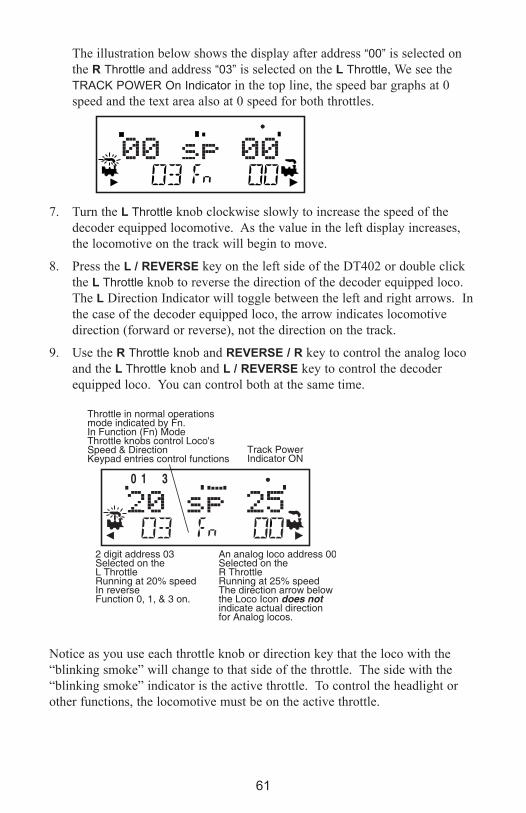
61
The illustration below shows the display after address “00” is selected on
the R Throttle and address “03” is selected on the L Throttle, We see the
TRACK POWER On Indicator in the top line, the speed bar graphs at 0
speed and the text area also at 0 speed for both throttles.
7. Turn the L Throttle knob clockwise slowly to increase the speed of the
decoder equipped locomotive. As the value in the left display increases,
the locomotive on the track will begin to move.
8. Press the L / ReVeRSe key on the left side of the DT402 or double click
the L Throttle knob to reverse the direction of the decoder equipped loco.
The L Direction Indicator will toggle between the left and right arrows. In
the case of the decoder equipped loco, the arrow indicates locomotive
direction (forward or reverse), not the direction on the track.
9. Use the R Throttle knob and ReVeRSe / R key to control the analog loco
and the L Throttle knob and L / ReVeRSe key to control the decoder
equipped loco. You can control both at the same time.
Notice as you use each throttle knob or direction key that the loco with the
“blinking smoke” will change to that side of the throttle. The side with the
“blinking smoke” indicator is the active throttle. To control the headlight or
other functions, the locomotive must be on the active throttle.
2 digit address 03Selected on theL ThrottleRunning at 20% speedIn reverseFunction 0, 1, & 3 on.
An analog loco address 00Selected on theR ThrottleRunning at 25% speedThe direction arrow belowthe Loco Icon does not indicate actual directionfor Analog locos.
Track Power Indicator ON
Throttle in normal operationsmode indicated by Fn.In Function (Fn) ModeThrottle knobs control Loco'sSpeed & DirectionKeypad entries control functions
62
11.4 Releasing An Address From A ThrottleWhen you are finished running a locomotive address, release if from your
throttle so that it is available for other throttles to select and run.
Simplex Radio and Infrared Throttles must be plugged in to LocoNet to release
an addresses from your throttle. You can disable this safety feature by setting
your DT402’s Options to allow tetherless release (See Section 15.0 for instruc-
tions). Duplex Radio throttles can release addresses without plugging in.
1. Use the throttle to make the locomotive’s speed zero (this step is optional
but strongly recommended as the loco will continue to move if speed is not
reduced to zero).
2. While the loco’s address and speed information is displayed, press the
LOCO key to go into Lo select mode. This will release the address from
your throttle immediately.
3. The address will begin to blink in the display. Press the DISP key to dis-
patch the address on the throttle and the locomotive will be released to the
system and marked as a dispatched address. The display on your DT402
will show SEL for the throttle. See Dispatching below.
4. If you press the LOCO key again, the throttle will begin flashing the
address you just released. You can re-select that address by pressing the
LOCO key or you can use the throttle knobs or key pad to browse to a new
address and select it instead.
11.5 Dispatching addresses or consistsDispatching is a special feature incorporated in the LocoNet language to meet
the needs of operators that wish to enforce a strict discipline in how operators
gain access to locomotives during an operating session. Dispatching also lets
you run consists with basic throttles that can’t set up their own consists and run
four-digit addresses on basic throttles that only have two digit capability. It lets
you have newcomers run trains on the layout without giving them access to the
entire operation.
When you dispatch a locomotive address or consist to your LocoNet system,
you make it available to be acquired by another throttle. Only one address at a
time can be marked as a dispatched address in the system. The dispatched
address can be a single locomotive address, either two digit or four digit, or a
consist that was set up by the DT402. The TOP locomotive in a consist or MU
can be dispatched to transfer control of the entire consist to another throttle.
To dispatch a locomotive address using a the DT402
1. Press the LOCO key to enter address selection, browse to the address you
want to dispatch.
2. Press the DISP key to dispatch it to your LocoNet system.!
NOTE: DT402R and DT402 throttles must be plugged in to LocoNet to dis-
patch loco addresses. DT402D does not have to be plugged in to dispatch.

63
11.6 Recall a LocoYour DT402 stores the last 4, 8, or 16 unique loco addresses used by the throt-
tle in a recall stack. Your DT402 defaults to a 4-address recall stack. See
Customizing Your Throttle Section 15.0 for information on how to change the
recall stack depth.
For example if you have your DT402 set up for an 8 deep recall stack and the
last 8 addresses you selected were: 00, 1987, 52, 0678, 03, 8819, 25, and
2500, these addresses will be in the recall stack. If you have selected any of
these addresses more than once, it will not be stored twice, only the addresses
not already stored will be added to the stack. The recall stack is not stored in
numeric order. Recall makes it convenient to select locos that you have used
previously without having to enter the address again.
To Recall the last 4, 8, or 16 addresses on the R Throttle
1. Press and hold the R Throttle knob. The word “Recall” will appear in the
text line in the middle of the display.
2. When “Recall” appears in the display, release the knob. “RE” will appear in
the mode indicator in the center of the bottom line on the display. The
right side address display will begin to flash prompting you to select a
locomotive.
3. Turn the R Throttle knob to browse through the last 4, 8, or 16 addresses
selected in the system. Whether you browse 4, 8 or 16 addresses depends
on how you set up your throttle’s options. As you browse through the
addresses, the throttle will display their current speed on the bar graph and
their status in the text line of the display. Addresses are displayed in the
order they were used by the throttle (not in numeric order).
4. Press and release the R Throttle knob or the LOCO key to select the desired
loco address. Once the locomotive is selected the R Throttle knob will be
able to control the speed control and direction of that locomotive.
Follow the same steps for recall on the L Throttle.
11.7 Stealing: Forcing An Address SelectionIf you try to select a loco address that is already selected on another throttle the
DT402 will display “Steal?=Y” in the text area. This is a safety interlock to
prevent operators from taking control of locos that are already selected on other
throttles. Occasionally it is necessary to override this interlock to gain control
of a loco that is “lost” for whatever reason. This override is called stealing and
can result in having a single loco address selected on two different throttles at
the same time.
To steal an address with the DT402:
1. Press the LOCO key to enter selection mode.
2. Enter the address of the loco you want to steal and press the LOCO key
again.

64
3. The DT402 will display “Steal?=Y” in the text area if the loco can be
stolen.
4. Press Y / + key if you want to steal.
5. Press N / - (or any other key) if you do not want to steal.
Once a throttle has “stolen” a loco address, the slot following mode becomes
active and both throttles will update speed and direction information for the
loco address. This can result in seemingly strange locomotive behavior espe-
cially if one throttle is trying to stop the loco and the other is trying to speed it
up at the same time.
When you have gained control of the stolen loco and are finished running it,
release it from your throttle by setting the loco’s speed to 0 and pressing the
LOCO key followed by the DISP or EXIT Key.
11.8 Slot FollowingWhen a DT402 detects that a loco address that is in-use on one of its throttles
is being changed by another throttle or computer, it will cause the DT402 to
“click” every time it sees a remote throttle change its locomotive settings. If
that locomotive is in the active throttle, its speed display will also show the
changes. This is called slot following. This allows two throttles to run a single
locomotive address with both throttles being able to send commands to the
loco. Both throttles will show the current speed and direction of the locomo-
tive in their displays.
Slot following is useful for training new operators. The supervisor can “steal”
a locomotive that is selected on a trainee’s throttle and be able to “look over
the trainee’s shoulder” and closely supervise that locomotive’s control. The
supervisor can gain instant override control without having to physically “grab”
the trainee’s throttle. This lets you have unskilled visitors participating and
enjoying operations without too much anxiety for either party.
Slot following also allows a computer on LocoNet to run CTC and routing con-
trol programs with automated control over locomotives. The computer can
control speed and stop engines automatically while letting the engineer with the
throttle in his hand know what is happening.
Note: Slot following does not update continuously when DT402D is used in
Duplex Power Save Mode (as shipped from the factory). For continuous slot
following updates, change Option DxRxLPwr to OFF. This will significantly
increase battery consumption when slot following is in use.
11.9 “slot=max” MessageIf the text area of the DT402 shows the message slot=max during the selection
process this means that the Command Station reached the limit of locomotive
addresses that it can manage at one time. If you want to select additional
addresses, you will need to release one or more loco addresses to continue the
selection process.

65
12.0 Stop
12.1 Setting A Loco to Zero SpeedTurn the Throttle Knob that the loco address is selected on counterclockwise
until the speed display shows 00 and the loco stops moving. This lets you slow
down your loco and stop it prototypically.
If you have set up deceleration for the loco and you move the throttle knob to
0% speed, your loco will slow down and come to a stop at the programmed
deceleration CV value. We strongly recommend that you run your locos with
the factory default of no deceleration until you are familiar with your system.
If the deceleration CV value you set for a particular loco is very large, this can
make it look like the loco is not stopping on command because the deceleration
CV value is causing the loco to take a long time to come to a stop.
12.2 emergency StopDT402s have two ways of handling an emergency stop command. This is set
up in Throttle Option Set Up. When you use emergency stop, the deceleration
rate programmed into the decoder will not have an effect and the stop will be
immediate.
12.2.1 Local Stop-Factory DefaultTo stop only the locos in the local DT402 display.
1. Press the eMRG STOP key to stop the loco that is active in the DT402’s
display. To resume operation, use the throttle knob associated with that
address to increase the loco’s speed.
2. Press the eMRG STOP key again to stop the loco that is associated with
the other throttle on the DT402. To resume operation, each operator must
use their throttle to set their loco’s speeds back to the desired speed.
12.2.2 Global Stop-Optional Setting1. See Customizing Your Throttle, Section 15.0 (option ES->Idle), for setting
the DT402 Options to use the eMRG STOP key for Emergency Stop.
2. Press the eMRG STOP key to stop all locos on the layout.
3. To resume operations, press the PWR key followed by the Y / + key again
and the locomotives will start running again at the same speed they were
running prior to STOP mode.
4. To exit PWR mode, press the PWR key or the eXIT key.
12.2.3 Track Power Off StopTo stop everything on the layout.
1. Press the PWR key followed by the N / - key while the track power is on.
This will turn track power off and will cause all locos to stop.
2. Press the PWR key followed by Y / + key again and the locomotives will
start running again at the same speed they were running prior to STOP
mode. To exit PWR mode, press the PWR key or the eXIT Key.

66
13.0 Controlling FunctionsThe DT402 Throttle will control up to 29 (F0-F28) functions when operating in
walkaround and radio mode. When operating in IR mode the DT402 throttles
will control up to 9 functions (F0-F8). The numeric keypad is always active in
the normal Fn operation mode. The functions that are currently on for the
active loco will be displayed on the top line of the DT402 display. The follow-
ing figure shows an example of how the display looks when functions 0 and 1
are turned on for loco 1652 on the R Throttle.
13.1 Controlling Functions F0-F12 1. Determine which throttle you want to control functions on and make it the
active throttle by single clicking the Throttle knob or by turning the Throttle
knob a couple of clicks.
2. If the Mode indicator in the center of the bottom line of the display
(between the loco addresses) does not show Fn, press the FUNC key once
to enter the function mode for the active throttle.
3. The DT402’s numeric keypad is always active in function mode during
normal loco operations. When the mode indicator on your DT402 shows
Fn, simply press any number on the keypad to activate or deactivate any
function from 1 to 12. The function is on for the active loco when the
function number is displayed on the top line of the display.
Function 0 (F0)Press the LAMP / 0 key to toggle F0 between on and off. Each time the
LAMP / 0 key is pressed while in function mode, F0 will change from off to on
or vice-versa. The top line of the display will display a 0 when the F0 is on
and will be blank when F0 is off. F0 is most often used for reversing head
lights but can be set up for other functions as well.
Function 2 (F2)Press the HORN / 2 key on the numeric keypad. F2 is labeled with a whistle
icon to remind you that this is the preferred function for whistle or horn opera-
tion.
F2 is a special non-latching function. This means that F2 can be used to con-
trol a whistle or horn sound from the decoder. It will only sound when F2 is
being held down. This lets you vary the length of time that the whistle blows,
just like the prototype.

67
Functions 1, 3, 4, 5, 6, 7, 8, 9, 10, 11, and 12 Press the button on the numeric keypad that corresponds with the function
number you want turn on/off. The top line of the display will display the num-
bers of the functions that are on for the active loco address.
F1 is labeled with a bell icon to remind you that this is the preferred function
for bell operation and F3 is labeled with a coupler icon to remind you that its
preferred function is coupler operation.
Note: DT402 may process functions slightly differently depending on com-
mand station capabilities.
13.2 Controlling expanded Functions F13-F19The DT402 series throttles can address additional functions F13-F28. To
address the upper function ranges, the throttle design incorporates a ‘+10’ and
‘+20’ key action. These keys, along with the standard numeric keypad, permit
the full function range to be addressed. Here’s how it’s done:
1. While holding the FUNC key down, press the 1 key then release both keys
simultaneously. The throttle will go into the ‘+10’ mode and display will
show the following:
2. Select the second digit from the throttle’s numeric keypad and you’re done.
Example: To turn on function 18, just hold the FUNC key down while press-
ing the 1 key then releasing both keys simultaneously. Next press the 8
key to turn on function 18. Just press the 8 key again to toggle off. The
figure ‘8’ on the top line of the display will toggle on and off as will the
locomotive’s function.
3. Press the FUNC key once to exit the ‘+10’ function mode and return to the
normal single digit function address mode. Please Note that you will have
to return to the ‘+10’ mode in order check whether any functions in the
+10 range are active.

68
13.3 Controlling Functions 20-28 1. While holding the FUNC key down, press the 2 Key then release both
keys simultaneously. The throttle will go into the ‘+20’ mode and display
will show the following:
2. Select the second digit from the throttle’s numeric keypad and you’re done.
Example: So if you want to turn on function 27, just hold the FUNC key
down while pressing the 2 key then releasing both keys simultaneously.
Next press the 7 key. That’s it. You’ve just turned function 27 on.
3. Press the FUNC key once to exit the ‘+20’ function mode and return to the
normal single digit function address mode. Note that you will have to
return to the ‘+20’ mode to check whether any functions in the +20 range
are active.
13.4 Controlling Functions On Consisted Locomotives Even though an individual locomotive is part of a consist and you can’t control
its speed and direction separately from the consist, you can still control its
function outputs independently as follows:
1. Press the LOCO key and select the address of the locomotive that is a part
of a consist for which you want to control functions.
2. Press the LOCO key again to select the loco address on your throttle. The
speed value will show “cn” to remind you that you can only control func-
tions on the loco and not its speed.
3. Use the steps described in Controlling Functions Sections 13.1 through
13.3 to turn on or off the functions on the consisted loco.

69
14.0 Tetherless Operation
14.1 General Tetherless OperationsAll DT402s can operate with out plugging in to LocoNet. This allows you to
disconnect from the LocoNet and still control your locomotives while walking
around your layout.
�The DT402/402R/402D are all “InfraReady.” All come with IR LEDs that
send infrared signals to the layout. To use this InfraReady capability, you
just need to install one or more infrared capable receivers (UR90, UR91 or
UR92) on your layout. You’ll also need a new or known good 9-volt bat-
tery installed in the throttle.
�The DT402R is a simplex radio equipped throttle. To use your DT402R as
a simplex radio throttle, you will need to install a UR91 simplex radio
receiver on your layout. You’ll also need to install a new or known good
9-volt battery in the throttle.
�The DT402D is a duplex radio equipped throttle. To use your DT402D as
a duplex radio throttle, you will need to install a UR92 duplex radio
transceiver on your layout and a new or known good 9-volt battery in the
throttle.
14.1.1 Selecting a Locomotive-Safety SelectionWhile tetherless, the DT402 (IR only), DT402R (IR and Radio) and DT402D
(IR only) operate as one-way transmitters. In these cases, the DT402, DT402R
& DT402D (in IR mode) must be plugged into LocoNet to select an available
locomotive address. After an address is selected, you can unplug from
LocoNet and run the selected addresses with infrared or radio. The throttle will
automatically convert to infrared or radio operation, all speed, direction, func-
tion, operations mode programming, and switch commands.
The DT402D throttle has full duplex capabilities. Once the DT402D has been
configured to communicate in duplex mode with a UR92, the full functionality
of the 402 series throttles can be enjoyed without ever plugging in to the lay-
out, including joining a Duplex Group, programming decoders, selecting, run-
ning and releasing locomotives and other layout features.
14.1.2 Releasing An Address Using IR or Simplex RadioReleasing a locomotive address makes it available for use by other throttles in
the system. Two options are available for tetherless release. These options are
set by DT402 Option setup, see Customizing Your Throttle, Section 16.0.
No tetherless release allowed: if the LOCO key is pressed while the DT402/R
is running in tetherless mode, the addresses selected will not be released unless
the throttle is plugged in to LocoNet. This is the factory default, but can be
changed in the throttle’s option setup (see Section 16.0).
Tetherless release allowed: if the LOCO key is pressed while the DT402 and
402R are running in tetherless mode, the address selected on that side of the

70
throttle will be released immediately and that throttle will become inactive. To
re-select this loco address plug your DT402/R in to LocoNet and select the
loco address on the throttle.
14.1.3 Multiple Unit OperationsConsists must be assembled and broken up while the DT402/R is plugged in to
LocoNet. MU operations are locked out while the DT402/R is running tether-
less. Once a consist is assembled, it can be operated normally using the
DT402/R in tetherless mode.
14.1.4 Programming while tetherlessOps mode programming is the only programming method that will work while
the DT402R is operating as a simplex radio throttle. If you press the PROG
key to enter programming mode, the DT402 running as tetherless will default
to the Po mode (ops mode programming). The DT402 must be connected to
LocoNet to use service mode programming and access any of the other pro-
gramming modes available. Duplex throttles can program without plugging in
any mode.
14.1.5 Switch ModeThe DT402 will operate in Sw mode while tetherless. It can operate turnouts
and routes using the OPTN / t and CLOC / c keys in the normal manner.
14.1.6 Ballistic TrackingWhile running tetherless, ballistic tracking will feel slightly different from
when the throttle is connected to LocoNet.
14.1.7 Fast Clock When using the fast clock option, the DT402/R will keep track of and display
fast time based on the last synchronized system fast time when the DT402/R
was connected to LocoNet. If the fast time is edited by another throttle con-
nected to LocoNet, the DT402/R will not see this change until it is plugged
into LocoNet at which time its display will be updated.
14.1.8 Throttle keypad Lock While the DT402/R/D are being used tetherlessly, there are occasions when
you may want to disable the throttle’s controls to prevent accidental commands
being sent to the railroad. For example, your train is in a siding waiting for
another train to pass. You put your throttle in your pocket and go take a break.
By locking the throttle controls, you will not be able to accidentally start your
train if you bump your throttle knob or press the Y / + key.
To lock/unlock the controls on your DT4021. Press both the Y / + and the N / - keys at the same time. When you are
locking the keypad be sure to press both the Y / + and N / - keys AT THE
SAME TIME to avoid sending a speed command to the active loco.
2. The throttle will display “Lock=+&-” in the display and none of the controls
will function until you unlock them.
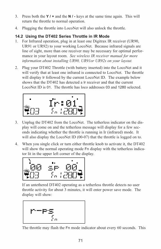
71
3. Press both the Y / + and the N / - keys at the same time again. This will
return the throttle to normal operation.
4. Plugging the throttle into LocoNet will also unlock the throttle.
14.2 Using the DT402 Series Throttle in IR Mode1. For Infrared operation, plug in at least one Digitrax IR receiver (UR90,
UR91 or UR92) to your working LocoNet. Because infrared signals are
line of sight, more than one receiver may be necessary for optimal perfor-
mance in your layout room. See wireless IR receiver manual for more
information about installing UR90, UR91or UR92s on your layout.
2. Plug your DT402 Throttle (with battery inserted) into the LocoNet and it
will verify that at least one infrared is connected to LocoNet. The throttle
will display Ir followed by the current LocoNet ID. The example below
shows that the DT402 has detected a Ir receiver and that the current
LocoNet ID is 01. The throttle has loco addresses 03 and 1280 selected.
3. Unplug the DT402 from the LocoNet. The tetherless indicator on the dis-
play will come on and the tetherless message will display for a few sec-
onds indicating whether the throttle is running in Ir (infrared) mode. It
will also display the LocoNet ID (00-07) that the throttle is logged on to.
4. When you single click or turn either throttle knob to activate it, the DT402
will show the normal operating mode Fn display with the tetherless indica-
tor lit in the upper left corner of the display.
If an untethered DT402 operating as a tetherless throttle detects no user
throttle activity for about 3 minutes, it will enter power save mode. The
display will show:
The throttle may flash the Fn mode indicator about every 60 seconds. This
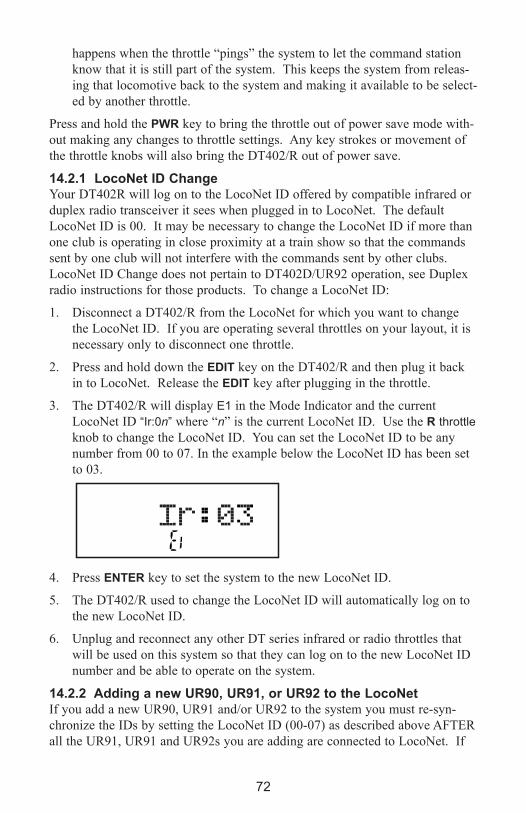
72
happens when the throttle “pings” the system to let the command station
know that it is still part of the system. This keeps the system from releas-
ing that locomotive back to the system and making it available to be select-
ed by another throttle.
Press and hold the PWR key to bring the throttle out of power save mode with-
out making any changes to throttle settings. Any key strokes or movement of
the throttle knobs will also bring the DT402/R out of power save.
14.2.1 LocoNet ID ChangeYour DT402R will log on to the LocoNet ID offered by compatible infrared or
duplex radio transceiver it sees when plugged in to LocoNet. The default
LocoNet ID is 00. It may be necessary to change the LocoNet ID if more than
one club is operating in close proximity at a train show so that the commands
sent by one club will not interfere with the commands sent by other clubs.
LocoNet ID Change does not pertain to DT402D/UR92 operation, see Duplex
radio instructions for those products. To change a LocoNet ID:
1. Disconnect a DT402/R from the LocoNet for which you want to change
the LocoNet ID. If you are operating several throttles on your layout, it is
necessary only to disconnect one throttle.
2. Press and hold down the eDIT key on the DT402/R and then plug it back
in to LocoNet. Release the eDIT key after plugging in the throttle.
3. The DT402/R will display E1 in the Mode Indicator and the current
LocoNet ID “Ir:0n” where “n” is the current LocoNet ID. Use the R throttle
knob to change the LocoNet ID. You can set the LocoNet ID to be any
number from 00 to 07. In the example below the LocoNet ID has been set
to 03.
4. Press eNTeR key to set the system to the new LocoNet ID.
5. The DT402/R used to change the LocoNet ID will automatically log on to
the new LocoNet ID.
6. Unplug and reconnect any other DT series infrared or radio throttles that
will be used on this system so that they can log on to the new LocoNet ID
number and be able to operate on the system.
14.2.2 Adding a new UR90, UR91, or UR92 to the LocoNetIf you add a new UR90, UR91 and/or UR92 to the system you must re-syn-
chronize the IDs by setting the LocoNet ID (00-07) as described above AFTER
all the UR91, UR91 and UR92s you are adding are connected to LocoNet. If
The DT400 is ready to Edit
t
t

you are operating in an area where more than one LocoNet system is operating
nearby, be sure to coordinate with other layouts so that each one has its own
unique LocoNet ID before beginning operations.
14.3 Using the DT402R in Simplex Radio Mode 1. For Radio operation with the DT402R, plug in at least one Digitrax
Simplex Radio receiver UR91 to your working LocoNet. Most layouts
only need one UR91. See the manual with your wireless receiver for more
information about installing UR91s on your layout.
2. Plug your DT402R (with good battery inserted) into the LocoNet and it
will verify that at least simplex radio receiver is connected to LocoNet.
The throttle will display rA followed by the current LocoNet ID. This
example shows that the DT402R has detected a simplex radio receiver and
that the current LocoNet ID is 01. The throttle has loco addresses 03 and
1280 selected.
3. Unplug the DT402R from the LocoNet. The tetherless indicator on the
display will come on and the tetherless message will display for a few sec-
onds indicating whether the throttle is running in rA (radio) mode. It will
also display the LocoNet ID (00-07) that the throttle is logged on to.
4. When you single click or turn either throttle knob to activate it, the
DT402R will show the normal operating mode Fn display with the tether-
less indicator lit in the upper left corner of the display.
If an untethered DT402R operating as a tetherless throttle detects no user throt-
tle activity for about 3 minutes, it will enter power save mode. You will see:
The throttle may flash the Fn mode indicator about every 60 seconds. This
73

74
happens when the throttle “pings” the system to let the command station know
that it is still part of the system. This keeps the system from releasing that
locomotive back to the system and making it available to be selected by anoth-
er throttle.
Press and hold the PWR key to bring the throttle out of power save mode with-
out making any changes to throttle settings. Any key strokes or movement of
the throttle knobs will also bring the DT402/R out of power save.
Note: Fast clock caution. If you use power save mode, the DT402’s local fast
clock copy will deviate from the LocoNet system clock. The fast clock
will re-synchronize with your LocoNet system fast clock when it is
plugged in again.
14.4 Using the DT402D Throttle in Duplex Radio ModeThere are three elements involved in duplex radio operation between the
DT402D and the UR92: Duplex Group Name, Duplex Channel, and Duplex
Group Password. These elements can be configured to provide a unique con-
nection when operating in a multisystem environment.
See the Quick Start guide on Section 2.0 for setting up the UR 92 and Joining
the DT402D to the Duplex Group. There are several additional operation and
configuration options for the Duplex Group covered below.
14.4.1 join a Duplex Group In Duplex Radio ModeThe DT402D will remember the last Duplex Group that it joined and display
that Group Name upon startup. If the Duplex Group is available, the DT402D
will rejoin the Group. If the Group is not available, you will get an Idle screen.
To select a Group, follow these instructions
1. Make sure there is a battery installed in the DT402D. Press the OPT / t
key. (If you are starting from the Idle screen hold the key down for 3 sec-
onds to power up the Throttle.) You will see:
2. Press the FIND key to display the rf search mode and scan the last active
channel. ScanNets will briefly appear on the display and if there is no
Group available on the last Channel used (19 in our example) you will see:
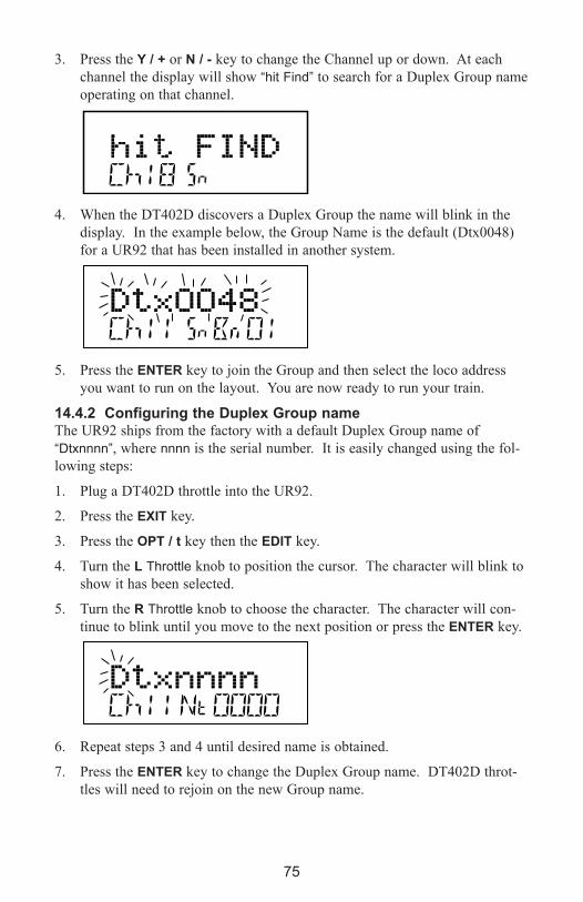
75
3. Press the Y / + or N / - key to change the Channel up or down. At each
channel the display will show “hit Find” to search for a Duplex Group name
operating on that channel.
4. When the DT402D discovers a Duplex Group the name will blink in the
display. In the example below, the Group Name is the default (Dtx0048)
for a UR92 that has been installed in another system.
5. Press the eNTeR key to join the Group and then select the loco address
you want to run on the layout. You are now ready to run your train.
14.4.2 Configuring the Duplex Group nameThe UR92 ships from the factory with a default Duplex Group name of
“Dtxnnnn”, where nnnn is the serial number. It is easily changed using the fol-
lowing steps:
1. Plug a DT402D throttle into the UR92.
2. Press the eXIT key.
3. Press the OPT / t key then the eDIT key.
4. Turn the L Throttle knob to position the cursor. The character will blink to
show it has been selected.
5. Turn the R Throttle knob to choose the character. The character will con-
tinue to blink until you move to the next position or press the eNTeR key.
6. Repeat steps 3 and 4 until desired name is obtained.
7. Press the eNTeR key to change the Duplex Group name. DT402D throt-
tles will need to rejoin on the new Group name.
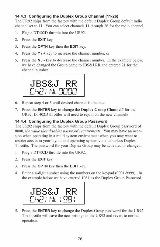
76
14.4.3 Configuring the Duplex Group Channel (11-26)The UR92 ships from the factory with the default Duplex Group default radio
channel set to 11. You can select channels 11 through 26 for the radio channel.
1. Plug a DT402D throttle into the UR92.
2. Press the eXIT key.
3. Press the OPTN key then the eDIT key.
4. Press the Y / + key to increase the channel number, or
5. Press the N / - key to decrease the channel number. In the example below,
we have changed the Group name to JBS&J RR and entered 21 for the
channel number.
6. Repeat step 4 or 5 until desired channel is obtained
7. Press the eNTeR key to change the Duplex Group Channel# for the
UR92. DT402D throttles will need to rejoin on the new channel#
14.4.4 Configuring the Duplex Group PasswordThe UR92 ships from the factory with the default Duplex Group password of
0000, the value that disables password requirements. You may have an occa-
sion when operating in a multi system environment when you may want to
restrict access to your layout and operating system via a tetherless Duplex
Throttle. The password for your Duplex Group may be activated or changed:
1 Plug a DT402D throttle into the UR92.
2. Press the eXIT key.
3. Press the OPTN key then the eDIT key.
4. Enter a 4-digit number using the numbers on the keypad (0001-9999). In
the example below we have entered 1981 as the Duplex Group Password.
5. Press the eNTeR key to change the Duplex Group password for the UR92.
The throttle will save the new settings in the UR92 and revert to normal
operation.
77
15.0 Advanced Operations Capabilities
15.1 Multiple Unit OperationsDigitrax command stations offers three methods of consist control:
1. Basic Consisting
2. Advanced Consisting
3. UniVersal Consisting (the Digitrax preferred method)
By definition, Digitrax always adds loco addresses to the “TOP” loco
address in a consist.
The “TOP” loco is special, in that it is the address that receives the speed
and direction commands for the entire consist.
All non TOP loco addresses added to the consist are controlled by com-
mands sent to the “TOP” loco.
The TOP locomotive does not have to be a physical loco on the track, it
can be a phantom.
Digitrax defines the TOP loco as the loco on the R Throttle Knob at the
time when the MU add is performed.
All loco addresses in a consist will have the same status as the TOP loco.
They will all be common, in-use or idle based on the state of the
TOP loco.
Each loco within a consist maintains its original advanced 28/128 or
standard 14 speed step mode setting.
A consist can be released by one throttle and then selected and run by
any other throttle.
A consist TOP address can be dispatched and acquired on another throttle
just like any other address. See Section 11.0.
15.1.1 Adding a Locomotive To A ConsistDT402 and DT402R throttles must be plugged in to LocoNet to add loco
addresses to consists. DT402D may perform this without plugging in.
1. Select the loco address of the TOP loco on the R Throttle knob.
2. Select the address of the loco you want to consist to the TOP loco on the
L Throttle knob.
3. Move the two locomotives into position. The locomotives can be headed
in either direction. They can be adjacent to each other in the train or one
unit can be the mid train helper or a pusher on the end of the train.
4. Before consisting the locos, make sure that both are traveling in the SAME
PHYSICAL DIRECTION ON THE TRACK. (The direction indicators
may or may not match, the important thing is that the locomotives are set
up to move in the same direction and are not pulling against each other.)

78
5. Press the MU key, the display will show the following:
the MU mode indicator on the display is lit. The loco address in the L side
of the display will blink to show that it is the address that will be consisted
to the address on the R Throttle.
6. The DT402 display will prompt you to press the Y / + key to add the loco
address or the N / - key to remove the loco address from the consist con-
trolled by the TOP loco address selected on the R Throttle. You will see
the display alternate between the following two screens to remind you of
which key to press.
7. Press the Y / + key to add the left address to the consist.
The L Throttle display shows the address of the loco that was added to the
consist with a cn in the text line above it. The R Throttle display shows the
address of the TOP loco address and its current % of full speed. The
R Throttle is now in control of the speed and direction of both locomotives
in the consist.
8. Once a consist is set up and linked to the TOP locomotive, this TOP loco
can be released and selected to run from either throttle on your DT402.
The consist can also be dispatched to another throttle.
You can access the functions of any loco in the consist by selecting the consist-
ed loco to a throttle and using the function keystrokes outlined in Section 13.0.
You will not be able to change the speed or direction of any loco that is part of
a consist but is not the TOP loco, while it is consisted.
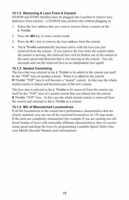
79
15.1.2 Removing A Loco From A ConsistDT402R and DT402 throttles must be plugged into LocoNet to remove loco
addresses from consists. A DT402D may perform this without plugging in.
1. Select the loco address that you want to remove from a consist on the
L Throttle.
2. Press the MU key to enter consist mode.
3. Press the N / - key to remove the loco address from the consist.
4. The L Throttle automatically becomes active with the loco you just
removed from the consist. If you remove the loco from the consist while
the consist is moving, the removed loco will be broken out of the consist at
the same speed and direction that it was moving in the consist. You can
uncouple and run the removed loco as an independent loco again!
15.1.3 Nested ConsistingThe loco that was selected in the L Throttle to be added to the consist can itself
be the “TOP” loco of another consist. When it is added to the current
R Throttle “TOP” loco it will become a “nested” consist. In this case the whole
nested consist is linked and becomes part of the new consist.
The loco that is selected in the L Throttle to be removed from the consist can
itself be the “TOP” loco of a nested consist that was linked into the current
R Throttle “TOP” loco. In this case the whole nested consist is removed from
the consist and returned to the L Throttle as a consist.
15.1.4 MU of Mismatched LocomotivesIf all the locomotives in the consist have performance characteristics that are
closely matched, you can run all the consisted locomotives in 128 step mode.
If the units are completely mismatched (for example if you are running two dif-
ferent brands of locos with noticeably different characteristics), then we recom-
mend speed matching the locos by programming Loadable Speed Tables (See
your Mobile Decoder Manual more information).

80
15.2 Sw (Switch) ModeSwitch mode is used for sending commands to accessory decoders and for
changing option switches in your LocoNet system. The most common use of
switch mode is for operating turnouts. When you enter Switch mode, the throt-
tle knobs and direction keys will continue to control the loco addresses running
on the throttle. Loco speed will be displayed on the bar graph and loco direc-
tion will be displayed on the direction indicators for each throttle.
15.2.1 To change the position of a switch or turnout1 Press the SWCH key to enter Sw (switch) mode.
2. The last switch decoder address selected by your throttle is displayed on
the text line followed by a “t” or “c”.
3 The display indicates the switch position using the “t” or “c” as follows:
“t” indicates that the switch is “thrown”
(for a turnout, the diverging route is set)
“c” indicates that the switch is “closed”
(for a turnout, the mainline route is set)
If the “t” or “c” indicator is flashing it means that the LocoNet Command
Station does not know the current switch position. A steady “t” or “c” indi-
cates that the command station knows the position of the switch.
4. Use the numeric keypad to enter switch number and the OPTN / t and
CLOC / c keys are used to tell the switch in which direction it should oper-
ate. Use the numeric keypad to enter the switch address you want to
change.
5. Once the desired switch address appears in the text area of the throttle, you
will see either “t” or “c”” on the right side of the = sign in the display. If
the “t” or “c” is flashing, the command station does not know the position
for this turnout. Press the OPTN / t key to move the switch to the
“thrown” position OR the CLOC / c key to move it to the “closed” posi-
tion.
6. If the switch you selected is a turnout connected to an accessory decoder, it
will change position from closed to thrown or vice-versa. If the switch
you selected is an option switch setting for your command station, the soft-
ware switch inside the command station will be changed.
S
S
.
3 Address 6
Address 6104 is running at 5
Address 25 is running on the R throttle at

81
7. After commanding the switch “closed” or “thrown” the switch position
display will stop flashing, since the command station now knows the cur-
rent switch position.
8. When you have finished your Sw (switch) operations you can return to Fn
(Normal Operating Mode) by pressing the eXIT key or the FUNC key .
9. The next time you enter Sw mode, the DT402 will remember where you
left off and start at the last switch address and position you accessed.
Note: that the accessory decoders in the system are accessible to all throttles or
control devices with switch control capabilities and are not reserved in-use
to a single throttle like locomotive decoders.
15.3 Fast ClockThe DT402 throttle can edit system functions like the fast clock and routes.
Both of these features can be enabled or disabled by your command station.
Digitrax command stations ship with fast clock enabled and routes disabled.
15.3.1 Fast Clock BasicsMany operators use a fast clock during operating sessions to simulate prototyp-
ical operations. Traditionally, this clock is on the wall and is set up to run at a
faster than normal rate. LocoNet has its own networked fast clock for all
Digitrax throttles connected to your system.
The fast clock display is a 4 digit 12 or 24 Hour format clock. To display the
fast clock simply press the CLOC / c key. The fast clock display will remain
active while you are running trains until you initiate another throttle task such
as loco address selection, programming, MU, Switch mode, etc. To stop dis-
playing the fast clock and return to the default display, press the CLOC / c key
again. This is the display you will see:
Any DT series throttle (including your DT402) that is plugged in to your
LocoNet system will update its fast clock time and rate to be synchronized to
the rest of the system a couple of seconds after it is connected to LocoNet.
Each DT402 can be set up with an alarm. When the current fast clock time
matches the private alarm time set in any DT402, that DT402 will beep and
flash the message “Alarm” to indicate that the alarm time has elapsed.
The fast clock rate for the fast clock is user selectable from 1:1 to 100:1 in
steps of 1. The most popular range of values is 4:1 to 8:1.
Address 6104 running at 25% speed on
Address 25 running at 75% speed on

82
15.3.2 Stop the Fast ClockSetting the clock rate to 00 will stop the fast clock for the entire system at the
currently displayed time. Fast time will re-start when a new non-zero rate
value is set.
The current fast clock time, fast clock rate and the DT402 alarm time can be
changed by using the Edit mode.
15.3.3 edit Fast Clock Time, Rate and AlarmDT402 must be plugged in to LocoNet to edit the fast clock settings.
1. From Fn mode, press the eDIT key to change to Edit Mode.
2. Press the eDIT key to scroll through the different things you can edit.
3. The first time you press the eDIT key, the mode indicator in the center of
the bottom row of the display will show Ec (Edit Clock Mode) and the text
area will show a 12 hour time. See Customizing Your Throttle,
Section 16.0 (12HrClock) for setting the clock for 12 or 24 hour operation.
4. Use the Throttle knobs to dial up the “current” time. Use the L Throttle for
hours and the R Throttle for minutes. You can only move time forward.
Press the eDIT key again to set the time and move on to edit the fast clock
rate.
5. When you press the eDIT key the second time, the mode indicator will dis-
play Ef (Edit Fast Rate) and the text will show Rate=nnn where nnn is the
clock rate. Use the throttle knobs to dial up a clock rate that is between
000 and 120 (the throttle will let you dial up to 255 in this case but values
above 120 have no meaning to the system). Press the eDIT key again to
set the fast clock rate and move on to edit the throttle alarm time.
6. Once the time and fast clock rate are set, the mode indicator will display
EA (Edit Alarm) and the text will show a 12 or 24 hour time. Use the
throttle knobs to dial up the alarm time. Press the eDIT key again to set
the fast clock alarm. NOTE: The fast clock alarm can’t be turned off.
7. Once the time, fast clock rate and alarm are set, you will automatically
return to Fn Mode unless your system is enabled for other types of editing
such as routes. If you are set up for command station routes, the clock
editing screens will be followed by Er for editing routes as described in the
system manual for command stations that support internal routes. To exit
Edit mode at any time simply press the eXIT key.

83
15.4 Route BasicsYou can use your DT402 with a DCS100 to set up routes that are triggered by
operating a single turnout address to make it either c (closed) or t (thrown).
Setting up and operating routes is similar to consisting locomotives because
you can cause more than one unit to operate based on a single command sent to
the system. We call the turnout address to which other turnout addresses are
“consisted” to the TOP address. To operate a route, use Sw (Switch) mode to
select the TOP turnout address in the route and move it to either c (closed) or
t (thrown) to initiate the route you have previously set up in your route list.
The TOP turnout address does not need to be physically present on the layout,
it can be a "phantom" turnout address.
The DCS100 supports up to 32 routes. Each route consists of a list that con-
tains a TOP turnout address and its position c or t and up to 7 other turnout
addresses and their positions. Routes are stored in the DCS100’s memory and
can be operated by any throttle in the system that can send switch commands.
Each of these 32 routes is operated by setting the TOP turnout address to the
position saved in the route list. When a route is triggered, a route can include a
switch that is the Top of another route and all the entries in the second route
will be added to the string of turnout commands the initial route request gener-
ates. The second route called is a "nested" route.
From the initial route you can "nest" up to 3 levels deep. Note that a route that
itself does not contain another Top switch (i.e., another route) will not increase
the nest depth. Knowing this, you can assemble up to 120 switch commands in
a single route if you are careful when you set up your nesting.
If the DCS100 determines that you have exceeded these limits, it will beep 5
times to alert you to the problem. Note that if a route contains the same switch
command more than once and this causes the route to "loop back" on itself, this
will also generate a 5 beep route error indication and no switch commands will
be issued to the layout. In this case you will need to edit the route and correct
the errors in the list before trying the command again.
15.4.1 enabling Routes Before you can set up routes, you must set the DCS100’s OpSw #26 to c
(closed). See your DCS100 manual for instructions for changing OpSws.
You can erase all current routes in the DCS100 by setting OpSw 37 to c
(closed).
15.4.2 external RoutesThe DS64 stationary decoder can also generate cascade switch message com-
mands or routes independently of the DCS100’s capability. See the appropriate
manuals of these products for further details.

84
15.4.3 edit RoutesTo go to the Edit Routes (Er) mode you must pass through the clock editor:
1. Start in Fn mode. Press the eDIT key to enter Edit Mode.
Press the eDIT key again to enter Ec (Edit Clock) mode.
Press the eDIT key again to enter EF (Edit Fast Rate) mode.
Press the eDIT key again to enter EA (Edit Alarm) mode.
Press the eDIT key again to enter Er (Edit Routes) mode.
The DT402’s display will show the following screen when you enter the
Edit Routes mode.
This display shows Er (Edit Routes) in the Mode Indicator area on the bot-
tom row to let you know you are in Edit Routes mode.
The right side of the bottom row shows which route you are working with.
This can be any number from 01 through 32.
The left side of the bottom row of the display shows which entry within
the route you are working with. The En (entry) number can be any number
from 01 through 08.
En01 is the TOP or controlling turnout address. The position, “t” or “c” ,
that you set for this turnout address is the one that will operate the route.
The text area shows “Sw empty” to let you know that nothing has been
entered for Entry 01, Route 01.
2. Use the R Throttle knob to dial up the Route number you want to work
with. The bottom right display will show the route number. The DT402
will allow you to dial up above route 32 but please DO NOT USE route
numbers outside the range of 01-32.
3. Use the L Throttle knob to dial up the Entry number within the chosen
route that you wish to work with. The bottom left display will show the
entry number.
This display shows Entry 01, Route 11 as empty.

85
4. Press the eNTeR key and “Sw” in the text area will begin to flash, use the
Throttle knobs to dial up the turnout address you want to add to the route.
Use the L Throttle knob for 100s and the R Throttle knob for 10s and 1s.
Once you make changes to the turnout address number or the position of
that address, the entire text area will begin to flash. The key pad is not
active during this throttle task even though some keys may change the dis-
play.
5. When the turnout address you want is on the screen use the OPTN / t key to
set the turnout to t (thrown) or the CLOC / c key to set the turnout to
c (closed).
This display shows Entry 01, Route 11 with turnout address 005 set for
c (closed). In this case address 005 is the TOP address for this route
because it is Entry 01 for the Route.
6. If you don’t want to make any changes to the route and entry selected, sim-
ply press the BACk key or either of the Throttle knobs to exit turnout
address/position editing and return to selecting a different route/entry num-
ber (step 2 above).
7. Once your selection is complete, press the eNTeR key to save the turnout
address in the position selected into the route.
8. Continue entering route entries in this manner until your route is complete.
You can toggle back and forth between selecting route and entry numbers
and entering turnout addresses and positions by pressing either Throttle
knob or the BACk key.
9. Once you have finished editing routes, press the eXIT key to exit the Er
(Edit Routes) mode and return to Fn (Normal Operating) mode.
10. To operate the routes that you have set up, simply press the SWCH key ,
key in or dial up the TOP turnout address for the route and press the
OPTN / t key or the CLOC / c key to issue the appropriate t (thrown) or
c (closed) command. When you select the TOP turnout address in a route
and the position command (c or t) you issue matches the position that is
stored in the route, the route will operate. If you select the opposite posi-
tion from that stored as the route, the TOP turnout address will change to
that position and the route will not operate.

86
15.5 FIND key and Digitrax TranspondingOn layouts set up for Digitrax transponding with transponders in locos and
rolling stock and transponder receivers installed on the layout, the DT402’s
FIND key is used to turn on the find command. This lets you see the zone loca-
tion of transponders on the layout in your throttle display. To use the FIND
Command:
1. The layout must have Digitrax transponder receivers (BDL168 and RX4s)
installed and configured.
2. The loco or other rolling stock that you want to track must have a
transponder installed. This can be either a transponding decoder or a stand
alone transponder.
3. Select the address of the transponder you want to track on the active throt-
tle on your DT402 (the one with the flashing smoke icon). Find can only
be active for one address at a time.
4. Press the FIND key, the display will show a screen similar to one of the fol-
lowing examples:
This example shows a DT402 in FIND mode for address 03 selected on the
L Throttle. The system is not able to find address 03 so there is no display
after the <Zn. Either the loco or rolling stock with address 03 is not pre-
sent on the layout or it does not have a transponder or it is located in a
zone that does not have a transponder receiver.
This example shows a DT402 in FIND mode for address 1652 selected on
the R Throttle. The system sees address 1652 in Zone 0010 moving at
about 50% of full throttle. When address 1652 moves to another Zone, the
display will automatically update to show the new Zone location.
5. Find will remain active until you press the FIND key again to disable find
mode.

87
16.0 Customizing Your Throttle - Step-by-Step
16.1 Changing the Throttle OptionsYou can change the option settings for each DT402 throttle to customize the
way it operates. Option setting changes can be made on your DT402 either
tethered into the LocoNet for power or untethered with a battery installed.
Following the instructions on accessing the Options menu is a chart listing, in
menu order, the Option name as it appears in the DT402 display, a brief
description of the Option and the factory default for each. There is also room
on the chart for keeping track of your changes to the default settings.
The FactoryD option allows you to easily set the DT402 Options all back to
factory defaults. To change the settings:
1. Press the OPT / t key to access the Options menu.
2. Use the R Throttle to scroll through the Options. They are in the same
order as the following charts. The Option names will blink during this part
of the process.
3. Use the Y / + or the N / - key to toggle through the values for each option
until the desired value appears on the screen.
4. To change another option, repeat steps 2 and 3.
5. Press eXIT key at any time to cancel all of your changes
6 When you are satisfied with the changes, press the eNTeR key to set all of
the changes at once.
7. You can return to the factory defaults by resetting the last option, FactoryD
to On and pressing the eNTeR key.
Note: If you change the IR, Simplex RF or Duplex options you will need to
power cycle the throttle after pressing the eNTeR key so the new options are
reloaded. Unplug the throttle, remove the battery and then repower to com-
plete this startup re-configuration.
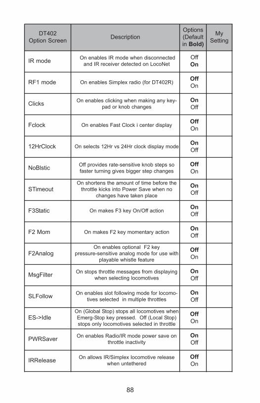
88
DT402
Option ScreenDescription
Options
(Default
in Bold)
My
Setting
IR modeOn enables IR mode when disconnected
and IR receiver detected on LocoNet
Off
On
RF1 mode On enables Simplex radio (for DT402R)Off
On
ClicksOn enables clicking when making any key-
pad or knob changes
On
Off
Fclock On enables Fast Clock i center displayOff
On
12HrClock On selects 12Hr vs 24Hr clock display modeOn
Off
NoBlsticOff provides rate-sensitive knob steps so
faster turning gives bigger step changes
Off
On
STimeoutOn shortens the amount of time before the
throttle kicks into Power Save when no
changes have taken place
On
Off
F3Static On makes F3 key On/Off actionOn
Off
F2 Mom On makes F2 key momentary actionOn
Off
F2AnalogOn enables optional F2 key
pressure-sensitive analog mode for use with
playable whistle feature
Off
On
MsgFilterOn stops throttle messages from displaying
when selecting locomotives
On
Off
SLFollowOn enables slot following mode for locomo-
tives selected in multiple throttles
On
Off
ES->IdleOn (Global Stop) stops all locomotives when
Emerg-Stop key pressed. Off (Local Stop)
stops only locomotives selected in throttle
Off
On
PWRSaverOn enables Radio/IR mode power save on
throttle inactivity
On
Off
IRReleaseOn allows IR/Simplex locomotive release
when untethered
Off
On

89
DT402
Option ScreenDescription
Options
(Default
in Bold)
My
Setting
DplxBadOn enables white flashlight LED to blink
when repeated Duplex radio messages fail.
On
Off
DxRxLPwrOn enables maximum Duplex power saving.
Disables slot follwoing updates.
On
Off
NewTypesOn allows throttle to overide command sta-
tion new- type loco speed step settings
On
Off
Nu Type=
128 speed step setting
14 speed step setting
reserved
28 speed step setting
Advanced 128 speed step setting
reserved
Advanced 28 speed step setting
128
14
tR1
28
128A
RES
28A
Recall#
Recall stack set at last 4 entries
Recall stack set at last 8 entries
Recall stack set at last 16 entries
RC04
RD08
RC16
BackLite
Maximum backlight brighness-highest power
consumption
Maximum backlight brighness-lowest power
usage
2
MAX
1
MIN
RF1 Freq RF1 channel- info onlyA
B
Throt ID Optional unique throttle ID# 427F
XPFnHoldOn allows mutiple expanded function keys
per X1 or X2 choice
On
Off
XP Slots reservedOn
Off
Duplex RFOn enables RF24 to operate in Duplex
mode. Off turns off Duplex choice
On
Off
FactoryDSelect ON and press eNTeR key to force
all options settings to factory defaults
On
Off
90
17.0 Programming Configuration Variables (CVs)The decoders installed in your locomotives provide you with the ability to cre-
ate a more realistic operating experience through the configuration variables
(CVs for short). The DT402 series throttles support configuration of up to
1024 CVs!
It is a good idea to run your decoders with the default CV values that come
pre-programmed in your decoders until you get used to the performance char-
acteristics and how they work on your layout. Once you are comfortable with
running the trains, then you can begin customizing loco characteristics.
Each CV (configuration variable) controls a specific characteristic of the
decoder, which in turn controls how the locomotive performs. See your
decoder manual for a list of the most commonly used CVs and their meanings.
Each decoder comes pre-programmed from the factory with the default settings
outlined in your decoder manual. You can change your decoder’s performance
characteristics by changing the CV values entered in the CVs you want to
change. Each of these CVs can be set up when your command station is in the
programming mode. The CVs are remembered in the decoder until it is repro-
grammed to with a different CV value. Please refer to your Digitrax Mobile
Decoder Manual for a complete listing of the CVs supported by each decoder.
Important Note on Programming:
Programming decoder CVs is most commonly and easily done on an isolated
programming track and the following examples use that method. See
Section 6.1 for details on setting up the programming track.
Simplex Radio and infrared throttles must be plugged into LocoNet to program
CVs on the programming track. Ops Mode Programming can be done without
plugging simplex radio throttles into LocoNet. IR throttles must be plugged in
for Ops Mode Programming. Duplex throttles can program without plugging
in on both the programming track and in Ops mode.
The latest information on Digitrax Decoders is available online for download at
www.digitrax.com in the Manuals and Instructions section.

91
17.1 Programming Mobile Decoder Addresses1. Be sure that only the loco you want to program is on the programming
track (see Section 6.1). If you are using operations mode programming,
the loco you want to program can be anywhere on the layout but it must
have a decoder that is capable of ops mode programming installed.
2. Press the PROG key to enter programming mode. The DT402 will display
the following to show you are in the Program mode:
“CVNo” on the left side indicates that configuration variable numbers will
show on the left and “dAt” on the right side indicates that CV values or data
will show on the right side of the display.
The mode indicator in the center of the bottom line of the display shows
which programming mode the throttle was using the last time it was in pro-
gramming mode. Press the PROG key to cycle through the following
options:
PG = Paged mode (Digitrax Preferred Programming Mode)
PH = Physical register mode
Pd = Direct mode
Po = Operations mode (See your Command Station manual).
3. After a few seconds, the display will display the last CV and CV Value you
programmed. If the display does not show Ad2=???, turn the L Throttle
knob counterclockwise until you see Ad2 in the left side of the display:
4. If you want to program a 4-digit address, press the R Throttle knob once to
change the display to:
You can toggle between 2- and 4-digit address programming by pressing
down on the R Throttle knob.
5. Use the PROG key to select which programming mode you wish to use.
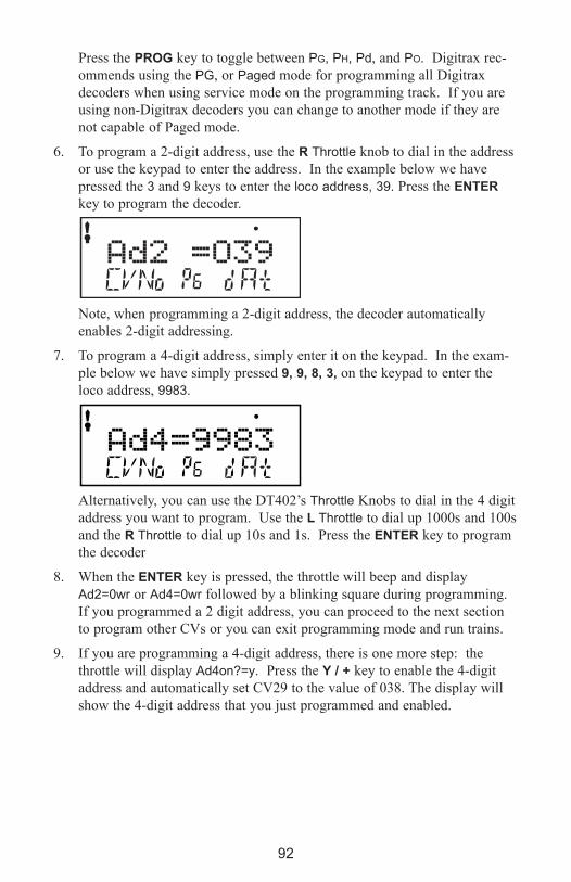
92
Press the PROG key to toggle between PG, PH, Pd, and PO. Digitrax rec-
ommends using the PG, or Paged mode for programming all Digitrax
decoders when using service mode on the programming track. If you are
using non-Digitrax decoders you can change to another mode if they are
not capable of Paged mode.
6. To program a 2-digit address, use the R Throttle knob to dial in the address
or use the keypad to enter the address. In the example below we have
pressed the 3 and 9 keys to enter the loco address, 39. Press the eNTeR
key to program the decoder.
Note, when programming a 2-digit address, the decoder automatically
enables 2-digit addressing.
7. To program a 4-digit address, simply enter it on the keypad. In the exam-
ple below we have simply pressed 9, 9, 8, 3, on the keypad to enter the
loco address, 9983.
Alternatively, you can use the DT402’s Throttle Knobs to dial in the 4 digit
address you want to program. Use the L Throttle to dial up 1000s and 100s
and the R Throttle to dial up 10s and 1s. Press the eNTeR key to program
the decoder
8. When the eNTeR key is pressed, the throttle will beep and display
Ad2=0wr or Ad4=0wr followed by a blinking square during programming.
If you programmed a 2 digit address, you can proceed to the next section
to program other CVs or you can exit programming mode and run trains.
9. If you are programming a 4-digit address, there is one more step: the
throttle will display Ad4on?=y. Press the Y / + key to enable the 4-digit
address and automatically set CV29 to the value of 038. The display will
show the 4-digit address that you just programmed and enabled.

93
10. Press the eXIT key to quit programming mode and return to normal opera-
tions. Or if you want to continue programming additional CVs, see the
next section.
11. If your command station is a DB150 and you are using any method other
than Operation mode for programming, you will need to turn track power
back on after you complete programming. Press the PWR key, then press
the Y / + key, then press the PWR key to exit power mode. The DCS50
and the DCS100 do not require this step.
17.2 Programming CVs Other Than AddressesThere are 1024 different CVs that have been defined to handle many character-
istics you might want to use for your locomotives. Your decoder manual has a
complete listing of CVs that are available in specific decoders, what they do
and suggested values for each CV.
1. Place the decoder equipped locomotive you want to program on the pro-
gramming track. If you are using operations mode programming, the loco
you want to program can be anywhere on the layout but it must have a
decoder that is capable of ops mode programming installed.
2. Enter Program Mode by pressing the PROG key. The display will show
the last CV and CV Value you programmed. In the case below, it is the
last loco address
3. Select the programming mode you wish to use by pressing the PROG key
until the method you want appears in the Mode Indicator. Digitrax recom-
mends using the Pd, or Direct mode for programming Digitrax decoders
when using service mode on the programming track.
4. Turn the L Throttle to begin selection of the CV# you want to program.
You will see the icon displayed on the left of the DT402 display when
you are entering CV Numbers. You can dial up the number using the
L Throttle or you can use the keypad to enter CV#s 01 through 1024.

94
5. Press the R Throttle to activate the CV value. You will see the icon dis-
played on the right of the DT402 display when you are entering CV
Values. Use the R Throttle to dial up or the keypad to enter the CV value
you want. CV values are displayed as decimal numbers (0-255) by default.
Remember that you can press the R Throttle knob to toggle the CV value
display between decimal and hex as shown below.
6. Press the eNTeR key to program the selected CV value into the selected
CV number.
7. Press the eXIT key to quit programming mode and return to normal opera-
tions. You can program as many CVs and their values as you want in a
session. When you are finished, press Press the eXIT key to quit program-
ming mode and return to normal operations.
8. If your command station is a DB150 and you are using any method other
than Operation mode for programming, you will need to turn track power
back on after you complete programming. Press the PWR key, then press
the Y / + key, then press the PWR key to exit power mode. DCS100 does
not require this step.
17.3 Operations Mode ProgrammingOperations mode programming lets you program CVs in decoder equipped
locomotives equipped with Extended Packet Format decoders while they are on
the mainline. A typical use for Ops mode programming would be to change
the acceleration rate (CV03) or the deceleration rate (CV04) of your locomo-
tives to simulate the weight and braking capability of the train to compensate
for changing the number of cars or power units on a train.
Your DT402 can use ops mode programming to change the CV value in ANY
CV, including 2-digit and 4-digit addresses.
Ops mode programming can be performed by any DT402 at any time since the
throttles are not competing for usage of the single programming track.
DT402 throttles must be plugged in for Ops Mode. DT402D and DT402R
throttles can do Ops Mode Programming wirelessly.

95
When you enter programming mode with a DT402R, Ops mode is the only
programming mode that will be available unless you plug in to LocoNet.
How to use Operations Mode Programming
1. Select the loco address that you want to program on either the L or R
Throttle. Be sure that the address you want to program is the active throt-
tle, the one with the blinking smoke when you enter programming mode.
2. Enter Program Mode by pressing the PROG key to enter programming
mode. The display will show the last CV and CV Value you programmed.
3. Press the PROG key until the “Po” appears in the Mode Indicator area of
the display. If you are using an untethered infrared or radio throttle, the
display will automatically show Po. The DT402 display will show the
address that was selected on the active throttle in the right side of the bot-
tom line of the display. This is the address that you are preparing to pro-
gram.
4. Use the L Throttle knob to dial up the CV you want to modify. Use the R
Throttle knob to dial up the CV value you wish to program for the CV.
The example below shows CV04set to a value of 003 for loco address 597.
5. Press the eNTeR key to program the selected CV value into the selected
CV number. You can program as many CVs and their values as you want
in a session.
6. Press the eXIT key to quit programming mode and return to normal opera-
tions.
7. With ops mode programming, the command station does not turn off track
power. If you are using a DB150, you do not need to turn track power
back on after programming with ops mode like you do with service mode
programming.
17.4 Busy or Fail MessageIf you get a “Busy” message in response to any programming task, the system
is temporarily busy and you will have to try the task again until you get a
“Good” response.
If you get a “Fail” message in response to any programming task, check to be
sure that there is a loco on the programming track and that the programming
track is powered.
To end a programming read back that is taking too long, simply press the
BACk key.

96
17.5 Reading Back CV Values ProgrammedDCS100 and DCS50 command stations allow read back of the configuration
variable values programmed into your decoders. Since you must use the pro-
gramming track for this, DT402 and DT402Rs must be plugged into LocoNet
to read back CV and their values. The DT402D can read back while not
plugged in.
Systems with a DB150 command station are not able to read back CV Values
programmed into decoders.
1. Place the decoder-equipped locomotive you want to program on the pro-
gramming track. You can also do an ops mode read back with Digitrax
transponding decoders if you have a LocoNet device that allows ops mode
read back plugged in to LocoNet.
2. Enter Program Mode by pressing the PROG key to enter programming
mode. The display will show the last CV and CV Value you programmed.
3. Select the programming mode you wish to use by pressing the PROG key
until the method you want appears in the Mode Indicator. You can read
back in PG, PH, Pd, or Po modes with the following restrictions:
PG - Paged Mode no restrictions
PH - Physical Register Mode can only read CV01-CV08. You should not
rely on values in the display for CVs above 08 when reading back in
physical register mode.
Pd - Direct Mode no restrictions
Po - Operations Mode read back can only be used with Digitrax decoders
that are capable of ops mode read back when there is a device
attached to LocoNet that supports ops mode read back. Digitrax
transponding decoders and DCS100 would allow ops mode read back.
4. To read back the CV value programmed for the two-digit address, use the
L Throttle knob to dial up Ad02 (CV01) on the left side of the text area and
then press the DISP key. The text area will show Ad2 =rd followed by a
flashing box. When the read back is finished, the CV value (the 2-digit
address) will be displayed on the right side of the text area.
5. To read back the 4-digit address that is programmed into the decoder use
the L Throttle knob to dial up Ad02 on the left side of the text area, then
press the R throttle knob to change to Ad4. The text area of the display
will show Ad4=???? (disregard any value that appears at this time). Press
the DISP key and the display will change to Ad4=8rd followed by the
flashing box. When the read back is finished the 4 digit address will be
displayed on the right side of the text area.

97
6. To read back any other CV start at AD2=??? (Use the L Throttle knob to
dial in Ad2 on the left side of the display or if you were in four digit
addressing, press the R throttle knob once). Use the L Throttle knob to dial
up the CV you want to read back or use the numeric keypad to enter the
CV Number. Press the DISP key the display will show the CV number=rd
followed by the flashing box. When the read back is finished, the CV
value for that CV will be displayed in the Right side of the text area.
Note: You can abort any read back in progress by pressing the BACk key.
7. Once you have read back any CV, you can change its value by dialing in
the CV value you want and pressing the eNTeR key.
8. Press the eXIT key to quit programming mode and return to normal opera-
tions (Fn Mode). You can read back and re-program as many CVs and
their values as you want in a session. When you are finished, press Press
the eXIT key to quit programming mode and return to normal operations.
18.0 How the DCS100 Manages AddressesYour command station has a finite number of “slots” available in its memory.
The factory default is set for 22 addresses. Once the slots available in your
command station are full, the system will display the “slot=max” or “FF” mes-
sage to let you know that you need to release some locos if you want to select
and run others. See Section 9.0 (OpSw 44) for details on changing the default
value and for how many slots the DCS100 command station can handle. The
section also explains how your command station handles purging of addresses
from the system to allow for more addresses to be selected and run.
18.1 Purging of addresses:Purging is the process by which the DCS100 changes the status of decoders
that are either not being used or are unattended to make room for other
addresses to be selected and refreshed by the command station. See Section 9.0
for setting the DCS100 OpSw to purge addresses.

98
19.0 Decoder StatusThe command station assigns status codes to each locomotive address in the
system. Addresses are either selectable or not selectable. Decoders are not
selectable if they are in-use on another throttle or if they are part of a consist.
If you try to select an in-use address, you will be prompted to “Steal” the
address. If you select a decoder that is part of a consist, you will be able to
send function commands but you won’t be able to control its speed or direc-
tion. The text line in the DT402 display will show “top”, “cn” or “mid” if the
address is part of a consist, otherwise it will show “stat”. This display is fol-
lowed by the status code for one of the following modes of operation.
Status editing is used most often when you are running non-Digitrax decoders
that do not have 128 speed step capabilities. If you can’t get a non-Digitrax
decoder to work on your layout and you are sure you are using the correct
address for the decoder, you probably need to status edit it to run in 14 or 28
speed step mode.
19.1 Status editing a Decoder1. Press the LOCO key to enter address selection mode, the display will begin
flashing the address on the active throttle and will display “Sel Loco” in the
text area to prompt you to select an address. Lo will also be flashing.
2. When you use the Throttle knobs or key pad to enter the address of the
locomotive you want to select, the display will show the current status of
the decoder. To display the status code of the loco address that is flashing
in the display when you enter selection mode, just turn the throttle knob up
one address and then back to the original address and the status code will
display on the Display.
Display Meaning
28 28 Speed Step Mode
14 14 Speed Step Mode
128 128 Speed Step Mode - Digitrax Preferred Mode
*28 FX 28 speed step-enable advanced consist mode
x01 Reserved, Do not use
x02 Reserved, Do not use
*128 FX 128 speed step-enable advanced consist mode
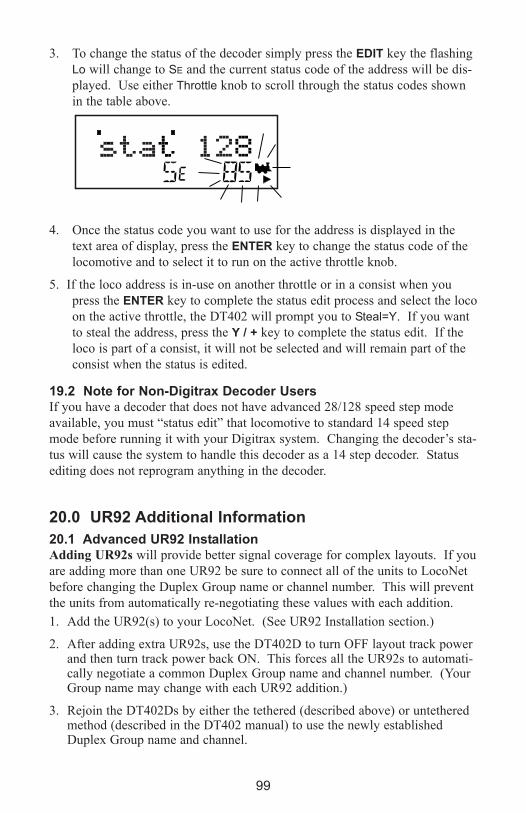
99
3. To change the status of the decoder simply press the eDIT key the flashing
Lo will change to SE and the current status code of the address will be dis-
played. Use either Throttle knob to scroll through the status codes shown
in the table above.
4. Once the status code you want to use for the address is displayed in the
text area of display, press the eNTeR key to change the status code of the
locomotive and to select it to run on the active throttle knob.
5. If the loco address is in-use on another throttle or in a consist when you
press the eNTeR key to complete the status edit process and select the loco
on the active throttle, the DT402 will prompt you to Steal=Y. If you want
to steal the address, press the Y / + key to complete the status edit. If the
loco is part of a consist, it will not be selected and will remain part of the
consist when the status is edited.
19.2 Note for Non-Digitrax Decoder UsersIf you have a decoder that does not have advanced 28/128 speed step mode
available, you must “status edit” that locomotive to standard 14 speed step
mode before running it with your Digitrax system. Changing the decoder’s sta-
tus will cause the system to handle this decoder as a 14 step decoder. Status
editing does not reprogram anything in the decoder.
20.0 UR92 Additional Information
20.1 Advanced UR92 InstallationAdding UR92s will provide better signal coverage for complex layouts. If you
are adding more than one UR92 be sure to connect all of the units to LocoNet
before changing the Duplex Group name or channel number. This will prevent
the units from automatically re-negotiating these values with each addition.
1. Add the UR92(s) to your LocoNet. (See UR92 Installation section.)
2. After adding extra UR92s, use the DT402D to turn OFF layout track powerand then turn track power back ON. This forces all the UR92s to automati-cally negotiate a common Duplex Group name and channel number. (YourGroup name may change with each UR92 addition.)
3. Rejoin the DT402Ds by either the tethered (described above) or untetheredmethod (described in the DT402 manual) to use the newly establishedDuplex Group name and channel.

100
Setting Duplex Group Name: You can use the DT402D to edit the UR92’s
Duplex Group name to one you choose. This change is optional, and the UR92
factory default will work out of the box with no change. You should have all
UR92s connected to the layout before changing the Duplex Group Name or
they will automatically renegotiate and may change the preferred name to a
default.
1. Connect the DT402D to the front RJ12 jack of any UR92 on the LocoNet.
2. On the DT402D press the OPTN key and then the eDIT key.
3. The 8 character Duplex Group name will appear in the display center.
4. Use the R Throttle knob to change the first character value. It will blink asit is changed. When the desired character is seen, use the L Throttle knob tomove across and select a character to modify.
5. Press the eNTeR key to update the current displayed characters as the newUR92 Duplex Group Name. To skip making any changes, simply press theeXIT key.
6. After changing the Duplex Goup Name, your other DT402Ds will need torejoin to use this new Group Name. Note: As long as Duplex Group Nameis unique, it is generally possible to run dozens of different layouts on thesame channel number in close proximity.
Setting the Duplex Group Channel: You can use this capability to move the
duplex channel away from signal interference caused by other devices.
1. Connect the DT402D to the front RJ12 jack of any UR92 on LocoNet.
2. On the DT402D press the OPTN key and then the eDIT key. The Groupchannel number (11-26) will now show in the lower left hand side of thedisplay.
3. Use the Y / + key to change to a higher channel in the available range of 11through 26. The N / - key will change to a lower channel.
4. Press the eNTeR key to update the currently displayed channel as the newUR92 channel to be used with the Duplex Group Name.
5. After changing the channel all DT402Ds will have to rejoin to use this newchannel. To skip making any changes, simply press the eXIT key.
Note: If you suspect a Wireless LAN or other device is causing interferenceand limiting range, you can change the channel as above, and searchthrough all available 16 channels to find one that gives the best coverage.
See additional resources at www.digitrax.com. There are additional utilities tolet you scan the layout environment for any signals using the installedUR92’s as scanners and to easily update your Duplex Group name, channeland to set up a Password to protect your Group from unauthorized access.
20.2 Troubleshooting UR92 InstallationTo get the best performance from your duplex radio installation, walk around

101
the layout and check Duplex operation for adequate signal coverage.
Depending on the layout size, geometry and surrounding materials it is often
possible to move the UR92(s) to better cover dead spots. Experimenting with
UR92 location will usually help you locate a position that is best for your lay-
out. Note that DT402D orientation and body position of you and your opera-
tors may also affect the UR92’s range and reception.
On very large layouts or layouts with problem areas, it is possible to add more
than one UR92. Adding extra units will automatically provide space-diversity
coverage and reliability. Adding multiple UR92s is covered in the Advanced
Installation and Customization section of these instructions.
If duplex range is poor, it may be due to interference from a Wireless LAN or
similar device operating continuously on the same channel. The next section
outlines several ways to avoid interference and congestion from other devices.
20.3 Resetting UR92 To Factory DefaultsYou are unlikely to encounter a problem that will require a factory reset. One
such instance may occur if you set a Password for your Duplex Group Name
and forget what it is. Resetting to factory default condition is an easy way to
correct the situation.
1. Disconnect the UR92(s) from the LocoNet. If you have more than oneUR92 in your layout, you must disconnect all of them to do a full factoryreset on each unit as follows.
2 Disconnect any throttle that is plugged into the UR92.
3. Leave the PS14 power supply connected to the UR92 and to the wall outlet.
4. Press and hold the button (next to the power supply jack) for two seconds oruntil both the red and green LEDs begin to blink. Release the button.
5. When the lights stop blinking, unplug the power supply.
6. Reconnect the PS14 DC power supply to the UR92. The green and redLEDs will blink and then the red LED will stay on.
7. Connect the UR92 to your working LocoNet system using one of the RJ12jacks at the rear of the UR92. The red LED will go off and the GREENRADIO LED will blink at a 2-second interval to indicate that it is set up forduplex radio operation and is working.
8. The UR92 is now set to the factory default Group Name of Dtxnnnn(where “nnnn” is the unit serial number) and Channel 11.
21.0 Troubleshooting Problems
21.1 I’m lost!If your DT402 display isn’t showing you what you expect based on the manual,
press the eXIT key to return to normal operating mode Fn. Then try the throttle
task again.

21.2 Runaway train or layout!• Press the PWR key followed by the N / - key, OR
• Flip the MODE switch to “SLEEP” on the DCS100 Command Station.
Either way, the layout will stop to give you a chance to regain your composure.
To resume operations where you left off
• Press the PWR key followed by the Y / + key, OR
• Flip the MODE switch to “RUN” on the DCS100 Command Station.
21.3 Nothing is respondingIs track power turned on? Is your throttle in Idle or stopped and displaying a
flashing TRACK POWER indicator and Trk=Idle in the throttle display?
Press the PWR key followed by the N / - key then Y / + key then PWR key to
toggle the track power off then on. You should see the TRACK POWER indica-
tor on the DT402 come on solid.
21.4 Can’t select a loco on my throttle
Is the loco in use by another throttle Did the throttle ask you “STEAL=Y?”.
Is the loco part of a consist?Do you see a cn in the display when you try to select it? A loco in a consist
cannot be selected and run separately. You can still control some Functions.
Have you changed the loco address?You can read back the loco address to see if it has been changed. See
Section 17.5.
Does your throttle say “slot=max”? This means that the system’s capacity to handle operating locos is full. The
DCS100 default setting can run up to 22 addresses at the same time. If you
have the “slot=max” message, be sure that all locos that are not running are
released from throttles or set DCS100 OpSw 44 to “c” (closed) to increase the
number of addresses to 120. See Section 9.0 for setting OpSw. A quick way to
free up slots when using the DT402 throttle is to address a loco you’ve been
running and then press the EXIT key. As an example, the key sequence LOCO-
1-1-8-EXIT releases loco address 118 from the system and thereby frees a slot.
21.5 Clean TrackThe majority of intermittent operation problems can be traced to bad connec-
tions and poor or noisy wheel pickups on locomotives. Check track cleanliness
and quality of wheel pickups.
21.6 The Quarter TrickIf your track does not have adequate power supply to the locomotives, then the
signal won’t get through either. Take a quarter or screwdriver blade and go
around your layout creating electrical shorts every 10 feet. Your DCS100
102

should beep 4 times and shutdown when the short is present. When the short is
removed, the booster should beep once within 2-3 seconds and return to normal
operation. If this does not happen, then you need to add more feeders. See
Section 6.3.
21.7 The LT1 TesterCheck your LocoNet cables with the LT1 tester to be sure you don’t have any
cables that were made incorrectly. See Section 5.8.
21.8 Decoder Won’t Respond
Is the loco on powered track?If the TRACK POWER indicator on the DT402 is off or flashing, press PWR
key and the Y / + key to turn on track power.
Use the “Quarter Trick” above to test for track power at several locations
around the loco. If there is not track power, check your layout wiring.
Can you select the loco on your throttle? If not, is the loco in use by another throttle or is it part of a consist (do you see
a cn in the display when you try to select it)? See Section 11.0.
Do the settings in CV29, the configuration register, match the com-
mand station output? If your decoder is a 14-step decoder running on any Digitrax system using fac-
tory defaults, status editing will be needed for that decoder. See Section 19.1.
Have you reset any CVs since the last time you ran the locoIf so, go back and change them to their default CV values and then try to run
the loco. It is possible to set acceleration so high that it will take 10 minutes
for the loco to start moving. To reset to factory default, see the Decoder
Manual for a full listing of CVs.
Was the loco running just before it stopped?If the decoder is very warm it may be in thermal shutdown. Let it cool off and
see if it starts again. Also check for localized track problems. See Quarter
Trick on previous page.
Are there burn marks on the decoder?
You’ll need to send it in for repair!
If all else fails, reprogram the decoder address and reset CVs to
default values.
21.9 “Strange” Locomotive LightsIf you can’t control the operation of the lights in your locomotive with the
DT402 (in default 128, or 28 speed step mode), be sure that the decoder is pro-
grammed in advanced 28 speed step mode.
Do this by programming CV29 with a value of 06. See your Decoder Manual
for more information about programming decoders.
103
104
Glossary128 Speed Step Mode: the motor voltage/speed curve of the decoder equipped
loco from stop to full speed has 128 discrete speed steps. This means that you
have 128 discrete speed steps at your disposal for excellent speed control, espe-
cially at very low speeds. 128 speed step operation will give a significant
improvement in speed control over 14 or 28 step operation.
2-Digit Address: decoder address between 01 and 127 which is expressed as a
2 digit number. Addresses above 99 are expressed as hexadecimal numbers.
The DT402 translates these numbers into three digit numbers 100-127.
Technically a 2 digit address is a 7 bit address and is the baseline packet format
for DCC addresses. It is sometimes called the short address.
4-Digit Address: decoder address between 0128 and 9983. Not all 4 digit
addresses in this range are actually available for use. Your DT402 can access
0128 through 9983. Digitrax handles addresses below 0128 as two digit
addresses to avoid confusion. Technically a 4 digit address is a 14 bit address
and is considered an extended packet format DCC decoder address.
Sometimes this is called the long address.
+: plus or add, used to increase speed or other numbers in DT402 display.
Also used to add loco addresses to consists.
-: minus or remove, used to decrease speed or other numbers in the DT402 dis-
play. Also used to remove loco addresses from consists.
AC or Alternating Current: An expression used to describe an electrical
wave form that cycles or alternates above and below 0 volts. In the U.S.,
household electricity is 60 cycle, alternating 60 times a second, 110-120 volts.
Acceleration: The rate at which the decoder increases from one speed step to
the next in response to a new increase speed command. Use CV03 to set this
value for each decoder. This feature is used to simulate train weight and to
cause your model to respond more prototypically when you increase the throt-
tle.
Active throttle: Digitrax DT throttles are actually two throttles in one. Each
handheld can control two different addresses or consists at a time one on the
right side or R Throttle and the other on the left side or L Throttle. The DTs
display is shared by the two sides of the throttle. The side for which informa-
tion is currently in the display is called the active throttle.
Address, Decoder: an identifying number programmed into a particular mobile
or stationary decoder. The system uses the decoder address to send commands
to the appropriate loco or accessory decoder.

105
Address Range: Analog address range is 00. 2 digit address range is 01-127, 4
digit address range is 0128-9983.
Advanced (EPF) Consisting Method: consist information is stored in each
decoder. Locos can be added to and deleted from the consist in any orienta-
tion. This method requires that all locomotives in the consist be equipped with
decoders that support this feature (EPF decoders). This method lets you set up
a consist that is “transportable” from one layout to another. The problem is
that you must be sure to put the locos back on the track in the same order and
orientation you programmed them for or you can get some unexpected results.
Advanced Mode (28 Speed Step Mode): the motor voltage/speed curve of the
DCC loco from stop to full speed has 28 discrete speed steps. This means that
speed control will be limited to 28 steps. 28 speed step mode gives fine speed
control. Increasing to 128 speed step operation will give a significant improve-
ment in speed control, especially at very slow speeds needed for prototypical
switching operations. Advanced mode is offered in most command stations
because there are decoders on the market that are not capable of 128 step mode
operation.
Analog Loco: A locomotive operating on a DCC layout without a DCC
decoder installed. Also called a Conventional Loco.
Analog Mode Conversion: When a Digitrax decoder does not see DCC pack-
ets on the layout it changes automatically to DC operation. Not all DCC sys-
tems support this feature so you may have to program non-Digitrax decoders to
operate on analog layouts. Automatic analog mode conversion can be disabled
by programming CV29.
Autoreversing: a feature of Digitrax boosters that allows a train to enter and
exit reversing sections automatically without the need for the operator to throw
a switch to match track polarities on either side of the reversing section.
Ballast Lamp: For use as a buffer between DC and DCC track sections, a bal-
last lamp is connected across one of the double gaps separating the two track
sections. For most model railroad applications a 12 volt automobile brake
lamp wired in series is used for this purpose.
Basic Consisting Method: Program all the locomotives in a consist to the
same address and run them on one throttle. In this case all the locos must be
running in the same direction unless you have set up normal direction of travel
as reverse or have rewired the motor on locos that you want to run “back-
wards” in the consist.
Booster: Boosters receive the control signal from the Command Station, ampli-

106
fy it and put it on the track as the power that runs the locos. You can have sev-
eral boosters on a system, each driving its own track section. You can have
both regular or auto reversing boosters depending on your needs. Also called
Power Booster, Power Station.
Browsing: scanning sequentially through locomotive or accessory decoder
addresses and statuses in you throttle. Browsing is done with the DT402 by
turning the throttle knobs or using the Y+ or N- Keys.
c: closed, indicates that the turnout is in the straight through position, set for
the mainline. For op switch set ups, consult your manual for the meaning of
c and t.
Cab: See Throttle.
Command Station: Most systems have one Command Station that generates
the commands that are sent to the decoders. The command station also pro-
duces Rail Sync so that all the devices on your LocoNet work together.
Common (Loco Status): a locomotive that is not currently “in-use” by a throt-
tle connected to LocoNet but is still being refreshed by the command station.
A loco with a status of “common” is selectable by any throttle on LocoNet.
Common Rail Wiring: A wiring system in which one side of all the track
power supplies are connected. The common rail concept simplified block
wiring in conventional DC systems, but is not recommended for DCC wiring.
(see Direct Home Wiring).
Compatibility: the ability of equipment made by various companies to operate
together on the same layout. DCC compatibility extends to decoders and
boosters but not to throttles, command stations, system architecture and
advanced features that are not DCC related.
Complete Train Control: the integration of many technologies including DCC
for total layout control. Since DCC covers only limited aspects of layout
control, the hybrid Digitrax Complete Train Control goes beyond the basics of
DCC to provide you with a total layout control system.
Configuration Register (CV29): this special CV controls several different
decoder characteristics including:
1. Whether the decoder uses standard 14 speed step mode or advanced
28/128 speed step mode
2. Whether or not the decoder will automatically convert to DC operation
when no DCC signal is present.
3. In the case of Digitrax FX decoders, the normal direction of locomo-

107
tive travel
4. Whether the decoder uses loadable speed tables and
5. Whether the decoder uses the 2 digit address or the 4 digit address.
Configuration Variables (CVs): these are special storage locations or
“pigeonholes” in your decoders. By programming values into various CVs,
you can control each decoder’s performance characteristics. CVs store infor-
mation like the decoder’s address, start voltage, mid-point voltage, loadable
speed tables and many more. Once you have programmed these characteris-
tics, the decoders “remember” them until you change them again. The NMRA
Standard and RPs define the usage of many CVs while others are defined by
manufacturers.
Conformance Seal: issued by the NMRA after a product has passed the tests
established and administered by NMRA volunteers to “prove” that a particular
product follows exactly to the letter the Standards and RPs set up by the
NMRA that pertain to that product. Conformance seals do not insure interoper-
ability or the quality of the products, only manufacturers provide warranties on
the equipment they sell.
Consisting: linking more than one locomotive together to be controlled by a
single throttle and or address. Also called multiple unit operation, MU’ing,
multiple unit lash ups, etc.
Constant Brightness Lighting: because DCC runs with constant track voltage,
locomotive lights stay on even when the loco is not moving, just like the proto-
type.
Conventional Loco: A locomotive operating on a DCC layout without a DCC
decoder installed. Also called an Analog Loco.
DCC: Digital Command Control.
DC or Direct Current: An expression used to describe an electrical wave form
in which the voltage remains more or less at a value above or below 0 volts.
DC is used by most model railroad locomotives. Sometimes referred to as
Analog.
Deceleration: The rate at which the decoder decreases from one speed step to
the next in response to a new decrease speed command. Use CV04 to program
the deceleration value for each decoder. This feature is used to simulate train
momentum so that, just like the prototype, your model won’t stop immediately
when the brakes are applied.
Decoders, Mobile: the electronic device installed in each locomotive that

108
receives the signal from the command station through the track, decodes it and
tells the loco what to do. Mobile decoders can also include function control,
speed stabilization (back emf), transponding and other features.
Decoders, Stationary (Accessory or turnout): the electronic device for the
turnouts or other accessories that receives the signal from the command station
through the track, decodes it and tells the turnout/accessory what to do.
Decoder Status: the Digitrax command station assigns each decoder a status
based on whether it is new to the system, in-use on a throttle, common in the
system and available for selection or idle. The decoder status determines how
the system treats that address.
Direct Home Wiring: A wiring system in which the DCC booster powers each
rail through an individual conductor or wire. Each booster is wired to its own
power district and there is no common connection between boosters. Digitrax
strongly recommends direct home wiring.
Direct Programming: A type of service mode programming.
Directional Lighting: loco lights can be set up to automatically change so that
the forward lamp is lit when the loco is moving forward and the reverse lamp
is lit when moving in reverse.
Dispatching: use your DT throttle to set up a loco or consist you want to be
run by another operator and then using a couple of keystrokes, dispatch the
loco from the DT throttle and acquire it on the other throttle.
Duplex Transceiver. two way radio operation allows a duplex equipped throt-
tle to send and receive information to the command station via a radio
transceiver while not plugged in to the LocoNet.
EPF or Extended Packet Format: an extension of the baseline DCC format
that allows us to use four digit addressing and other expanded decoder features.
Fn: Shorthand for Function
F0: Shorthand for Function 0. F0 is two functions in one. F0 Forward con-
trols the white function lead and F0 Reverse controls the yellow function lead.
Digitrax ships all decoders set up for automatically reversing head/tail lights
using F0 Fwd and F0 Rev. These can be programmed to operate separately and
be controlled by the operator if you do not want automatic operation.
F1: F1 is usually used to operate the bell if sound is being used.
F2: F2 is a special key set up to act as a momentary function key. When you

press F2 the function will remain active for as long as you hold the key down.
This momentary feature is important if you are using a whistle or horn. F2 can
also be latched on if you are not using it for a horn.
F3-F28: these are regular on/off function keys. F3 and F4 can be turned on
and off by pressing them after the FN F0 Key is pressed and you are in func-
tion mode. F7 and F8 can be accessed by pressing and holding the FN F0 Key
(use this key as a “shift” key) and then pressing the F3/F7 or F4/F8 Key.
Fast clock: used by many operators during operating sessions to simulate pro-
totypical operations. Traditionally, the fast clock is on the wall and is set up to
run at a faster than normal time so that you can “get in a full day’s work on the
railroad in a fraction of the time.”
Functions, Decoder: function leads are extra decoder wires that you can con-
nect to any device on the loco that you want to control from the hand held or
other input device such as a computer. These can be used for locomotive light-
ing, sound units, smoke units, and other locomotive animation tasks.
FX Functions: specially designed functions (available on Digitrax FX and
FX3 series decoders) that let you set up lights on your loco to simulate Mars
lights, Gyra lights, ditch lights, rotating beacons, single or double pulse strobes,
flashing lights, random firebox flicker and more. CVs 49-63 are used to set up
these special light effects.
Idle (Loco Status): a locomotive that has been addressed by the system previ-
ously, is currently selectable by a throttle on LocoNet, and is not being
refreshed.
In-Use (Loco Status): a locomotive that is currently selected on a throttle con-
nected to LocoNet. An in-use loco is having its data refreshed by the com-
mand station and is not selectable by other throttles on LocoNet. The excep-
tion to this is if a throttle “steals” an in-use loco
L: Left throttle, Left reverse key, Left side of DT402 display
Loadable Speed Table: use CV65 through CV95 to enter a value for each dis-
crete speed step in a 28 speed step curve. This feature allows you to customize a
loco’s performance curve and makes speed matching of locomotives possible.
With this feature you can limit the top speed of a loco. Once you have pro-
grammed CV65 through CV95 to set up the table, you will also need to set up
CV29 to enable it. This allows you to enable and disable the table at will and to
keep the table stored even when it is not in use. Digitrax FX and 4th generation
decoders go one step further and give you 128 speed step resolution with load-
able speed tables.
109
110
LocoNet: Digitrax’s powerful communications network especially designed for
model railroad operation.
LocoNet ID:
Mid-Point Voltage: the value programmed into CV06 specifies the voltage to
apply to the motor at speed step 15 in a 28/128 step system and step 7 in a 14
speed step system. This allows you to make a quick adjustment to the motor
voltage/speed curve without setting up a loadable speed table.
MU: Multiple unit operations. See Consisting.
N: No, use the N / - key to respond to DT400/DT402 series throttle text mes-
sages.
New (Loco Status): a locomotive that has not been addressed by the system.
A new loco is selectable by throttles on LocoNet and is not refreshed.
Operating Mode: 14 or 28/128 speed steps. See also, Speed Steps, Standard
Mode, Advanced Mode and 128 Speed Step Mode.
Operations (OPS) Mode Programming: lets you program CVs in DCC locos
equipped with EPF decoders while they are on the mainline. A typical use for
ops mode programming would be to change the acceleration rate (CV03) or the
deceleration rate (CV04) of your locos to simulate the weight and braking char-
acteristics of the train to compensate for changing the number of cars and
power units in the train.
Paged Programming: Digitrax preferred method of service mode program-
ming.
Physical Register Programming: A primitive type of service mode program-
ming. This method is limited to programming 2 digit address, acceleration,
deceleration and start voltage.
Power Booster: See Booster
Power District and Power Sub-district: A power district is the power wiring,
components and equipment attached to that wiring, driven by a single properly
isolated booster. A power sub-district is a sub-division of a power district.
Power Station: See Booster
Power Supply: a transformer that provides power to the layout control system.
Programming: entering values into configuration variables (CVs) available in
DCC decoders or option settings for the throttle or command stations.

111
Programming Track:
Purging: the process by which Digitrax command stations automatically
release locomotives from “in-use” to “common” when they are not selected on
a throttle connected to LocoNet. This makes locos that have been “forgotten”
by their operators available to be selected by other operators to prevent prob-
lems during an operating session.
PWM: Pulse Width Modulation.
R: Right throttle, Right reverse key, Right side of DT402 display.
Recall stack: Digitrax
Release:
Refreshed (Data): Digitrax command stations re-send data to decoders many
times to be sure that the signal is not lost and that you have reliable operation.
All in-use and common locos in the system will continue to be refreshed until
they become idle.
Route: a group of turnouts and their specified positions that will be triggered
by the activation of a single “TOP” switch address to a specified position.
Scaleable Speed Stabilization (back EMF): a decoder that uses back EMF to
maintain constant speed but can also buffer the speed changes to allow for opti-
mal operation. A speed stabilized decoder that is not scaleable will cause a
locomotive to maintain the speed you set no matter what grade the loco
encounters. It’s like “cruise control for your loco.” If speed stabilization is not
scaleable, you can have the pushy pusher problem if you run consists.
Select: To assign a decoder address to a throttle in the system so that the
address can be controlled by that throttle.
Selectable: a DCC decoder is selectable when it is not currently in-use on
another throttle.
Service Mode Programming: service mode programming information sent by
the command station or programmer as a broadcast signal that goes out to all
decoders on the track.
Slot Following: when more than one DT throttle has a single loco address
selected, both DT throttles will have control of that address and both throttle
displays will be updated with the same information. In other words, both oper-
ators will see what the other is doing.

112
Speed Steps: because DCC is a digital system, locomotive speeds are defined
as discrete speed steps. This means that as motor voltage is increased, the
speed of the locomotive increases in a straight line from stop to full speed with
discrete speed values at each voltage.
Split field Motor: Another term for AC motor
Standard Mode (14 Speed Step Mode): the motor voltage/speed curve of the
DCC loco from stop to full speed has 14 discrete speed steps. This means that
speed control will be limited to just 14 steps. 14 speed step mode gives reason-
ably good speed control. Increasing to 28 speed step operation will give much
better speed control and going to 128 speed step operation will give really
excellent speed control. Standard mode is offered in many command stations
because there are some decoders on the market that are not capable of 28 or
128 step mode.
Start Voltage (V-start): the voltage added to the motor drive voltage at the
first speed step. This adjustment allows you to trim the loco to compensate for
its motor efficiency.
Status Editing Decoders: a DCC decoder’s status can be manually changed by
a Digitrax command station at any time the decoder is selectable.
Stealing a Loco: overriding the in-use interlock and forcing the throttle to
select an in-use loco. This can result in having two throttles logged on to and
controlling one address. See also Slot Following.
t: thrown indicates that the turnout is set for the diverging route. For op
switch set ups, consult your manual for the meaning of c and t.
Throttles: Throttles are input devices that tell the Command Station what you
want the decoders to do. You can have many throttles on your system. The
number is determined by the capabilities of the Command Station you are
using. You can also use a computer to create “soft” throttles. Sometimes throt-
tles are also called “Cabs.”
TOP Locomotive: Digitrax calls the locomotive that other locomotives are
consisted to, the TOP locomotive because it is not necessarily the lead loco in
the consist. The TOP locomotive address controls the speed and direction of
all locomotives consisted to it.

113
Transponding: The use of transponders installed in rolling stock and transpon-
der detectors installed in the layout to allow the system to determine the loca-
tion of a particular piece of rolling stock on the layout. Other information
about the rolling stock such as speed, direction, etc. can also be determined.
Transponding is useful for automation of staging yards, dispatching and for
realistic sound systems.
Universal Consisting: the command station handles all consist information
and lets you consist locos with any DCC decoder as well as analog locos. The
locos can be added to and deleted from the consist in any orientation head to
head or tail to tail.
Y: Yes use the Y / + key to answer questions in the DT402 text message dis-
play.
Zero-Stretching: incorporates a time period between packets to give you an
effective DC offset between the two rails. This allows you to control a DC
locomotive along with the DCC locomotives on a DCC system.

114
FCC InformationRadio or TV Interference: (this information is MANDATED by the FCC) This
equipment has been tested and found to comply with the limits for a Class B
digital device, pursuant to part 15 of the FCC rules. These limits are designed
to provide reasonable protection against harmful interference in a residential
environment. This equipment generates, uses and can radiate radio frequency
energy and, if not installed and used in accordance with the instruction manual,
may cause harmful interference to radio communications. However, there is no
guarantee that interference will not occur in a particular installation. If this
equipment does cause harmful interference to radio or television reception,
which can be determined by turning the equipment off and on, the user is
encouraged to try to correct the interference by one or more of the following
measure
• Reorient or relocate the receiving antenna.
• Increase the separation between the equipment and the receiver.
• Connect the equipment into an outlet on a circuit different form
that to which the receiver is connected.
• Consult the dealer or an experienced radio/TV technician for help.
Note that any modifications to the equipment not expressly approved by
Digitrax voids the user’s authority to operate under and be in compliance with
CFR 47 rules, as administered by the Federal Communication Commission.
Digitrax believes any conscientiously installed equipment following guidelines
in this manual would be unlikely to experience RFI problems.
The DT402R is certified for “unlicensed” operations within the United States
by the US FCC and has the identifier as displayed on the unit case. Canadian
ID for DT402R is displayed on the unit case. See unit case for certification
identifiers from other countries.
Important Note: The DT402R is certified by the FCC and by Industry Canada
using a 12” LocoNet cable only. Any modification to the cable may void the
certification. For convenience an extension cord may be attached with a 6 pin
adapter for tethered use only.
For Canadian Users:“This digital apparatus does not exceed the Class B limits for Radio noise
emission from digital apparatus set out in the Radio Interference Regulation or
the Canadian Department of Communications.”
Le present appariel numerique n emet pas de bruits radio-electriques depassant
les limites applicables aux appareils numeriques de la classe B prescrites dans
le Reglement sur le brouillage radioelectrique edicte par le ministere des
Communications du Canada.
FCC Information for RF24 module
FCC ID LV3RF24
IC 3015A-RF24
Warranty and Repair Information
Digitrax gives a one-year “no worries” warranty against manufacturing defects
and accidental customer damage on all Digitrax products. That’s it! Simple,
straightforward warranty, no tricky language!
All warranties on Digitrax products are limited to repair or replacement of
Digitrax products at the discretion of Digitrax. Except to the extent expressly
stated, there are no warranties, express or implied, including but not limited to
any warranties of merchantability or fitness for a particular purpose.
For items that are no longer covered under warranty, whenever possible we will
make repairs to units at fair and reasonable rates.
Please visit our warranty and repair page at www.digitrax.com/warranty for
warranty and repair information and procedures.
Digitrax, Inc. reserves the right to make changes in design and specifications,
and/or to make additions or improvements in its products without imposing any
obligations upon itself to install these changes, additions or improvements on
products previously manufactured.
Digitrax, Inc. is not responsible for unintentional
errors or omissions in this document.
115

116
2-digit address 53, 94, 98, 104
4-digit address 53, 93, 94, 98, 104
Aacceleration 96, 103, 104
address 00 16
analog locomotive 8, 16, 27
AR1 33
automatic reversing 22, 32, 33
BBACK Key 87, 97
ballistic tracking 49, 71
Bar Graph 53, 82
battery DCS100 40, 43
Battery Installation-DT402 11
Battery Replacement-DCS100 41
battery-DT402 49, 70, 72, 76, 89
beeps 15, 38, 40, 41
Bell / 1 key 58
blinking smoke 14, 18, 50, 54, 97
Busy or Fail Message 97
Cchange a LocoNet ID 74
Clean Track 102
CLOC / c 43, 44, 71, 82, 83, 87
closed 82, 106
Common 106
Common (Loco Status) 106, 111
Common Rail Wiring 27, 28, 106
CONFIG 31
Configuration Variables (CVs) 28,
92, 107, 110
Consist 71, 79, 81
Control Panel - DCS100/200 35
Control Panel - DT402 49
Coupler / 3 key 58
DDB150 Booster 30
DCC address 104
DCS100 Audible Sounds 40
Deceleration 107, 110
Decoder Address 27, 28, 53, 111
Decoder Status 52, 100, 108
Decoder Won’t Respond 103
Direct Home Wiring 28, 106, 108
Direct mode 93, 95, 98
Direction 8, 14, 16, 18, 49, 79, 107,
112
Direction Indicator 14, 16, 18, 50,
79
DISP key 98
Dispatch 19, 80, 108
Display - DT402116 14, 50
DT402 SeriesThrottle Controls At
A Glance 14
double click 16
DT402 13, 14
Duplex Radio 9, 10, 70, 76, 91
duplex radio transceiver 25
Eevent driven network 21
FFast clock 76, 83, 109
FCC Information 114
feeder wires 29
FIND Key 88
Function 14, 54, 108, 109
Function Mode 14
GGlossary 104
GROUND 29, 31
HHorn / 2 key 58
IInfrared 70, 72
KKeypad and Knob Clicks 90
INDeX
117
LLAMP / 0 key 58
Layout Wiring 34, 103
LCD 50
Liquid Crystal Display 50
local area network 21
Loco Icon 50
LocoNet 1, 21, 110
LocoNet Cables 24
LocoNet Connection Jacks 25
LocoNet ID 74, 110
LocoNet Wiring 24
Mmechanical detent (DT402) 49
mechanical problems 34
Mode Indicator 51
MU 110
multiple unit 107, 110
NNested Consisting 81
Network Speed 22
No tetherless release allowed 70
non-Digitrax decoder 94, 100, 101,
105
Numeric Keypad 58
OOFF LINE Indicator 38
Operations Mode 27, 70, 93, 95,
96, 97, 98
Ops mode programming 27, 93, 95,
96, 110
OPT / t key 89
option settings 34, 43, 70, 89, 110
Option Switch 43, 82
Option Switch Tables 44
PPaged 93, 94, 98, 110
Peer to Peer 21
Physical Register 93, 98, 110
PM42 33
polled buses 21
power districts 27, 29, 30, 33, 38,
110
POWER IN 8
Power Sub-district 110
PROG A 28
PROG B 28
Programming 92, 93, 95, 110
Programming CVs Other Than
Addresses 95
Programming Mobile Decoder
Addresses 93
Programming Track 27, 28, 92, 93,
95, 98, 111
Purging 45, 99, 111
QQuarter Trick 102, 103
RReading Back CV Values 98
recall stack 49, 91, 111
release 70, 80, 99, 111
Resuming your session 19
Reverse Key
reversing section 28, 31, 105
Route 85, 86, 111
RUN 19
Safety Selection 70
SEL Message 17
Select Address 16, 17
Semaphores 54
Sservice mode programming 28, 71,
108, 110, 111
short circuit alarm 15
Shut Down 19
Slot Following 111
slot=max 99, 102
Smoke Icon 50
speed control 14, 104, 105, 112
Status Edit 100, 112
Stealing 112
Stop the Fast Clock 84
straight line tracking 49
118
Strange” Locomotive Lights 103
Sw (Switch) mode 43, 82, 85
switch decoder address 82
System Architecture 21
Tt 43, 112
Testing LocoNet Cables 24
tetherless release 70
Tetherless release allowed 70
Text Area 52
Throttle 14, 49
throttle ID 91
Throttle Jacks 25
Throttle Knobs 49
thrown 82, 112
Track power 15
track power indicator 15, 54
TRACK STATUS Indicator 15, 37
Track Wiring 29
Transformer 110
Transponding 88, 113
Troubleshooting 34, 38, 101
UUP5 Universal Panel 25, 26
UR90 Infrared Receiver 26, 70, 72,
74
UR91 Radio Receiver 25, 26, 70,
72, 74, 75
UR92 Duplex Radio Receiver 9,
25, 26, 70, 72, 99
WWarranty and Repair 115
wire sizes 29