Complete Data Protection for FlashStack with Cohesity ... · FlashStack with Cohesity: Reference...
58
Complete Data Protection for FlashStack with Cohesity: Reference Architecture
Transcript of Complete Data Protection for FlashStack with Cohesity ... · FlashStack with Cohesity: Reference...

Complete Data Protection for FlashStack with Cohesity: Reference Architecture

©2017 Cohesity, All Rights Reserved 2
Table of Contents
Executive Summary...........................................................................................................................................3
Audience...............................................................................................................................................................3
Modern Data Center Challenges..................................................................................................................4
What is FlashStack?..........................................................................................................................................4
Topology................................................................................................................................................................5
System Requirements.................................................................................................................................. ....6
Cisco Unified Computing System Overview............................................................................................8
Cohesity Overview.............................................................................................................................................11
Pure Storage Overview.....................................................................................................................................12
VMware vCenter and Horizon 7 Test Environment Overview and Setup......................................14
FlashStack with Cohesity Integration Setup............................................................................................20
Pure Storage FlashArray//m Integration, Protection and Recovery..............................................22
VMware vCenter and Horizon Integration, Protection and Recovery............................................29
Physical Server Integration, Backup and Recovery...............................................................................38
Microsoft SQL Integration, Protection and Recovery in VMware Environments.......................47
Conclusions..........................................................................................................................................................57
©2017 Cohesity, All Rights Reserved 3
Executive summaryBusiness agility is the critical need and ask of enterprises today. To provide this agility, enterprise IT needs to continually adopt next-generation products and architectures while also reducing spend and doing more with less infrastructure. Optimizing and providing elastic resources at every level are the key imperatives towards allowing businesses to modernize and to achieve IT nirvana. Optimization comes from being able to flexibly provide applications and their underlying compute, network, and storage requirements with a performant and robust infrastructure backbone. But it also comes from understanding which applications need agility vs which applications are fairly static and consequently have quite different IT design considerations. We will discuss the design principles of building a next-generation, “holistic and cohesive” data center compute, network, and storage solution that combines the simplicity, resilience, and performance of next-generation flash storage from Pure Storage® with compute and networking from Cisco® and secondary storage from Cohesity®. This document specifically provides insight on application-centric, pre-validated architectures that deliver high performance. Its focus is to ensure that the recommended architectures can be deployed quickly and scaled seamlessly. We believe that this in turn provides maximum agility while also reducing IT capex and opex, because bottom line costs are more often than not the most important factor in industry. The three primary goals of this design guide are:
1. We will showcase and certify that Cohesity and Pure Storage deliver an optimal blend of performance, user-friendliness, non-disruptive operations, and data recoverability from the micro to the macro for multiple workloads.
2. We will describe a Pure FlashStack™ solution reference architecture that illustrates how these primary and
secondary storage solutions, along with Cisco UCS® and Nexus®, fit together to provide an optimal Converged Infrastructure (CI) for a VMware® Horizon solution that includes the ability to rapidly recover the entire environment – all the way down to individual user files and everything in between.
3. Finally, we will showcase how this unique FlashStack CI solution brings the best of both primary and secondary
storage, hence delivering value to applications in tier 0 through tier 4 workloads.
In summary, we discuss all aspects of running high-performance VMware and physical workloads while focusing on protecting these workloads at every level in the solution stack. Incumbent CI solutions tend to focus on the performance of tier 0-1 workloads while looking at tier 2-4 data protection and data management workloads as an afterthought. However, we strongly believe that integrating data protection at the ground level is the key to a successful deployment. This paper will go deep into the proposed architecture to support the claim. The Flashstack solution combined with Cohesity is built to be optimized at each of these tiers and hence delivers the ultimate value to the end customer by simplifying adoption of CI with a well thought-out design for all workloads running in the modern data center. While this document’s primary test case will focus on a VMware Horizon persistent VDI environment, it is important to note that the use cases shown here are extensible throughout the data center to databases, VSI, physical host workloads and beyond.
Audience The target audience for this document includes storage and virtualization administrators, consulting data center architects, field engineers, and desktop specialists who want to implement a next-generation data center. A working knowledge of VMware vSphere, VMware Horizon, Login VSI, server, storage, backups, networks, and data center design is assumed but is not a prerequisite to read and understand this document.

©2017 Cohesity, All Rights Reserved 4
Modern Data Center Challenges The over-abundance of vendors providing a point solution for a point problem has created a very fragmented and complex siloed data center environment that’s become a nightmare to manage and secure. Just because there are many storage solutions to choose from doesn’t make life simpler for enterprise IT architects. In fact, it has become even more difficult, if not impossible, to pick and construct the simplest and most cost-effective solution. A ‘single’ solution jerry-rigged together with point solutions to solve the compute / storage / network / data protection requirements of all the workloads running in the data center today simply doesn’t pass muster anymore. This complexity is one of the main motivations for enterprises to consider moving their applications to the cloud. Cloud offers the prospect of seamless integration and scale and supposedly takes away the headache of managing siloed infrastructure IT. However, major downsides of this approach are that the cloud can be extraordinarily expensive to operate at scale and the performance of the most important applications can be inconsistent. There is a strong need for an overall solution that is optimized to work out-of-the box with different component parts, delivers simplicity in management by consolidating multiple workloads, and leverages the best aspects of the cloud. Just as virtualization solved the hardware sprawl problem, and hyper-convergence helped resolve the complexities of scale by converging virtualization, compute, network, and storage, and the next big challenges to address are silos and fragmentation.
What is FlashStack? FlashStack CI (Converged Infrastructure) is a flexible, all-flash converged infrastructure solution that brings the flash revolution to your data center, faster. It combines the latest in compute, network, storage hardware, and virtualization software into a single, integrated architecture that speeds time to deployment, lowers overall IT costs, and reduces deployment risk. Highly efficient components coupled with simple, intelligent software reduce the costs associated with power, cooling, and data center space. Based on 100 percent flash storage, FlashStack CI provides the performance and reliability that business-critical applications demand.
The hardware foundation of FlashStack CI includes Pure Storage FlashArray//M, Cisco UCS Blade Servers, Cisco Nexus ethernet switches and Cisco MDS fibre channel switches. VMware vSphere provides the virtualization technology and Cohesity provides the secondary storage layer for data protection and recovery.
FlashStack CI is available from qualified FlashStack Partners who help to provide an excellent converged infrastructure ownership experience. FlashStack Partners have the knowledge and experience necessary to help streamline the sizing, procurement, and delivery of your entire system while simply, easily, and non-disruptively growing with your organization as needs change. A single point of contact for support issues for all components of the FlashStack solution ensures a rapid response to any issues in the stack - and often preemptively, before an issue arises.
Both hardware and software components are combined into a single integrated unit that helps facilitate faster deployments and lowers overall IT costs. Repeatable, turnkey designs for the most common workloads means that your users are online faster and data center administrators are focused on more important automation tasks up the stack.

©2017 Cohesity, All Rights Reserved 5
Figure 1 : FlashStack integrated with Cohesity Data Protection and Data Management Platform The above topology diagram shows the recommended connectivity and components used in this whitepaper. Pure Storage supports mixed Fibre-Channel and iSCSI connectivity, which has the benefit of segregating backup traffic from production workload traffic, thereby enhancing environment resiliency, isolating network traffic and minimizing Recovery Time Objective (RTO) with Cohesity. FlashStack CI has no single point of failure and maintains 100% performance through component failure allowing customers to non-disruptively upgrade and/or add hardware to the solution stack transparently to users.
Today, Cohesity supports iSCSI connectivity, which has been denoted in the above topology diagram. Multiple connections to redundant Nexus switches ensure both throughput as well as protection from any single path or component failure. Worth noting is that mixed FC and iSCSI connectivity with Pure Storage is not a requirement for this design; however, it is recommended as it segregates backup traffic from production traffic, further improving the resilience of the design. For Pure Storage, using only iSCSI or Fibre Channel connectivity is fully supported and performant as well.
Figure 2 : Pure Storage target port configuration
The port connections shown here from the Pure Storage GUI show the mixed FC and iSCSI connectivity used in this design.
©2017 Cohesity, All Rights Reserved 6
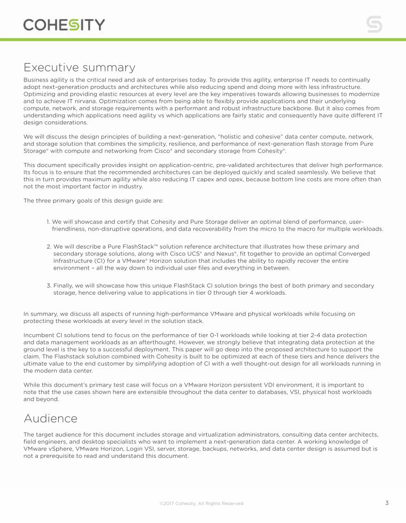
The diagram below provides a simplified view of the flow of data through the FlashStack and Cohesity architecture (redundant Cisco components and exact connectivity are not shown). Important to note is that there are multiple, separate data paths available within the setup that will keep your users online and their data secure and easily recoverable.
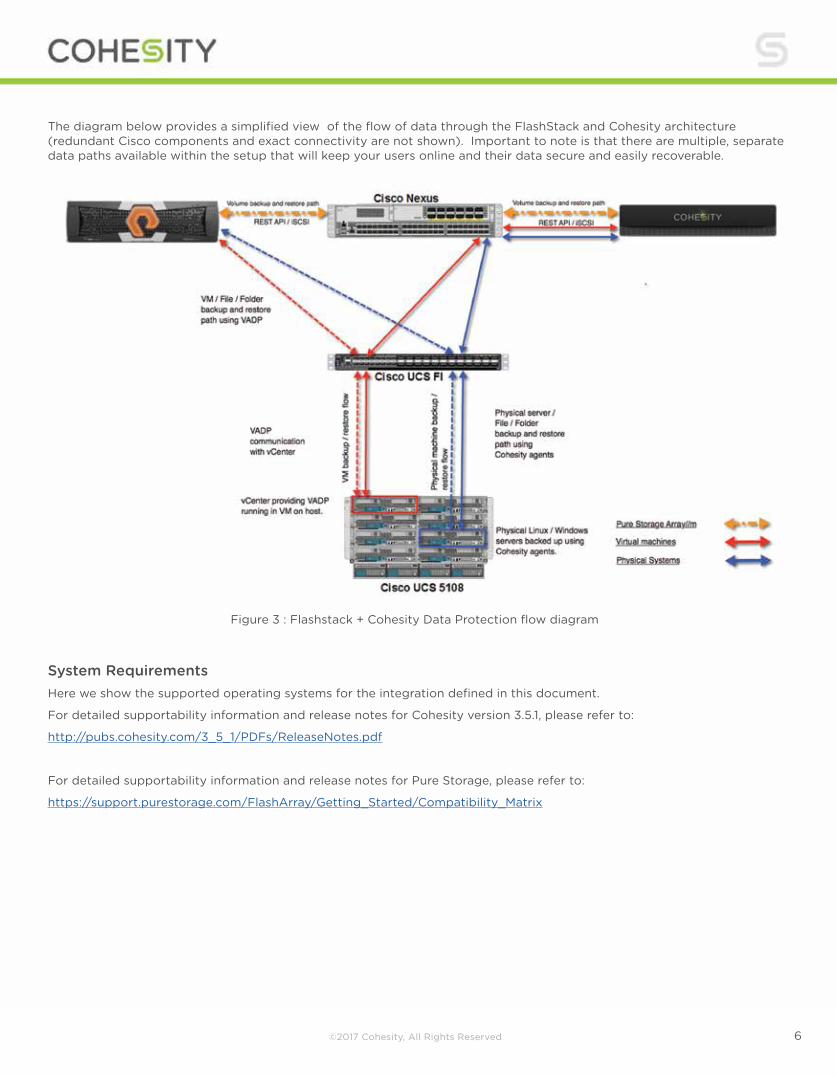
System RequirementsHere we show the supported operating systems for the integration defined in this document.
For detailed supportability information and release notes for Cohesity version 3.5.1, please refer to:
http://pubs.cohesity.com/3_5_1/PDFs/ReleaseNotes.pdf
For detailed supportability information and release notes for Pure Storage, please refer to:
https://support.purestorage.com/FlashArray/Getting_Started/Compatibility_Matrix
Figure 3 : Flashstack + Cohesity Data Protection flow diagram
©2017 Cohesity, All Rights Reserved 7
VMware vSphere Support
The Cohesity and Pure Storage Cluster supports the following versions of VMware vSphere:
6.0
5.x VMware Guest Operating System Support
The Cohesity and Pure Storage Cluster supports the following guest operating systems:
Windows® 2012, 2012 R2, 2008, 2008 R2, 7, 8, 10
CentOS® 6.6+, 7.0, 7.1
RHEL® 6.6+, 7.0, 7.1
Ubuntu® 14.x Windows Physical Server Support
The Cohesity and Pure Storage Cluster supports Physical Servers running the following Windows versions:
Windows 2012, 2012 R2, Windows 2008 R2 Linux Physical Server Support
The Cohesity and Pure Storage Cluster supports Physical Servers running the following Linux® versions:
CentOS 6.7+, 7.0, 7.1
RHEL 6.7+, 7.0, 7.1
Ubuntu 14.x Microsoft® SQL Server Support
The following MS SQL Server versions running in a VMware environment are supported:
Microsoft SQL Server 2014 64-bit running on Windows 64-bit
Microsoft SQL Server 2012 64-bit running on Windows 64-bit
Microsoft SQL Server 32-bit is not supported Microsoft SQL Server Support
Microsoft SQL Server running on Physical Servers is not currently supported; MS SQL Server running in a VMware environment only is supported. Cohesity System and Network RequirementsVerify the following Cohesity Cluster network requirements for a four Node Cohesity Cluster • Reserve eight IP Addresses (four Node IP Addresses and four VIP Addresses) on a single subnet, the Cluster
Subnet
• Verify that the Cluster Subnet can communicate with the vCenter Server Subnet
• Reserve four 10GbE ports on one switch (recommended for best performance)
• Reserve four 10GbE ports on another switch (recommended for best performance)
• Reserve four IP Addresses for IPMI Interfaces. They can be in the IPMI Subnet or the Cluster Subnet.
• Reserve four 1GbE ports for the IPMI Interfaces on a switch
• Enable multicast traffic on your network (required for Cohesity’s auto-discovery function)
Pure Storage Purity Operating Environment Support
This integration requires Purity 4.7.6 and above
©2017 Cohesity, All Rights Reserved 8
Pure System and Network Requirements A Pure Storage Sales Engineer or certified partner will handle the initial setup of the Pure Storage array. Array setup is usually completed in under an hour, without the need for professional services, and only requires six cables in total for the smaller arrays. The base unit with controllers requires 3 rack units (RU), and external capacity shelves are 2 RU each. External shelves are redundantly wired to the base controller unit with 12GB SAS cables. Pure Storage FlashArray//M is a block storage device and supports both Fibre Channel and iSCSI protocols. Mixing FC and iSCSI protocols is fully supported. From a network perspective, Pure Storage requires the following as tested in this design guide:
• Reserve three IP addresses (one IP per controller, one IP as VIP) on a single subnet
• Verify that the array can communicate with the vCenter subnet as well as the Cohesity appliance
• Reserve two 10GbE ports on one switch for Pure Storage to Cohesity backup traffic (recommended for best performance and resiliency)
• Reserve two 10GbE ports on a different switch for Pure Storage to Cohesity backup traffic (recommended for best performance and resiliency)
• Reserve six 16GB Fibre Channel ports on a Fabric Interconnect for production network traffic (recommended for best performance and resiliency)
• Reserve six 16GB Fibre Channel ports on a different Fabric Interconnect for production network traffic (recommended for best performance and resiliency)
Note that there is no restriction on using 100% FC or iSCSI in our design for Pure Storage. The suggested configuration above was used in order to separate production and backup network traffic and improve the resiliency of the design by implementing multiple data paths.
Cisco Unified Computing System Overview The Cisco Unified Computing System™ (Cisco UCS) is a next-generation data center platform that unites compute, network, storage access, and virtualization into an organized structure designed to reduce total cost of ownership and introduce vastly improved infrastructure deployment mechanisms at scale. UCS incorporates a unified network fabric with scalable, modular, and powerful x86-architecture servers. With an innovative and proven design, Cisco UCS delivers an architecture that increases cost efficiency, agility, and flexibility beyond what traditional blade and rack-mount servers provide. Cisco makes organizations more effective by addressing the real problems that IT managers and executives face – and solving them on a systemic level.
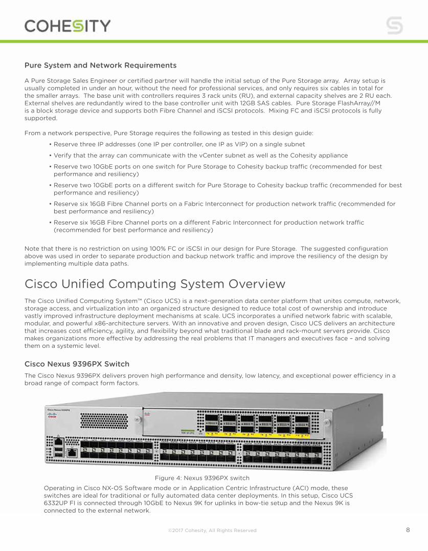
Cisco Nexus 9396PX SwitchThe Cisco Nexus 9396PX delivers proven high performance and density, low latency, and exceptional power efficiency in a broad range of compact form factors.
Figure 4: Nexus 9396PX switch
Operating in Cisco NX-OS Software mode or in Application Centric Infrastructure (ACI) mode, these switches are ideal for traditional or fully automated data center deployments. In this setup, Cisco UCS 6332UP FI is connected through 10GbE to Nexus 9K for uplinks in bow-tie setup and the Nexus 9K is connected to the external network.

©2017 Cohesity, All Rights Reserved 9
Cisco UCS 6332-16UP Fabric Interconnect
The 6332-16UP Fabric Interconnect is the management and communication backbone for Cisco UCS B-Series Blade Servers, C-Series Rack Servers, and 5100 Series Blade Server Chassis. All servers attached to a 6332-16UP Fabric Interconnect become part of one highly available management domain. The 6332-16UP is a core part of the Cisco Unified Computing System (Cisco UCS), and is typically deployed in redundant pairs. Because it supports unified fabric, the Cisco UCS 6300 Series Fabric Interconnect provides both LAN and SAN connectivity for all servers within its domain. The 6332-16UP offers 40 ports in one rack unit (RU), including:
• 24 40-Gigabit Ethernet and Fibre Channel over Ethernet (FCoE)
• 16 1- and 10-Gbps and FCoE or 4-,8-, and 16-Gbps Fibre Channel unified ports
Cisco Fabric Extender technology scales up to 20 chassis in a single unified system without additional complexity. This means that customers can eliminate dedicated chassis management and blade switches, as well as reduce cabling.
Cisco UCS 5100 Series Blade Server Chassis
Cisco’s first blade-server chassis offering, the Cisco UCS 5108 Blade Server Chassis is six rack units (6RU) high, can mount in an industry-standard 19-inch rack, and uses standard front-to-back cooling. A chassis can accommodate up to eight half-width or four full-width Cisco UCS B-Series Blade Server form factors within the same chassis.
Figure 5 : Cisco UCS 6332-16UP Fabric Interconnect
Figure 6 : UCS 5100 Blade Server Chassis
©2017 Cohesity, All Rights Reserved 10
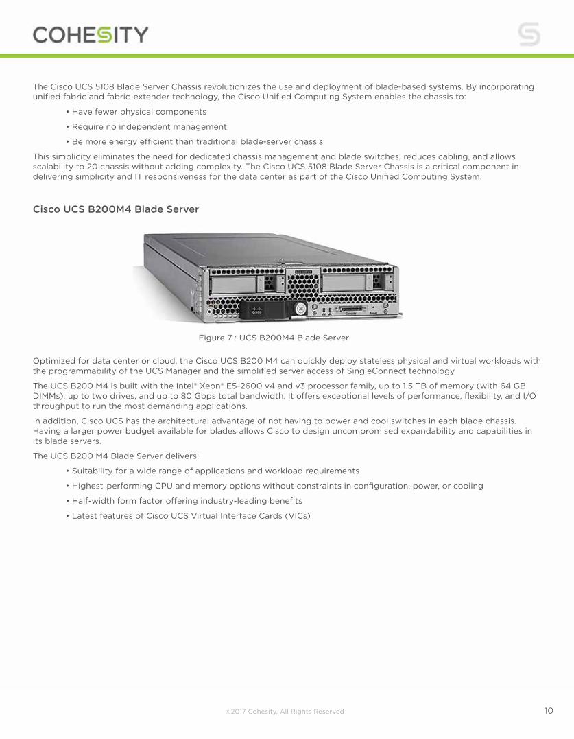
Cisco UCS B200M4 Blade Server
Optimized for data center or cloud, the Cisco UCS B200 M4 can quickly deploy stateless physical and virtual workloads with the programmability of the UCS Manager and the simplified server access of SingleConnect technology.
The UCS B200 M4 is built with the Intel® Xeon® E5-2600 v4 and v3 processor family, up to 1.5 TB of memory (with 64 GB DIMMs), up to two drives, and up to 80 Gbps total bandwidth. It offers exceptional levels of performance, flexibility, and I/O throughput to run the most demanding applications.
In addition, Cisco UCS has the architectural advantage of not having to power and cool switches in each blade chassis. Having a larger power budget available for blades allows Cisco to design uncompromised expandability and capabilities in its blade servers.
The UCS B200 M4 Blade Server delivers:
• Suitability for a wide range of applications and workload requirements
• Highest-performing CPU and memory options without constraints in configuration, power, or cooling
• Half-width form factor offering industry-leading benefits
• Latest features of Cisco UCS Virtual Interface Cards (VICs)
Figure 7 : UCS B200M4 Blade Server
The Cisco UCS 5108 Blade Server Chassis revolutionizes the use and deployment of blade-based systems. By incorporating unified fabric and fabric-extender technology, the Cisco Unified Computing System enables the chassis to:
• Have fewer physical components
• Require no independent management
• Be more energy efficient than traditional blade-server chassis
This simplicity eliminates the need for dedicated chassis management and blade switches, reduces cabling, and allows scalability to 20 chassis without adding complexity. The Cisco UCS 5108 Blade Server Chassis is a critical component in delivering simplicity and IT responsiveness for the data center as part of the Cisco Unified Computing System.
©2017 Cohesity, All Rights Reserved 11
Cohesity Overview
Physical ServersVMware
App ServersDatabase
NFS / SMB / REST
REST API
Cloud Tier
Tape / Cloud Archival
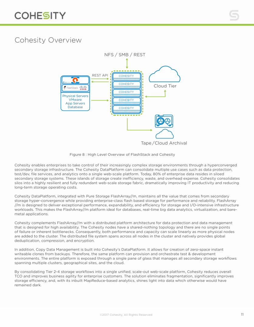
Figure 8 : High Level Overview of FlashStack and Cohesity
Cohesity enables enterprises to take control of their increasingly complex storage environments through a hyperconverged secondary storage infrastructure. The Cohesity DataPlatform can consolidate multiple use cases such as data protection, test/dev, file services, and analytics onto a single web-scale platform. Today, 80% of enterprise data resides in siloed secondary storage systems. These islands of storage create inefficiency, waste, and overhead expense. Cohesity consolidates silos into a highly resilient and fully redundant web-scale storage fabric, dramatically improving IT productivity and reducing long-term storage operating costs. Cohesity DataPlatform, integrated with Pure Storage FlashArray//m, maintains all the value that comes from secondary storage hyper-convergence while providing enterprise-class flash based storage for performance and reliability. FlashArray //m is designed to deliver exceptional performance, expandability, and efficiency for storage and I/O-intensive infrastructure workloads. This makes the FlashArray//m platform ideal for databases, real-time big data analytics, virtualization, and bare-metal applications. Cohesity complements FlashArray//m with a distributed platform architecture for data protection and data management that is designed for high availability. The Cohesity nodes have a shared-nothing topology and there are no single points of failure or inherent bottlenecks. Consequently, both performance and capacity can scale linearly as more physical nodes are added to the cluster. The distributed file system spans across all nodes in the cluster and natively provides global deduplication, compression, and encryption. In addition, Copy Data Management is built into Cohesity’s DataPlatform. It allows for creation of zero-space instant writeable clones from backups. Therefore, the same platform can provision and orchestrate test & development environments. The entire platform is exposed through a single pane of glass that manages all secondary storage workflows spanning multiple clusters, geographical sites, and the cloud. By consolidating Tier 2-4 storage workflows into a single unified, scale-out web-scale platform, Cohesity reduces overall TCO and improves business agility for enterprise customers. The solution eliminates fragmentation, significantly improves storage efficiency, and, with its inbuilt MapReduce-based analytics, shines light into data which otherwise would have remained dark.
©2017 Cohesity, All Rights Reserved 12
CBT Backups Cohesity leverages VMware’s vSphere API for Data Protection and Change Block Tracking (CBT) mechanism to ensure consistent and storage-efficient protection of VM data while keeping the data fully hydrated, indexed, and instantly available.
Deep dives on the Cohesity architecture and SnapTree(TM) that supports these capabilities can be found here: http://www.cohesity.com/wp-content/uploads/2015/10/Cohesity-Architecture-WhitePaper.pdf https://www.cohesity.com/resource-assets/solution-brief/Cohesity-SnapTree-Solution-Brief.pdf CBT is implemented at the VMware virtualization layer and can track virtual disk blocks that have been used and/or changed since a previous snapshot. This allows for very efficient storage of incremental changes to the virtual disk reducing both storage space as well as the overall time for backups to take place and in-turn replicate. For further information and supported configurations for CBT, please visit:
https://kb.vmware.com/selfservice/microsites/search.do?language=en_US&cmd=displayKC&externalId=1020128 By default, new VMs have CBT disabled. Cohesity’s DataProtect software will automatically detect this condition and enable CBT for the VMs that are configured for protection, removing the need for administrators to track CBT status.
Non-CBT Backups CBT backups are the most common form of Cohesity backups due to their space-efficient, fully-hydrated nature. However, Cohesity also provides the ability to take non-CBT backups. A policy-based backup allows for non-CBT backups as well, to provide an additional layer of data protection in case that is also required.
Pure Storage Overview Who knew that moving to all-flash storage could help reduce the cost of IT? FlashArray//m makes server and workload investments more productive, while also lowering storage spend. With FlashArray//m, organizations can dramatically reduce the complexity of storage to make IT more agile and efficient, accelerating the journey to the cloud. FlashArray//m’s performance can also make your business smarter by unleashing the power of real-time analytics, driving customer loyalty, and creating new, innovative customer experiences that simply weren’t possible with disk. All by transforming storage with FlashArray//m. FlashArray//m leverages a chassis-based design with customizable modules, enabling both capacity and performance to be independently improved over time with advances in compute and flash, to meet business needs today and tomorrow. The Pure Storage FlashArray is ideal for:
• Accelerating Databases and Applications: Speed transactions by 10x with consistent low latency, enable online data analytics across wide datasets, and mix production, analytics, dev/test, and backup workloads without fear.
• Virtualizing and Consolidating Workloads: Easily accommodate the most IO-hungry Tier 1 workloads, increase consolidation rates (thereby reducing servers), simplify VI administration, and accelerate common administrative tasks.
• Delivering the Ultimate Virtual Desktop Experience: Support demanding users with better performance than physical desktops, scale without disruption from pilot to >1000’s of users, and experience all-flash performance with simple management for under $50/desktop per year.
• Protecting and Recovering Vital Data Assets: Provide always-on protection for business-critical data, maintain performance even under failure conditions, and recover instantly with FlashRecover.
©2017 Cohesity, All Rights Reserved 13
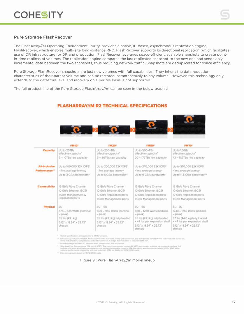
Pure Storage FlashRecover The FlashArray//M Operating Environment, Purity, provides a native, IP-based, asynchronous replication engine, FlashRecover, which enables multi-site long-distance RPO. FlashRecover supports bi-directional replication, which facilitates use of DR infrastructure for DR and production. FlashRecover leverages space-efficient, scalable snapshots to create point-in-time replicas of volumes. The replication engine compares the last replicated snapshot to the new one and sends only incremental data between the two snapshots, thus reducing network traffic. Snapshots are deduplicated for space efficiency. Pure Storage FlashRecover snapshots are just new volumes with full capabilities. They inherit the data reduction characteristics of their parent volume and can be restored instantaneously to any volume. However, this technology only extends to the datastore level and recovery on a per file basis is not supported. The full product line of the Pure Storage FlashArray//m can be seen in the below graphic.
Figure 9 : Pure FlashArray//m model lineup
©2017 Cohesity, All Rights Reserved 14
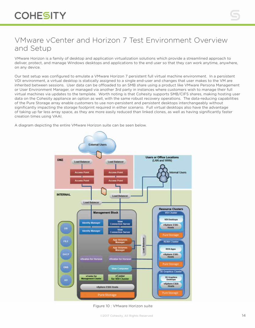
Figure 10 : VMware Horizon suite
VMware vCenter and Horizon 7 Test Environment Overview and Setup VMware Horizon is a family of desktop and application virtualization solutions which provide a streamlined approach to deliver, protect, and manage Windows desktops and applications to the end user so that they can work anytime, anywhere, on any device. Our test setup was configured to emulate a VMware Horizon 7 persistent full virtual machine environment. In a persistent VDI environment, a virtual desktop is statically assigned to a single end-user and changes that user makes to the VM are inherited between sessions. User data can be offloaded to an SMB share using a product like VMware Persona Management or User Environment Manager, or managed via another 3rd party in instances where customers wish to manage their full virtual machines via updates to the template. Worth noting is that Cohesity supports SMB/CIFS shares, making hosting user data on the Cohesity appliance an option as well, with the same robust recovery operations. The data-reducing capabilities of the Pure Storage array enable customers to use non-persistent and persistent desktops interchangeably without significantly impacting the storage footprint required in either scenario. Full virtual desktops also have the advantage of taking up far less array space, as they are more easily reduced than linked clones, as well as having significantly faster creation times using VAAI. A diagram depicting the entire VMware Horizon suite can be seen below.
©2017 Cohesity, All Rights Reserved 15
VDI has proven to be a tier-0 workload due to the burstiness and randomness that it places upon the underlying infrastructure, particularly storage, as well as the mission critical data and functions that it is responsible for. In this paper we will be using a subset of the available VMware Horizon components shown above; but important to note is that the number of dependencies and their interconnections to each other requires running on an all flash array like Pure Storage to provide acceptable sub-millisecond performance to the end-user. Moreover, all-flash is critical to maintaining sub-millisecond performance when typical administrative tasks that require a high amount of read and writes to the array (such as recompose) might adversely impact active end-users. Of equal importance is being able to both backup and restore a block of VMs, an individual VM, or even individual files within a single VM to recover from something as simple as a user accidentally deleting an important document or something much more nefarious like a ransomware attack.
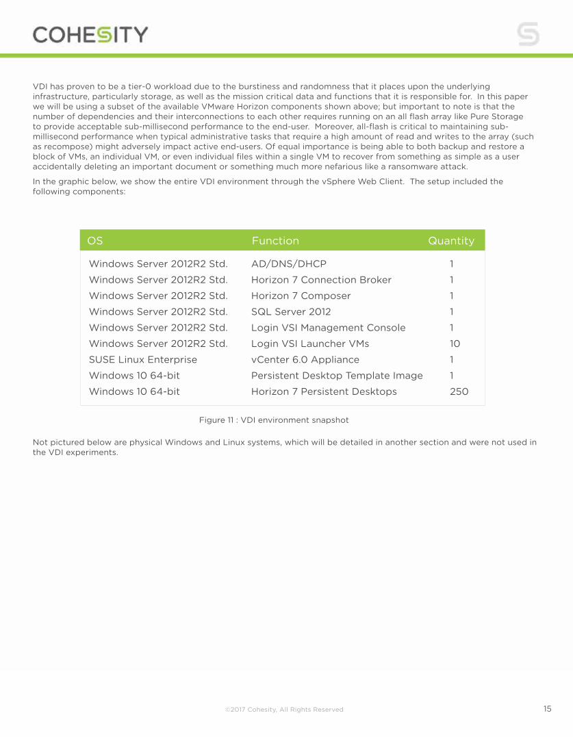
In the graphic below, we show the entire VDI environment through the vSphere Web Client. The setup included the following components:
Not pictured below are physical Windows and Linux systems, which will be detailed in another section and were not used in the VDI experiments.
OS Function Quantity
Windows Server 2012R2 Std.
Windows Server 2012R2 Std.
Windows Server 2012R2 Std.
Windows Server 2012R2 Std.
Windows Server 2012R2 Std.
Windows Server 2012R2 Std.
SUSE Linux Enterprise
Windows 10 64-bit
Windows 10 64-bit
AD/DNS/DHCP
Horizon 7 Connection Broker
Horizon 7 Composer
SQL Server 2012
Login VSI Management Console
Login VSI Launcher VMs
vCenter 6.0 Appliance
Persistent Desktop Template Image
Horizon 7 Persistent Desktops
1
1
1
1
1
10
1
1
250
Figure 11 : VDI environment snapshot
©2017 Cohesity, All Rights Reserved 16
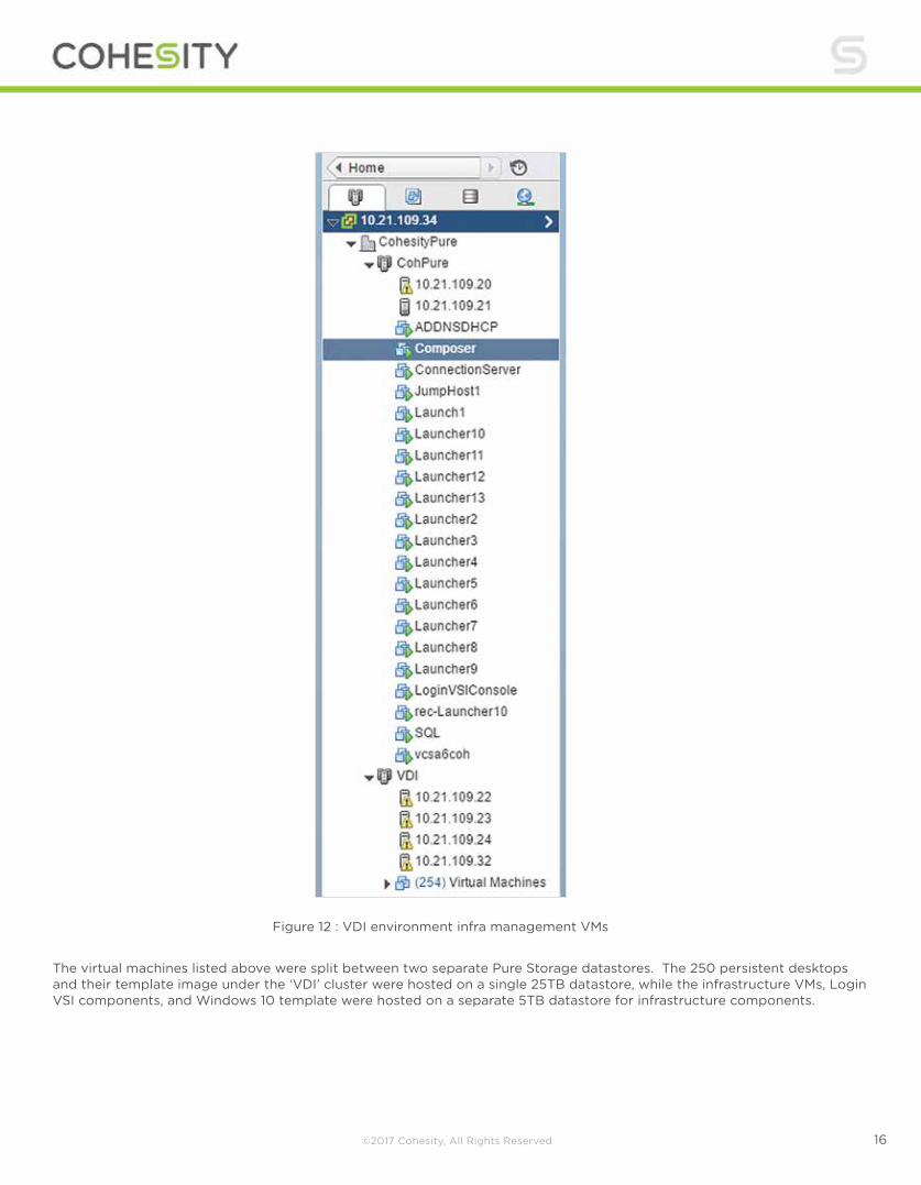
Figure 12 : VDI environment infra management VMs
The virtual machines listed above were split between two separate Pure Storage datastores. The 250 persistent desktops and their template image under the ‘VDI’ cluster were hosted on a single 25TB datastore, while the infrastructure VMs, Login VSI components, and Windows 10 template were hosted on a separate 5TB datastore for infrastructure components.

©2017 Cohesity, All Rights Reserved 17
Figure 13 : Pure FlashArray//m Datastores running VDI and Infrastructure Env.
This environment can easily be linearly scaled to thousands of desktops by adding additional ESXi hosts and infrastructure virtual servers (e.g. AD/DNS/DHCP, Horizon Connection Servers) in order to provide the necessary compute and load balancing for the additional users. Since the purpose of this paper is to demonstrate the integration and workflows between Pure Storage, Cisco UCS, and Cohesity, we elected to keep this ecosystem relatively small - though all actions performed throughout can easily be leveraged for use with a much larger deployment and for workloads outside of, and mixed with, VDI.
The Windows 10 user desktops included the standard set of Knowledge Worker tools used by Login VSI for simulating user workflows, including: Office® 2013 Suite, Adobe Acrobat Reader®, Internet Explorer®, 7zip, and DoroPDF writer, amongst others. We used the VMware Horizon OS Optimization tool to setup the parent VM properly.
From a networking perspective, two separate networks with two vNICs each (for failover) were used in our test environment: one for ESXi host management traffic and Cohesity and Pure Storage integration, and a second network dedicated for VDI desktop traffic between desktop VMs and the simulated Login VSI endpoint devices exercising the environment. Segregating network traffic in this manner is an important consideration for both performance as well as resiliency concerns.
The screen capture below shows the configuration used for the persistent VDI desktop pool. Important to note is that for these experiments we elected to use a persistent full virtual machine cloned from a template. All user state changes are inherited between sessions using this model. Alternative methods for hosting user data such as Persona Management, User Experience Manager, AppVolumes, and/or a third party tool would all be supportable options within this solution
Figure 14 : VMware Horizon Desktop Pool Settings

©2017 Cohesity, All Rights Reserved 18
Figure 15 : VMware Horizon Desktop Pool Settings
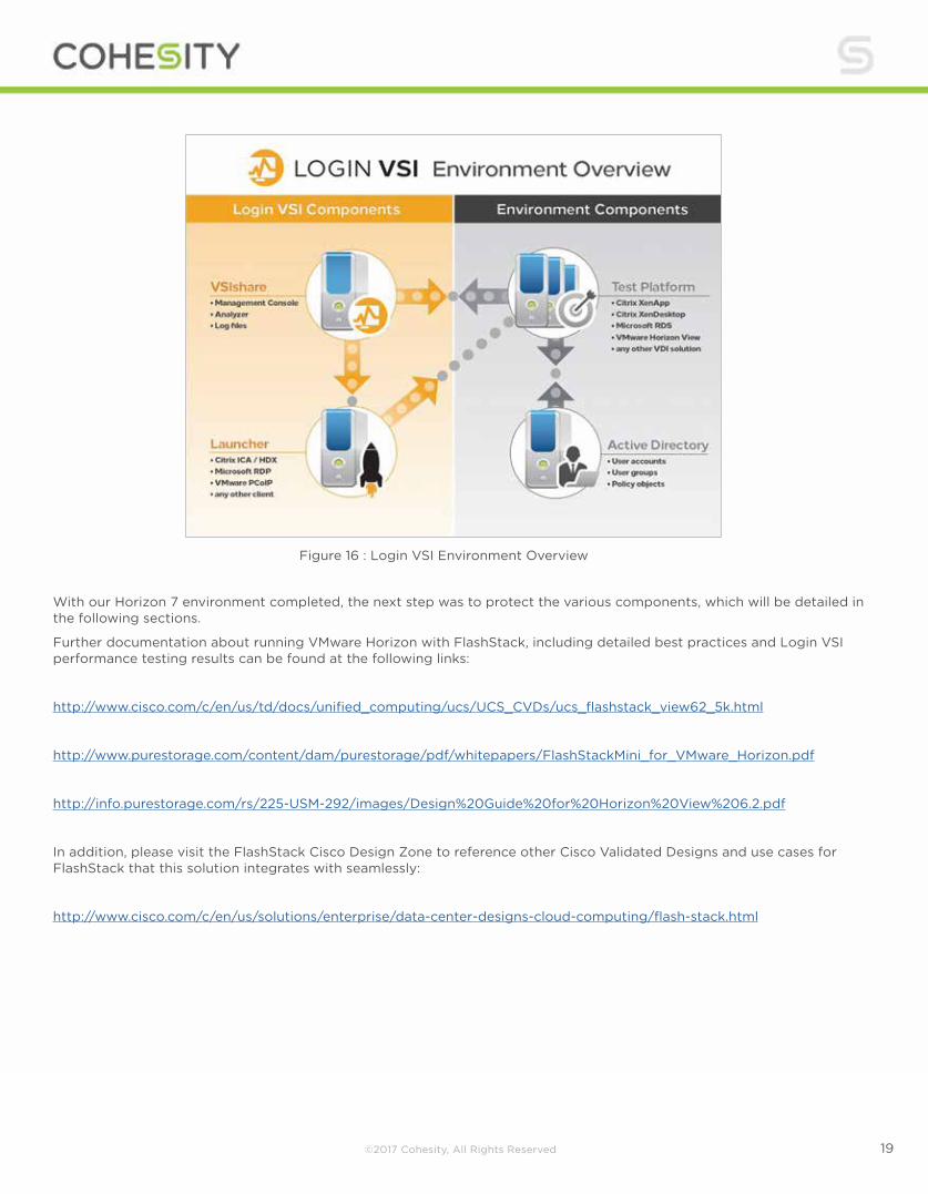
As mentioned earlier, a vital piece of the test environment was setting up Login VSI to provide realistic, user-driven changes to the end-user desktops that could then be protected and potentially restored by the Cohesity appliance in the event of a VM or data file corruption. The diagram below shows the required connections and components we used to create a realistic Horizon 7 production deployment. Login VSI provides the most realistic and industry-standard VDI benchmarking available on the market. Further information about Login VSI can be found at their website: http://www.loginvsi.com.
©2017 Cohesity, All Rights Reserved 19
Figure 16 : Login VSI Environment Overview
With our Horizon 7 environment completed, the next step was to protect the various components, which will be detailed in the following sections.
Further documentation about running VMware Horizon with FlashStack, including detailed best practices and Login VSI performance testing results can be found at the following links:
http://www.cisco.com/c/en/us/td/docs/unified_computing/ucs/UCS_CVDs/ucs_flashstack_view62_5k.html
http://www.purestorage.com/content/dam/purestorage/pdf/whitepapers/FlashStackMini_for_VMware_Horizon.pdf
http://info.purestorage.com/rs/225-USM-292/images/Design%20Guide%20for%20Horizon%20View%206.2.pdf
In addition, please visit the FlashStack Cisco Design Zone to reference other Cisco Validated Designs and use cases for FlashStack that this solution integrates with seamlessly:
http://www.cisco.com/c/en/us/solutions/enterprise/data-center-designs-cloud-computing/flash-stack.html
©2017 Cohesity, All Rights Reserved 20
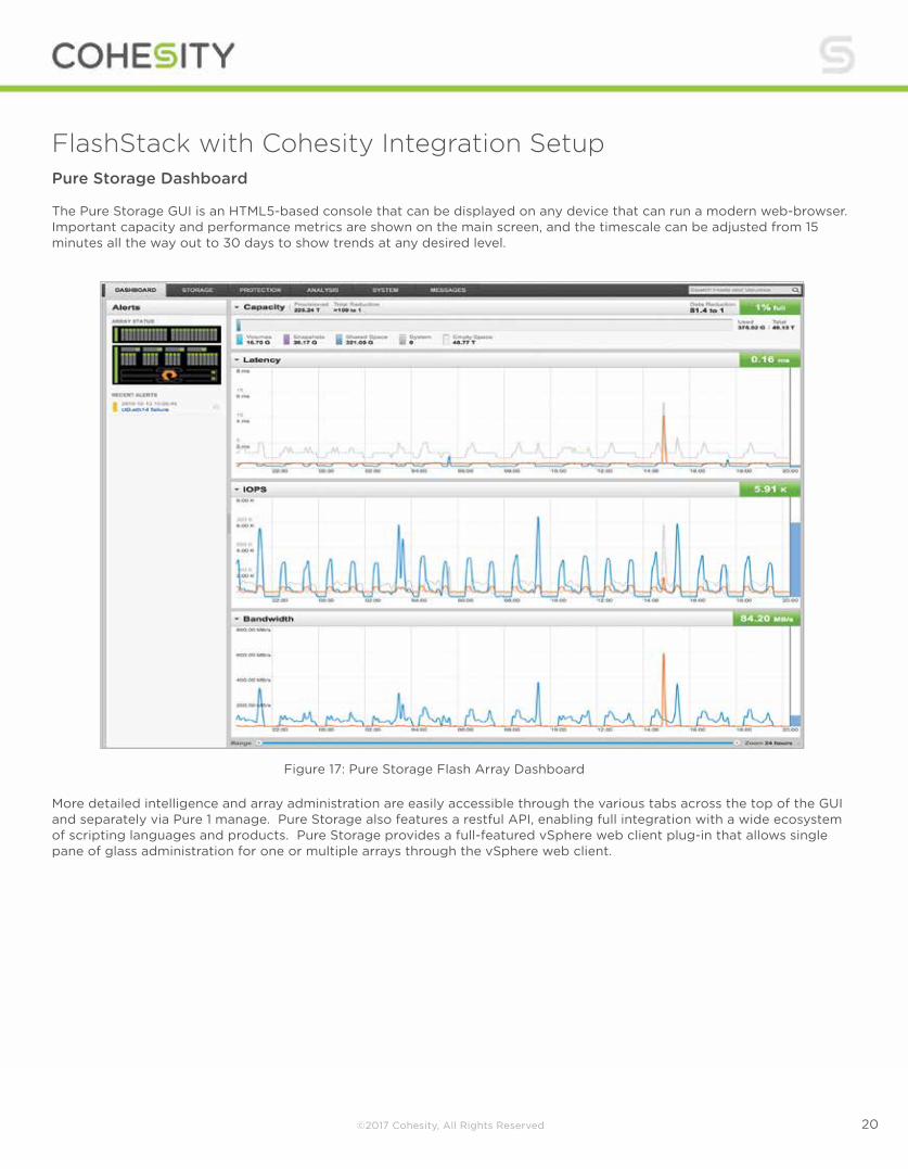
FlashStack with Cohesity Integration Setup Pure Storage Dashboard The Pure Storage GUI is an HTML5-based console that can be displayed on any device that can run a modern web-browser. Important capacity and performance metrics are shown on the main screen, and the timescale can be adjusted from 15 minutes all the way out to 30 days to show trends at any desired level.
More detailed intelligence and array administration are easily accessible through the various tabs across the top of the GUI and separately via Pure 1 manage. Pure Storage also features a restful API, enabling full integration with a wide ecosystem of scripting languages and products. Pure Storage provides a full-featured vSphere web client plug-in that allows single pane of glass administration for one or multiple arrays through the vSphere web client.
Figure 17: Pure Storage Flash Array Dashboard
©2017 Cohesity, All Rights Reserved 21
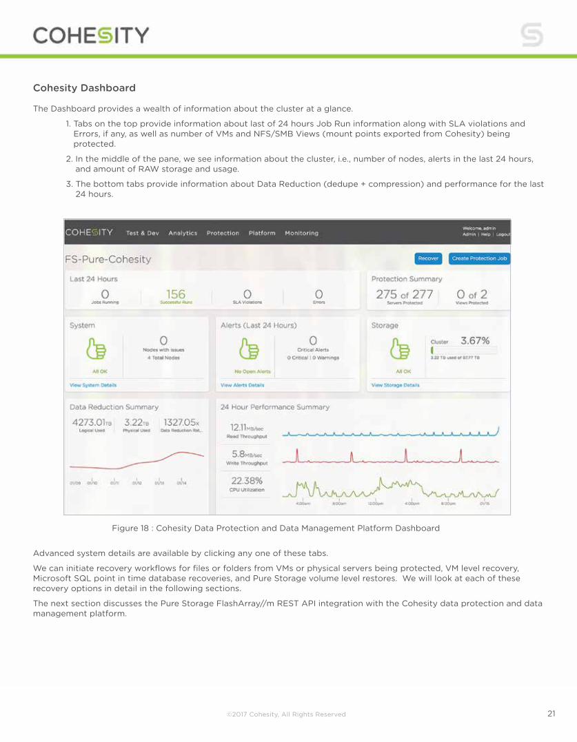
Cohesity Dashboard The Dashboard provides a wealth of information about the cluster at a glance.
1. Tabs on the top provide information about last of 24 hours Job Run information along with SLA violations and Errors, if any, as well as number of VMs and NFS/SMB Views (mount points exported from Cohesity) being protected.
2. In the middle of the pane, we see information about the cluster, i.e., number of nodes, alerts in the last 24 hours, and amount of RAW storage and usage.
3. The bottom tabs provide information about Data Reduction (dedupe + compression) and performance for the last 24 hours.
Advanced system details are available by clicking any one of these tabs.
We can initiate recovery workflows for files or folders from VMs or physical servers being protected, VM level recovery, Microsoft SQL point in time database recoveries, and Pure Storage volume level restores. We will look at each of these recovery options in detail in the following sections.
The next section discusses the Pure Storage FlashArray//m REST API integration with the Cohesity data protection and data management platform.
Figure 18 : Cohesity Data Protection and Data Management Platform Dashboard
©2017 Cohesity, All Rights Reserved 22
Flash Array//m Integration, Protection and Recovery
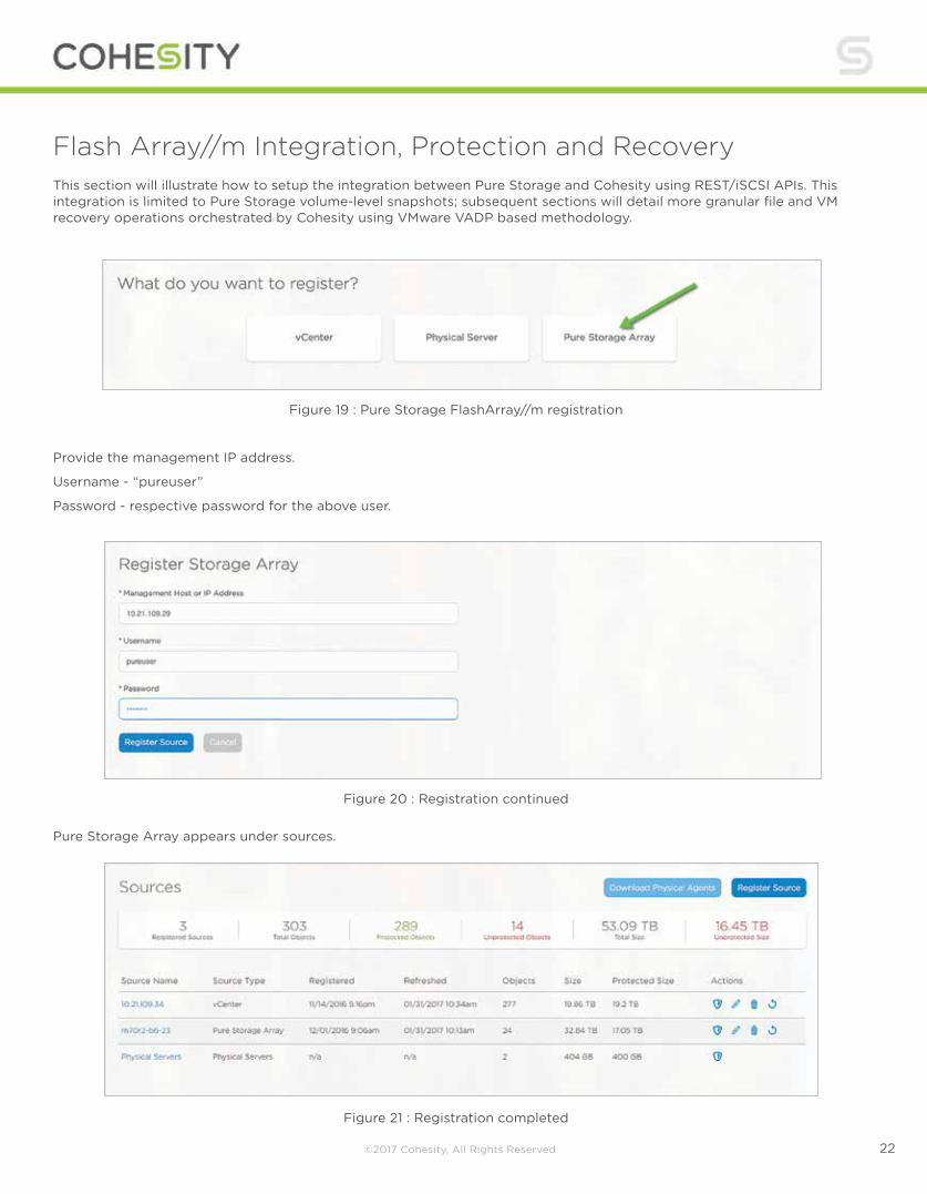
Provide the management IP address.
Username - “pureuser”
Password - respective password for the above user.
This section will illustrate how to setup the integration between Pure Storage and Cohesity using REST/iSCSI APIs. This integration is limited to Pure Storage volume-level snapshots; subsequent sections will detail more granular file and VM recovery operations orchestrated by Cohesity using VMware VADP based methodology.
Pure Storage Array appears under sources.
Figure 19 : Pure Storage FlashArray//m registration
Figure 20 : Registration continued
Figure 21 : Registration completed
©2017 Cohesity, All Rights Reserved 23
Registration: Step 1: User enters the address of the Pure array along with credentials.
Step 2: Connect to the Pure array and query the list of volumes on it. The list of volumes is cached internally and shown to the user when they want to create backup jobs, etc.
Step 3: All IQNs from the Cohesity nodes are registered as a single host on the Pure array.
A. This is done by creating a single host that has multiple IQNS on Pure.
B. The IQNs correspond to the initiator IQNs of all the nodes in the Cohesity cluster.
Once the Pure Storage FlashArray//m has been registered, a protection policy and job to protect the storage Volumes is configured.
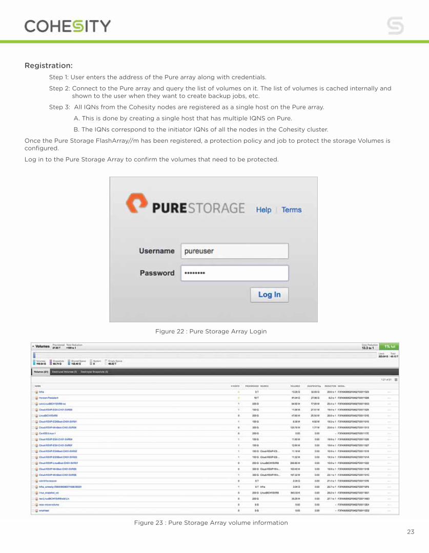
Log in to the Pure Storage Array to confirm the volumes that need to be protected.
Figure 22 : Pure Storage Array Login
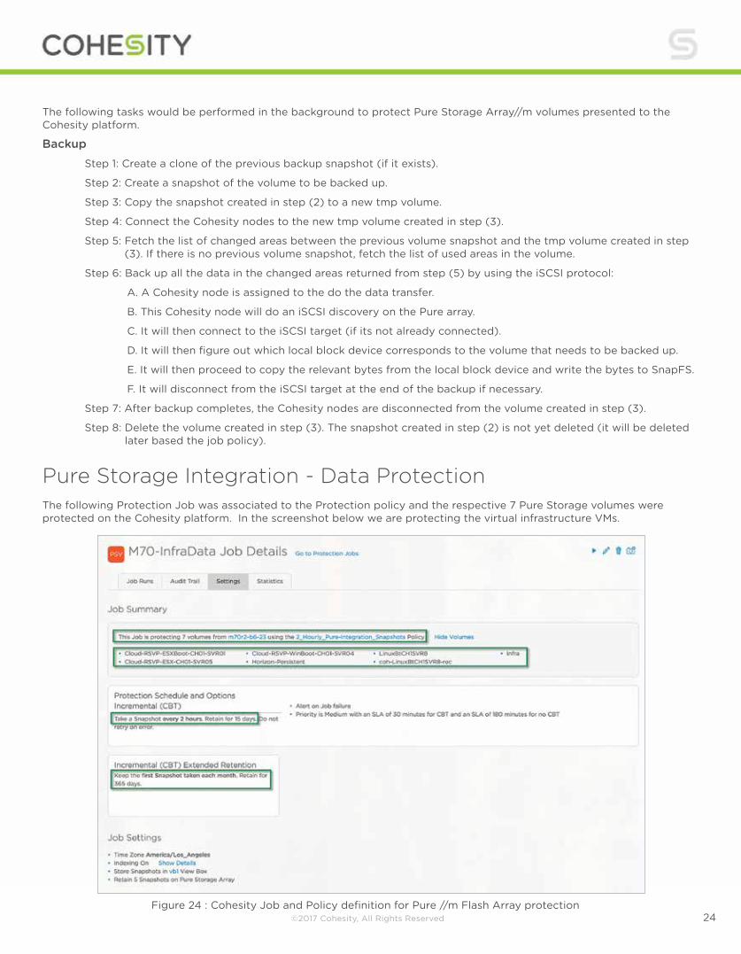
Figure 23 : Pure Storage Array volume information
©2017 Cohesity, All Rights Reserved 24
The following tasks would be performed in the background to protect Pure Storage Array//m volumes presented to the Cohesity platform.
Backup Step 1: Create a clone of the previous backup snapshot (if it exists).
Step 2: Create a snapshot of the volume to be backed up.
Step 3: Copy the snapshot created in step (2) to a new tmp volume.
Step 4: Connect the Cohesity nodes to the new tmp volume created in step (3).
Step 5: Fetch the list of changed areas between the previous volume snapshot and the tmp volume created in step (3). If there is no previous volume snapshot, fetch the list of used areas in the volume.
Step 6: Back up all the data in the changed areas returned from step (5) by using the iSCSI protocol:
A. A Cohesity node is assigned to the do the data transfer.
B. This Cohesity node will do an iSCSI discovery on the Pure array.
C. It will then connect to the iSCSI target (if its not already connected).
D. It will then figure out which local block device corresponds to the volume that needs to be backed up.
E. It will then proceed to copy the relevant bytes from the local block device and write the bytes to SnapFS.
F. It will disconnect from the iSCSI target at the end of the backup if necessary.
Step 7: After backup completes, the Cohesity nodes are disconnected from the volume created in step (3).
Step 8: Delete the volume created in step (3). The snapshot created in step (2) is not yet deleted (it will be deleted later based the job policy).
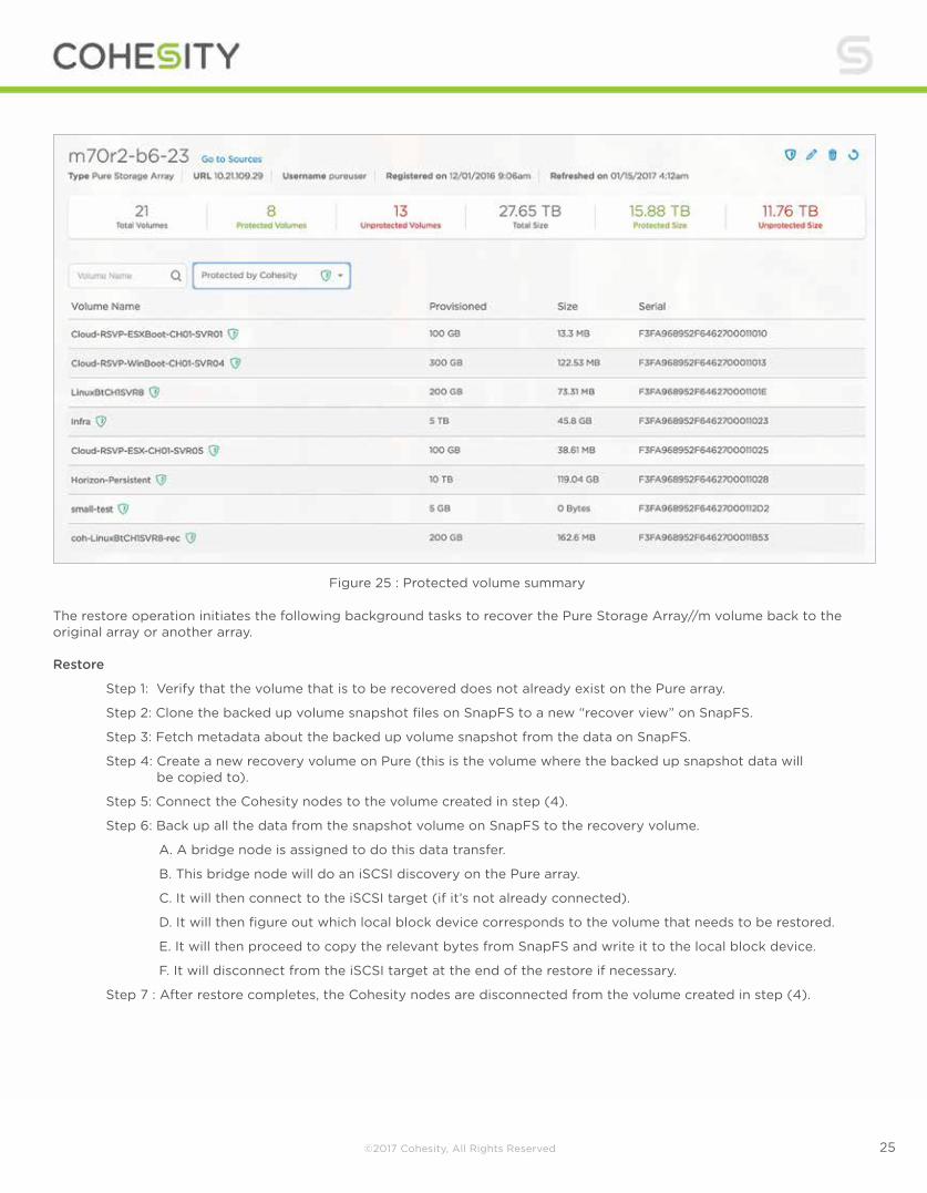
Pure Storage Integration - Data Protection The following Protection Job was associated to the Protection policy and the respective 7 Pure Storage volumes were protected on the Cohesity platform. In the screenshot below we are protecting the virtual infrastructure VMs.
Figure 24 : Cohesity Job and Policy definition for Pure //m Flash Array protection
©2017 Cohesity, All Rights Reserved 25
The restore operation initiates the following background tasks to recover the Pure Storage Array//m volume back to the original array or another array. Restore
Step 1: Verify that the volume that is to be recovered does not already exist on the Pure array.
Step 2: Clone the backed up volume snapshot files on SnapFS to a new “recover view” on SnapFS.
Step 3: Fetch metadata about the backed up volume snapshot from the data on SnapFS.
Step 4: Create a new recovery volume on Pure (this is the volume where the backed up snapshot data will be copied to).
Step 5: Connect the Cohesity nodes to the volume created in step (4).
Step 6: Back up all the data from the snapshot volume on SnapFS to the recovery volume.
A. A bridge node is assigned to do this data transfer.
B. This bridge node will do an iSCSI discovery on the Pure array.
C. It will then connect to the iSCSI target (if it’s not already connected).
D. It will then figure out which local block device corresponds to the volume that needs to be restored.
E. It will then proceed to copy the relevant bytes from SnapFS and write it to the local block device.
F. It will disconnect from the iSCSI target at the end of the restore if necessary.
Step 7 : After restore completes, the Cohesity nodes are disconnected from the volume created in step (4).
Figure 25 : Protected volume summary
©2017 Cohesity, All Rights Reserved 26
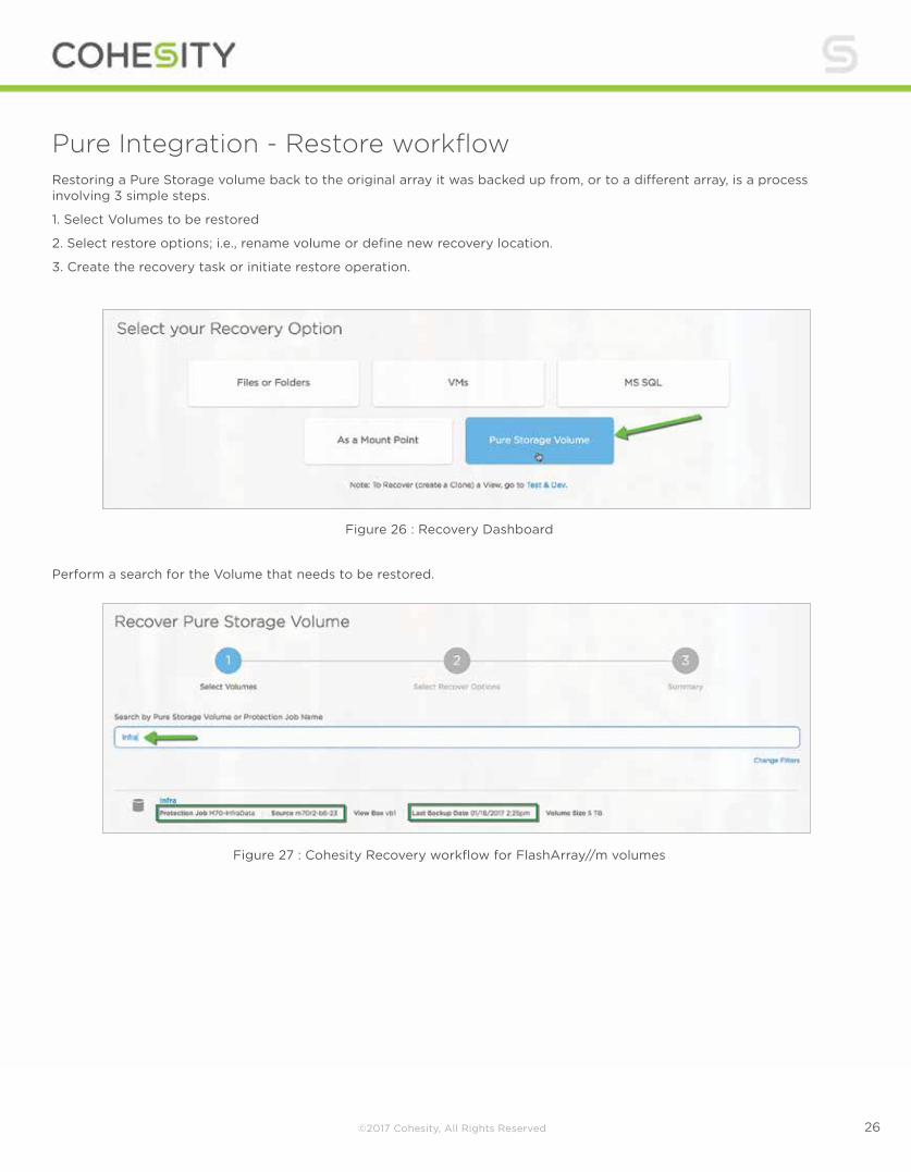
Pure Integration - Restore workflow Restoring a Pure Storage volume back to the original array it was backed up from, or to a different array, is a process involving 3 simple steps.
1. Select Volumes to be restored
2. Select restore options; i.e., rename volume or define new recovery location.
3. Create the recovery task or initiate restore operation.
Perform a search for the Volume that needs to be restored.
Figure 26 : Recovery Dashboard
Figure 27 : Cohesity Recovery workflow for FlashArray//m volumes

©2017 Cohesity, All Rights Reserved 27
Select the respective point of recovery from the available recovery points for the volume.
Figure 28 : Cohesity Recovery workflow for FlashArray//m volumes - continued
Figure 29 : Cohesity Recovery workflow for FlashArray//m volumes
In this particular case, the volume is being recovered back to the original //m array it was originally backed up from. Cohesity does support restoring volumes to a different array, as long as the array is registered in Cohesity and is also running the same version of Purity OS (4.7.6) as the original array.

©2017 Cohesity, All Rights Reserved 28
In this particular case, we are recovering an existing volume back to the original //m array it was originally backed up from. Cohesity does support restoring volumes to a different array, as long as the array is registered in Cohesity and is also running the same version of Purity OS (4.7.6) as the original array.
Once the volume has been recovered, the task of connecting hosts can be performed.
To re-attach a recovered Pure Storage LUN to vSphere, the process is very straightforward:
1. From within the Pure Storage GUI (standalone or vSphere web client plug-in), attach Host and/or Host Groups to the restored Volume.
2. Within the vSphere Web Client, re-add and re-signature the volume.
3. Re-add the virtual machines to the vSphere inventory.
Figure 30 : Cohesity Recovery workflow for FlashArray//m volumes
Figure 31 : Pure Storage FlashArray//m volume recovery workflow
©2017 Cohesity, All Rights Reserved 29
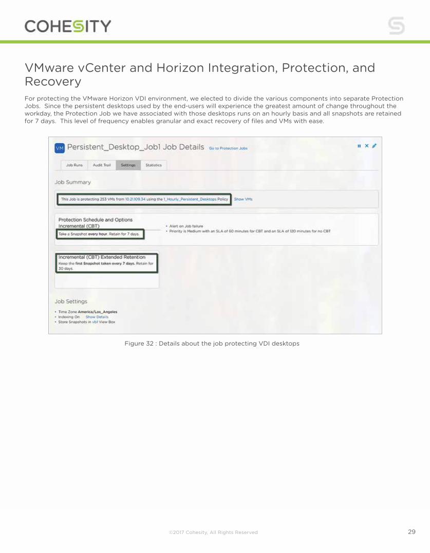
VMware vCenter and Horizon Integration, Protection, and Recovery For protecting the VMware Horizon VDI environment, we elected to divide the various components into separate Protection Jobs. Since the persistent desktops used by the end-users will experience the greatest amount of change throughout the workday, the Protection Job we have associated with those desktops runs on an hourly basis and all snapshots are retained for 7 days. This level of frequency enables granular and exact recovery of files and VMs with ease.
Figure 32 : Details about the job protecting VDI desktops
©2017 Cohesity, All Rights Reserved 30
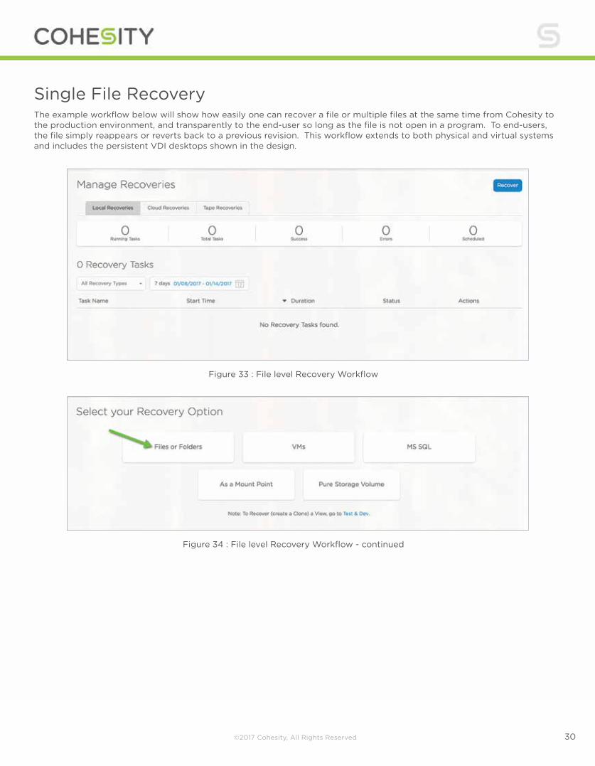
Single File Recovery The example workflow below will show how easily one can recover a file or multiple files at the same time from Cohesity to the production environment, and transparently to the end-user so long as the file is not open in a program. To end-users, the file simply reappears or reverts back to a previous revision. This workflow extends to both physical and virtual systems and includes the persistent VDI desktops shown in the design.
Figure 33 : File level Recovery Workflow
Figure 34 : File level Recovery Workflow - continued

©2017 Cohesity, All Rights Reserved 31
File Folder search -- Search is global across the entire dataset. There are 2 search options for files or folders.
Option 1 :
Search for a file or folder name and then filter if required to specific servers.
Option 2 :
Search for files folders by browsing specific servers or desktops.
Figure 35 : File level Recovery Workflow - continued
Figure 36 : File level Recovery Workflow - continued
©2017 Cohesity, All Rights Reserved 32
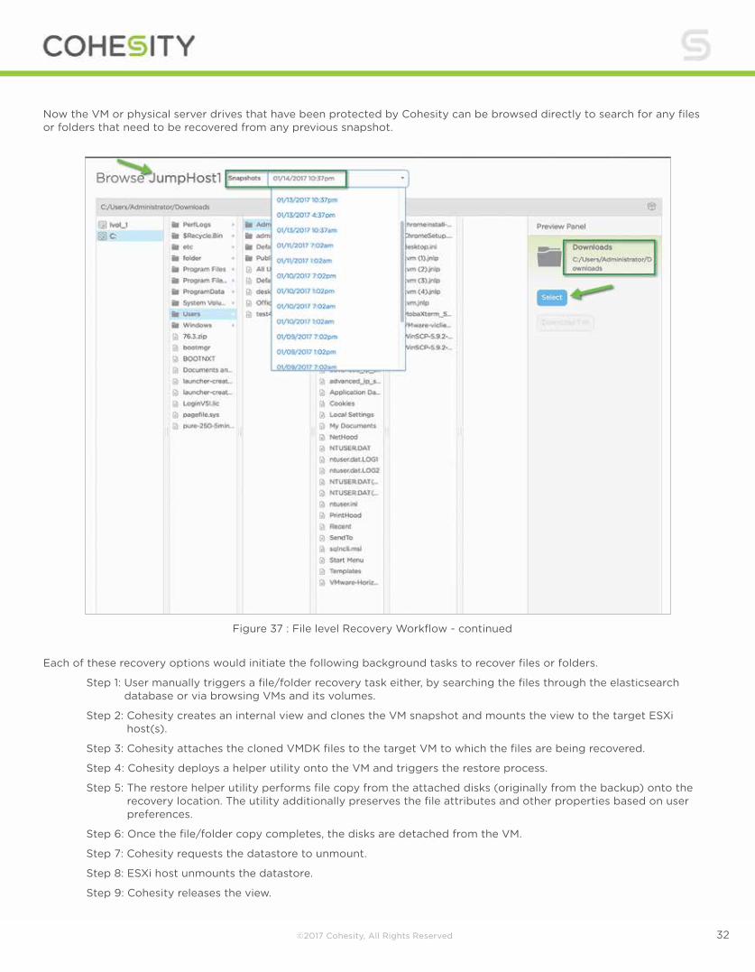
Now the VM or physical server drives that have been protected by Cohesity can be browsed directly to search for any files or folders that need to be recovered from any previous snapshot.
Each of these recovery options would initiate the following background tasks to recover files or folders.
Step 1: User manually triggers a file/folder recovery task either, by searching the files through the elasticsearch database or via browsing VMs and its volumes.
Step 2: Cohesity creates an internal view and clones the VM snapshot and mounts the view to the target ESXi host(s).
Step 3: Cohesity attaches the cloned VMDK files to the target VM to which the files are being recovered.
Step 4: Cohesity deploys a helper utility onto the VM and triggers the restore process.
Step 5: The restore helper utility performs file copy from the attached disks (originally from the backup) onto the recovery location. The utility additionally preserves the file attributes and other properties based on user preferences.
Step 6: Once the file/folder copy completes, the disks are detached from the VM.
Step 7: Cohesity requests the datastore to unmount.
Step 8: ESXi host unmounts the datastore.
Step 9: Cohesity releases the view.
Figure 37 : File level Recovery Workflow - continued

©2017 Cohesity, All Rights Reserved 33
Instant VM recovery
Searching for the VM by name presents two options for recovery.
Option 1
Recover the job that protects the VM in question and hence recover all VMs in the job as part of a single operation, instantly. This is sometimes very important if the VM is part of a group of VMs that needs to be recovered as they might all have been affected by a ransomware attack.
Option 2
Select just the VM to be recovered and recover it individually.
Here are the two recovery options presented in the Recover VM workflow:
Figure 38 : VM recovery tab
Figure 39 : VM recovery workflow

©2017 Cohesity, All Rights Reserved 34
Add the selected VM to the Shopping Cart, and then search for other VMs, if required, to make multiple VMs part of the same recovery operation.
For the purpose of this document, we are going to showcase Option 2.
Figure 40 : VM recovery workflow - continued
Figure 41 : VM recovery workflow - continued

©2017 Cohesity, All Rights Reserved 35
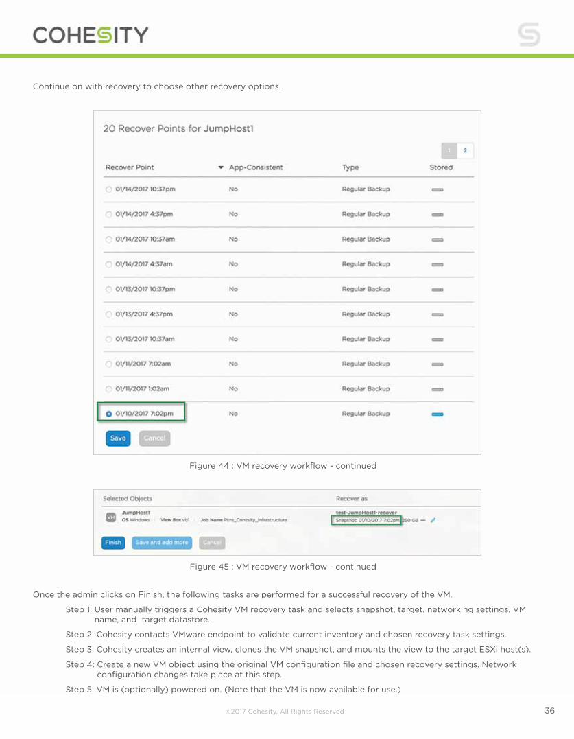
Continue on with recovery to choose other recovery options.
Figure 42 : VM recovery workflow - continued
Figure 43 : VM recovery workflow - continued
©2017 Cohesity, All Rights Reserved 36
Continue on with recovery to choose other recovery options.
Figure 44 : VM recovery workflow - continued
Figure 45 : VM recovery workflow - continued
Once the admin clicks on Finish, the following tasks are performed for a successful recovery of the VM.
Step 1: User manually triggers a Cohesity VM recovery task and selects snapshot, target, networking settings, VM name, and target datastore.
Step 2: Cohesity contacts VMware endpoint to validate current inventory and chosen recovery task settings.
Step 3: Cohesity creates an internal view, clones the VM snapshot, and mounts the view to the target ESXi host(s).
Step 4: Create a new VM object using the original VM configuration file and chosen recovery settings. Network configuration changes take place at this step.
Step 5: VM is (optionally) powered on. (Note that the VM is now available for use.)

©2017 Cohesity, All Rights Reserved 37
Step 6: Storage vMotion is initiated to move the datastore from the Cohesity cluster to the primary datastore.
Step 7: Storage vMotion completes. VMware non-disruptively migrates datastore access from the Cohesity cluster snapshot to the primary data store.
Step 8: Cohesity requests the datastore to unmount.
Step 9: ESXi host unmounts datastore.
Step 10: Cohesity releases the view.
Figure 46 : VM recovery workflow - continued
Figure 47 : VM recovery workflow - continued

©2017 Cohesity, All Rights Reserved 38
Post relocation, the VM would be running on the production Pure Storage datastore “Infrastructure”, as this was its original datastore.
Physical Server Integration, Backup, and Recovery Step 1: The master component of the DataProtect software on the Cohesity cluster triggers a scheduled backup job run or the job is manually triggered by a user.
Step 2: The master distributes the task of backing up individual servers across different slaves. Essentially, all the
nodes in the cluster take part in the backup. If any of the nodes goes down either due to failure or due to upgrade, the underlying architecture allows seamless migration of the tasks to a different node and does not affect the backup runs.
Step 3: The Cohesity cluster contacts Cohesity agent running on the physical server, collects information regarding
volumes, and checks health.
Step 4: The Cohesity cluster then triggers a snapshot on the server via the agent.
Step 5: The Cohesity agent performs environment-specific steps. 5 {Windows} On Windows this results in a VSS
snapshot being taken. Additionally, it will also contact the Cohesity change block tracking driver to fetch the blocks changed since the last backup in case of incremental backup. 5 {Linux} On Linux this triggers an LVM snapshot of the volumes.
Step 6: Cohesity backs up volumes from the server in a parallel fashion, distributing across several Cohesity nodes
but limiting to a number so that the primary remains unaffected.
Step 7: The volumes backed up will be saved as fully hydrated VHD/VHDx files onto Cohesity’s view.
Step 8: Once the snapshot is backed up, the Cohesity cluster will indicate to the agent that the backup completed
successfully.
Figure 48 : VM recovery workflow - continued

©2017 Cohesity, All Rights Reserved 39
Step 9: The Cohesity agent on Windows notifies the VSS component that the backup completed successfully.
Step 10: The snapshot is released on the server.
Step 11: The Cohesity cluster proceeds to index the files on the VHD/VHDx files and wraps up the backup job run. Physical Server - Data Protection Follow the steps to register, install agent, and protect a physical Windows 2012R2 server with Cohesity DataPlatform. Download or copy the Cohesity physical agent onto the system which is to be protected.
Download the respective agent for the respective OS.
Figure 49 : Download physical agents
Figure 50 : Download physical agents - continued

©2017 Cohesity, All Rights Reserved 40
In four simple steps the agent is installed on the physical server. The server requires a reboot once the agent has been installed as the agent enables CBT on the physical volumes.
Figure 51 : Installing physical agents on Windows
Figure 52,53 : Installing physical agents on Windows - continued
Figure 54,55 : Installing physical agents on Windows - continued

©2017 Cohesity, All Rights Reserved 41
Now we are ready to register and protect the physical server.
Figure 56 : Registering physical Windows server
Figure 58 : Registered physical server
Figure 57 : Registering physical Windows server - continued

©2017 Cohesity, All Rights Reserved 42
Now we can select the volumes/drives on the server to be protected.
Individual drive letters/volumes can be selected for data protection, or by default all volumes are protected.
Associate the job with a respective policy.
Figure 59 : Protect physical server
Figure 60 : Protect physical server - continued
Figure 61 : Protect physical server - continued

©2017 Cohesity, All Rights Reserved 43
Figure 62 : Protect physical server - continued
Figure 63 : Protect physical server - continued
©2017 Cohesity, All Rights Reserved 44
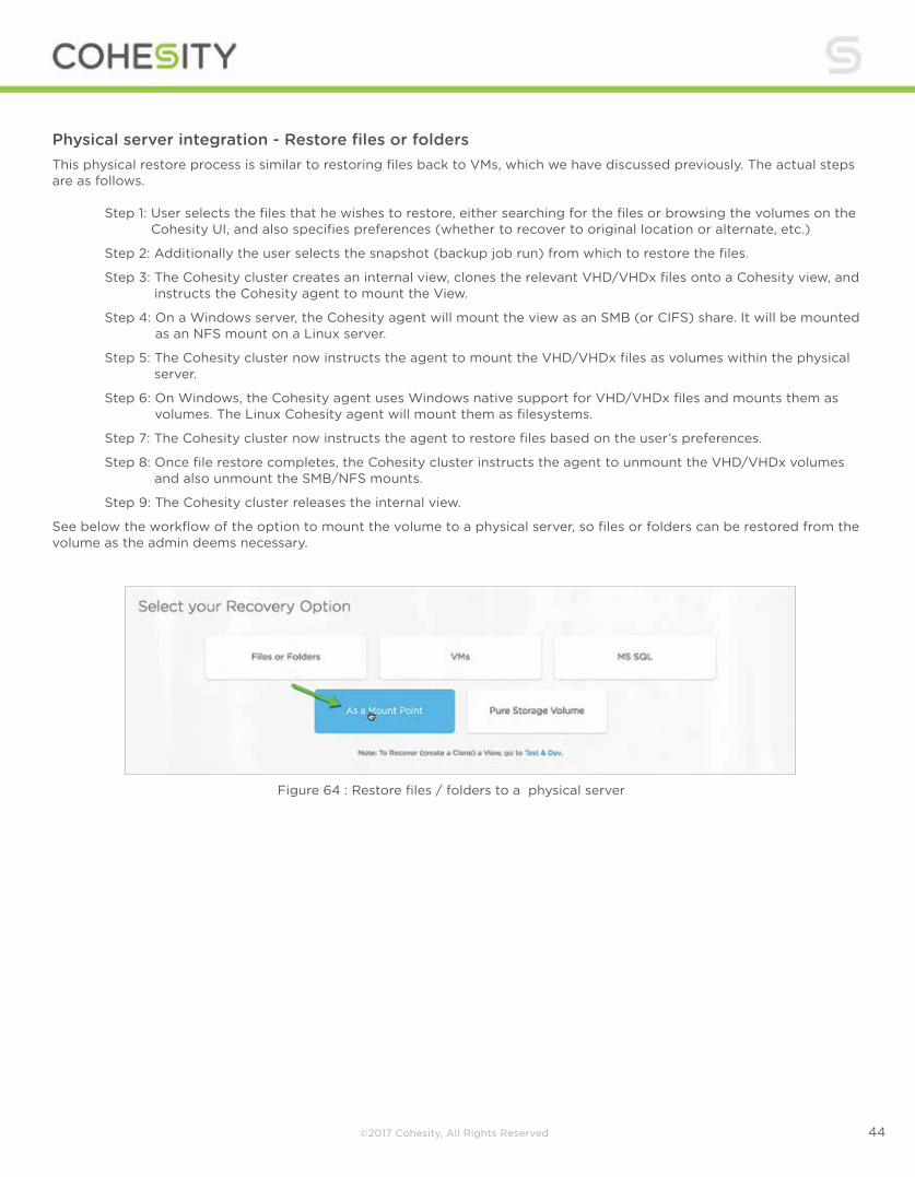
Physical server integration - Restore files or folders This physical restore process is similar to restoring files back to VMs, which we have discussed previously. The actual steps are as follows. Step 1: User selects the files that he wishes to restore, either searching for the files or browsing the volumes on the
Cohesity UI, and also specifies preferences (whether to recover to original location or alternate, etc.)
Step 2: Additionally the user selects the snapshot (backup job run) from which to restore the files.
Step 3: The Cohesity cluster creates an internal view, clones the relevant VHD/VHDx files onto a Cohesity view, and instructs the Cohesity agent to mount the View.
Step 4: On a Windows server, the Cohesity agent will mount the view as an SMB (or CIFS) share. It will be mounted as an NFS mount on a Linux server.
Step 5: The Cohesity cluster now instructs the agent to mount the VHD/VHDx files as volumes within the physical server.
Step 6: On Windows, the Cohesity agent uses Windows native support for VHD/VHDx files and mounts them as volumes. The Linux Cohesity agent will mount them as filesystems.
Step 7: The Cohesity cluster now instructs the agent to restore files based on the user’s preferences.
Step 8: Once file restore completes, the Cohesity cluster instructs the agent to unmount the VHD/VHDx volumes and also unmount the SMB/NFS mounts.
Step 9: The Cohesity cluster releases the internal view.
See below the workflow of the option to mount the volume to a physical server, so files or folders can be restored from the volume as the admin deems necessary.
Figure 64 : Restore files / folders to a physical server
©2017 Cohesity, All Rights Reserved 45
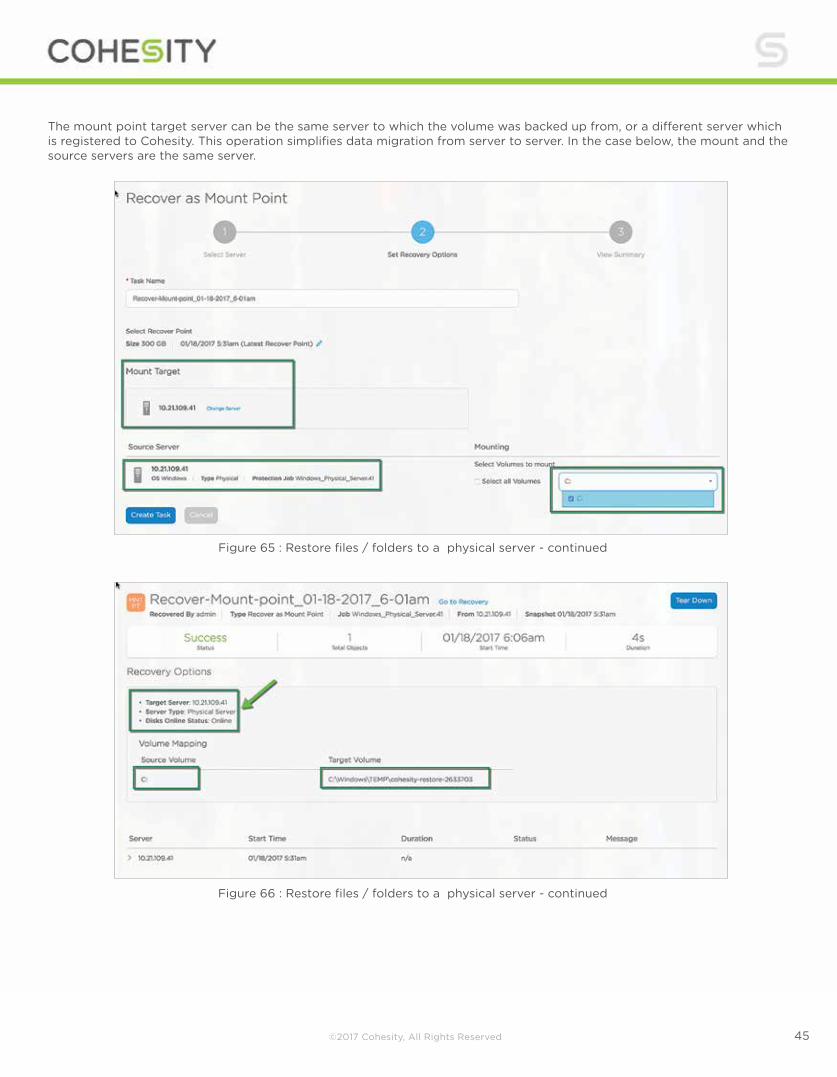
The mount point target server can be the same server to which the volume was backed up from, or a different server which is registered to Cohesity. This operation simplifies data migration from server to server. In the case below, the mount and the source servers are the same server.
Figure 65 : Restore files / folders to a physical server - continued
Figure 66 : Restore files / folders to a physical server - continued

©2017 Cohesity, All Rights Reserved 46
On the Windows server, browsing to the above directory provides the mounted volume and all the files contained in the volume.
Figure 67 : Restore files / folders to a physical server - continued
Figure 68 : Restore files / folders to a physical server - continued
©2017 Cohesity, All Rights Reserved 47
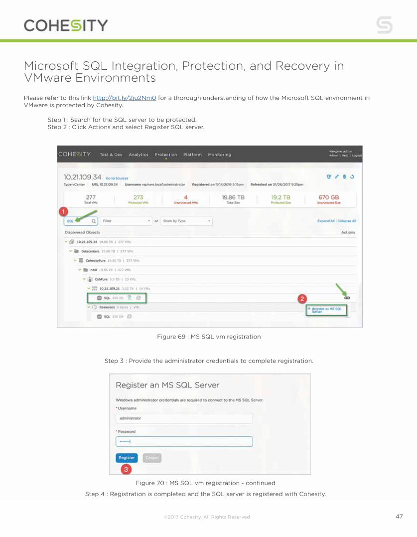
Microsoft SQL Integration, Protection, and Recovery in VMware Environments Please refer to this link http://bit.ly/2ju2Nm0 for a thorough understanding of how the Microsoft SQL environment in VMware is protected by Cohesity. Step 1 : Search for the SQL server to be protected. Step 2 : Click Actions and select Register SQL server.
Figure 69 : MS SQL vm registration
Step 3 : Provide the administrator credentials to complete registration.
Figure 70 : MS SQL vm registration - continued
Step 4 : Registration is completed and the SQL server is registered with Cohesity.

©2017 Cohesity, All Rights Reserved 48
Now that the VM has been registered as a MS SQL server, we are able to protect this server using the Cohesity MS SQL adapter. This adapter provides a point-in-time backup of the SQL server by backing up the database and the log backups.
Select MS SQL to use the Cohesity native adapter to create a data protection job for the View Composer SQL server that was registered above.
Once the server is selected, the next step is to associate it with the SQL Policy.
Figure 71 : MS SQL vm registration - continued
Figure 72 : Protection job for MS SQL VM

©2017 Cohesity, All Rights Reserved 49
In this case, the SQL database policy is set to protect the SQL server DB every 1 hour and, in addition, to capture logs every 15 mins. This combination of backups enables “point in time” restore.
Figure 73 : Protection job for MS SQL VM - continued
Figure 74 : Protection job for MS SQL VM - continued

©2017 Cohesity, All Rights Reserved 50
SQL RestoreIn this section, we will simulate the VMware Horizon Composer SQL database being accidently deleted and then restore it using the built-in SQL Restore function of the Cohesity appliance.
In the screen capture below we can see the Composer Database (named vc) in SQL Server Management Studio.
Figure 75 : Protection job for MS SQL VM - continued
Figure 76 : MS SQL VM databases in SQL Server Management Studio

©2017 Cohesity, All Rights Reserved 51
Next, it is deleted completely from the server.
Moving over to the Composer Server, we can see that the ODBC connection to the vc database now fails and that the Horizon Composer service is unable to start.
Figure 77,78 : MS SQL VM databases deleted accidentally
Figure 79 : MS SQL VM databases deleted accidentally - continued

©2017 Cohesity, All Rights Reserved 52
Figure 80 : MS SQL VM databases ODBC testing
Figure 81 : VMware Horizon services failing
Furthermore, we can see in the Horizon Connection server that the Composer server is offline, as the service is not able to start due to the database being deleted. Already problem desktops are appearing.

©2017 Cohesity, All Rights Reserved 53
Figure 82 : VMware View Composer service failure
Figure 83 : MS SQL VM databases restore
To recover from this traditionally major outage, we move to the Cohesity appliance and begin the MS SQL recovery operation.

©2017 Cohesity, All Rights Reserved 54
Figure 84 : MS SQL VM databases restore - continued
Figure 85 : MS SQL VM databases restore - continued
As this database was fully backed up every hour, with incremental logs backed up, we have the ability to restore the SQL database to any point over a very wide time interval. Since the database was not facing a corruption issue but instead accidental deletion in the example, we elected to recover it to as recent a time as possible.
Typing in the name of the vc database shows recovery options.
©2017 Cohesity, All Rights Reserved 55
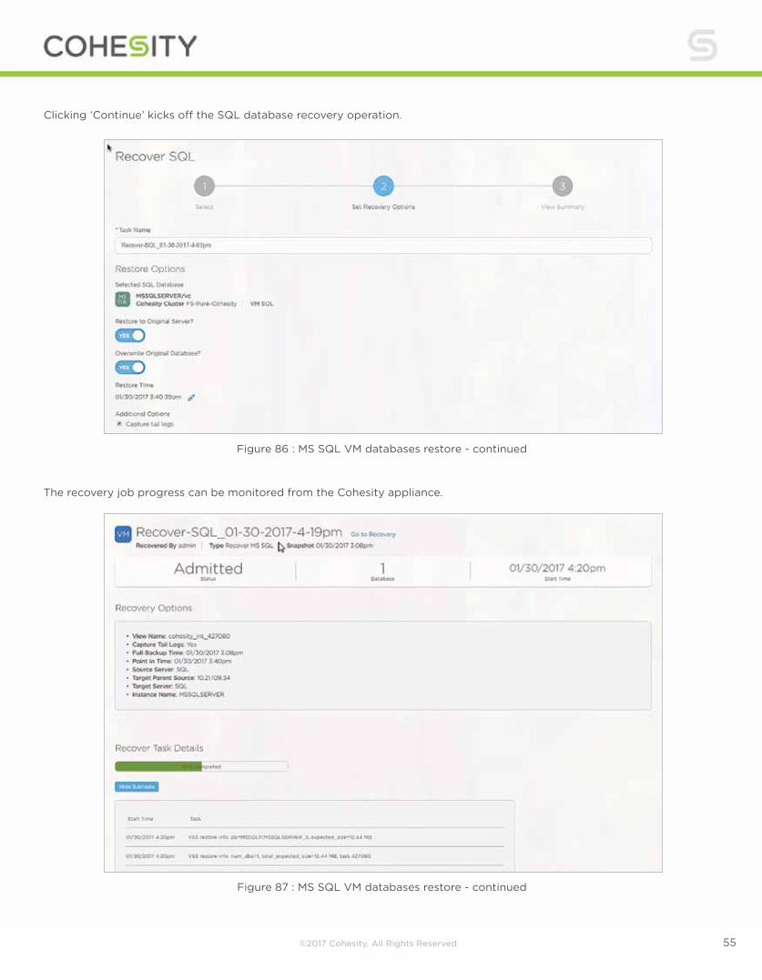
Figure 86 : MS SQL VM databases restore - continued
Figure 87 : MS SQL VM databases restore - continued
The recovery job progress can be monitored from the Cohesity appliance.
Clicking ‘Continue’ kicks off the SQL database recovery operation.
©2017 Cohesity, All Rights Reserved 56
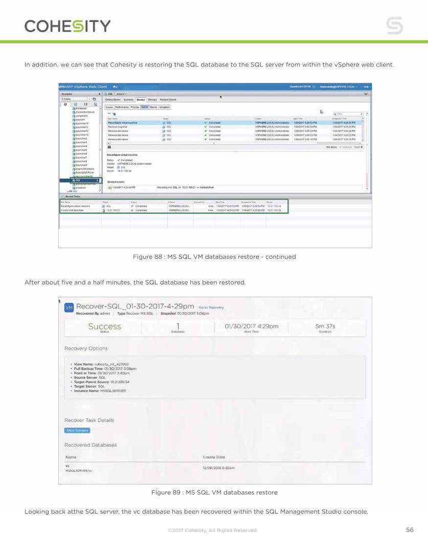
Figure 88 : MS SQL VM databases restore - continued
Figure 89 : MS SQL VM databases restore
After about five and a half minutes, the SQL database has been restored.
Looking back atthe SQL server, the vc database has been recovered within the SQL Management Studio console.
In addition, we can see that Cohesity is restoring the SQL database to the SQL server from within the vSphere web client.
©2017 Cohesity, All Rights Reserved 57
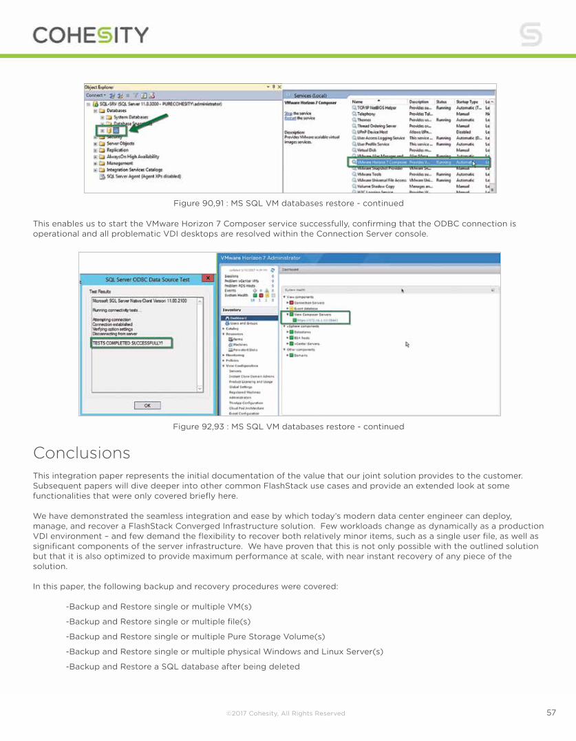
Figure 90,91 : MS SQL VM databases restore - continued
Figure 92,93 : MS SQL VM databases restore - continued
This enables us to start the VMware Horizon 7 Composer service successfully, confirming that the ODBC connection is operational and all problematic VDI desktops are resolved within the Connection Server console.
Conclusions This integration paper represents the initial documentation of the value that our joint solution provides to the customer. Subsequent papers will dive deeper into other common FlashStack use cases and provide an extended look at some functionalities that were only covered briefly here. We have demonstrated the seamless integration and ease by which today’s modern data center engineer can deploy, manage, and recover a FlashStack Converged Infrastructure solution. Few workloads change as dynamically as a production VDI environment – and few demand the flexibility to recover both relatively minor items, such as a single user file, as well as significant components of the server infrastructure. We have proven that this is not only possible with the outlined solution but that it is also optimized to provide maximum performance at scale, with near instant recovery of any piece of the solution. In this paper, the following backup and recovery procedures were covered: -Backup and Restore single or multiple VM(s)
-Backup and Restore single or multiple file(s)
-Backup and Restore single or multiple Pure Storage Volume(s)
-Backup and Restore single or multiple physical Windows and Linux Server(s)
-Backup and Restore a SQL database after being deleted

©2017 Cohesity, All Rights Reserved 5858.Cohesity, Inc. Address 451 El Camino Real, Santa Clara, CA 95050Email [email protected] www.cohesity.com ©2017 Cohesity. All Rights Reserved.
@cohesity
The logical setup and straightforwardness of use shown throughout provides a framework for an administrator to protect and recover the micro and the macro according to whatever SLA they are bound to. Since all administrative consoles are HTML5-based, all actions shown throughout this paper can be performed from any phone, tablet, or PC device that has an internet connection, VPN or LAN access to the data center, and a modern web browser. Pure Storage and Cohesity together deliver the best of both worlds: all-flash performance for your mission-critical applications and flash-driven consolidation of your secondary storage needs, including data protection with instant recovery and an agile method for repurposing data for test/dev and file services. Authors:
Kyle Grossmiller - Solutions Architect - Pure Storage
Damien Philip - Principal Solutions Architect - Cohesity Reviewers :
Mayur Dewaikar - Product Management - Pure Storage
Vivek Agarwal - Business Development - Cohesity
Ravi Venkat - Sr. DataCenter Architect - Pure Storage
Raymond Mar - Strategic Alliance Manager - Pure Storage