
Complementary Roles of Spark Range and Onboard Free …Army Research Laboratory Aberdeen Proving...
40
Complementary Roles of Spark Range and Onboard Free-Flight Measurements for Projectile Development by Bradford S. Davis, Bernard J. Guidos, and Thomas E. Harkins ARL-TR-4910 August 2009 Approved for public release; distribution is unlimited.
Transcript of Complementary Roles of Spark Range and Onboard Free …Army Research Laboratory Aberdeen Proving...
Complementary Roles of Spark Range and Onboard
Free-Flight Measurements for Projectile Development
by Bradford S. Davis, Bernard J. Guidos, and Thomas E. Harkins
ARL-TR-4910 August 2009
Approved for public release; distribution is unlimited.

NOTICES
Disclaimers The findings in this report are not to be construed as an official Department of the Army position unless so designated by other authorized documents. Citation of manufacturer’s or trade names does not constitute an official endorsement or approval of the use thereof. Destroy this report when it is no longer needed. Do not return it to the originator.
Army Research Laboratory Aberdeen Proving Ground, MD 21005-5066
ARL-TR-4910 August 2009
Complementary Roles of Spark Range and Onboard Free-Flight Measurements for Projectile Development
Bradford S. Davis, Bernard J. Guidos, and Thomas E. Harkins
Weapons and Materials Research Directorate, ARL Approved for public release; distribution is unlimited.
ii
REPORT DOCUMENTATION PAGE Form Approved OMB No. 0704-0188
Public reporting burden for this collection of information is estimated to average 1 hour per response, including the time for reviewing instructions, searching existing data sources, gathering and maintaining the data needed, and completing and reviewing the collection information. Send comments regarding this burden estimate or any other aspect of this collection of information, including suggestions for reducing the burden, to Department of Defense, Washington Headquarters Services, Directorate for Information Operations and Reports (0704-0188), 1215 Jefferson Davis Highway, Suite 1204, Arlington, VA 22202-4302. Respondents should be aware that notwithstanding any other provision of law, no person shall be subject to any penalty for failing to comply with a collection of information if it does not display a currently valid OMB control number. PLEASE DO NOT RETURN YOUR FORM TO THE ABOVE ADDRESS.
1. REPORT DATE (DD-MM-YYYY)
August 2009 2. REPORT TYPE
Final 3. DATES COVERED (From - To)
June 2008–May 2009 4. TITLE AND SUBTITLE
Complementary Roles of Spark Range and Onboard Free-Flight Measurements for Projectile Development
5a. CONTRACT NUMBER
5b. GRANT NUMBER
5c. PROGRAM ELEMENT NUMBER
6. AUTHOR(S)
Bradford S. Davis, Bernard J. Guidos, and Thomas E. Harkins 5d. PROJECT NUMBER
AH80 5e. TASK NUMBER
5f. WORK UNIT NUMBER
7. PERFORMING ORGANIZATION NAME(S) AND ADDRESS(ES)
U.S. Army Research Laboratory ATTN: RDRL-WMB-A Aberdeen Proving Ground, MD 21005-5066
8. PERFORMING ORGANIZATION REPORT NUMBER
ARL-TR-4910
9. SPONSORING/MONITORING AGENCY NAME(S) AND ADDRESS(ES)
10. SPONSOR/MONITOR’S ACRONYM(S)
11. SPONSOR/MONITOR'S REPORT NUMBER(S)
12. DISTRIBUTION/AVAILABILITY STATEMENT
Approved for public release; distribution is unlimited.
13. SUPPLEMENTARY NOTES
14. ABSTRACT
The U.S. Army Research Laboratory maintains capabilities for both external (ground-based, i.e., spark range) and onboard sensor system (telemetry- and recorder-based) methodologies for obtaining free-flight motion measurements of projectiles. These two methodologies were developed independently and until recently had been applied in projectile development programs without a thorough consideration of their synergistic interrelationship. Such a consideration is presented herein as a means for appropriating the benefits of each in a unified manner, thus making better use of available time and resources. A brief description of the two methodologies, their development histories, and their strengths and limitations is made. Complementary aspects are identified that can contribute to projectile development by accelerating progress, mitigating risks, and reducing costs. Future areas of instrumentation and technique advancement are cited that will positively impact the evolution of the complementary roles of ground- and telemetry-based methodologies. 15. SUBJECT TERMS
aerodynamics, telemetry, onboard measurements, spark range, ballistics
16. SECURITY CLASSIFICATION OF: 17. LIMITATION OF ABSTRACT
UU
18. NUMBER OF PAGES
40
19a. NAME OF RESPONSIBLE PERSON
Bradford S. Davis a. REPORT
Unclassified b. ABSTRACT
Unclassified c. THIS PAGE
Unclassified 19b. TELEPHONE NUMBER (Include area code)
410-306-0738 Standard Form 298 (Rev. 8/98)
Prescribed by ANSI Std. Z39.18
iii
Contents
List of Figures iv
1. Introduction 1
2. Ground-Based Free-Flight Measurements 2
3. Onboard Free-Flight Measurements 7
4. Comparison of Spark Range and Telemetry Methodologies 10
4.1 Aerodynamic Coefficients Results 10
4.2 MET Conditions 12
4.3 Flight Hardware Preparation 12
4.4 Range Preparation and Coordination 14
4.5 Test Execution 15
4.6 Data Reduction and Analysis 17
4.7 Other Capabilities and Tradeoffs 17
5. Complementary Roles 19
6. Conclusion 20
7. References 23
Distribution List 27

iv
List of Figures
Figure 1. ARL TM firing conducted beside the spark range facility. .............................................2
Figure 2. Yaw cards from finned long-rod projectile flight experiments. ......................................3
Figure 3. Large-caliber firing through TEF spark range from outside gun mount. ........................4
Figure 4. Indoor view of AEF spark range. ....................................................................................4
Figure 5. Indoor view of TEF spark range. .....................................................................................5
Figure 6. Positive film shadowgraphs from AEF (left) and TEF (right) spark ranges. ..................6
Figure 7. Projectile state measurement systems. ............................................................................9
Figure 8. Zero-yaw drag (axial force) and pitching moment coefficients. ...................................11
Figure 9. Pitch damping and Magnus moment coefficients. ........................................................11
Figure 10. Small-, medium-, and large-caliber MOI measurement devices. ................................13
Figure 11. Environmental qualification and sensor calibration equipment. .................................14
Figure 12. Damaged spark generator and camera in spark range. ................................................16
Figure 13. NASA CEV model fired from a 120-mm gun. ............................................................20
Figure 14. Caliber 5.56-mm projectile. .........................................................................................22
1
1. Introduction
The modern era of exterior ballistics began in the early 20th century and was marked by developmental progress in two areas: (1) experimental methods for observing the dynamic states of projectiles in free flight and (2) analytical aerodynamic force and moment formulation of the laws of motion for describing the flight of symmetric projectiles progressively yielding the equations used today. Projectile free-flight motion measurements and accompanying analysis thus became an integral component of weapon system development. Whyte et al. (1973) wrote, “In free flight studies, the main task is to determine from observations of a missile’s motion the values of the aerodynamic coefficients appearing in the differential equations describing that motion,” and that task has remained unchanged throughout the modern era. This quote preceded the onset of the modern microelectronics and personal computer revolution. In the interim, improvements in existing measurement methodologies, development of new measurement methodologies, and availability of high-powered computer analyses have dramatically enhanced the accuracy and efficacy of exterior ballistics.
Prior to the microelectronics revolution of the last few decades, free-flight motion measurements of gun-launched projectiles were almost exclusively made using devices external to the projectiles. Since then, ever smaller and more capable sensors, processors, transmitters, and associated onboard components useful for obtaining state measurements have become available. Onboard free-flight measurement techniques are used to obtain continuous in-bore and in-flight measurements of phenomena resulting from the complex projectile dynamics of launch and flight.
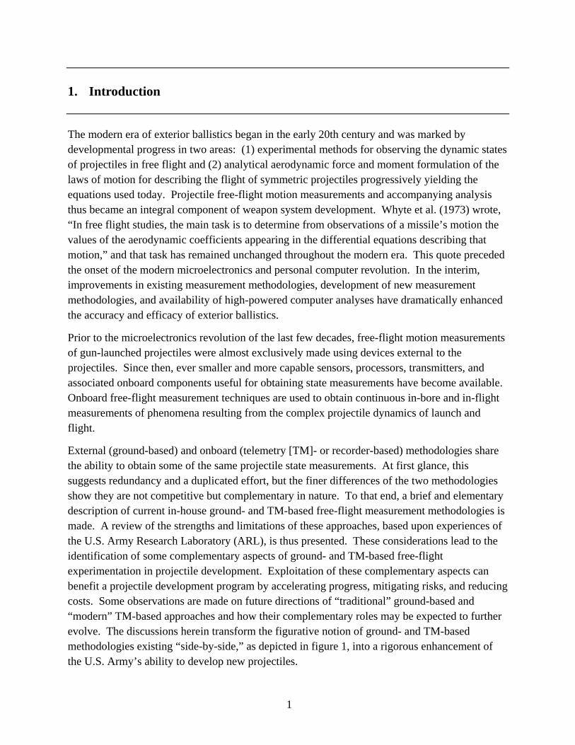
External (ground-based) and onboard (telemetry [TM]- or recorder-based) methodologies share the ability to obtain some of the same projectile state measurements. At first glance, this suggests redundancy and a duplicated effort, but the finer differences of the two methodologies show they are not competitive but complementary in nature. To that end, a brief and elementary description of current in-house ground- and TM-based free-flight measurement methodologies is made. A review of the strengths and limitations of these approaches, based upon experiences of the U.S. Army Research Laboratory (ARL), is thus presented. These considerations lead to the identification of some complementary aspects of ground- and TM-based free-flight experimentation in projectile development. Exploitation of these complementary aspects can benefit a projectile development program by accelerating progress, mitigating risks, and reducing costs. Some observations are made on future directions of “traditional” ground-based and “modern” TM-based approaches and how their complementary roles may be expected to further evolve. The discussions herein transform the figurative notion of ground- and TM-based methodologies existing “side-by-side,” as depicted in figure 1, into a rigorous enhancement of the U.S. Army’s ability to develop new projectiles.
2
Figure 1. ARL TM firing conducted beside the spark range facility.
2. Ground-Based Free-Flight Measurements
The discussion herein is limited to methodologies that entail actual gun firings. Wind tunnel measurements and computational fluid dynamics predictions are two other methodologies for characterizing projectile aerodynamics, and both are valuable tools used in projectile development programs.
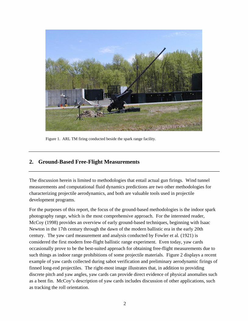
For the purposes of this report, the focus of the ground-based methodologies is the indoor spark photography range, which is the most comprehensive approach. For the interested reader, McCoy (1998) provides an overview of early ground-based techniques, beginning with Isaac Newton in the 17th century through the dawn of the modern ballistic era in the early 20th century. The yaw card measurement and analysis conducted by Fowler et al. (1921) is considered the first modern free-flight ballistic range experiment. Even today, yaw cards occasionally prove to be the best-suited approach for obtaining free-flight measurements due to such things as indoor range prohibitions of some projectile materials. Figure 2 displays a recent example of yaw cards collected during sabot verification and preliminary aerodynamic firings of finned long-rod projectiles. The right-most image illustrates that, in addition to providing discrete pitch and yaw angles, yaw cards can provide direct evidence of physical anomalies such as a bent fin. McCoy’s description of yaw cards includes discussion of other applications, such as tracking the roll orientation.
3
Bent
Figure 2. Yaw cards from finned long-rod projectile flight experiments.
The first spark range used for projectile aerodynamics determination was completed during World War II at the U.S. Army Ballistics Research Laboratory (BRL) at Aberdeen Proving Ground, MD. The earliest descriptions and results are by Braun et al. (1943) and Charters and Thomas (1945). The first comparison of the accuracy of flight parameters obtained from yaw card and spark range techniques was by Karpov (1953). This range was designated a National Historic Mechanical Engineering Landmark by the American Society of Mechanical Engineers in 1982 (see Schmidt, 1983). A detailed account of the trials and errors in the initial development of this range is a central focus in the paper by Charters (1995).
The Aerodynamics Branch of ARL currently maintains two indoor spark photography facilities, both at Aberdeen Proving Ground. The first is the Aerodynamics Experimental Facility (AEF), the modernized incarnation of the original spark range described in the aforementioned references. The AEF is suitable for projectiles of the smallest caliber, such as 5.56-mm ammunition, to projectiles of medium caliber, such as 40-mm grenades. All firings through the AEF are conducted from an adjacent indoor blast chamber.
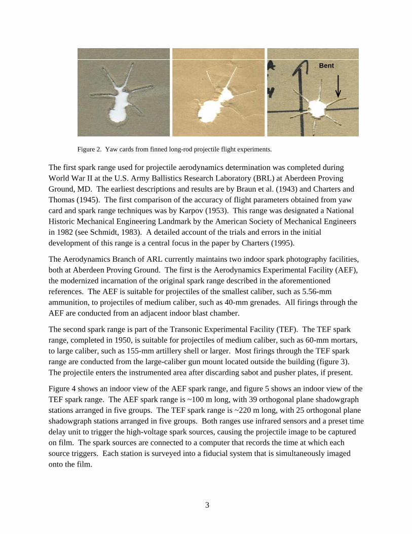
The second spark range is part of the Transonic Experimental Facility (TEF). The TEF spark range, completed in 1950, is suitable for projectiles of medium caliber, such as 60-mm mortars, to large caliber, such as 155-mm artillery shell or larger. Most firings through the TEF spark range are conducted from the large-caliber gun mount located outside the building (figure 3). The projectile enters the instrumented area after discarding sabot and pusher plates, if present.
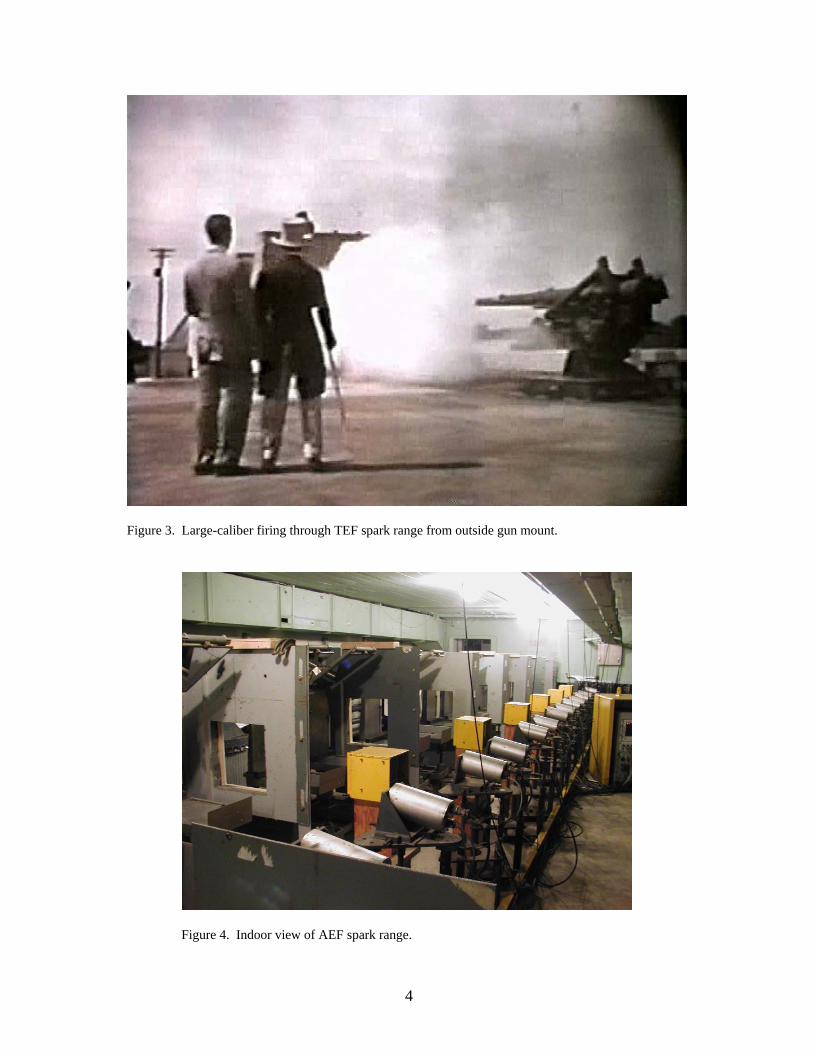
Figure 4 shows an indoor view of the AEF spark range, and figure 5 shows an indoor view of the TEF spark range. The AEF spark range is ~100 m long, with 39 orthogonal plane shadowgraph stations arranged in five groups. The TEF spark range is ~220 m long, with 25 orthogonal plane shadowgraph stations arranged in five groups. Both ranges use infrared sensors and a preset time delay unit to trigger the high-voltage spark sources, causing the projectile image to be captured on film. The spark sources are connected to a computer that records the time at which each source triggers. Each station is surveyed into a fiducial system that is simultaneously imaged onto the film.
4
Figure 3. Large-caliber firing through TEF spark range from outside gun mount.
Figure 4. Indoor view of AEF spark range.

5
Figure 5. Indoor view of TEF spark range.
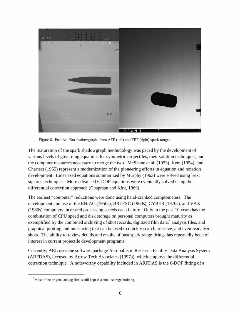
Examples of positive film images from both ranges are shown in figure 6. The AEF film, 11 × 14 in, is a direct-exposure image of the shadow formed by the projectile blocking the light source. The shadow in this image was produced by a 40-mm grenade. The TEF film, 4 × 5 in, includes two images on the screen, the blurred image being the projectile and the focused image being the shadow of a 155-mm artillery shell.
The spark shadowgraphs provide detailed flow field visualization. Fluid dynamic structures visible in spark shadowgraphs include shock waves, compression waves, expansion waves, boundary layer transition and growth, separated flow regions, free shear layers, and vortices. Examples of the visual high fidelity of spark shadowgraphs can be found in McCoy (1998) and Van Dyke (1982).
Each piece of negative image film is manually read on a precision light table to produce the measured spatial coordinates (range, deflection, altitude) and angular orientation (pitch, yaw, and if a spin pin is used, roll angle) relative to an earth-fixed range coordinate system, all as a function of the spark time. The discrete position and angular orientation values are used to fit linear and 6-degree-of-freedom (6-DOF) models of projectile motion that allow characterization of the aerodynamics and flight dynamics.
6
Figure 6. Positive film shadowgraphs from AEF (left) and TEF (right) spark ranges.
The maturation of the spark shadowgraph methodology was paced by the development of various levels of governing equations for symmetric projectiles, their solution techniques, and the computer resources necessary to merge the two. McShane et al. (1953), Kent (1954), and Charters (1955) represent a modernization of the pioneering efforts in equation and notation development. Linearized equations summarized by Murphy (1963) were solved using least squares techniques. More advanced 6-DOF equations were eventually solved using the differential correction approach (Chapman and Kirk, 1969).
The earliest “computer” reductions were done using hand-cranked comptometers. The development and use of the ENIAC (1950s), BRLESC (1960s), CYBER (1970s), and VAX (1980s) computers increased processing speeds each in turn. Only in the past 10 years has the combination of CPU speed and disk storage on personal computers brought maturity as exemplified by the combined archiving of shot records, digitized film data,* analysis files, and graphical plotting and interfacing that can be used to quickly search, retrieve, and even reanalyze shots. The ability to review details and results of past spark range firings has repeatedly been of interest in current projectile development programs.
Currently, ARL uses the software package Aeroballistic Research Facility Data Analysis System (ARFDAS), licensed by Arrow Tech Associates (1997a), which employs the differential correction technique. A noteworthy capability included in ARFDAS is the 6-DOF fitting of a
*Most of the original analog film is still kept in a small storage building.
7
single set of aerodynamic coefficients to multiple-shot groups. This capability increases the accuracy of the fitted aerodynamic coefficients, especially those required for computation of nonlinear behavior with respect to angle of attack.
3. Onboard Free-Flight Measurements
Radar, though fundamentally ground-based, is a necessary component in TM-based methodologies that requires aerodynamic and flight parameters to be expressed as a function of Mach number. Radar has been extensively used for projectile development for several decades. Fixed-head radar provides velocity history, from which total aerodynamic drag can be obtained. Tracking radar additionally provides lateral position with enough fidelity to construct a trajectory arc. Qualitative aerodynamic stability assessments can be obtained from radar, such as the correlation between increases in aerodynamic drag and mean angle of attack. Radar can often be used to obtain roll rate if a proper geometric feature is inherent in the projectile design or incorporated in the base of the projectile to provide a polarized or attenuating radar reflection.
The earliest description ARL has found of an experiment employing onboard systems to obtain estimates of free-flight projectile dynamics is Gotlieb et al. (1948). In this experiment, a projectile was equipped with a radio transmitter. The variations in signal strength at a ground receiving station were used to approximate the projectile’s yawing behavior. The recorded analog strip charts were manually examined to obtain the time history of signal fluctuations. As there were inaccurate calibration data for the yaw angle as a function of signal strength, the estimated yawing behavior was more of a qualitative than a quantitative result.
Ten years later, instrumented flight experiments conducted to investigate aerodynamics of high-drag, low-lift bodies were reported by the Langley Aeronautical Laboratory (Coltrane, 1958). Cylindrical bodies 8 inches in diameter were equipped with a six-channel TM system transmitting data from six accelerometers that were recorded for subsequent analyses. Variations in received signal strength were also used to estimate flight body roll rates.
ARL and its predecessor, BRL, have developed and employed custom TM systems to obtain data from onboard sensors for the measurement of in-flight projectile states for the past 35 years. The first such system, a yawsonde, employed optical detectors on a rotating projectile. The TM system transmitted the detector’s output, which was recorded and used to identify the times at which the sun was within the detector’s fields of view. Although not the first to use solar sensors, Clay (1973) and Mermagen and Clay (1974) were responsible for advancements that made yawsondes into precision angular measurement systems.
8
Mechanical devices, inertial sensors, and other types of transducers have long been available, but using this class of devices on board gun-launched ordnance projectiles was not generally practicable until the last few decades. Hardware meeting the criteria of size, weight, cost, performance, and survivability in the harsh projectile launch environment was not then available. With the microelectronics revolution, the commercial sector began producing smaller and more capable components for industrial and consumer use. ARL is at the forefront of efforts to incorporate newly available off-the-shelf components for obtaining onboard projectile state measurements. For example, small and rugged accelerometers used for airbag deployment in automobiles are also usable for projectile acceleration measurements.
The Aeroballistic Diagnostic Fuze (DFuze) is a patented instrumentation system (Hepner et al., 2002) developed by the Advanced Munitions Concepts Branch of ARL. DFuze is a technological advancement of the yawsonde, packaged in a NATO-compatible artillery fuze shape. It contains high g-qualified miniature sensors, microelectronics, onboard data acquisition, a power supply, and TM components necessary to obtain and transmit the desired measurements. The standard DFuze model circa 2003 sensor suite includes three orthogonal axes of translational accelerometers, three orthogonal axes of vector magnetometers, three orthogonal axes of angular rate sensors, a yawsonde using four optical sensors, a constellation of four accelerometers configured and combined to yield a centripetal acceleration measurement, and a temperature sensor.
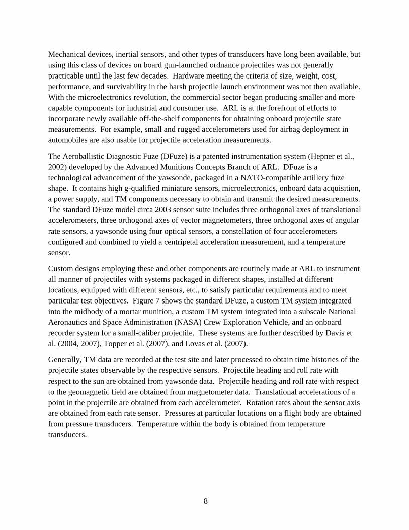
Custom designs employing these and other components are routinely made at ARL to instrument all manner of projectiles with systems packaged in different shapes, installed at different locations, equipped with different sensors, etc., to satisfy particular requirements and to meet particular test objectives. Figure 7 shows the standard DFuze, a custom TM system integrated into the midbody of a mortar munition, a custom TM system integrated into a subscale National Aeronautics and Space Administration (NASA) Crew Exploration Vehicle, and an onboard recorder system for a small-caliber projectile. These systems are further described by Davis et al. (2004, 2007), Topper et al. (2007), and Lovas et al. (2007).
Generally, TM data are recorded at the test site and later processed to obtain time histories of the projectile states observable by the respective sensors. Projectile heading and roll rate with respect to the sun are obtained from yawsonde data. Projectile heading and roll rate with respect to the geomagnetic field are obtained from magnetometer data. Translational accelerations of a point in the projectile are obtained from each accelerometer. Rotation rates about the sensor axis are obtained from each rate sensor. Pressures at particular locations on a flight body are obtained from pressure transducers. Temperature within the body is obtained from temperature transducers.
9
(a) DFuze (b) Midbody TM
(c) Apollo model TM (d) Sensors and recorder
Figure 7. Projectile state measurement systems.
Typical range instrumentation consists of high-speed video cameras, tracking radars, and a TM ground station. The TM ground station usually employs several receivers tied to TM receiving antennas at different locations and with different pointing orientations to ensure complete coverage of the trajectory and to add redundancy. Surface meteorological (MET) stations near the gun site record local temperature, humidity, and winds, and MET balloons record temperature, humidity, and winds downrange. All measurement data are referenced to Inter-Range Instrumentation Group (IRIG) time.
As these new onboard data sources became available, work was initiated to develop tools to use these data for aerodynamic coefficient estimation. In an early effort employing TM data, yawsonde measurements were combined with ground radar velocity measurements and processed with Arrow Tech Associates’ aerodynamic prediction codes to determine stability characteristics and to obtain certain aerodynamic force and moment coefficients (Whyte and Mermagen, 1973). Next, ARL and Arrow Tech successfully applied these techniques to a 2.75-in rocket to determine drag, static moment, and roll moment coefficients as described by Brown et al. (1997) and Hathaway et al. (2000). By this time, the onboard instrumentation included an array of sensors that, combined with novel sensor data processing techniques, allowed the body forces and body rates to be calculated accurately from launch through impact.
10
Recently, ARL and Arrow Tech developed a custom software program to use the TM data and other information to calculate the aerodynamic coefficients of a projectile. The program, Extending Telemetry Reduction to Aerodynamic Coefficients and Trajectory Reconstruction (EXTRACTR), described by Davis et al. (2005), imports the sensor data, MET data, radar data, and projectile physical properties to process, through an iterative algorithm, a solution for the aerodynamic coefficients that would have caused the measured flight response. The code attempts to fit the measured translational and rotational sensor data to the 6-DOF equations of motion by using the same general differential corrections method used within the spark range reduction software ARFDAS that was introduced earlier in the report.
EXTRACTR input data include the projectile characteristics (e.g., physicals, initial guess at aerodynamics), launch conditions (e.g., quadrant elevation, muzzle velocity, firing time, test location, sun position), MET along the trajectory, and processed radar and TM data. These data are interpolated onto a common time base using the respective IRIG time stamps.
Separate modules are built into EXTRACTR, implementing differential corrections for equations of motion of various levels of complexity and fidelity. Typically these modules are employed sequentially where each successive model includes more degrees of freedom, estimates more parameters, and requires more observational data. Uncoupling the motion prior to the highest-fidelity model allows investigation of individual phenomena (such as drag) before considering the complicated interaction of all phenomena. Parameter estimates at each level provide initial estimates for successive analyses. Refinement continues until the process achieves a minimum residual sum of squares. At this point, the estimation process can only be improved with a more detailed model or a set of observations with smaller measurement error.
Capabilities for TM-based free-flight measurement are being developed elsewhere. Abate and Klomfass (2004) provided a detailed analysis on how AeroSolve could be implemented using only modeled data but could not evaluate the approach with experimental data at the time of the report because it was not available. Toledo and Recchia (2004) used DFuze data and the TELA code to determine the aerodynamics of the Army’s Mid-Range Munition that is currently under development.
4. Comparison of Spark Range and Telemetry Methodologies
4.1 Aerodynamic Coefficients Results
In 2003, a firing program was conducted by ARL and Arrow Tech to demonstrate and further develop the EXTRACTR software. A controlled experiment was designed to obtain an in-flight data set using the DFuze instrumentation system for a projectile with well-known aerodynamics. The 155-mm M483A1 artillery projectile was selected as the control projectile because it had
11
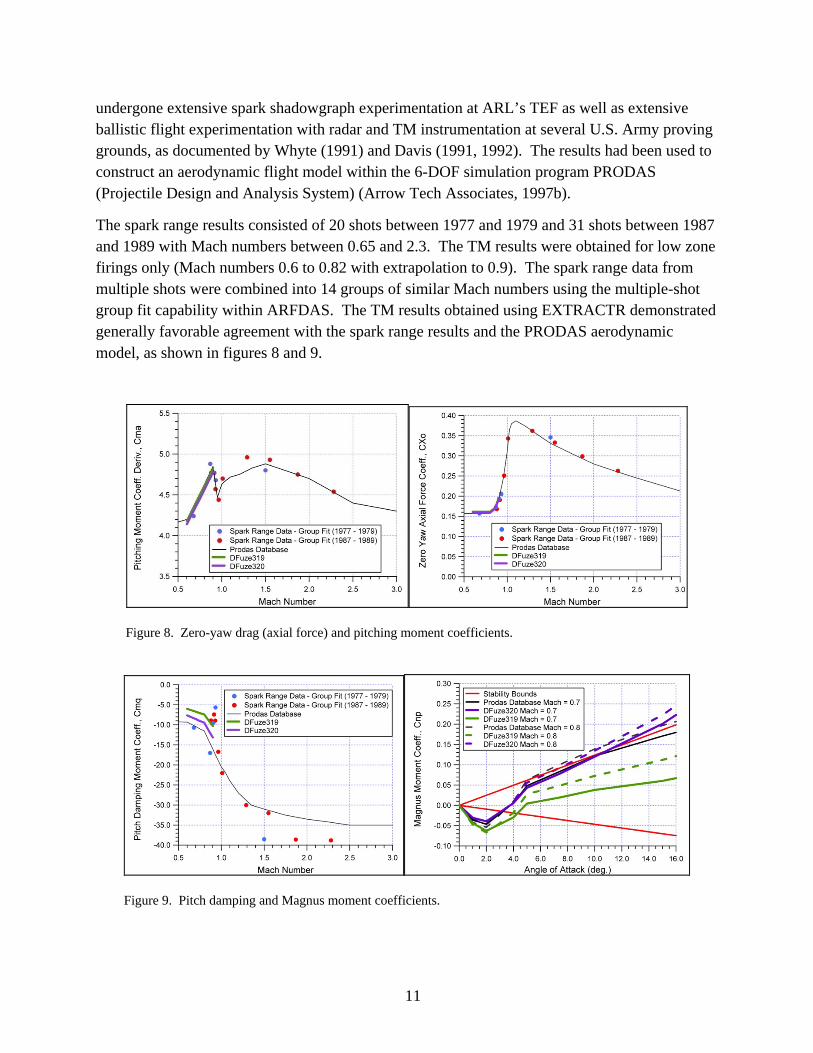
undergone extensive spark shadowgraph experimentation at ARL’s TEF as well as extensive ballistic flight experimentation with radar and TM instrumentation at several U.S. Army proving grounds, as documented by Whyte (1991) and Davis (1991, 1992). The results had been used to construct an aerodynamic flight model within the 6-DOF simulation program PRODAS (Projectile Design and Analysis System) (Arrow Tech Associates, 1997b).
The spark range results consisted of 20 shots between 1977 and 1979 and 31 shots between 1987 and 1989 with Mach numbers between 0.65 and 2.3. The TM results were obtained for low zone firings only (Mach numbers 0.6 to 0.82 with extrapolation to 0.9). The spark range data from multiple shots were combined into 14 groups of similar Mach numbers using the multiple-shot group fit capability within ARFDAS. The TM results obtained using EXTRACTR demonstrated generally favorable agreement with the spark range results and the PRODAS aerodynamic model, as shown in figures 8 and 9.
Figure 8. Zero-yaw drag (axial force) and pitching moment coefficients.
Figure 9. Pitch damping and Magnus moment coefficients.
12
Accuracy estimation is not addressed here but is discussed by Davis et al. (2005). The differential correction technique used in both ARFDAS and EXTRACTR generates probable errors in terms of sensitivity coefficients, which are partial derivatives of fitted parameters with respect to the total error of the fit (Chapman and Kirk, 1969; Whyte and Hathaway, 1996). Spark range accuracy estimation is discussed by Murphy (1954, 1963), Chapman et al. (1970), and McCoy (1998). Though TM individual discrete measurements thus obtained are typically less accurate than those from spark range measurements, processing the much greater quantities of data using statistical techniques improves measurement fidelity.
4.2 MET Conditions
MET data are required to accurately determine the aerodynamic coefficients when fitting the equations of motion to the observed motion. The spark range is, within certain limits, a controlled environment in which MET conditions (temperature, pressure, humidity, and wind) are well-determined and fairly constant throughout. Automated instrumentation continuously measures MET conditions inside the building, and the conditions are recorded with the other data. Wind is never an issue for spark range firings, and firings are seldom postponed except in the worst of weather conditions.
For TM firings, significant MET variations routinely occur not only as functions of location and season, but also within the spatial and temporal extent of an individual trajectory. Ground-level MET stations and/or balloons are used to measure the local MET conditions, but applicability of the MET data is partially a function of how close in time and distance the measurements are gathered relative to the firing. Obtaining MET data adequate for aerodynamic analysis requires coordinating with local MET personnel for the release of balloons at strategic times and locations. Oftentimes, the measurements are supplemented with computer models prepared using local measurement and regional models to better approximate the MET along test flight trajectories. Postponement of TM firings can occur due to adverse weather or inadequate lighting, but the frequency is location dependent.
4.3 Flight Hardware Preparation
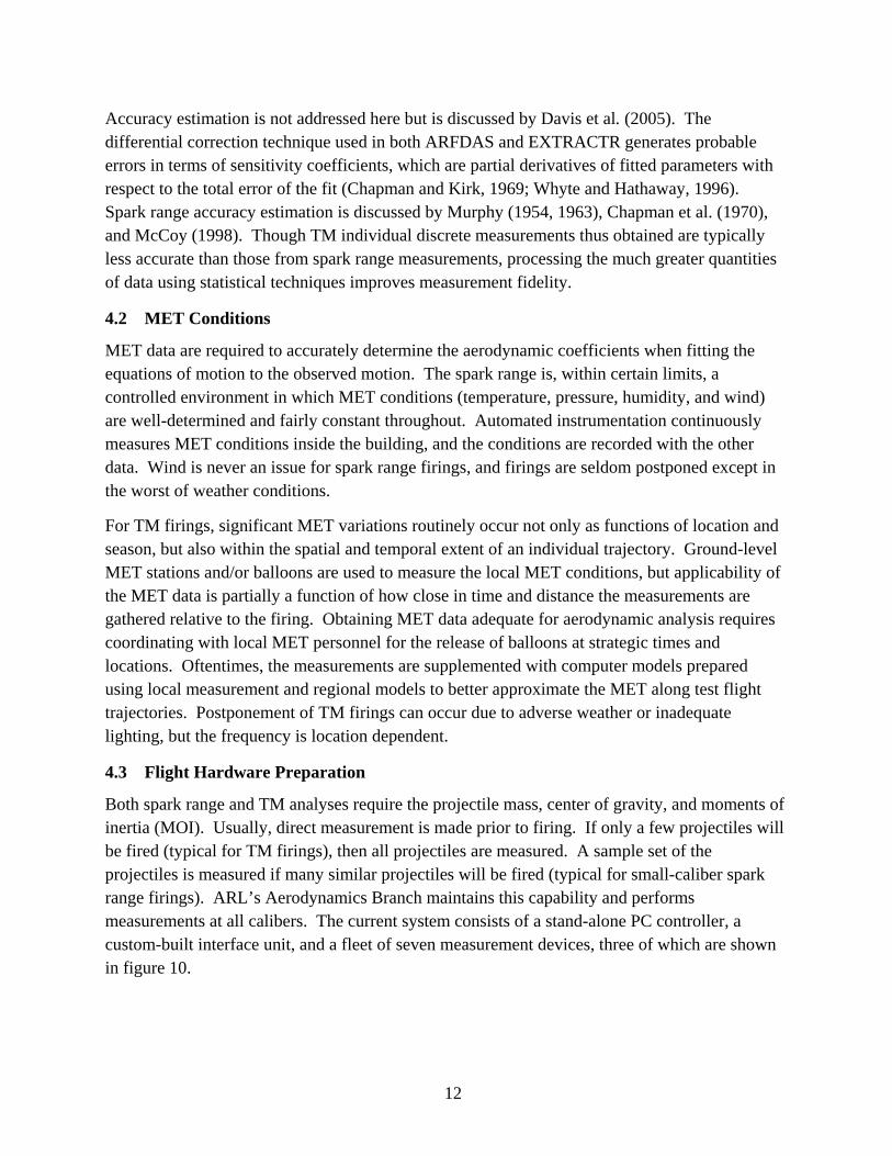
Both spark range and TM analyses require the projectile mass, center of gravity, and moments of inertia (MOI). Usually, direct measurement is made prior to firing. If only a few projectiles will be fired (typical for TM firings), then all projectiles are measured. A sample set of the projectiles is measured if many similar projectiles will be fired (typical for small-caliber spark range firings). ARL’s Aerodynamics Branch maintains this capability and performs measurements at all calibers. The current system consists of a stand-alone PC controller, a custom-built interface unit, and a fleet of seven measurement devices, three of which are shown in figure 10.
13
Figure 10. Small-, medium-, and large-caliber MOI measurement devices.
For spark range firings, projectile hardware preparation is minimal, typically consisting of the manufacture and shipping of inert versions of the tactical configurations. On some occasions, the round may be modified slightly to satisfy particular test requirements (e.g., adding spin pins or spin plugs to determine the roll orientation or spin rate).
For TM firings, projectile hardware preparation is focused on the onboard electronic components and can be significant. Generally, components need to be installed within the flight body without affecting the aerodynamic characteristics. In applications such as the DFuze, TM assemblies can be complete systems used as replacements for removable portions of a projectile with due consideration for matching that portion’s physical and mass properties. In such cases, the preparation requirements are confined to satisfying the survivability requirements of the expected operational environment. In other instances, modularity is not possible, so custom design, fabrication, and installation of flight instrumentation can impact virtually every aspect of projectile design and require participation by members of the projectile development team from many disciplines.
Some examples of general rules regarding custom instrumentation systems are (1) the smaller the projectile, the more difficult it is to meet physical requirements, (2) the harsher the environment, the greater the likelihood of requiring additional potting or reinforcements to achieve instrument survivability, and (3) for sufficiently long test projectile trajectories, the TM system may require a larger, higher-wattage transmitter or extra batteries that may take up space.
For TM-based instrumentation, onboard sensors usually require shock testing and calibration prior to the flight test. Calibration is the process of accurately determining sensor locations, orientations, scale factors, and biases. Typical calibration procedures involve exciting the various sensors with known stimuli using suitable laboratory equipment, recording the sensor output, and analyzing the data to obtain calibration parameters. Depending on the application, calibration can involve the design and fabrication of suitable fixtures and/or the development of suitable methods. Calibrating standard configurations can require a few days or more;

14
calibrating novel configurations can take weeks. Figure 11 shows some examples of environmental qualification and calibration equipment.
(a) Shock table (b) Temperature/humidity chamber
(c) Helmholtz coil (d) Centrifuge (e) Light table
Figure 11. Environmental qualification and sensor calibration equipment.
4.4 Range Preparation and Coordination
Spark range and TM firings require comparable weapon and charge component expertise, preparations, and management infrastructure. Both require comparable levels of interior ballistic charge establishment and/or structural launch integrity considerations, whether via simulation or firings. Both also require comparable efforts to implement and execute standard operating procedures that protect personnel and equipment. Shadowgraphs have additional safety and disposal issues associated with film-developing chemicals.
Safety considerations for TM firings must additionally account for the presence of potentially high-powered emitters and wires and cables from the instrumentation. The elevated trajectories of TM firings often have impact safety fans that can extend to other facilities or open access areas only restricted during firings. At some facilities, firings can be delayed because of intruders within the safety fan. Large-caliber spark range firings are not always exempt from this; in some cases, possible ricochet from the ground or terminating sand pile must be accounted for in preflight safety analyses.
15
Personnel required at the firing site differ significantly for the execution of spark range and TM tests. In a typical spark range test, four to six technicians and one or two engineers execute the shot-by-shot planning, gun firing, range operations, data collection, and preliminary data evaluation.
Personnel required for TM firings typically include a dozen or more technicians for gun and range operations, high-speed photography expertise, radar tracking and processing, test site communications, and TM acquisition. Additional personnel at other locations are sometimes required for TM and radar coverage and impact spotting. Engineering support is more extensive than spark range firings because of the engineering aspects of onboard hardware and postshot data review.
Data acquisition instrumentation used in both spark range and TM firings requires periodic calibration. Spark range firings require maintenance of screens, survey markers and wires, electronic trigger units, delay generators, infrared detectors, spark sources, cameras, and film development units. Surveying fiducial markers in the spark range is less critical than in the past because of the multiple-shot dynamic calibration capability available in the ARFDAS software (Chapman et al., 1970).
The film and development chemicals used to produce spark shadowgraphs add to the logistics of preparation in terms of acquisition, shelf life, restocking, and manual labor at all stages of the program.
Spark range firings require verification of launch integrity to avoid damage to instrumentation (see figure 12) and to optimize the trajectory arc to remain within the image-viewing windows. Particular attention must be paid when using a yaw-induction technique at the muzzle, which can impart a sizable trajectory deflection. TM firings, typically elevated, can be conducted with less risk of damage to instrumentation positioned in the field through the use of armor-like shielding and less constrained spatial considerations.
TM firings require consideration of the launch site line-of-sight availability and multipath sensitivity (i.e., angle of trajectory relative to measured field). Multiple radar and TM antennas are often arranged in different locations to provide complete trajectory coverage. TM firings that include optical detectors are currently restricted to times when the sun is observable along the expected trajectory.
4.5 Test Execution
The shot cadence of spark range and TM firings is comparable. Instrument verification firings are typically conducted in both methodologies to ensure general functionality of triggers, timings, instrument settings, etc. When preparations are finally made for the first full-up data acquisition round, the goal is to obtain success for that round and then worry about efficient shot cadence later. Early in a firing program, one to three rounds per day can be expected, depending on circumstances that are often unforeseeable. Late in a firing program, several additional rounds per day can be expected, after problems have been solved and routines have been established.
16
Figure 12. Damaged spark generator and camera in spark range.
For spark range firings, the shot cadence is currently limited by the time required to load the unexposed film in the darkened range, followed by its collection, subsequent development, and initial onsite review.
For TM firings, sensor data are recorded in real time, and subsequent shots can be fired as rapidly as safe gun operations permit. In practice, though, acquired data is typically examined for integrity before the next round is fired. ARL-developed sensor data visualization and processing software are routinely used to provide qualitative and semi-quantitative information regarding the flight performance within 10 to 30 min, a process known as “quick look.”
The quantity and nature of the collected data from firings are very different between the two methods. For spark range firings, test data are limited to the number of operational stations. Data products collected and stored include the photos from each station and the digital record of event times and range MET. The total disk usage is a few hundred kilobytes per shot.
For TM firings, test data typically include high-speed photos (visible and/or x-ray) near the muzzle, tracking video, range MET information, digital files from one or more radars, and digital files from multiple (typically three or four) independent TM receivers. TM file sizes are a function of the data rates and the projectile time of flight. The most commonly used transmitter at ARL has a rate of ~3.3 Mb/s. File sizes from each receiver are typically on the order of tens of megabytes for flight times under a minute. For long-range flights of artillery and rocket-assisted projectiles, gigabyte file sizes are not unusual.
17
4.6 Data Reduction and Analysis
As outlined earlier, both ARFDAS and EXTRACTR are designed to obtain values for aerodynamic coefficients necessary to generate a predicted trajectory with the 6-DOF equations that reproduce the experimentally obtained free-flight motion. In both cases, “raw” test data need to be generated or processed to obtain the respective ARFDAS and EXTRACTR input parameters and data streams.
ARFDAS inputs are derived from photographs at surveyed orthogonal stations. The timing information is digitally recorded during the flight test, but the position and orientation values are obtained by examining the individual photographs. Included on each photo are both the projectile and the fiducial marks in the respective horizontal or vertical image plane. Manual derivation methods with rulers and protractors have been replaced with automated photo-reading equipment that has improved measurement accuracy and greatly accelerated and economized data reduction. Once a rhythm is established, each piece of film can be manually processed in about 1 min. One shot can require 30 to 90 min to read all pieces of film, depending on the number of stations and particular aspects of the geometry. A person who is willing and able can be expected to read film accurately for about 4 to 5 h/day. ARFDAS-digitized film data is a few kilobytes per shot.
ARFDAS final output consists of a collection of computer files that contain individual shot analysis results, graphical parameters, and tabular summaries, totaling a few hundred kilobytes per shot. ARFDAS analysis of a set of shots can require hours, days, or weeks, depending on the number of shots and the complexity of the flight model. Organizing the analysis into presentation form requires additional hours, days, or weeks.
EXTRACTR uses time, radial velocity (from radar), orientation (relative to the sun and/or geomagnetic field), and body-fixed accelerations and angular rates derived from the sensors output. For trajectories where multiple receivers are required to obtain complete launch-to-impact TM acquisition, the first step in postflight analysis is to combine the data from the independent receivers into one master file that represents the best possible combination of all the data. The TM-data merging technique is described by Wilson (2004). Subsequent processing to obtain the estimated projectile state measurements in engineering units typically takes several days per shot.
4.7 Other Capabilities and Tradeoffs
The number of shots required for spark range analysis is generally more than for TM firings, although this can be application dependent. For a comprehensive characterization, the spark range can require 3 to 5× more firings than the TM, primarily because a single TM shot with a long trajectory experiences a large variation in velocity as it decelerates.
18
Accurate characterization of aerodynamic nonlinearity with respect to angle of attack requires data at large angles of attack. Both spark range and TM firings address this need by adopting yaw induction techniques such as asymmetric muzzle brakes. In that case, one large angle of attack case at one velocity is obtained for one shot, regardless of the methodology.
While TM individual discrete measurements are currently less accurate than those from the spark range, processing much greater quantities of data per trajectory using statistical techniques improves measurement fidelity to a comparable level.
A notable exception is the aerodynamic lift force coefficient. Direct determination of the lift force requires measurement of the epicyclic lateral displacement, typically measurable by spark shadowgraphs but too small to be measured by radar, onboard accelerometers, or GPS. An increase in instrumentation precision and/or enhancement of the epicyclic lateral displacement would be required to directly obtain lift force coefficient from onboard measurements. Methods to induce larger epicyclic lateral displacement would include purposeful large angle of attack flight (e.g., through center of gravity rearward shift) and reduced mass projectiles. Also, Charters (1995) and Murphy (1956) outline and demonstrate that aerodynamic moment coefficients for similar shaped projectiles having different centers of gravity can be used to indirectly determine lift coefficient. Each method requires hardware fabrication and firings beyond the primary design configuration, which may or may not be practical for a given development program.
The short trajectory lengths associated with the spark range can, under certain conditions, limit the ability to uniquely determine some aerodynamic coefficients. The long trajectory lengths associated with TM firings can provide precise dynamic stability bounds for cases in which yaw limit cycle behavior is borderline or manifests itself slowly. TM methodologies are well-suited for flight characterization of course-corrected or smart munitions, including multiple maneuvers.
The long trajectories associated with TM firings allow measurement of flight characteristics having spin-to-velocity ratios different than the gun-rifling twist. The spark range firings are limited to spin-to-velocity ratios that correspond to the gun-rifling twist. The analytical transformation of flight dynamic parameters that depend on spin-to-velocity ratio is well-established but requires additional engineering effort. Some flight dynamic phenomena may be subtle enough to avoid detection except at a specific spin-to-velocity ratio.
Spark shadowgraphs can be obtained comparatively close to the gun, depending on the magnitude and extent of the muzzle blast. TM onboard sensors sometimes are adversely affected by severe launch shocks, delaying accurate measurements up to 500 ms after muzzle exit.
19
As mentioned earlier, TM firings can be conducted with less risk of damage to instrumentation positioned in the field. If weapon integrity and the safety fan are established, TM firings are conducive to novel designs or concepts with unproven or little-known characteristics.
The development of course-corrected or smart munitions is a major area of focus in aeroballistics. Free-flight tests are being used within these programs to quantify the maneuver authority from thrusters, canards, and other control mechanisms. The measurement accuracy for maneuvers within the short trajectory of the spark range must be considered a priori based on the parameters of the projectile and the proposed dynamic perturbation. Single-event deflection mechanisms for caliber 120-mm munitions have been accurately characterized in the TEF spark range (Guidos, 2002, 2004). Still, the risk for closed-range instrumentation damage requires additional pretest consideration with such onboard mechanisms.
It has already been noted that spark range shadowgraphs can provide detailed visualization of the projectile flow field. TM or onboard recorder-based systems currently provide in-bore and in-flight measurements at rates of tens of kilohertz, potentially enabling detection of otherwise unobservable high-frequency phenomena. In the future, these rates will only increase.
5. Complementary Roles
The programmatic question becomes whether the TM-system hardware-preparation lead time and costs are compensated by the larger data return (e.g., a longer trajectory with significant velocity variation, limit cycle behavior). This also implies a reduction in the number of shots to characterize certain parameters or conditions compared to the spark range. For some development programs, the choice of either spark range or TM-based measurements may be an exclusive one if the program is of limited time or scope. When characteristics provided by both methodologies are sought, differences in execution requirements of spark range and TM-based firings could influence the choice of one or the other at certain junctures or in particular circumstances within a development program. Nontechnical factors such as scheduling, manpower requirements, and costs may also influence the decision-making process.
For more comprehensive, high-risk, high-visibility development programs, the strengths of both methodologies could be exploited to reduce the overall costs. For example, spark range firings can often be conducted well before TM instrumentation is ready. In that case, spark range analysis could be used to obtain a broad set of aerodynamic coefficients and to detect possible flight anomalies. These results could be used as additional consideration for the launch and flight conditions to be produced during the TM firings, while at the same time providing initial coefficient values for accelerated solution convergence in the TM analysis. The TM firings can fill in gaps in the aerodynamic model, establish thresholds for borderline stability, or provide
20
additional observation and explanation of possible anomalies. Afterward, final shots can be quickly executed in the spark range to demonstrate, for example, a proposed design or parametric variation leading to a live-fire demonstration.
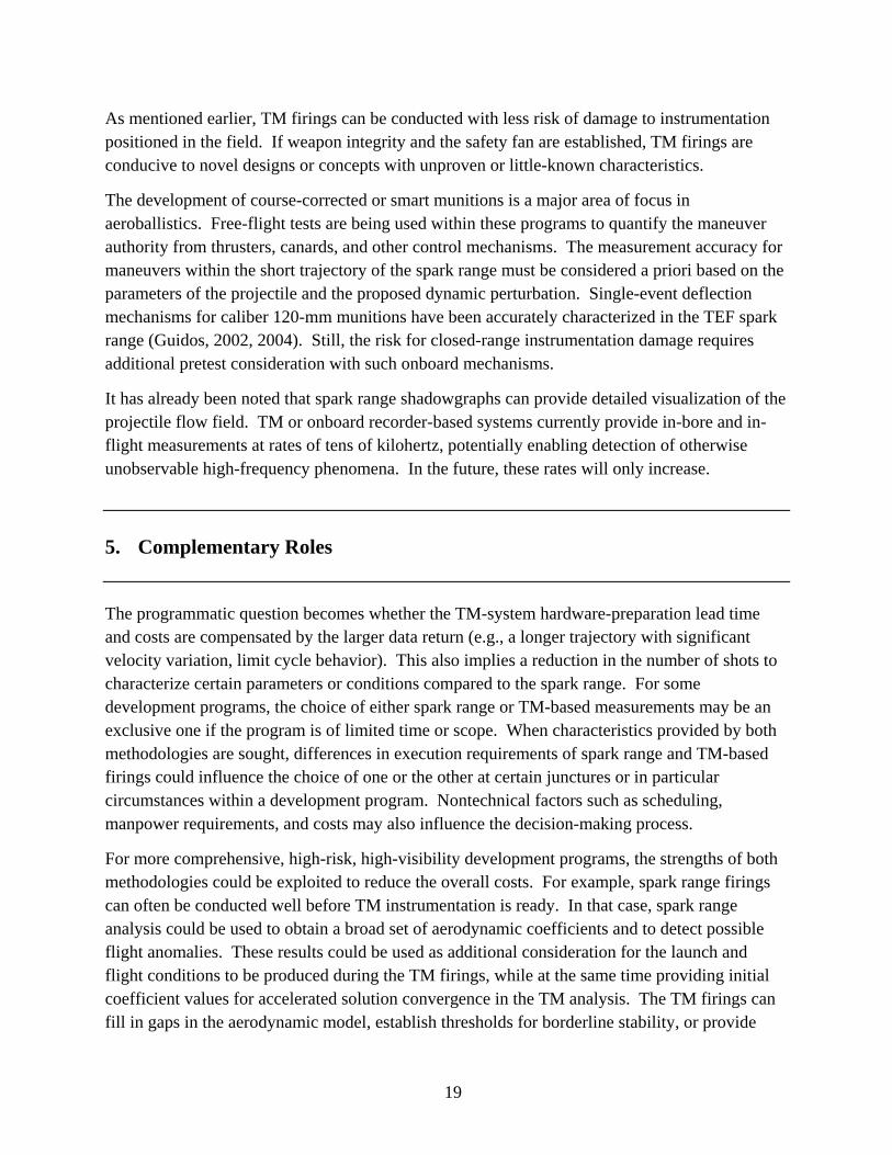
Using spark range and TM methodologies cooperatively should decrease the total number of firings without increasing the time or cost, increase the understanding of the flight dynamics and maneuvers, and reduce the risk of encountering programmatic pitfalls late in the program. ARL is currently participating in such a programmatic approach with NASA’s development of the new Crew Exploration Vehicle (CEV). Spark range firings and analyses have been conducted by Brown et al. (2008) at Eglin Air Force Base, FL, while TM instrumentation development, firings, and analyses have been conducted at ARL (Topper et al., 2007). Figure 13 shows the TM-instrumented CEV model fired from a 120-mm M256 M1A1 tank gun.
Figure 13. NASA CEV model fired from a 120-mm gun.
6. Conclusion
Many aspects of ground-based and TM-based free-flight measurement methodologies have been presented in this report. The descriptions provide insight into the technical capabilities as well as nontechnical challenges afforded by the two methodologies. Many projectile development programs have established objectives that generally indicate whether a spark range program, a TM program, or a combination of both is beneficial to success.
21
Some future areas of development in spark range and TM technology will likely affect the evolution of the considerations and synergy between the two methodologies.
Spark range methodology is technically mature but has potential to undergo modernization to further reduce costs and turnaround time. Two areas are noted: (1) replacement of film and associated chemicals with digital technology and (2) automated image reading. In that case, firing cadence will be determined by ballistics considerations rather than the manual process of loading and unloading film. Less on-site manpower will be required for firings. Shadowgraph images would be available for viewing 5 min after the shot (rather than 1 h). Film reading of all the shadowgraphs would be reduced from 1 h/shot to 5 min/shot. The semi-automated film-reading capability by Yates (1993) provides a clear indication that such automation is attainable. Current PC technology can easily handle the extra disk storage overhead associated with the digitized images, which would likely have a pixel density of 600 dpi.
TM methodology is currently mature enough to impact projectile development programs yet still has the potential for incredible technological advancement. Like spark range testing, cost and lead time for the current generation of instrumentation can be reduced. Modular board stacks are being utilized to maximize the uses of a single design. As hardware evolves, the individual parts of the TM system are getting smaller and better able to survive higher accelerations without loss of functionality. ARL is currently developing a new TM system that will double the number of analog channels and add several digital/discrete/serial channels without increasing size or cost. Upgrades are also planned to add additional sensors like GPS. Commercially available GPS boards are getting small enough and cheap enough to make accurate onboard position and velocity measurements both practicable and affordable for test and evaluation systems.
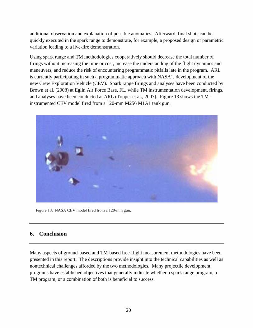
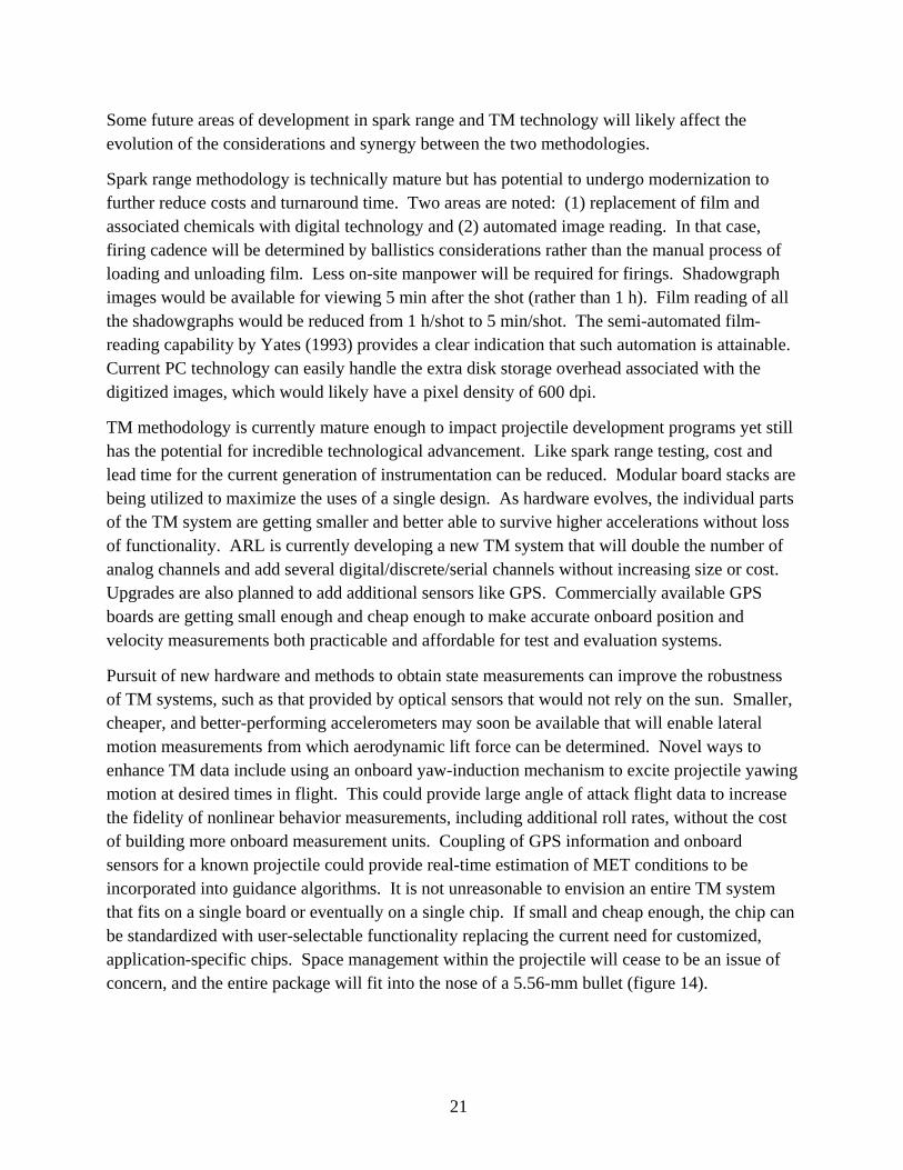
Pursuit of new hardware and methods to obtain state measurements can improve the robustness of TM systems, such as that provided by optical sensors that would not rely on the sun. Smaller, cheaper, and better-performing accelerometers may soon be available that will enable lateral motion measurements from which aerodynamic lift force can be determined. Novel ways to enhance TM data include using an onboard yaw-induction mechanism to excite projectile yawing motion at desired times in flight. This could provide large angle of attack flight data to increase the fidelity of nonlinear behavior measurements, including additional roll rates, without the cost of building more onboard measurement units. Coupling of GPS information and onboard sensors for a known projectile could provide real-time estimation of MET conditions to be incorporated into guidance algorithms. It is not unreasonable to envision an entire TM system that fits on a single board or eventually on a single chip. If small and cheap enough, the chip can be standardized with user-selectable functionality replacing the current need for customized, application-specific chips. Space management within the projectile will cease to be an issue of concern, and the entire package will fit into the nose of a 5.56-mm bullet (figure 14).
22
Figure 14. Caliber 5.56-mm projectile.
In the 35 years since the description of free-flight studies cited in this report’s introduction, there have not only been great advances in measurement technologies as discussed herein, but also dramatic developments and advances in many other areas related to projectile and airframe development. New maneuver mechanisms, propellants, hyper-velocity systems, materials (including dynamically deformable and so-called “smart” materials), etc., make possible things that were unimaginable not so very long ago. The pace of advancements will probably only quicken in the next 35 years. The combination of the possibilities offered by the likely development of novel flight bodies and maneuver systems and the increasing ability to observe in-flight airframe states makes for a busy and challenging future for free-flight experimentation.
23
7. References
Abate, G.; Klomfass, A. A New Method for Determining Aeroballistic Parameters From Flight Data. Proceedings of the 55th Aeroballistic Range Association Meeting, Frieberg, Germany, September 2004.
Arrow Tech Associates. ARFDAS 97 Version 4.00 Beta User Manual, South Burlington, VT, 1997a.
Arrow Tech Associates. PC PRODAS Version 3.9 User Manual, South Burlington, VT, 1997b.
Braun, W.; Charters, A.; Thomas, R. Retardation of Fragments; Report No. 425; U.S. Army Ballistics Research Laboratory: Aberdeen Proving Ground, MD, November 1943.
Brown, J.; Bogdonoff, D.; Yates, L.; Chapman, G. Free-Flight Aerodynamic Data for a Lifting CEV Capsule. 46th Aerospace Sciences Meeting; AIAA Paper 2008-1232; Reno, NV, January 2008.
Brown, T.; Brandon, F.; Harkins, T.; Hathaway, W. Drag and Moment Coefficients Measured During Flight Testing of a 2.75-Inch Rocket. 35th Aerospace Sciences Meeting & Exhibit; AIAA Paper 97-0634; Reno, NV, January 1997.
Chapman, G.; Kirk, D. A New Method for Extracting Aerodynamic Coefficients From Free-Flight Data. AIAA 7th Aerospace Sciences Meeting; AIAA Paper 69-134; New York, January 1969.
Chapman, G.; Kirk, D.; Malcolm, G. Aerodynamics of Bodies From Motion Analysis. In Ballistic-Range Technology; AGARDograph no. 138; Advisory Group for Aerospace Research and Development: Neuilly sur Seine, France, August 1970; pp 267–350.
Charters, A. The Linearized Equations of Motion Underlying the Dynamic Stability of Aircraft, Spinning Projectiles, and Symmetrical Missiles; NACA TN 3350; National Advisory Committee for Aeronautics: Langley Field, VA, 1955.
Charters, A. The Early Years of Aerodynamics Ranges, Light-Gas Guns, and High-Velocity Impact. Int. J. Impact Eng. 1995, 17, 151–182.
Charters, A.; Thomas, R. The Aerodynamic Performance of Small Spheres From Subsonic to High Supersonic Velocities; Report No. 514; U.S. Army Ballistics Research Laboratory: Aberdeen Proving Ground, MD, May 1945.
Clay, W. A Precision Yawsonde Calibration Technique; BRL-MR-2263; U.S. Army Ballistics Research Laboratory: Aberdeen Proving Ground, MD, January 1973.
24
Coltrane, L. Investigation of Two Bluff Shapes in Axial Free Flight Over a Mach Number Range From 0.35 to 2.15; NACA-RM-L58A16; National Advisory Committee for Aeronautics; Langley Field, VA, March 1958.
Davis, B. Comparison of Yawsonde and Transonic Range Data for the 155-mm M483A1 and XM898 Projectiles; BRL-MR-3919; U.S. Army Ballistics Research Laboratory: Aberdeen Proving Ground, MD, May 1991.
Davis, B. Comparison of Aerodynamic Coefficients for the M483A1 and XM898 Projectiles Determined From Transonic Range Data; BRL-MR-3999; U.S. Army Ballistics Research Laboratory: Aberdeen Proving Ground, MD, September 1992.
Davis, B.; Harkins, T.; Hepner, D.; Patton, B.; Hall, R. Aeroballistic Diagnostic Fuze (DFuze) Measurements for Projectile Development, Test, and Evaluation; ARL-TR-3204; U.S. Army Research Laboratory: Aberdeen Proving Ground, MD, July 2004.
Davis, B.; Hathaway, H.; Hathaway, A.; Thompson, A. Extending Telemetry Reduction to Aerodynamic Coefficients and Trajectory Reconstruction (EXTRACTR) Flight Experiment Using 155-mm M483A1 Projectiles; ARL-TR-3563; U.S. Army Research Laboratory: Aberdeen Proving Ground, MD, August 2005.
Davis, B.; Malejko, G.; Dohrn, R.; Owens, S.; Harkins, T.; Bischer, G. Addressing the Challenges of a Thruster-Based Precision Guided Mortar Munition With the Use of Embedded Telemetry Instrumentation. Proceedings of the 2007 Annual ITEA International Symposium, Lihue, HI, October 2007.
Fowler, R.; Gallop, E.; Lock, C.; Richmod, H. The Aerodynamics of a Spinning Shell. Philos. Trans. R. Soc. London, Ser. A 1921, 221, 295.
Gotlieb, C.; Pashler, P.; Rubinoff, M. A Radio Method of Studying the Yaw of Shells. Can. J. Res., A 1948, 26, 167–198.
Guidos, B. Measured and Modeled Effects of a Lateral Thruster on a Large-Caliber Finned Projectile. Proceedings of the 20th International Symposium on Ballistics, Orlando, FL, September 2002.
Guidos, B. Deflection Measurement Accuracy in a Course-Corrected 120-mm Mortar Spark Range Flight Experiment. Proceedings of the AIAA Atmospheric Flight Mechanics Conference, Providence, RI, August 2004.
Hathaway, A.; Hathaway, W.; Whyte, R.; Davis, B.; Brown, T.; Hepner, D.; Harkins, T. Combining Radar, Yawsonde, and On-Board Telemetry Data to Determine Aerodynamic Coefficients. Proceedings of the 51st Aeroballistic Range Association, Madrid, Spain, September 2000.
25
Hepner, D. J.; Hollis, M. S. L.; Muller, P. C.; Harkins, T. E.; Borgen, G.; D’Amico, W. P.; Davis, B. S.; Burke, L. W. Aeroballistic Diagnostic System. U.S. Patent 6349652, 26 February 2002.
Karpov, B. A Comparison of Aerodynamic Data Obtained by “Yaw Card” and Spark Photography Methods; Memorandum Report No. 728; U.S. Army Ballistics Research Laboratory: Aberdeen Proving Ground, MD, October 1953.
Kent, R. Notes on a Theory of Spinning Shell; BRL Report 898; U.S. Army Ballistics Research Laboratory: Aberdeen Proving Ground, MD, February 1954.
Lovas, A.; Brown, T.; Harkins, T. Innovative Technologies and Techniques for In-Situ Test and Evaluation of Small Caliber Munitions. Proceedings of the 2007 Annual ITEA International Symposium, Lihue, HI, October 2007.
McCoy, R. Modern Exterior Ballistics; Schiffer Publishing Ltd.: Atglen, PA, 1998.
McShane, E.; Kelley, J.; Reno, F. Exterior Ballistics; University of Denver Press: Denver, CO, 1953.
Mermagen, W.; Clay, W. The Design of a Second Generation Yawsonde; BRL-MR-2368; U.S. Army Ballistics Research Laboratory: Aberdeen Proving Ground, MD, April 1974.
Murphy, C. Data Reduction for the Free Flight Spark Ranges; BRL Report 900; U.S. Army Ballistics Research Laboratory: Aberdeen Proving Ground, MD, February 1954.
Murphy, C. The Measurement of Non-Linear Forces and Moments by Means of Free Flight Tests; BRL Report 974; U.S. Army Ballistics Research Laboratory: Aberdeen Proving Ground, MD, February 1956.
Murphy, C. Free Flight Motion of Symmetric Missiles; BRL-R-1216; U.S. Army Ballistics Research Laboratory: Aberdeen Proving Ground, MD, July 1963.
Schmidt, E. The Aerodynamics Range: A National Historic Mechanical Engineering Landmark; ARBRL-SP-00028; U.S. Army Ballistics Research Laboratory: Aberdeen Proving Ground, MD, May 1983.
Toledo, W.; Recchia, T. TELA 6-DOF Simulation. Data Exchange Agreement 1060 Advanced Technology for Smart Munitions Workshop, Aberdeen Proving Ground, MD, 21 October 2004.
Topper, B.; Brown, T.; Bukowski, E.; Davis, B.; Hall, R.; Vong, T.; Brandon, F. Feasibility of Determining Aerodynamic Coefficients for a NASA Apollo Body With the Use of Telemetry Data From Free Flight Range Testing; ARL-TR-4271; U.S. Army Research Laboratory: Aberdeen Proving Ground, MD, September 2007.
Van Dyke, M. An Album of Fluid Motion; Parabolic Press: Stanford, CA, 1982.

26
Whyte, R. Aerodynamic Coefficients of the M483A1 Determined From Spark Range Tests; BRL-CR-659; U.S. Army Ballistics Research Laboratory: Aberdeen Proving Ground, MD, April 1991.
Whyte, R.; Hathaway, W. On the Accuracy of Aerodynamic Coefficients Determined From Aeroballistic Range Tests. Proceedings of the 47th Meeting of the Aeroballistic Range Association, ISL, France, October 1996.
Whyte, R.; Mermagen, W. A Method for Obtaining Aerodynamic Coefficients From Yawsonde and Radar Data; BRL-MR-2280; U.S. Army Ballistics Research Laboratory: Aberdeen Proving Ground, MD, March 1973.
Whyte, R.; Jeung, A.; Bradley, J. Chapman-Kirk Reduction of Free-Flight Range Data to Obtain Aerodynamic Coefficients; BRL-MR-2298; U.S. Army Ballistics Research Laboratory: Aberdeen Proving Ground, MD, May 1973.
Wilson, M. Combining and Filtering Telemetry Data; ARL-TR-3143; U.S. Army Research Laboratory: Aberdeen Proving Ground, MD, March 2004.
Yates, L. Development of an Automated Film-Reading System for Ballistic Ranges. J. Spacecraft and Rockets 1993, 30 (2).

NO. OF COPIES ORGANIZATION
27
1 DEFENSE TECHNICAL (PDF INFORMATION CTR only) DTIC OCA 8725 JOHN J KINGMAN RD STE 0944 FORT BELVOIR VA 22060-6218 1 DIRECTOR US ARMY RESEARCH LAB IMNE ALC HRR 2800 POWDER MILL RD ADELPHI MD 20783-1197 1 DIRECTOR US ARMY RESEARCH LAB RDRL CIM L 2800 POWDER MILL RD ADELPHI MD 20783-1197 1 DIRECTOR US ARMY RESEARCH LAB RDRL CIM P 2800 POWDER MILL RD ADELPHI MD 20783-1197
ABERDEEN PROVING GROUND 1 DIR USARL RDRL CIM G (BLDG 4600)
NO. OF NO. OF COPIES ORGANIZATION COPIES ORGANIZATION
28
1 COMMANDER US ARMY TACOM ARDEC SFAE GCSS ARMS R KOWALSKI BLDG 171A PICATINNY ARSENAL NJ 07806-5000 1 COMMANDER US ARMY TACOM ARDEC AMSRD AAR AEM M V GONSALVES BLDG 61S PICATINNY ARSENAL NJ 07806-5000 1 COMMANDER US ARMY TACOM ARDEC AMSRD AAR EMO A MUSALLI BLDG 65S PICATINNY ARSENAL NJ 07806-5000 5 COMMANDER US ARMY TACOM ARDEC AMSRD AAR AEM C P MAGNOTTI D DEMELLA R GORMAN A LICHTENBURG-SCALON J MURNANE BLDG 61S PICATINNY ARSENAL NJ 07806-5000 4 COMMANDER US ARMY TACOM ARDEC AMSRD AAR AEM C M CORZO A READDY R LEE J COSME BLDG 94 PICATINNY ARSENAL NJ 07806-5000 1 COMMANDER US ARMY TACOM ARDEC AMSRD AAR AEW E H HUNTZINGER BLDG 65N PICATINNY ARSENAL NJ 07806-5000
1 COMMANDER US ARMY TACOM ARDEC AMSRD AAR AEW F M MCCRAE BLDG 171 PICATINNY ARSENAL NJ 07806-5000
1 COMMANDER US ARMY TACOM ARDEC AMSRD AAR AEW F S FLOROFF BLDG 61N PICATINNY ARSENAL NJ 07806-5000
5 COMMANDER US ARMY TACOM ARDEC AMSRD AAR AEM A Y CHEN M DUCA S HAN J THOMASOVICH D PEDERSEN BLDG 94 PICATINNY ARSENAL NJ 07806-5000
11 COMMANDER US ARMY TACOM ARDEC AMSRD AAR AEM A S CHUNG J GRAU W KOENIG C LIVECCHIA G MALEJKO W TOLEDO R TROHANOWSKY T RECCHIA E VAZQUEZ C WILSON L YEE BLDG 95 PICATINNY ARSENAL NJ 07806-5000
1 COMMANDER US ARMY TACOM ARDEC AMSRD AAR AEM A A FARINA BLDG 65N PICATINNY ARSENAL NJ 07806-5000
NO. OF NO. OF COPIES ORGANIZATION COPIES ORGANIZATION
29
1 COMMANDER US ARMY TACOM ARDEC AMSRD AAR AEM A B WONG BLDG 61S PICATINNY ARSENAL NJ 07806-5000 1 COMMANDER US ARMY TACOM ARDEC AMSRD AR AEP E C STOUT BLDG 94 PICATINNY ARSENAL NJ 07806-5000
1 COMMANDER US ARMY TACOM ARDEC AMSRD AAR AEP S R FULLERTON BLDG 94 PICATINNY ARSENAL NJ 07806-5000
2 COMMANDER US ARMY TACOM ARDEC AMSRD AAR AEM L E SCHEPER R CARR BLDG 65N PICATINNY ARSENAL NJ 07806-5000
4 COMMANDER US ARMY TACOM ARDEC AMSRD AAR AEM L A MOLINA M LUCIANO M PALATHINGAL D VO BLDG 65S PICATINNY ARSENAL NJ 07806-5000
1 COMMANDER US ARMY TACOM ARDEC AMSRD AAR AEM L J STRUCK BLDG 407 PICATINNY ARSENAL NJ 07806-5000
1 COMMANDER US ARMY TACOM ARDEC AMSRD AAR AIS SE D LUKE BLDG 172 PICATINNY ARSENAL NJ 07806-5000
7 COMMANDER US ARMY TACOM ARDEC SFAE AMO MAS MC M WANNER (5 CPS) G DEROSA D COLA BLDG 354 PICATINNY ARSENAL NJ 07806-5000 3 COMMANDER US ARMY TACOM ARDEC AMSRD AAR AEM J A PIZZA C SUMMA A SORCHINI BLDG 65N PICATINNY ARSENAL NJ 07806-5000
1 COMMANDER US ARMY TACOM ARDEC AMSRD AAR AEM J J GRASSI BLDG 64 PICATINNY ARSENAL NJ 07806-5000
1 COMMANDER US ARMY TACOM ARDEC AMSRD AAR AEM L E LOGSDON BLDG 65 PICATINNY ARSENAL NJ 07806-5000
1 COMMANDER US ARMY TACOM ARDEC AMSRD AAR MEM J G PACELLA BLDG 65N PICATINNY ARSENAL NJ 07806-5000
NO. OF NO. OF COPIES ORGANIZATION COPIES ORGANIZATION
30
1 COMMANDER US ARMY TACOM ARDEC AMSRD AAR MEM L R HOWELL BLDG 65S PICATINNY ARSENAL NJ 07806-5000
2 COMMANDER US ARMY TACOM ARDEC AMSRD AAR MEM C D NGUYEN V VERGARA BLDG 61S PICATINNY ARSENAL NJ 07806-5000
1 COMMANDER US ARMY TACOM ARDEC AMSRD AAR EIL L INGRASSIA BLDG 1 PICATINNY ARSENAL NJ 07806-5000 2 COMMANDER US ARMY TACOM ARDEC AMSRD AAR WSW F A JACOB C FISCHER BLDG 65N PICATINNY ARSENAL NJ 07806-5000 1 COMMANDER US ARMY TACOM ARDEC AMSTA AR CCL B R ALZAMORA BLDG 65N PICATINNY ARSENAL NJ 07806-5000 1 COMMANDER US ARMY TACOM ARDEC AMSTA AR CCL CA J DOUGLAS BLDG 65N PICATINNY ARSENAL NJ 07806-5000
1 COMMANDER US ARMY TACOM ARDEC AMSRD AAR WSW F F TORRES BLDG 65N PICATINNY ARSENAL NJ 07806-5000 1 COMMANDER US ARMY TACOM ARDEC AMSTA AR QES D D KATZ BLDG 92 PICATINNY ARSENAL NJ 07806-5000 1 COMMANDER US ARMY TACOM ARDEC AMSTA AR QEP B A ALMEIDA BLDG 354 PICATINNY ARSENAL NJ 07806-5000 1 COMMANDER US ARMY TACOM ARDEC AMSTA AR QEM B H WEBSTER BLDG 92 PICATINNY ARSENAL NJ 07806-5000 1 COMMANDER US ARMY TACOM ARDEC AMSTA AR QAC T M GONZALEZ BLDG 65N PICATINNY ARSENAL NJ 07806-5000 1 COMMANDER US ARMY TACOM ARDEC AMSTA AR WEA J OSTERNDORF BLDG 318 PICATINNY ARSENAL NJ 07806-5000 1 COMMANDER US ARMY TACOM ARDEC AMSRD AAR AIL P K LUU BLDG 455 PICATINNY ARSENAL NJ 07806-5000
NO. OF NO. OF COPIES ORGANIZATION COPIES ORGANIZATION
31
1 COMMANDER US ARMY TACOM ARDEC AMSRD AAR WSF N J WILLIS BLDG 95 PICATINNY ARSENAL NJ 07806-5000 1 CDR US ARMY TACOM ARDEC AMSRD AAR QEM E M BOMUS BLDG 65S PICATINNY ARSENAL NJ 07806-5000 1 CDR US ARMY TACOM ARDEC AMSTA AR FSA P A MOCK BLDG 171A PICATINNY ARSENAL NJ 07806-5000 1 CDR US ARMY TACOM ARDEC AMSRD AAR AEM C J POTUCEK BLDG 65S PICATINNY ARSENAL NJ 07806-5000 1 CDR US ARMY TACOM ARDEC AMSRD AAR MEF S PEARCY BLDG 94 PICATINNY ARSENAL NJ 07806-5000 1 CDR US ARMY TACOM ARDEC AMSRD AAR MEF E J VEGA BLDG 94 PICATINNY ARSENAL NJ 07806-5000 4 CDR US ARMY TACOM ARDEC AMSRD AAR AEP E P GRANGER R WERKO M HOLLIS J KALINOWSKI BLDG 94 PICATINNY ARSENAL NJ 07806-5000 1 CDR US ARMY TACOM ARDEC AMSRD AAR AEP E D TROAST BLDG 171 PICATINNY ARSENAL NJ 07806-5000
4 CDR US ARMY TACOM ARDEC AMSRD AAR AEP S N GRAY M MARSH Q HUYNH T ZAPATA BLDG 94 PICATINNY ARSENAL NJ 07806-5000 1 CDR US ARMY TACOM ARDEC AMSRD AAR AEP S C PEREIRA BLDG 407 PICATINNY ARSENAL NJ 07806-5000 1 CDR US ARMY TACOM ARDEC AMSRD AAR AEP F H RAND BLDG 61S PICATINNY ARSENAL NJ 07806-5000 1 CDR US ARMY TACOM ARDEC AMSRD AAR AEP F D PASCUA BLDG 94 PICATINNY ARSENAL NJ 07806-5000 2 CDR US ARMY TACOM ARDEC AMSRD AAR AEP I S LONGO C HALKIAS BLDG 95N PICATINNY ARSENAL NJ 07806-5000 1 CDR US ARMY TACOM ARDEC SFAE SDR SW IW B D AHMAD BLDG 151 PICATINNY ARSENAL NJ 07806-5000 2 PM MORTARS SFAE AMO CAS MS P BURKE D SUPER BLDG 162 PICATINNY ARSENAL NJ 07806-5000 2 PM MEDIUM CANNON CAL SFAE AMO MAS SMC J TERHUNE C GRASSANO BLDG 354 PICATINNY ARSENAL NJ 07806-5000
NO. OF NO. OF COPIES ORGANIZATION COPIES ORGANIZATION
32
1 PM EXCALIBUR SFAE AMO CAS EX G BISHER BLDG 162S PICATINNY ARSENAL NJ 07806-5000 1 DIRECTOR US ARMY RSRCH LAB RDRL SES J EICKE ADELPHI MD 20783-1197 1 DIRECTOR RDRL SES A J PRICE 2800 POWDER MILL RD ADELPHI MD 20783-1197 3 CDR US ARMY TACOM ARDEC AMSRD AAR MEF F(A) W KONICK C ROBINSON D WARD 2800 POWDER MILL RD ADELPHI MD 20783-1197 1 DIRECTOR US ARMY RSRCH LAB RDRL WMM B A FRYDMAN 2800 POWDER MILL RD ADELPHI MD 20783-1197 1 CDR NAVAL SURF WARFARE CTR H MALIN 6210 TISDALE RD STE 223 DAHLGREN VA 22448-5114 1 COMMANDER US ARMY RDECOM TARDEC AMSRD TAR R R JOZWIAK 6501 EAST 11 MILE RD MS 263 WARREN MI 48397-5000 1 COMMANDER US ARMY RDECOM TARDEC AMSRD TAR E T IANITELLI 6501 E 11 MILE RD MS 295 WARREN MI 48397-5000
3 ARROW TECH ASSOCIATES W HATHAWAY J SIEWART M STEINHOFF 1233 SHELBURNE RD STE 8 S BURLINGTON VT 05403 5 ALLIANT TECHSYSTEMS A GAUZENS J MILLS B LINDBLOOM E KOSCO D JACKSON PO BOX 4648 CLEARWATER FL 33758-4648 3 SAIC J GLISH J NORTHRUP G WILLENBRING 8500 NORMANDALE LAKE BLVD STE 1610 BLOOMINGTON MN 55437-3828 8 ALLIANT TECHSYSTEMS G PICKUS M WILSON B RAHN G GADACZ D KUKOWSKI B FRIEDRICH C LEMONT J FEIGUM 4700 NATHAN LN N PLYMOUTH MN 55442 10 ALLIANT TECHSYSTEMS S OWENS A DOW C FRITZ J CONDON S INGRAM B NYGA J PARRILL M WHITE S MCCLINTOCK K NYGA MS WV01 08 BLDG 300 RM 180 210 STATE RTE 956 ROCKET CENTER WV 26726-3548
NO. OF NO. OF COPIES ORGANIZATION COPIES ORGANIZATION
33
1 SAIC D HALL 1150 FIRST AVE STE 400 KING OF PRUSSIA PA 19406 1 AAI CORPORATION MS 113 141 C BEVARD 124 INDUSTRY LANE HUNT VALLEY MD 21030 2 CHLS STARK DRAPER LAB T EASTERLY A KOUREPENIS 555 TCHNLGY SQ CAMBRIDGE MA 02139-3563 2 TRAX INTL R GIVEN J SWAIN BLDG 2023E YUMA PROVING GROUND AZ 85365 1 GD OTS E KASSHEIMER PO BOX 127 RED LION PA 17356 1 ALION SCIENCE P KISATSKY 12 PEACE RD RANDOLPH NJ 07861 1 GEORGIA TECH RSRCH INST GTRI ATAS A LOVAS SMYRNA GA 30080 3 BAE SYSTEMS T MELODY T BLUMER C BIES MS380 4800 EAST RIVER RD MINNEAPOLIS MN 55421-1498 1 CUSTOM ANALYTICAL ENG SYS A ALEXANDER 13000 TENSOR LN N FLINTSTONE MD 21530
ABERDEEN PROVING GROUND 7 COMMANDER US ARMY ATC BLDG 400 J DAMIANO R SCHNELL J KOPP T GARCIA J GWALTNEY S BENJAMIN K MCMULLEN APG MD 21005 5 COMMANDER US ARMY TACOM ARDEC AMSRD AR AEF D B305 R LIESKE J MATTS A SOWA M ANDRIOLO J FONNER APG MD 21005 38 DIR USARL RDRL WMB M ZOLTOSKI RDRL WMB A D LYON J CONDON B DAVIS (3 CPS) T HARKINS (3 CPS) D HEPNER G KATULKA E BUKOWSKI P MULLER P PEREGINO T BROWN R HALL B PATTON T KOGLER M ILG RDRL WMB C J SAHU P WEINACHT B GUIDOS (3 CPS) B HOWELL S SILTON I CELMINS G COOPER J DESPIRITO

NO. OF COPIES ORGANIZATION
34
J GARNER G OBERLIN F FRESCONI RDRL WMT C T BJERKE R MUDD T DIGLIANI R SUMMERS T FARRAND RDRL SLB A G BRADLEY


![CENTERITY SERVICE PACK FOR CLOUDERA€¦ · OOZIE [roles status] • CLOUDERA ROLES SOLR [roles status] • CLOUDERA ROLES SPARK [roles status] • CLOUDERA ROLES SQOOP [roles status]](https://static.fdocuments.in/doc/165x107/5fc0df6d43307a59a12ae0a7/centerity-service-pack-for-cloudera-oozie-roles-status-a-cloudera-roles-solr.jpg)


