COMPASS Final Report: Lunar Communications Terminal (LCT) · Steven R. Oleson and Melissa L....
42
Steven R. Oleson and Melissa L. McGuire Glenn Research Center, Cleveland, Ohio COMPASS Final Report: Lunar Communications Terminal (LCT) NASA/TM—2010-216236 December 2010 CD–2007–11 https://ntrs.nasa.gov/search.jsp?R=20110004245 2018-07-15T04:37:31+00:00Z
Transcript of COMPASS Final Report: Lunar Communications Terminal (LCT) · Steven R. Oleson and Melissa L....

Steven R. Oleson and Melissa L. McGuireGlenn Research Center, Cleveland, Ohio
COMPASS Final Report: Lunar Communications Terminal (LCT)
NASA/TM—2010-216236
December 2010
CD–2007–11
https://ntrs.nasa.gov/search.jsp?R=20110004245 2018-07-15T04:37:31+00:00Z

NASA STI Program . . . in Profi le
Since its founding, NASA has been dedicated to the advancement of aeronautics and space science. The NASA Scientifi c and Technical Information (STI) program plays a key part in helping NASA maintain this important role.
The NASA STI Program operates under the auspices of the Agency Chief Information Offi cer. It collects, organizes, provides for archiving, and disseminates NASA’s STI. The NASA STI program provides access to the NASA Aeronautics and Space Database and its public interface, the NASA Technical Reports Server, thus providing one of the largest collections of aeronautical and space science STI in the world. Results are published in both non-NASA channels and by NASA in the NASA STI Report Series, which includes the following report types: • TECHNICAL PUBLICATION. Reports of
completed research or a major signifi cant phase of research that present the results of NASA programs and include extensive data or theoretical analysis. Includes compilations of signifi cant scientifi c and technical data and information deemed to be of continuing reference value. NASA counterpart of peer-reviewed formal professional papers but has less stringent limitations on manuscript length and extent of graphic presentations.
• TECHNICAL MEMORANDUM. Scientifi c
and technical fi ndings that are preliminary or of specialized interest, e.g., quick release reports, working papers, and bibliographies that contain minimal annotation. Does not contain extensive analysis.
• CONTRACTOR REPORT. Scientifi c and
technical fi ndings by NASA-sponsored contractors and grantees.
• CONFERENCE PUBLICATION. Collected papers from scientifi c and technical conferences, symposia, seminars, or other meetings sponsored or cosponsored by NASA.
• SPECIAL PUBLICATION. Scientifi c,
technical, or historical information from NASA programs, projects, and missions, often concerned with subjects having substantial public interest.
• TECHNICAL TRANSLATION. English-
language translations of foreign scientifi c and technical material pertinent to NASA’s mission.
Specialized services also include creating custom thesauri, building customized databases, organizing and publishing research results.
For more information about the NASA STI program, see the following:
• Access the NASA STI program home page at http://www.sti.nasa.gov
• E-mail your question via the Internet to help@
sti.nasa.gov • Fax your question to the NASA STI Help Desk
at 443–757–5803 • Telephone the NASA STI Help Desk at 443–757–5802 • Write to:
NASA Center for AeroSpace Information (CASI) 7115 Standard Drive Hanover, MD 21076–1320
Steven R. Oleson and Melissa L. McGuireGlenn Research Center, Cleveland, Ohio
COMPASS Final Report: Lunar Communications Terminal (LCT)
NASA/TM—2010-216236
December 2010
CD–2007–11
National Aeronautics andSpace Administration
Glenn Research CenterCleveland, Ohio 44135

Available from
NASA Center for Aerospace Information7115 Standard DriveHanover, MD 21076–1320
National Technical Information Service5301 Shawnee Road
Alexandria, VA 22312
Available electronically at http://gltrs.grc.nasa.gov
Trade names and trademarks are used in this report for identifi cation only. Their usage does not constitute an offi cial endorsement, either expressed or implied, by the National Aeronautics and
Space Administration.
Level of Review: This material has been technically reviewed by technical management.
This report is a formal draft or working paper, intended to solicit comments and
ideas from a technical peer group.
This report contains preliminary fi ndings, subject to revision as analysis proceeds.

NASA/TM—2010-216236 iii iii
Contents 1.0 Executive Summary ............................................................................................................................. 1 2.0 Study Background and Assumptions ................................................................................................... 2
2.1 Introduction ................................................................................................................................. 2 2.2 Assumptions ................................................................................................................................ 2 2.3 Growth, Contingency and Margin Policy ................................................................................... 2 2.4 Mission Description .................................................................................................................... 3 2.5 System Design Trade Space ........................................................................................................ 4 2.6 Baseline System .......................................................................................................................... 4
3.0 Baseline Design .................................................................................................................................... 4 3.1 Top Level Design (MEL and PEL) ............................................................................................. 4
3.1.1 Master Equipment List (MEL) ...................................................................................... 4 3.1.2 Power Equipment List (PEL) ........................................................................................ 6
3.2 Design Concept Drawing and Description .................................................................................. 7 4.0 Subsystem Breakdown ......................................................................................................................... 7
4.1 Communications ......................................................................................................................... 7 4.1.1 Communications Assumptions/Requirements .............................................................. 7 4.1.2 Communications Design and MEL ............................................................................... 9 4.1.3 Communications Analytical Methods ........................................................................... 9 4.1.4 Communications Risk Inputs ...................................................................................... 10 4.1.5 Communications Findings .......................................................................................... 11
4.2 C&DH ....................................................................................................................................... 11 4.2.1 C&DH Requirements .................................................................................................. 11 4.2.2 C&DH Assumptions ................................................................................................... 12 4.2.3 C&DH Design and MEL ............................................................................................. 12 4.2.4 C&DH Trades ............................................................................................................. 12 4.2.5 C&DH Analytical Methods ......................................................................................... 12 4.2.6 C&DH Risk Inputs ...................................................................................................... 13 4.2.7 C&DH Findings .......................................................................................................... 13
4.3 Electrical Power System ........................................................................................................... 14 4.3.1 Power Requirements ................................................................................................... 14 4.3.2 Power Assumptions ..................................................................................................... 14 4.3.3 Power Design and MEL .............................................................................................. 14 4.3.4 Power Trades ............................................................................................................... 14 4.3.5 Power Analytical Methods .......................................................................................... 14
4.4 Structures and Mechanical Systems .......................................................................................... 15 4.4.1 Structures and Mechanical Systems Requirements ..................................................... 15 4.4.2 Structures and Mechanical Systems Assumptions ...................................................... 15 4.4.3 Structures and Mechanical Systems Design and MEL ............................................... 15 4.4.4 Structures and Mechanical Systems Trades ................................................................ 16 4.4.5 Structures and Mechanical Systems Analytical Methods ........................................... 16 4.4.6 Structures and Mechanical Systems Risk Inputs ......................................................... 16 4.4.7 Structures and Mechanisms Recommendation ........................................................... 16
4.5 Thermal Control ........................................................................................................................ 16 4.5.1 Thermal Requirements ................................................................................................ 16 4.5.2 Thermal Assumptions ................................................................................................. 17 4.5.3 Thermal Design and MEL ........................................................................................... 17 4.5.4 Thermal Risk Inputs .................................................................................................... 17
5.0 Avionics Software .............................................................................................................................. 18 5.1 Software Modeling Objectives.................................................................................................. 18
NASA/TM—2010-216236 iv iv
5.2 Assumptions .............................................................................................................................. 18 5.3 Approach ................................................................................................................................... 18
6.0 Cost and Risk ..................................................................................................................................... 18 6.1 Costing ...................................................................................................................................... 18 6.2 Risk Analysis and Reduction .................................................................................................... 18
6.2.1 Assumptions ................................................................................................................ 18 6.2.2 LCT Risk List .............................................................................................................. 19 6.2.3 Risk Summary ............................................................................................................. 19
7.0 Trade Space Iterations ........................................................................................................................ 19 7.1 Integrated LCT—Habitat/Lander Deployed at the South Pole ................................................. 19
7.1.1 Integrated LCT Design and MEL ............................................................................... 20 7.1.2 Communications—Integrated LCT ............................................................................. 21 7.1.3 C&DH—Integrated LCT ............................................................................................ 21 7.1.4 Power—Integrated LCT .............................................................................................. 21 7.1.5 Structures—Integrated LCT ........................................................................................ 21 7.1.6 Thermal Control—Integrated LCT ............................................................................. 22
7.2 Fixed Base User Radio (Mini-LCT) ......................................................................................... 22 7.2.1 Mini-LCT Design and MEL ........................................................................................ 23 7.2.2 Communications—Mini-LCT ..................................................................................... 24 7.2.3 C&DH—Mini-LCT..................................................................................................... 24 7.2.4 Power—Mini-LCT ...................................................................................................... 25 7.2.5 Structures—Mini-LCT ................................................................................................ 25 7.2.6 Thermal—Mini-LCT................................................................................................... 26
Appendix A.—Acronyms and Abbreviations ............................................................................................. 27 Appendix B.—Rendered Design Drawings ................................................................................................ 29
B.1 Rendered Design Drawings—LCT ........................................................................................... 29 B.2 Rendered Design Drawings—Integrated LCT .......................................................................... 31 B.3 Rendered Design Drawings—Mini-LCT .................................................................................. 32
Appendix C.—Study Participants ............................................................................................................... 33

NASA/TM—2010-216236 1 1
COMPASS Final Report: Lunar Communications Terminal (LCT)
Steven R. Oleson and Melissa L. McGuire
National Aeronautics and Space Administration Glenn Research Center Cleveland, Ohio 44135
1.0 Executive Summary The Lunar Communications Terminal (LCT) COllaborative Modeling and Parametric Assessment of
Space Systems (COMPASS) session designed a terminal to provide communications between lunar South Pole assets, communications relay to/from these assets through an orbiting Lunar Relay Satellite (LRS) and navigation support. The design included a complete master equipment list, power requirement list, configuration design, and brief risk assessment and cost analysis. The Terminal consists of a pallet containing the communications and avionics equipment, surrounded by the thermal control system (radiator), an attached, deployable 10-m tower, upon which were mounted locally broadcasting and receiving modems and a deployable 1 m diameter Ka/S band dish which provides relay communications with the lunar relay satellites and, as a backup, Earth when it is in view. All power was assumed to come from the lunar outpost Habitat.
Three LCT design options were explored: a stand-alone LCT servicing the manned outpost, an integrated LCT (into the Habitat or Lunar Lander), and a mini-LCT which provides a reduced level of communication for primarily robotic areas dealing as in situ resource utilization (ISRU) and remote science. Where possible all the designs assumed single fault tolerance. Significant mass savings were found when integrating the LCT into the Habitat or Lander but increases in costs occurred depending upon the level of man rating required for such designs.
Figure 1.1—A notional artist rendering of the LCT and LRS systems in use at the lunar South Pole.
NASA/TM—2010-216236 2 2
2.0 Study Background and Assumptions 2.1 Introduction
During crewed missions to the Moon, there is a need for redundant communications paths to Earth. For early, shorter duration missions, direct to Earth (DTE) and relay provide dual paths. For missions longer than the 2-wk two LRS are required for continuous coverage.
During the crewed phase, communication and navigation services are primarily provided via relay, in conjunction with a surface LCT, in support of the outpost. This LCT also provides outpost communications interconnectivity using 802-network technology.
In all cases, the nominal communications operations include all outpost vicinity communications routed through the LCT to other local users or to the relay. The LRS and LCT will provide these basic communication and navigation services:
• Forward command • Return mission data and telemetry • One- and two-way ranging and Doppler tracking • Beacon signals • In situ routing
2.2 Assumptions
Three LCT designs were completed. Some of the common assumptions are as follows: • LCT provides Comm/Nav for piloted missions • Delivered on Lunar Surface Access Module (LSAM) • Seven year mission, extendable to 10 yr • Single Fault Tolerant (except for some cases where LCT is integrated into the Habitat) For this study, the established figures of merit (FOM) were: cost, portability, and flexibility
2.3 Growth, Contingency and Margin Policy
Because the LCT design is more akin to a small spacecraft, the mass growth allowance policy used in the science community through the Discover Proposal process is applied to this study.
Practice for Mass Properties Control for Satellites, Missiles, and Launch Vehicles. Table 2.1 shows the growth percentage based on design maturity and design area. Percent mass growth divided by design maturity and subsystem.
Once the percent growth factors are applied on a subsystem per subsystem basis, the total system growth of the design is calculated. The COMPASS system desired total average mass growth allowance (MGA) to be 30%, and an additional growth is carried at the system level in order to add up to a total system growth of 30% on the dry mass of the system.
From the Discovery Announcement of Opportunity (AO): Definitions of Contingency and Mass Contingency (or Reserve or Growth), when added to a resource, results in the maximum expected
value for that resource. Percent contingency is the value of the contingency divided by the value of the resource less the contingency.
Margin is the difference between the maximum possible value of a resource (the physical limit or the agree-to limit) and the maximum expected value for a resource. Percent margin for a resource is the available margin divided by its maximum expected value.

NASA/TM—2010-216236 3 3
Power Growth: The COMPASS team uses a 30% growth factor. While instructions from Architecture Requirements Document (ARD) require an additional 10% of the dry mass of the LCT to be carried in our Master Equipment List (MEL) for attachments to attach the LCT onto the LSAM for delivery, this 10% was NOT assessed to avoid double-bookkeeping when LSAM teams begin to integrate the LCT. These attachments need to be carried either in the LSAM MEL or brought back to the LCT design as a lean on our system.
TABLE 2.1—COMPASS MASS GROWTH ALLOWANCE POLICY
Code Design Maturity (Basis for Mass Determination)
Percent Mass Growth Allowance
Electrical/Electronic Components
Stru
ctur
e
Ther
mal
Con
trol
Prop
ulsi
on
Bat
terie
s
Wire
Har
ness
es
Mec
hani
sms
Inst
rum
enta
tion
0-5 kg
5-15 kg
>15 kg
E Estimated (preliminary sketches) 30 20 15 18 18 18 20 50 18 50
L Layout
(or major modification of existing hardware)
25 20 15 12 12 12 15 30 12 30
P Pre-Release Drawings (or minor modification of existing hardware)
20 15 10 8 8 8 10 25 8 25
C Released Drawings (calculated values) 10 5 5 4 4 4 5 5 4 5
X Existing Hardware (actual mass from another program)
3 3 3 2 2 2 3 3 2 3
A Actual Mass
(measured flight hardware)
0 0 0 0 0 0 0 0 0 0
CFE Customer Furnished Equipment 0 0 0 0 0 0 0 0 0 0
2.4 Mission Description
A representative LCT Deployment Timeline from LAT2 Option no. 1 (documented in LAT2 reports) is as follows:
• LCT standby power and health monitoring via LSAM during cruise and post landing • LSAM ascent stage departs • Space Power Unit (SPU)/Mobile Power Unit (MPU) deployments, activation and checkouts occur • LCT is powered up and system checkouts occur while stowed • Stand-alone LCT deployed, integrated LCT deployed on Lander or Habitat • Ka-band antenna boom is deployed and acquires Earth • Ka-band system acquires and tracks LRS1 • Surface communication tower is deployed and tested • LCT operations to communicate with surface assets (e.g., rovers) and crewed LSAM and outpost
components • LCT provides communication and navigation services for subsequent LSAM landings

NASA/TM—2010-216236 4 4
• Stand-alone or mini-LCT moved as needed.
2.5 System Design Trade Space
The LCT design team looked at one baseline option and two variant configurations of the LCT in order to determine impacts to cost and design. The baseline design has the LCT as a completely stand-alone item, flown to the Moon on the first unmanned LSAM lunar flight. After being deployed to the lunar surface, the LCT contains all the communications and avionics hardware necessary to provide terminal communications for the outpost to/from the LRS.
The first variant option involves building the LCT as an integral part of the Habitat or as an integral part of the Lander, leveraging off of existing communications, power, thermal, structure and avionics hardware already contained on the LSAM vehicles. The second variant is a mini-LCT, which provides lower throughput communications mainly for robotic areas such as ISRU and science locations.
2.6 Baseline System
The basic design consists of a tower, and an avionics box, with the necessary thermal to withstand the lunar environment and the necessary structure to house the electronics and withstand both the lunar environment and also the launch and flight environment of the LSAM upon which it arrives at the Moon. This LCT is delivered to the Moon by the Lunar Lander as payload and is deployed either autonomously or by astronauts.
3.0 Baseline Design Figure 3.1 details the major components of the stand-alone LCT design. A 10 m boom holds the
wireless local area network (WLAN) antenna (depicted off the scope of the cropped Figure 3.1. See Figure 3.2 for the full scale LCT). A 1 m Ka/S-band antenna is deployed on a boom on the opposite side of the electronics box from the telescoping WLAN boom.
3.1 Top Level Design (MEL and PEL)
3.1.1 Master Equipment List (MEL) The MEL (Table 3.1) captures the bottoms-up estimation of current best estimate (CBE) and growth
percentage line item by item from the subsystem designer. The table below wraps up those total masses, CBE and total mass after applied growth percentage. In order to meet the total of 30% at the system level, an allocation is necessary for system level growth. In this case, an additional 11% is carried (36.8 kg) at the system level in order to total the 104.3 kg total growth. With this system grown, the CBE dry mass of the LCT is 349.4 kg and with bottoms up growth estimations per subsystem the total mass is 417.4 kg.
TABLE 3.1—TOP LEVEL LCT MEL WITHOUT SYSTEM GROWTH Description CBE
mass (kg)
Growth (%)
Growth mass (kg)
Total mass (kg)
Nominal power (W)
Peak power (W)
LCT System 349.4 19.5 68.0 417.4 ------- ------- LCT Tower 349.4 19.5 68.0 417.4 420.8 450.8 LCT Communications Package (from MEL 1.2) 85.6 21.8 18.6 104.2 258.2 288.2 Command and Data Handling 62.5 24.9 15.6 78.1 162.6 162.6 Power 46.8 42.9 20.1 66.9 0 0 Structures & Mechanical Systems 88.6 10.3 9.1 97.7 0 0 Thermal Control (Non-Propellant) 66.0 6.9 4.6 70.5 0 0

NASA/TM—2010-216236 5 5
Figure 3.1—Deployed stand alone LCT (note, 10 m boom off top of picture).
Table 3.2 further details subsystems as a percent of total mass of the system. This percentage is calculated by dividing the total mass of the subsystem (after growth is added) by the total mass of the LCT Bus plus Comm.
TABLE 3.2—LCT MEL WITH SYSTEM GROWTH CALCULATIONS
LCT MEL (mass)
CBE (kg)
Growth (%)
Growth (kg)
Total mass (kg)
% of total mass
LCT Communications Package 85.6 22 18.6 104 25.0 LCT Bus ---- ---- ---- ---- 75.0 Command and Data Handling 62.5 25 15.6 78.1 18.7 Power 46.8 43 20.1 66.9 16.0 Structures and Mechanical Systems 88.6 10 9.1 97.7 23.4 Thermal Control 66.0 7 4.6 70.5 16.9 LCT Bus Mass (w/o System Growth) 263.9 18.7 49.4 313.2
LCT Bus + Comm Package Mass 349.4 19 68.0 417.4 Desired System Growth (Contingency) 349.4 30 104.8 454.3 Added System Level Growth (Contingency) N/A 11 36.9 ---- LCT Total Mass (w/ system growth) 349.4 30.00 104.8 454.3
Note: 10% for LSAM attachments per ARD instructions not included

NASA/TM—2010-216236 6 6
Figure 3.2—Full scale, deployed LCT and stowed LCT with major components labeled.
3.1.2 Power Equipment List (PEL) The Power listing for nominal loads is contributed to only by the Communications and the Command
and Data Handing (C&DH) subsystems. The peak power for communications is currently higher than the nominal power. Two modems are operating at the same time in the peak situation, where only one operates nominally. The power system is sized to draw enough power from the LSAM Habitat to support the peak power needs of LCT.

NASA/TM—2010-216236 7 7
Table 3.3 racks up the power requirements per the two major systems of the LCT. The communications system requires 258.2 kWe nominal power, while the rest of the LCT bus (all from C&DH) requires 162.6 kWe. This makes for a total requirement of 421 kWe nominal power. The total peak power requirements are calculated similarly and are 451 kWe. This peak power increase in found in the Communications package.
TABLE 3.3—LCT PEL
LCT PEL Nominal power (W)
Peak power (W)
LCT Communications Package 258.2 288.2 LCT Bus 162.6 162.6 C&DH Power Structures and Mechanical Systems Thermal Control (Non-Propellant)
162.6 162.6 0 0 0 0 0 0
Total LCT Tower 421 451
3.2 Design Concept Drawing and Description
Figure 3.2 shows the deployed and stowed configuration of the stand-alone LCT design with dimensions of the booms and electronics housing. Note that the antenna in the stowed position points down to protect the electronics and mechanisms from lunar dust on landing.
4.0 Subsystem Breakdown 4.1 Communications
The Communications package was designed by a team at NASA Glenn Research Center (GRC) operating in parallel with the COMPASS design team. The LCT communication package was incorporated into the LCT overall COMPASS design through the use of GLIDE and the COMPASS design process. A separate report will be generated on the LCT communications package itself.
4.1.1 Communications Assumptions/Requirements • Estimate ~120 kg, ~625 W peak • Ka bi-directional links to LRS and for DTE supports 2 X 100 Mbps return • S-band high gain antenna (HGA), low gain antenna (LGA) bi-directional links to LRS and DTE • Includes 802.16 WiMax functionality for 2 to 6 km range, ≤80 Mbps • Does not include HF (high frequency, 1 to 30 MHz) or over the horizon (OTH) • Much Crew Exploration Vehicle (CEV), Lunar Reconnaissance Orbiter (LRO), commercial space
heritage • 802.16—terrestrial heritage • Only 1 S-band transponder on at a time
4.1.1.1 Communications Issues With Deployment and Lander Integration • Integration of LCT high gain Ka band antenna with high gain S band cup antenna
– Antenna folds down on top of box in the stowed configuration; should be face down to protect from dust and plumes.
– Propellants may stick to antenna due to cold temperatures. – Antenna is very sensitive to dust and ablation which increase loss due to surface roughness. If
the antenna’s original surface roughness (1/40th wavelength) is increased to 1/10th, there will be a 2X (3 dB) decrease in antenna gain and twice the power will be needed for the same effective isotropic radiated power (EIRP). Receiver noise temperature will also increase.

NASA/TM—2010-216236 8 8
– Selected 1-m composite antenna from LRO to save weight over aluminum and for flight heritage at new spectrum. Composite antenna is cold sensitive (cracking), needs both heaters and insulation blankets (all the time).
– Ka-antenna is on a 3.5 m boom to clear obstruction on Landers. If we can specify attitude of Lander with respect to Earth within 30° will not need this. This antenna is self-leveling.
• 802.16 WLAN sector antenna on 10-m boom – The 10 m boom is necessary to increase line-of-sight coverage to ~6 km around Hab. – Electronics were kept off boom to reduce mass but will investigate putting low noise
amplifiers behind sector antennas to reduce system noise temperature. – Boom (Astronaut from International Space Station) retracts and folds down by the box. Boom
is self-leveling. – Boom can be sticky to retract, so prefer human help. Tech development is needed in this area
since limits Concept of Operations (CONOPS). • Low gain S band omni antenna, Box of electronics and radiator
– Can be repackaged to different shapes. We prefer it to lie flat for stability. – Radiator on top for high gain electronics. Radiator must not see the Sun. For the poles, it
faces up, and the Sun is always below 5° on the horizon. Need more info for Mobile Lander. If box is mounted vertically, will need to make the radiator a fold out or tap into another radiator.
– LCT electronics in general can withstand low temperatures of –20 to –30 °C and high temperatures of 60 to 70 °C. Will need keep warm power at all times including during launch and transit. Not carrying own batteries.
4.1.1.2 The LCT Field of View • Ka band high gain antenna with S band high gain cup antenna
– Ka antenna tracks LRS slowly across sky. (They are in view ~8 hr of their 12 hr elliptical orbit and ~37° max inclination). The antennas will switch from one LRS to another.
– Alternatively, Ka antenna can track and communicate directly with Earth for part of the month. Earth rises and falls ~ 2° above/below horizon with ~1° lateral motion. LCT at Ka band could have unobstructed view of Earth when inclination is more than 1° above horizon.
– Ka/S band high gain antenna view will be obstructed by 802.16 open boom. Need to minimize Lander/other payload obstructions. Ka/S band high gain antenna will be able to be gimbaled through entire hemisphere after deployment on short mast. When HGA is deployed on Lander from high bay, the short mast allows it to have view the Earth and track LRS even if Lander is oriented with Ka on opposite side of Lander from Earth.
• 802.16 WLAN sector antenna on 10-m boom – Antenna must be at least 10 m above surface to increase line-of-sight range to the desired ~6 km.
This can be accomplished through a combination of boom and Lander height. • S band omni antenna/radiator
– Must not face Sun. At the South Pole, radiator point face up while Sun remains below 5° from horizon.

NASA/TM—2010-216236 9 9
Figure 4.1—Illumination of the lunar South Pole landing zone and landing approach details.
Figure 4.1 illustrates the projected landing sites for the lunar South Pole mission. The grey zones show the illumination percentage for power and communications sizing.
4.1.2 Communications Design and MEL
4.1.3 Communications Analytical Methods • Sized down from the ATS-3 150 Mbps modulator designed by Dr. Chen at Comdev (a developer
of the modulator) using LCT requirements of power and mass for a complete 100 Mbps modulating modem.
• WLAN base station based upon medium power, not high power commercial base station
NASA/TM—2010-216236 10 10
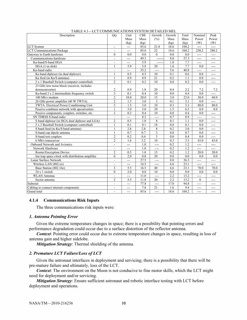
TABLE 4.1—LCT COMMUNICATIONS SYSTEM DETAILED MEL Description Qty Unit
Mass (kg)
CBE Mass (kg)
Growth (%)
Growth Mass (kg)
Total Mass (kg)
Nominal Power (W)
Peak Power (W)
LCT System - --- 85.6 21.8 18.6 104.2 ---- ---- LCT Communications Package - --- 85.6 22 18.6 104.2 258.2 288.2 Gateway to Earth hardware 0 0.0 0.0 0 0.0 0.0 ---- ---- Communications hardware - --- 49.3 ------ 8.0 57.3 ---- ---- Ka-band/S-band HGA - --- 5.9 ------ 1.8 7.7 ---- ---- HGA (1-m dish) 1 5.9 5.9 30 1.8 7.7 0.0 ---- Ka-band radio - --- 35.2 ---- 5.6 40.8 ---- ---- Ka band diplexer (in dual diplexer) 1 0.5 0.5 10 0.1 0.6 0.0 ---- Ka feed (in Ka/S antenna) 1 0.9 0.9 21 0.2 1.1 0.0 ---- 2 x 1 Baseball Switch (computer controlled) 2 0.1 0.2 10 0.0 0.2 0.0 ---- 23 GHz low noise block (receiver, includes downconverter) 2 0.9 1.8 20 0.4 2.2 7.2 7.2 Ka-band 2 x 2 intermediate frequency switch 3 0.1 0.4 10 0.0 0.4 0.0 ---- 100 Mb/s modem 2 10.0 20.0 15 3.0 23.0 30.0 60.0 26 GHz power amplifier (40 W TWTA) 2 1.5 3.0 3 0.1 3.1 0.0 ---- TWTA Electrical Power Conditioning Unit 2 1.5 3.0 10 0.3 3.3 80.0 80.0 Passive combiner network with upconverters 1 5.0 5.0 30 1.5 6.5 8.0 8.0 Passive components, couplers, switches, etc. 2 0.2 0.4 10 0.0 0.4 0.0 ---- SN TDRSS S-band radio - --- 8.2 ---- 0.7 8.9 ---- ---- S band diplexer (in HGA dual diplexer and LGA) 2 0.5 1.0 8 0.1 1.1 0.0 ---- 2 x 2 Baseball Switch (computer controlled) 1 0.1 0.1 18 0.0 0.1 0.0 ---- S band feed (in Ka/S band antenna) 1 2.8 2.8 8 0.2 3.0 0.0 ---- S-band cup dipole antenna 1 0.7 0.7 3 0.0 0.7 0.0 ---- S-band test couplers 2 0.2 0.4 3 0.0 0.4 0.0 ---- 6 Mb/s transceiver 2 1.6 3.2 10 0.3 3.5 43.0 43.0 Onboard Network and Avionics - --- 1.0 ---- 0.2 1.2 ---- ---- Network Hardware - --- 1.0 ---- 0.2 1.2 ---- ---- Router/Encryption Device 2 0.5 1.0 15 0.2 1.2 20.0 20.0 Ion trap space clock with distribution amplifier 0 2.0 0.0 20 0.0 0.0 0.0 0.0 Lunar Surface Network - --- 27.5 ---- 8.8 36.3 ---- ---- Wireless LAN (802.xx) - --- 16.5 ---- 6.6 23.1 ---- ---- Base Station (802.16e) 3 5.5 16.5 40 6.6 23.1 70.0 70.0 24 x 1 switch 0 2.0 0.0 10 0.0 0.0 0.0 0.0 WLAN Antenna - --- 11.0 ---- 2.2 13.2 ---- ---- Sector antenna 2 5.5 11.0 20 2.2 13.2 0 ---- Subtotal - --- 77.8 ---- 17.0 94.8 ---- ---- Cabling to connect internal components - --- 7.8 21 1.6 9.4 ---- ---- Grand total - --- 85.6 ---- 18.6 104.2 ---- ----
4.1.4 Communications Risk Inputs The three communications risk inputs were:
1. Antenna Pointing Error Given the extreme temperature changes in space; there is a possibility that pointing errors and
performance degradation could occur due to a surface distortion of the reflector antenna. Context: Pointing error could occur due to extreme temperature changes in space, resulting in loss of
antenna gain and higher sidelobe. Mitigation Strategy: Thermal shielding of the antenna.
2. Premature LCT Failure/Loss of LCT Given the astronaut interfaces in deployment and servicing; there is a possibility that there will be
pre-mature failure and ultimately, loss of the LCT. Context: The environment on the Moon is not conducive to fine motor skills, which the LCT might
need for deployment and/or servicing. Mitigation Strategy: Ensure sufficient astronaut and robotic interface testing with LCT before
deployment and operations.

NASA/TM—2010-216236 11 11
3. Health Management Given that unexpected failures can occur in electrical/mechanical/structural systems; there is a
possibility that a critical failure can occur, causing loss of communications and/or navigation capability. Context: Health Technology (i.e., fault detection, identification, and repair) can be designed into the
system to provide long term functionality. Mitigation Strategy: Electrical/Mechanical/Structural systems should be designed with fault tolerance
as a requirement.
4.1.5 Communications Findings • 100 Mbps demodulator requires development by LRS to be completed (technology development) • Possibly significant development required for space qualified 802.16 system (more technology
development) • HGA will likely “look through” sector antenna if located as illustrated—needs detailed radio
frequency interference (RFI) analysis • Accommodation of “dissimilar voice” requirement through LRS via S-band—not fully defined or
understood
4.2 C&DH
4.2.1 C&DH Requirements • Storage Array for 24 hr of storage (0.3 TB) • Avionics for systems command, control, and health management • Use of highly stable oscillators • Fiber optics comm. port to Habitat • Functionality of the Avionics Systems is provided in Figure 4.2
Figure 4.2—LCT Avionics functional block diagram.

NASA/TM—2010-216236 12 12
4.2.2 C&DH Assumptions • Single fault tolerant avionics • Storage array will use next gen. rad. hardened storage, 128 GB per card • 100 krad avionics • Cabling is calculated as 10% of the avionics hardware
4.2.3 C&DH Design and MEL • Avionics components based on commercially available components from British Aerospace
(BAE). All avionics assume 3U-160 form factor cards. • Avionics Box contains a processor and storage card for general LCT command and control. A
comm. card is included for communication with the LCT router. The package included any necessary DC-DC converters, filter, and electromagnetic interference (EMI) shielding. There are two independent avionics boxes for single fault tolerance.
• An ultra-stable oscillator (USO) is included in the avionics package. The oscillator is from Frequency Electronics and is the same unit used in the global positioning satellites (GPS). There are two independent USOs for single fault tolerance.
• Fiber Optic Comm. is included in the avionics package. This is a fiber optic comm. card in an enclosure and includes any necessary DC-DC converters, filter, and EMI shielding. There are two independent fiber optic comm. boxes for single fault tolerance.
• Data Recorder is based on future 128 GB storage cards. A processor is included for managing the storage array. A comm. card is included for communications to the LCT router. The Data Recorder is not single fault tolerant but it is assumed the cards will be used in a fault tolerant configuration such as redundant array of independent disks 5 (RAID 5).
TABLE 4.2—LCT C&DH DETAILED MEL
Description Qty Unit mass (kg)
CBE mass (kg)
Growth (%)
Growth (kg)
Total mass (kg)
Nominal power (W)
Peak power (W)
LCT System - ---- 347.7 19.4 67.5 415.2 ------ ------ C&DH - ---- 62.5 24.9 15.6 78.1 162.6 162.6 Electronics - ---- 44.8 19.7 8.8 53.6 ------ ------ Data recorder 2 11.0 22.0 20.0 4.4 26.4 72 72 General Avionics Processor 2 11.0 22.0 20.0 4.4 26.4 65 65 Time Generation Unit 2 0.4 0.8 3.0 0.0 0.8 0.6 0.6 Star Tracker 0 0.0 0.0 0.0 0.0 0.0 0 0 Antenna controls - ---- 0.0 0.0 0.0 0.0 ------ ------ Antenna control electronics S/Ka-band no. 1 0 0.0 0.0 0.0 0.0 0.0 0 0 Antenna control electronics S/Ka-band no. 2 0 0.0 0.0 0.0 0.0 0.0 0 0 Misc no. 1 0 0.0 0.0 0.0 0.0 0.0 0 0 Cabling and associated hardware - ---- 13.7 40.4 5.5 19.3 ------ ------ Command and Control Harness (data) 1 5.3 5.3 50.0 2.7 8.0 0 0 Fiber Optic Comm Port 2 2.2 4.4 20.0 0.9 5.3 5 5 Fiber Optic Cabling and reel 1 4.0 4.0 50.0 2.0 6.0 0 0 Misc - ---- 4.0 30.0 1.2 5.2 ------ ------ Atomic Clock 2 2.0 4.0 30.0 1.2 5.2 20 20
4.2.4 C&DH Trades No trades were performed on avionics for the baseline mission. However, when integrated with the
Habitat and Lander, some items were removed from the LCT design that could now be assumed on the hab or Lander. In addition, some items were removed for the mini-LCT design.
4.2.5 C&DH Analytical Methods The Avionics system consisted of several items. The following gives an itemized description of their
components and functions.

NASA/TM—2010-216236 13 13
• General Avionics Processor – System initialization – Antenna tower deployment – Solar array deployment – Systems health and status management – Power management, control, distribution, and load shedding – Battery regulation and management – Thermal system management—includes control of pumps, valves, and heaters – System fault detection and correction – Time synchronization – Time stamping – Router management – Comm. system management (includes WAN, internal LCT comm., and fiber optic comm. to
Habitat) • Data Recorder
– Storage array monitoring and health management, including fault detection and correction – Synchronization of data between redundant data recorders – Buffering of data from WAN and LAN for transmission to Earth
• Time Generation Unit – System time generation, used by the General Avionics Processor for time synchronization
• Fiber Optic Comm. to Habitat – Provide a hard line comm. interface between the Habitat and the LCT router
4.2.6 C&DH Risk Inputs
Data Recorder Design Based on Future Technology Given that the data recorder design is based on future technology that may not be available for
inclusion in the LCT; there is a possibility that the resulting design will be a larger and/or heavier data recorder.
Context: The data recorder serves as a buffer between lunar communications and Earth. It must have enough storage to buffer data when communication is not available.
Mitigation Strategy: The LCT design must take into consideration that the data recorder may be larger than initially anticipated.
Avionics System Functions Not Completely Defined Given the functions of the avionics system are not well defined; there is a possibility that the avionics
hardware may be considerably over or under designed. Context: The avionics system components are currently spec’ed out for what is perceived to be their
functionality. Given the immaturity of the LCT design, the size, complexity, and mass of the avionics components could be significantly different from this initial estimate
Mitigation Strategy: Design the avionics system with the largest reasonable growth factor to account for changes in the system’s functionality.
4.2.7 C&DH Findings • The 0.3 TB storage array is design around future technology. If the technology for the storage
array is not yet available when the LCT is built, this component could be larger than expected. • The functions of all the avionics systems are not well understood. It may be possible to combine
the capabilities of different systems into a small avionics package. Inversely the avionics package could be under designed leading to growth of the system beyond the assumed growth margin.

NASA/TM—2010-216236 14 14
• Fiber optic connections can be very susceptible to dust. The system design currently includes an optical fiber connection that must be made with the Habitat, thus potentially exposing a fiber optic connection to the dust lunar environment. If the fiber optic connection becomes dirty, this link between the Habitat and the LCT could become inoperable.
4.3 Electrical Power System
4.3.1 Power Requirements The LCT system requires an uninterrupted power supply from the outpost.
4.3.2 Power Assumptions The LCT power requirement is assumed to be supplied by an outpost power network. The network is
fault-tolerant and capable of providing both daytime and solar eclipse-time power. A 30% margin is assumed on the specified peak power requirement.
4.3.3 Power Design and MEL The power system consists of a long power cable and spool from the outpost to the LCT, the on-board
wire harness, and a 270 Vdc to 28 Vdc converter to convert the outpost power to the on-board bus voltage. The long cable is a 10 AWG 200 m cable with 25% additional length for required distance to Lander site.
The Power MEL was designed in order to allow for freedom of design by the subsystem engineer. Note the existence of a battery and solar array in the MEL listing have no mass because neither were used in this design but were place holders for future trades to be run. Neither was used in this LCT design since all power was coming from the outpost Habitat.
TABLE 4.3—LCT POWER SYSTEM DETAILED MEL Description Qty Unit
mass (kg)
CBE mass (kg)
Growth (%)
Growth (kg)
Total mass (kg)
LCT System - ----- 347.7 19.4 67.5 415.2 Power - ----- 46.8 42.9 20.1 66.9 Battery System - ----- 0.0 0.0 0.0 0.0 Solar Array - ----- 0.0 0.0 0.0 0.0 Power Management & Distribution - ----- 46.8 42.9 20.1 66.9 Power management/control electronics 1 14.6 14.6 30.0 4.4 19.0 Power distribution/monitoring internal wiring harness 1 6.2 6.2 50.0 3.1 9.3 Long Distance Power Transmission Cable (270 v) 1 24.0 24.0 50.0 12.0 36.0 Long Distance Power Transmission Cable Spool 1 2.0 2.0 30.0 0.6 2.6
4.3.4 Power Trades The overall mass is sized based on distance from the outpost (currently 200 m), overall power
requirement, and the choice of 28 V dc bus (rather than 270 V dc). A shorter distance, lower power requirement, or a 270 V dc bus would each reduce power system mass. No further power system sizing trades were done at this time.
4.3.5 Power Analytical Methods The Power Management and Distribution (PMAD) models are based on the work of Ken Metcalf,
NASA CR–189225. The cable design is from the MIL-W-22759/34 specification.

NASA/TM—2010-216236 15 15
4.4 Structures and Mechanical Systems
4.4.1 Structures and Mechanical Systems Requirements Provide sufficient space to house the necessary hardware for avionics, communications, propulsion,
and power. • Contain necessary instrumentation and hardware • Support antennas with minimal vibration • Shield sensitive hardware against lunar dust • Withstand applied loads from launch vehicle and provide sufficient stiffness and vibration
damping • Withstand lunar gravitational load while deployed and operating • Withstand potential inadvertent loads from close proximity operations
4.4.2 Structures and Mechanical Systems Assumptions • Material: Aluminum 2090 • Deployable lattice boom for antenna • Space frame with tubular members • Composite sandwich structure panels • Welded and threaded fastener assembly
4.4.3 Structures and Mechanical Systems Design and MEL The LCT structure consisted of a space frame and composite sandwich construction panels to house
and support attached/mounted hardware. Figure 4.3 shows the LCT in a stowed configuration as it would be upon landing on the Moon. The structure had to both support the tower when deployed and provide a method to stow during launch.
TABLE 4.4—LCT STRUCTURES AND MECHANICAL SYSTEMS DETAILED MEL
Description Qty Unit mass (kg)
CBE mass (kg)
Growth (%)
Growth (kg)
Total mass (kg)
LCT System - ---- 347.7 19.4 67.5 415.2 Structures & Mechanical Systems - ---- 88.6 10.3 9.1 97.7 Primary Structures - ---- 50.4 15.0 7.6 58.0 Legs 0 0.0 0.0 15.0 0.0 0.0 Boom for 802.x WLAN 1 18.0 18.0 15.0 2.7 20.7 Main Structure 1 32.4 32.4 15.0 4.9 37.2 Self-Leveling hardware 0 0.0 0.0 15.0 0.0 0.0 Installation - ---- 25.0 2.3 0.6 25.6 C&DH Installation 1 2.9 2.9 4.0 0.1 3.1 Communications Package Installation 1 6.4 6.4 4.0 0.3 6.7 Power Installation 1 3.5 3.5 4.0 0.1 3.6 Thermal Installation 1 1.8 1.8 4.0 0.1 1.8 Attachment fittings to LSAM 1 10.4 10.4 0.0 0.0 10.4 Mechanisms - ---- 13.1 7.6 1.0 14.1 Separation mechanism - LSAM Interface mount 0 0.0 0.0 10.0 0.0 0.0 Antenna Attachment - S/Ka band no. 1 0 0.0 0.0 0.0 0.0 0.0 Antenna gimbals - S/Ka band no. 1 2 4.4 8.8 4.0 0.4 9.2 Antenna Attachment - S/Ka band no. 2 0 0.0 0.0 0.0 0.0 0.0 Antenna gimbals - S/Ka band no. 2 0 0.0 0.0 0.0 0.0 0.0 Environmental Shield 0 0.0 0.0 0.0 0.0 0.0 SPU cable deployment system 0 0.0 0.0 0.0 0.0 0.0 Dish Antenna (Ka) Boom 1 4.3 4.3 15.0 0.6 5.0

NASA/TM—2010-216236 16 16
Figure 4.3—LCT stowed configuration.
4.4.4 Structures and Mechanical Systems Trades The space frame was sized to accommodate the volume requirements of antennas and instrumentation
while providing room for instrumentation and fitting within confines of launch vehicle.
4.4.5 Structures and Mechanical Systems Analytical Methods Preliminary structural analysis with given launch loads.
4.4.6 Structures and Mechanical Systems Risk Inputs
Potential Structural Failure Given the nearby operations and space debris on the Moon; there is a possibility that foreign object
impact and/or induced vibrations may diminish performance or incapacitate the system. Context: Impact damage may cause the system to collapse if any primary structural member is
incapacitated. In addition, vibrations can diminish instrument performance and potentially lead to long term structural failure due to fatigue.
Mitigation Strategy: The structure should be designed to NASA standards to withstand a given impact and to have sufficient dampening to minimize issues with vibrations.
Mechanical Structural Failures Given the extreme environmental conditions of the Moon; there is a possibility that the mechanical
structures (gimbals, booms, antennas) may fail due to dust, LSAM propulsion exhaust, debris, and extreme temperatures.
Mitigation Strategy: Ensure sufficient design and testing for such extreme environments. Ensure proper protection of mechanical components from the environment.
4.4.7 Structures and Mechanisms Recommendation FE analysis will be necessary to determine stresses and displacements along with a modal analysis for
vibrations.
4.5 Thermal Control
4.5.1 Thermal Requirements The thermal system must keep the electronics in a thermally regulated environment, and provide heat
radiation for all of the communications components. These components included the booms and antenna as well as their control electronics.

NASA/TM—2010-216236 17 17
4.5.2 Thermal Assumptions The thermal assumptions consisted of assumptions as to the temperatures on the lunar surface, and the
radiators and heaters necessary to protect the communications and electronics elements of the LCT.
4.5.3 Thermal Design and MEL • Radiator, horizontal orientation which provides the greatest cooling capability at the polar
location • Variable conductance heat pipes for transferring heat to the radiator. This provides a self
regulating thermal control system. • Cold plates for extracting the heat from the electronics • Multi-layer-insulation (MLI) for insulating the electronic boxes • Internal electrical heaters for maintaining the minimum required internal temperature. • Thermocouples, data acquisition and controls for operating the heaters. • MLI and heaters on the tower to maintain is required temperature.
4.5.4 Thermal Risk Inputs
Heat Pipe Failure Given the failure of one or more heat pipes due to an internal fluid leak; there is a possibility that this
leak would result in the failure of electronics which are being cooled by the heat pipe system. Context: Leaks in the heat pipes can be caused by stress cracks, weld failures, or micro meteors Mitigation Strategy: Utilize micro meteor shielding on any exposed heat pipes (those going to the
radiator), inspect any welds in the pipes, and design the system to minimize stress on the heat pipes.
Heater Failure Given the failure of one or more internal heaters used to maintain a minimum electronics and tower
temperature during the lunar night time; there is a possibility that this failure could lead to failure of the electronics or the ability to retract the communications tower.
Mitigation Strategy: Utilize redundant heaters and MLI in order to minimize any effects of a heater failure.
TABLE 4.5—LCT THERMAL CONTROL SYSTEM DETAILED MEL Description Qty Unit
mass (kg)
CBE mass (kg)
Growth (%)
Growth (kg)
Total mass (kg)
LCT System ---- 347.7 19.4 67.5 415.2 Thermal Control (Non-Propellant) ---- 66.0 6.9 4.6 70.5 Active Thermal Control ---- 17.0 6.7 1.1 18.1 Heaters 6 0.1 0.9 15.0 0.1 1.0 Thermal Control/Heaters Circuit 6 0.2 1.2 18.0 0.2 1.4 Data Acquisition 6 1.0 6.0 10.0 0.6 6.6 Thermocouples 150 0.010 1.5 5.0 0.1 1.6 Thermal Control Switch 12 0.2 2.4 5.0 0.1 2.5 Tower Heaters 50 0.1 5.0 0.0 0.0 5.0 Passive Thermal Control ---- ----- 49.0 7.0 3.4 52.4 Heat Sinks 6 3.5 20.8 10.0 2.1 22.9 Heat Pipes 6 0.5 3.2 13.0 0.4 3.7 Radiators 1 5.2 5.2 13.0 0.7 5.9 MLI 1 1.4 1.4 10.0 0.1 1.6 Temperature Sensors 50 0.0 0.5 5.0 0.0 0.5 Phase Change Devices 0 0.0 0.0 0.0 0.0 0.0 Thermal Coatings/Paint 1 0.9 0.9 5.0 0.0 1.0 RHU (if applicable) 0 0.0 0.0 0.0 0.0 0.0 Radiator MMOD 1 0.4 0.4 10.0 0.0 0.4 Tower MLI 1 16.6 16.6 0.0 0.0 16.6 Semi-Passive Thermal Control ---- ------ 0.0 0.0 0.0 0.0

NASA/TM—2010-216236 18 18
5.0 Avionics Software 5.1 Software Modeling Objectives
• To understand the functional requirements that the LCT is designed to meet (software is strongly affected by hardware design)
• To develop software cost estimates based on the LCT functional requirements, especially the LCT avionics functionality
5.2 Assumptions
• RTOS (such as VxWorks or RT Linux) for a single-board computer or a multipurpose computer to be ported to the LCT system/subsystems
• Internetwork operating system (IOS) (similar to Cisco IOS) to be ported to LCT router • IP-based networks to be supported • Comply with all security protocols defined by C3I • Any new software to be developed will be C/C++ or Ada or a combination of these languages for
mission critical such as avionics. For software cost estimate, use C. • Source lines of code (SLOC) is a count of the text of the source code including comment lines,
neither “physical” nor “logical” is considered as the types of SLOC measures
5.3 Approach
• Software sizing and estimation are based on mainly on the LCT hardware functionality for avionics and communication and navigation
• Other sources and references are also used for estimating number of SLOC. For example, labor cost or full time equivalent (FTE) is for this purpose.
6.0 Cost and Risk 6.1 Costing
The costing for the LCT options were reported in another presentation for LAT2.
6.2 Risk Analysis and Reduction
The management of risk is a foundational issue in the design, development and extension of technology. Each subsystem was tasked to write a risk statement regarding any concerns, issues and ‘ah ha’s’. Mitigation plans would focus on recommendations to alleviate, if not eliminate the risk.
6.2.1 Assumptions • Risk attributes are based on CEV risk values. • Risk List is not based on trends or criticality. • Some mitigation plans are offered as suggestions. • Based on the derived model of this study only.

NASA/TM—2010-216236 19 19
6.2.2 LCT Risk List TABLE 6.1—STAND ALONE LCT RISK LISTING MATRIX
No. L x C Team Risk Title
1 5 x 4 Antenna Antenna Pointing Error
2 3 x 4 Avionics Avionics System Functions not completely defined
3 3 x 4 Communications Data Recorder Design based on Future Technology
4 4 x 3 Deployment Premature LCT Failure/Loss of LCT
5 2 x 5 Thermal Heat Pipe Failure
6 2 x 5 Structural Potential Structural Failure
7 3 x 3 Communications Health Management
8 3 x 3 Structural Mechanical Structural Failures
9 2 x 4 Thermal Heater Failure
6.2.3 Risk Summary • Areas of concern for this study include:
– Performance degradation of antenna – Design of avionics – Available technology for communications – Thermal protection of electronics – Impact damage to the structures
These risks, with proper pro-active planning can be mitigated early to avoid becoming problems late
in the development life cycle.
7.0 Trade Space Iterations Additional questions came from HQ after the completion of the LCT design session. Specifically, two
trades were requested. One looked at the implication of integrating the LCT directly onto either the Habitat or the Lunar Lander, and the other looked at making a mini-LCT with reduced capabilities, for use for things like ISRU plants deep within craters.
The ground rules for both the Habitat and Lunar Lander integrated configurations of the LCT were as follows: no assumptions could be made on using assets in communications or avionics on the Lander or Habitat.
7.1 Integrated LCT—Habitat/Lander Deployed at the South Pole
This LCT design was assumed to be deployable at the south lunar pole. A second LCT design required deployment anywhere on the lunar surface, without limiting its location to the south lunar pole. In modeling both cases, the assumptions on thermal were the same in both. Thermal was the only subsystem which might have yielded differentiation in configuration design. Therefore there is only one integrated LCT design.

NASA/TM—2010-216236 20 20
7.1.1 Integrated LCT Design and MEL Figure 7.1 shows the stowed configuration of the LCT on top of a representative minimum ascent
Lunar Lander. At the time of the study, a definitive Lunar Lander was not available. For the purpose of the integration, the LCT is placed on the top plate, in front of the minimum ascent stage and in the stowed configuration for launch and landing. Figure 7.2 shows a close up of the stowed configuration. The LCT is only deployed after the ascent stage has left the surface. Note the two graphics are not in scale with each other.
Figure 7.1—Current mini-Habitat version of the Lunar Lander with
stowed integrated LCT.
Figure 7.2—Close-up view of stowed integrated
LCT on the current version of the mini-Habitat Lunar Lander.

NASA/TM—2010-216236 21 21
Table 7.1 above presents the summary of the bottoms-up of masses of the subsystems. Note that the total average subsystem mass growth allowance (MGA) for the integrated LCT is 18%. An additional 12% (34.9 kg) is carried as system level growth in order to meet the study required total system level growth of 30%. The CBE mass of the integrated LCT is 282.5 kg. With 30% growth mass (84.7 kg), the total mass, with growth, of the integrated LCT is 367.2 kg.
TABLE 7.1—INTEGRATED LCT MEL WITH SYSTEM GROWTH CALCULATIONS LCT MEL
(mass) CBE (kg)
Growth (%)
Growth (kg)
Total mass (kg)
% of total mass
LCT Communications Package 85.6 22 18.6 104 31.3 LCT Bus ----- ---- ---- ----- 68.7 C&DH 62.5 25 15.6 78.1 23.5 Power 7.0 39 2.7 9.7 2.9 Structures and Mechanical Systems 88.6 10 9.1 97.7 29.4 Thermal Control (Non-Propellant) 38.8 10 3.9 42.7 12.8 LCT Bus Mass (Without System Growth) 196.9 15.9 31.3 228.2 LCT Bus + Comm Package Mass 282.5 18 49.9 332.4 Desired System Growth (Contingency) 282.5 30 84.7 367.2 Added System Level Growth (Contingency) N/A 12 34.9 ------- LCT Total Mass (With System Growth) 282.5 30 84.7 367.2
7.1.2 Communications—Integrated LCT The ground rule assumption of the integrated LCT design was that the communications system could
not use any assets already on the Habitat or Lander. Therefore the communications system in the integrated LCT was that of the original LCT design of section 4.1.
7.1.3 C&DH—Integrated LCT The ground rule assumption of the integrated LCT design was that the C&DH system could not use
any assets already on the Habitat or Lander. Therefore the C&DH system in the integrated LCT was that of the original LCT design of section 4.2.
7.1.4 Power—Integrated LCT The power system was drastically reduced from the original LCT design since the lengthy cable that
was spooled from the Lander to the deployed LCT was no longer needed. Table 7.2 shows the MEL of the integrated LCT power system.
TABLE 7.2—INTEGRATED LCT POWER SYSTEM DETAILED MEL WBS no.
Description
Qty Unit mass (kg)
CBE mass (kg)
Growth (%)
Growth (kg)
Total mass (kg)
1 LCT System - --- 282.5 17.7 49.9 332.4 1.1 LCT Tower-Integrated - --- 282.5 17.7 49.9 332.4 1.1.3 Power - --- 7.0 38.6 2.7 9.7 1.1.3.3 Power Management & Distribution - --- 7.0 38.6 2.7 9.7 1.1.3.3.a Power management/control electronics 1 4.0 4.0 30.0 1.2 5.2 1.1.3.3.b Power distribution/monitoring wiring harness 1 2.0 2.0 50.0 1.0 3.0 1.1.3.3.c Long distance power transmission cable (270 v) 1 1.0 1.0 50.0 0.5 1.5 1.1.3.3.d Long distance power transmission cable spool 1 0.0 0.0 30.0 0.0 0.0
7.1.5 Structures—Integrated LCT The structural configuration of the original LCT and the integrated-LCT are the same with a tubular
space frame and sheet construction. The mass of the integrated LCT is reduced relative to the original LCT by eliminating the floor support structure. The support platform of the LSAM is utilized for

NASA/TM—2010-216236 22 22
supporting the internal hardware and instrumentation. The external dimensions of length, width, and height remain the same. Table 7.3 lists the structures MEL.
TABLE 7.3—INTEGRATED LCT STRUCTURES AND MECHANICAL SYSTEMS DETAILED MEL WBS no.
Description
Qty Unit mass (kg)
CBE mass (kg)
Growth (%)
Growth (kg)
Total mass (kg)
1 LCT System - ----- 282.5 17.7 49.9 332.4 1.1 LCT Tower-Integrated - ----- 282.5 17.7 49.9 332.4 1.1.4 Structures & Mechanical Systems - ----- 88.6 10.3 9.1 99.7 1.1.4.1 Primary Structures - ----- 50.4 15.0 7.6 58.0 1.1.4.1.a Legs 0 0.0 0.0 15.0 0.0 0.0 1.1.4.1.b Boom for 802.x WLAN 1 18.0 18.0 15.0 2.7 20.7 1.1.4.1.c Main Structure 1 32.4 32.4 15.0 4.9 37.2 1.1.4.2 Installation - ----- 25.0 2.3 0.6 25.6 1.1.4.2.a C&DH Installation 1 2.9 2.9 4.0 0.1 3.1 1.1.4.2.b Communications Package Installation 1 6.4 6.4 4.0 0.3 6.7 1.1.4.2.c Power Installation 1 3.5 3.5 4.0 0.1 3.6 1.1.4.2.d Thermal Installation 1 1.8 1.8 4.0 0.1 1.8 1.1.4.2.e Attachment fittings to LSAM 1 10.4 10.4 0.0 0.0 10.4 1.1.4.3 Mechanisms - ----- 13.1 7.6 1.0 14.1 1.1.4.3.a Antenna gimbals - S/Ka band no.1 2 4.4 8.8 4.0 0.4 9.2 1.1.4.3.b Dish Antenna (Ka) Boom 1 4.3 4.3 15.0 0.6 5.0
7.1.6 Thermal Control—Integrated LCT Table 7.4 shows the thermal MEL for the integrated LCT.
TABLE 7.4—INTEGRATED LCT THERMAL CONTROL SYSTEM DETAILED MEL WBS no.
Description
Qty Unit mass (kg)
CBE mass (kg)
Growth (%)
Growth (kg)
Total mass (kg)
1 LCT System 282.5 17.7 49.9 332.4 1.1 LCT Tower-Integrated 282.5 17.7 49.9 332.4 1.1.5 Thermal Control (Non-Propellant) 38.8 9.9 3.9 42.7 1.1.5.1 Active Thermal Control 12.0 9.5 1.1 13.1 1.1.5.1.a Heaters 6 0.1 0.9 15.0 0.1 1.0 1.1.5.1.b Thermal Control/Heaters Circuit 6 0.2 1.2 18.0 0.2 1.4 1.1.5.1.c Data Acquisition 6 1.0 6.0 10.0 0.6 6.6 1.1.5.1.d Thermocouples 150 0.010 1.5 5.0 0.1 1.6 1.1.5.1.e Thermal Control Switch 12 0.2 2.4 5.0 0.1 2.5 1.1.5.1.f Tower Heaters 0 0.1 0.0 0.0 0.0 0.0 1.1.5.2 Passive Thermal Control 26.9 10.1 2.7 29.6 1.1.5.2.a Heat Sinks 6 3.5 20.8 10.0 2.1 22.9 1.1.5.2.b Heat Pipes 6 0.5 3.2 13.0 0.4 3.7 1.1.5.2.c Radiators 0 5.2 0.0 13.0 0.0 0.0 1.1.5.2.d MLI 1 1.4 1.4 10.0 0.1 1.6 1.1.5.2.e Temperature sensors 50 0.0 0.5 5.0 0.0 0.5 1.1.5.2.f Phase Change Devices 0 0.0 0.0 0.0 0.0 0.0 1.1.5.2.g Thermal Coatings/Paint 1 0.9 0.9 5.0 0.0 1.0
7.2 Fixed Base User Radio (Mini-LCT)
The function of the Fixed Base User Radio (mini-LCT) is to provide coverage for assets deployed away from the Habitat and away from the astronauts. For example, the primary usage as envisioned by the analysis was an ISRU plant located within a crater. The mini-LCT was assumed to be deployable anywhere on the lunar surface, not just at the South Pole as was the ground rule for the original LCT designed in this session. Figure 7.3 shows a rendered image of the electronics housing of the mini-LCT. The 10 m boom extends up from out of the cropped area shown below in the graphic. All major items are labeled: Ka band antenna, radiator, boom for WLAN antenna, and the electronics housing.

NASA/TM—2010-216236 23 23
Figure 7.3—Mini-LCT deployed configuration with major
subsystems highlighted.
Figure 7.4—Mini-LCT with dimensions.
7.2.1 Mini-LCT Design and MEL The mini-LCT was reduced in both size and function. Figure 7.4 shows a close up of the mini-LCT in
deployed configuration. Note that the 10 m boom continues off the drawing, and is the same boom as in the original LCT design. Figure 7.4 shows a transparent view of the mini-LCT with dimensions and notional illustrations of the electronics inside.
Table 7.5 shows the top level PEL of the mini-LCT. Only the C&DH and the communications system require any power. The bottoms-up power requirement for the mini-LCT was 137 kWe. The full LCT bottoms-up power requirement was 450 kWe. Table 7.6 shows the system breakdown of the mini-LCT. Note that the total bottoms-up system level growth was 16%. The total system level mass is desired to be 30%, therefore an additional 14% growth mass (32.5 kg) was carried at the system level. The CBE mass is 236.5 kg. The growth mass of 30% is 71 kg. This brings the total mass with growth of the mini-LCT to 307.5 kg.
TABLE 7.5—MINI-LCT PEL WBS Number Description Nominal Power
(W) Peak Power
(W) 1 LCT System 1.1 LCT Tower 136.60 136.6 1.1.1 LCT Communications Package (from MEL 1.2) 93.2 93.2 1.1.2 Command and Data Handling 43.4 43.4 1.1.3 Power 0 0 1.1.4 Structures & Mechanical Systems 0 0 1.1.5 Thermal Control (Non-Propellant) 0 0
TABLE 7.6—MINI-LCT MEL WITH SYSTEM GROWTH CALCULATIONS
LCT MEL (mass)
CBE (kg)
Growth (%)
Growth (kg)
Total mass (kg)
% of total mass
LCT Communications Package 49.9 20 10.1 60 21.8 LCT Bus ----- ---- ---- ------- 78.2 Command and Data Handling 36.3 25 9.2 45.6 16.6 Power 20.8 43 8.9 29.7 10.8 Structures and Mechanical Systems 65.9 9 6.0 71.9 26.1 Thermal Control 63.7 7 4.3 67.9 24.7 LCT Bus Mass (Without System Growth) 186.7 15.2 28.4 215.1 LCT Bus + Comm Package Mass 236.5 16 38.5 275.0 Desired System Growth (Contingency) 236.5 30 71.0 307.5 Added System Level Growth (Contingency) N/A 14 32.5 ------- LCT Total Mass (With System Growth) 236.5 30.0 71.0 307.5

NASA/TM—2010-216236 24 24
7.2.2 Communications—Mini-LCT The mini LCT communications system requirements were reduced from the initial LCT design in
section 4.1. The signal-to-noise (SN) Tracking and Data Relay Satellite System (TDRSS) S-band radio used in the mini-LCT was the same as in the LCT. The transmitter power was reduced from 7.5 to 1 W. The 100 mb/s modem was reduced to a standard flight size. The CBE mass of the mini-LCT communications system is 49.9 kg versus the LCT communications system CBE mass of 85.6 kg.
TABLE 7.7—MINI-LCT COMMUNICATIONS SYSTEM MEL
Description One small user LCT, e.g., for ISRU H2/H2O or O2 site
Qty Unit mass (kg)
CBE mass (kg)
Growth (%)
Growth (kg)
Total mass (kg)
LCT System - --- 49.9 20.2 10.1 59.9 LCT Communications Package - --- 49.9 20 10.1 59.9 Gateway to Earth Hardware 0 0.0 0.0 0 0.0 0.0 Communications Hardware - --- 27.8 ----- 3.5 31.3 Ka-band/S-band HGA - --- 1.8 ----- 0.5 2.3 HGA (1 m dish) 1 1.8 1.8 30 0.5 2.3 Ka-band radio - --- 17.8 ----- 2.3 20.1 Ka band diplexer (in dual diplexer) 1 0.5 0.5 10 0.1 0.6 Ka feed (in Ka/S antenna) 1 0.9 0.9 21 0.2 1.1 2 X 1 Baseball Switch (computer controlled) 1 0.1 0.1 10 0.0 0.1 23 GHz low noise block (receiver, includes downconverter) 2 0.9 1.8 20 0.4 2.2 Ka-Band 2 x 2 Intermediate Frequency switch 1 0.1 0.1 10 0.0 0.1 100 Mb/s Modem 2 4.0 8.0 15 1.2 9.2 26 GHz power amplifier (40 W TWTA) 2 1.5 3.0 3 0.1 3.1 TWTA Electrical Power Conditioning Unit 2 1.5 3.0 10 0.3 3.3 Passive combiner network with upconverters 0 5.0 0.0 30 0.0 0.0 Passive components, couplers, switches, etc. 2 0.2 0.4 10 0.0 0.4 SN TDRSS S-band radio - --- 8.2 ----- 0.7 8.9 S band diplexer (in HGA dual diplexer and for LGA) 2 0.5 1.0 8 0.1 1.1 2 X 2 Baseball Switch (computer controlled) 1 0.1 0.1 18 0.0 0.1 S band feed (in Ka/S band antenna) 1 2.8 2.8 8 0.2 3.0 S-band cup dipole antenna 1 0.7 0.7 3 0.0 0.7 S-Band test couplers 2 0.2 0.4 3 0.0 0.4 6 Mb/s transceiver 2 1.6 3.2 10 0.3 3.5 Onboard Network and Avionics - --- 1.0 ----- 0.2 1.2 Network Hardware - --- 1.0 ----- 0.2 1.2 Router/Encryption Device 2 0.5 1.0 15 0.2 1.2 Ion trap space clock with distribution amplifier 0 2.0 0.0 20 0.0 0.0 Lunar Surface Network - --- 16.5 ----- 5.5 22.0 Wireless LAN (802.xx) - --- 11.0 ----- 4.4 15.4 Base Station (802.16e) 2 5.5 11.0 40 4.4 15.4 24 x 1 switch 0 2.0 0.0 10 0.0 0.0 WLAN Antenna - --- 5.5 ----- 1.1 6.6 Sector antenna 1 5.5 5.5 20 1.1 6.6 Subtotal - --- 45.3 ----- 9.1 54.4 Cabling to connect internal components - --- 4.5 21 1.0 5.5 Total - --- 49.9 ----- 10.1 59.9
7.2.3 C&DH—Mini-LCT For the avionics system, since the LCT no longer has to speak to LRS, and only to local assets, the atomic clock has been removed. In addition, the expectation is that the data recorders can be reduced to store an order of magnitude less of data than the original LCT design.

NASA/TM—2010-216236 25 25
TABLE 7.8—MINI-LCT C&DH DETAILED MEL WBS no.
Description
Qty Unit mass (kg)
CBE mass (kg)
Growth (%)
Growth (kg)
Total mass (kg)
1 LCT System - ----- 236.5 16.3 38.5 275.0 1.1 Mini LCT Tower - ----- 236.5 16.3 38.5 275.0 1.1.2 Command and Data Handling - ----- 36.3 25.4 9.2 45.6 1.1.2.1 Electronics - ----- 25.0 19.5 4.9 29.9 1.1.2.1.a Data recorder 2 1.1 2.2 20.0 0.4 2.6 1.1.2.1.b General Avionics Processor 2 11.0 22.0 20.0 4.4 26.4 1.1.2.1.c Time Generation Unit 2 0.4 0.8 3.0 0.0 0.8 1.1.2.1.d Star Tracker 0 0.0 0.0 0.0 0.0 0.0 1.1.2.2 Antenna controls - 0.0 0.0 0.0 0.0 1.1.2.2.a Antenna control electronics S/Ka-band no. 1 0 0.0 0.0 0.0 0.0 0.0 1.1.2.2.b Antenna control electronics S/Ka-band no. 2 0 0.0 0.0 0.0 0.0 0.0 1.1.2.2.c Misc no.1 0 0.0 0.0 0.0 0.0 0.0 1.1.2.3 Cabling and associated hardware - ----- 11.3 38.4 4.4 15.7 1.1.2.3.a Command and Control Harness (data) 1 2.9 2.9 50.0 1.5 4.4 1.1.2.3.b Fiber Optic Comm Port 2 2.2 4.4 20.0 0.9 5.3 1.1.2.3.c Fiber Optic Cabling and reel 1 4.0 4.0 50.0 2.0 6.0 1.1.2.4 Misc - 0.0 0.0 0.0 0.0 1.1.2.4.a Atomic Clock 0 2.0 0.0 30.0 0.0 0.0
7.2.4 Power—Mini-LCT Table 7.9 lists the items in the power system MEL.
TABLE 7.9—MINI-LCT POWER SYSTEM DETAILED MEL WBS no.
Description
Qty Unit mass (kg)
CBE mass (kg)
Growth (%)
Growth (kg)
Total mass (kg)
1 LCT System - ----- 236.5 16.3 38.5 275.0 1.1 Mini LCT Tower - ----- 236.5 16.3 38.5 275.0 1.1.3 Power - ----- 20.8 42.9 8.9 29.7 1.1.3.3 Power Management & Distribution - ----- 20.8 42.9 8.9 29.7 1.1.3.3.a Power management/control electronics 1 6.5 6.5 30.0 1.9 8.4 1.1.3.3.b Power distribution/monitoring wiring harness 1 2.8 2.8 50.0 1.4 4.1 1.1.3.3.c Long distance power transmission cable (270 v) 1 10.7 10.7 50.0 5.3 16.0 1.1.3.3.d Long distance power transmission cable spool 1 0.9 0.9 30.0 0.3 1.2
7.2.5 Structures—Mini-LCT The structural configuration of the original LCT and the mini-LCT are the same with a tubular space
frame and sheet construction. The length of the mini-LCT is 27 in. (0.7 m) less than the original LCT. The width and the height remained unchanged. Reducing the volume of the necessary equipment and improving the packaging accomplished the reduction in overall length. The geometric change provided an approximately 30% reduction in structural mass.

NASA/TM—2010-216236 26 26
TABLE 7.10—MINI-LCT STRUCTURES AND MECHANISMS DETAILED MEL WBS no.
Description
Qty Unit mass (kg)
CBE mass (kg)
Growth (%)
Growth (kg)
Total mass (kg)
1 LCT System - ---- 236.5 16.3 38.5 275.0 1.1 LCT Tower-Integrated - ---- 236.5 16.3 38.5 275.0 1.1.4 Structures & Mechanical Systems - ---- 65.9 9.1 6.0 71.9 1.1.4.1 Primary Structures - ---- 32.2 15.0 4.8 37.0 1.1.4.1.a Legs 0 0.0 0.0 15.0 0.0 0.0 1.1.4.1.b Boom for 802.x WLAN 1 18.0 18.0 15.0 2.7 20.7 1.1.4.1.c Main Structure 1 14.1 14.1 15.0 2.1 16.2 1.1.4.1.d Self-Leveling hardware 0 0.0 0.0 15.0 0.0 0.0 1.1.4.2 Installation - ---- 22.8 2.2 0.5 23.3 1.1.4.2.a C&DH Installation 1 1.5 1.5 4.0 0.1 1.5 1.1.4.2.b Communications Package Installation 1 6.4 6.4 4.0 0.3 6.7 1.1.4.2.c Power Installation 1 1.9 1.9 4.0 0.1 1.9 1.1.4.2.d Thermal Installation 1 2.6 2.6 4.0 0.1 2.7 1.1.4.2.e Attachment fittings to LSAM 1 10.4 10.4 0.0 0.0 10.4 1.1.4.3 Mechanisms - ---- 10.9 6.1 0.7 11.6 1.1.4.3.a Separation mechanism-LSAM Interface mount 0 0.0 0.0 10.0 0.0 0.0 1.1.4.3.b Antenna Attachment - S/Ka band no. 1 0 0.0 0.0 0.0 0.0 0.0 1.1.4.3.c Antenna gimbals - S/Ka band no. 1 2 4.4 8.8 4.0 0.4 9.2 1.1.4.3.d Antenna Attachment - S/Ka band no. 2 0 0.0 0.0 0.0 0.0 0.0 1.1.4.3.e Antenna gimbals - S/Ka band no. 2 0 0.0 0.0 0.0 0.0 0.0 1.1.4.3.f Environmental Shield 0 0.0 0.0 0.0 0.0 0.0 1.1.4.3.g SPU cable deployment system 0 0.0 0.0 0.0 0.0 0.0 1.1.4.3.h Dish Antenna (Ka) Boom 1 2.1 2.1 15.0 0.3 2.4
7.2.6 Thermal—Mini-LCT The heat generated by the electronics has been reduced with the reduction in command and data
handing and communications components, therefore, thermal system has reduced the size of the radiator required from that of the original LCT design. In addition, the requirement to heat the 806 WLAN boom has also been reduced.
TABLE 7.11—MINI-LCT THERMAL CONTROL SYSTEM DETAILED MEL WBS no.
Description
Qty Unit mass (kg)
CBE mass (kg)
Growth (%)
Growth (kg)
Total mass (kg)
1 LCT System - -------- 236.5 16.3 38.5 275.0 1.1 Mini LCT Tower - -------- 236.5 16.3 38.5 275.0 1.1.5 Thermal Control - -------- 63.7 6.7 4.3 67.9 1.1.5.1 Active Thermal Control - -------- 17.0 6.7 1.1 18.1 1.1.5.1.a Heaters 6 0.1 0.9 15.0 0.1 1.0 1.1.5.1.b Thermal Control/Heaters Circuit 6 0.2 1.2 18.0 0.2 1.4 1.1.5.1.c Data Acquisition 6 1.0 6.0 10.0 0.6 6.6 1.1.5.1.d Thermocouples 150 0.010 1.5 5.0 0.1 1.6 1.1.5.1.e Thermal Control Switch 12 0.2 2.4 5.0 0.1 2.5 1.1.5.1.f Tower Heaters 50 0.1 5.0 0.0 0.0 5.0 1.1.5.2 Passive Thermal Control - -------- 46.7 6.7 3.1 49.8 1.1.5.2.a Heat Sinks 6 3.5 20.8 10.0 2.1 22.9 1.1.5.2.b Heat Pipes 6 0.5 3.2 13.0 0.4 3.7 1.1.5.2.c Radiators 1 2.9 2.9 13.0 0.4 3.3 1.1.5.2.d MLI 1 1.4 1.4 10.0 0.1 1.6 1.1.5.2.e Temperature sensors 50 0.0 0.5 5.0 0.0 0.5 1.1.5.2.f Phase Change Devices 0 0.0 0.0 0.0 0.0 0.0 1.1.5.2.g Thermal Coatings/Paint 1 0.9 0.9 5.0 0.0 1.0 1.1.5.2.h RHU (if applicable) 0 0.0 0.0 0.0 0.0 0.0 1.1.5.2.i Radiator MMOD 1 0.4 0.4 10.0 0.0 0.4 1.1.5.2.j Tower MLI 1 16.6 16.6 0.0 0.0 16.6

NASA/TM—2010-216236 27 27
Appendix A.—Acronyms and Abbreviations AO Announcement of Opportunity ARD Architecture Requirements
Document AWG American Wire Gauge BAE British Aerospace C&DH Command and Data Handing CBE Current Best Estimate CEV Crew Exploration Vehicle Comm Communications COMPASS COlaborative Modeling and
Parametric Assessment of Space Systems
CONOPS Concept of Operations DTE Direct to Earth EIRP effective isotropic radiated power EMI electromagnetic interference FOM figure of merit FTE full time equivalent GLIDE GLobal Integrated Design
Environment GPS global positioning system GRC NASA Glenn Research Center GSFC NASA Goddard Space Flight
Center HF High Frequency HGA high gain antenna HQ NASA Headquarters IOS internetwork operating system ISRU in situ resource utilization JPL NASA Jet Propulsion Laboratory LAN local area network LAT2 Lunar Architecture Team 2
LCT Lunar Communications Terminal LGA Low gain antenna LRO Lunar Reconnaissance Orbiter LRS Lunar Relay Satellite LSAM Lunar Surface Access Module MEL Master Equipment List MGA mass growth allowance MLI multi-layer insulation MMOD Micrometeoroid object damage MPU Mobile Power Unit NASA National Aeronautics and Space
Administration Nav navigation OTH over the horizon PEL Power Equipment List PMAD Power Management and
Distribution RAID 5 redundant array of independent
disks RHU Radioisotope Heater Unit RFI radio frequency interference RTOS Real Time Operating System SN signal-to-noise SPU Space Power Unit SLOC source lines of code TDRSS Tracking and Data Relay Satellite
System TRL Technology Readiness Level USO ultra-stable oscillator WAN wide area network WLAN wireless local area network

NASA/TM—2010-216236 28 28
NASA/TM—2010-216236 29 29
Appendix B.—Rendered Design Drawings
B.1 Rendered Design Drawings—LCT
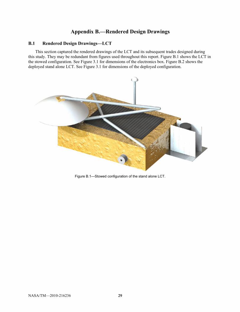
This section captured the rendered drawings of the LCT and its subsequent trades designed during this study. They may be redundant from figures used throughout this report. Figure B.1 shows the LCT in the stowed configuration. See Figure 3.1 for dimensions of the electronics box. Figure B.2 shows the deployed stand alone LCT. See Figure 3.1 for dimensions of the deployed configuration.
Figure B.1—Stowed configuration of the stand alone LCT.

NASA/TM—2010-216236 30 30
Figure B.2—Stand alone LCT in deployed configuration.

NASA/TM—2010-216236 31 31
B.2 Rendered Design Drawings—Integrated LCT
Figure B.3 shows the LCT integrated with the minimum ascent Habitat configuration in the stowed position. Now that the 10 m antenna dish is mounted on top of a boom and this boom collapses down in the stowed configuration with the antenna dish facing down. Figure B.3 and Figure B.4 show two views of the LCT integrated into the minimum ascent Habitat configuration in the deployed position. Note that the minimum ascent stage has departed from the lunar surface.
Figure B.3—Integrated LCT in stowed position on current mini-hab Lunar Lander.
Figure B.4—Integrated LCT in deployed position on current mini-hab Lunar Lander.
NASA/TM—2010-216236 32 32
Figure B.5—Integrated LCT in deployed position on current mini-hab Lunar Lander, side view.
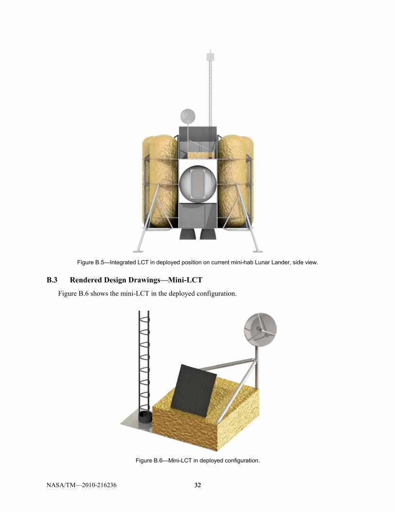
B.3 Rendered Design Drawings—Mini-LCT
Figure B.6 shows the mini-LCT in the deployed configuration.
Figure B.6—Mini-LCT in deployed configuration.

NASA/TM—2010-216236 33 33
Appendix C.—Study Participants
Lunar Communications Terminal (LCT) Design Session
Subsystem Name Center Email
LAT2 Comm and Nav Lead Jim Shier HQ [email protected]
LRS Customer Mark Flanegan GSFC [email protected]
Design Session Lead Steve Oleson GRC [email protected]
Communications Payload Interface (GRC) Joe Warner GRC [email protected]
Communications Sub team Lead (GRC) Lynn Anderson GRC [email protected]
System Integration, MEL and final report documentation Melissa McGuire GRC [email protected]
ELV, Integration and Test, Operations Jeff Woytach GRC [email protected]
Structures and Mechanisms Nelson Morales GRC [email protected]
Structures and Mechanisms John Gyekenyesi GRC [email protected]
Structures and Mechanisms Amy Stalker GRC [email protected]
Thermal Tony Colozza GRC [email protected]
Power Josh Freeh GRC [email protected]
Command and Data Handling Jeff Juergens GRC [email protected]
Communications Sub team (GRC) O. Scott Sands GRC [email protected]
Communications Sub team (GRC) Chuck Sheehe GRC [email protected]
Communications Consultant Dale Force GRC [email protected]
Communications Consultant Monte Andro GRC [email protected]
Communications Consultant Larry Foore GRC [email protected]
Communications Consultant Richard Lee GRC [email protected]
LRS Comm. interface Biren Shah JPL [email protected]
Configuration Tom Packard GRC [email protected]
Software TC Nguyen GRC [email protected]
Cost Tom Parkey GRC [email protected]
Risk/Reliability Anita Tenteris GRC [email protected]
Risk/Reliability Bill Strack GRC [email protected]

REPORT DOCUMENTATION PAGE Form Approved
OMB No. 0704-0188 The public reporting burden for this collection of information is estimated to average 1 hour per response, including the time for reviewing instructions, searching existing data sources, gathering and maintaining the data needed, and completing and reviewing the collection of information. Send comments regarding this burden estimate or any other aspect of this collection of information, including suggestions for reducing this burden, to Department of Defense, Washington Headquarters Services, Directorate for Information Operations and Reports (0704-0188), 1215 Jefferson Davis Highway, Suite 1204, Arlington, VA 22202-4302. Respondents should be aware that notwithstanding any other provision of law, no person shall be subject to any penalty for failing to comply with a collection of information if it does not display a currently valid OMB control number. PLEASE DO NOT RETURN YOUR FORM TO THE ABOVE ADDRESS.
1. REPORT DATE (DD-MM-YYYY) 01-12-2010
2. REPORT TYPE Technical Memorandum
3. DATES COVERED (From - To)
4. TITLE AND SUBTITLE COMPASS Final Report: Lunar Communications Terminal (LCT)
5a. CONTRACT NUMBER
5b. GRANT NUMBER
5c. PROGRAM ELEMENT NUMBER
6. AUTHOR(S) Oleson, Steven, R.; McGuire, Melissa, L.
5d. PROJECT NUMBER
5e. TASK NUMBER
5f. WORK UNIT NUMBER WBS 986249.01.11.20.22.03
7. PERFORMING ORGANIZATION NAME(S) AND ADDRESS(ES) National Aeronautics and Space Administration John H. Glenn Research Center at Lewis Field Cleveland, Ohio 44135-3191
8. PERFORMING ORGANIZATION REPORT NUMBER E-17223
9. SPONSORING/MONITORING AGENCY NAME(S) AND ADDRESS(ES) National Aeronautics and Space Administration Washington, DC 20546-0001
10. SPONSORING/MONITOR'S ACRONYM(S) NASA
11. SPONSORING/MONITORING REPORT NUMBER NASA/TM-2010-216236
12. DISTRIBUTION/AVAILABILITY STATEMENT Unclassified-Unlimited Subject Categories: 17, 18, and 91 Available electronically at http://gltrs.grc.nasa.gov This publication is available from the NASA Center for AeroSpace Information, 443-757-5802
13. SUPPLEMENTARY NOTES
14. ABSTRACT The Lunar Communications Terminal (LCT) COllaborative Modeling and Parametric Assessment of Space Systems (COMPASS) session designed a terminal to provide communications between lunar South Pole assets, communications relay to/from these assets through an orbiting Lunar Relay Satellite (LRS) and navigation support. The design included a complete master equipment list, power requirement list, configuration design, and brief risk assessment and cost analysis. The Terminal consists of a pallet containing the communications and avionics equipment, surrounded by the thermal control system (radiator), an attached, deployable 10-m tower, upon which were mounted locally broadcasting and receiving modems and a deployable 1 m diameter Ka/S band dish which provides relay communications with the lunar relay satellites and, as a backup, Earth when it is in view. All power was assumed to come from the lunar outpost Habitat. Three LCT design options were explored: a stand-alone LCT servicing the manned outpost, an integrated LCT (into the Habitat or Lunar Lander), and a mini-LCT which provides a reduced level of communication for primarily robotic areas dealing as in situ resource utilization (ISRU) and remote science. Where possible all the designs assumed single fault tolerance. Significant mass savings were found when integrating the LCT into the Habitat or Lander but increases in costs occurred depending upon the level of man rating required for such designs. 15. SUBJECT TERMS Lunar communication; Lunar satellites; Relay satellites; Telecommunication; Aerospace systems; Lunar bases
16. SECURITY CLASSIFICATION OF: 17. LIMITATION OF ABSTRACT UU
18. NUMBER OF PAGES
41
19a. NAME OF RESPONSIBLE PERSON STI Help Desk (email:[email protected])
a. REPORT U
b. ABSTRACT U
c. THIS PAGE U
19b. TELEPHONE NUMBER (include area code) 443-757-5802
Standard Form 298 (Rev. 8-98)Prescribed by ANSI Std. Z39-18