Comparison of Various Single-Ply Roof Covers for Fire...
8
T he use of controlled fire in do- mestic applications began ap- proximately 500,000 years ago. This ability to use fire allowed humans to move from the warm tropical areas of the world to the colder climates of Europe, Asia, and the western hemisphere. Fire provided a means to warm the living areas, cook food, and provide light. Fire was instrumen- tal in the development of everyday tools and goods from metals to pottery, which allowed for quicker advancement of mankind. As civilization moved forward, people started to develop densely populated cities, mostly for security reasons, often with individual buildings being connected or sharing com- mon walls. Typically, these structures had beams made from wood, and the roofs were thatch or similar organic material. Chim- neys were often generally short with large openings that allowed burning embers to travel to adjacent roofs, igniting the roofing and other materials. As one can imagine, with the lack of equipment or firefighting methods, fires in ancient cities were cata- strophic, often resulting in complete destruction of cities. In 1666, the Great Fire of London burned for five days, destroying approxi- mately two-thirds of the city and leaving over 200,000 people homeless. From this event, the first fire departments and fire insurance companies were founded. The fire led to the first recorded use of pumps to fight fires, ladders to be used for fire sup- pression and rescue, as well as fire insur- ance. New building laws stopped the use of timber; required brick, stone, or masonry construction; and widened the streets to limit the damage from flying burning embers. In essence, London enacted the first fire code for buildings. Fires were also very common in the early days of settlement in North America. In 1631, Boston banned the use of thatched roofs and wood chimneys after a serious fire; New York followed suit in 1648. After a devastating fire in 1653 in which a third of the families in Boston were left homeless, the city required every house to have a lad- der and a 12-foot-long pole with a wet swab to extinguish burning embers on the roofs. There were additional requirements and restrictions enacted by the city but to no avail, as the city was devastated at least five more times by massive fires. Throughout the 1700s and 1800s and into the first third of the 1900s, massive, devastating fires continued to plague cities, causing a tremendous loss of life as well as extremely costly property damage. The insurance industry, after massive fires and economic losses, was instrumental in the development of fire codes. One of the first fire codes used as a type of model code was developed by the national Board of Fire Underwriters, later renamed the American Insurance Association. After a number of fires with large loss of life, such as the infa- mous Triangle Building fire, the National Fire Protection Association (NFPA) began issuing pamphlets in the early 1900s describing the basic requirements for evac- uating or safely exiting buildings. These pamphlets led to the development of the NFPA Building Exit Code, later renamed the Life Safety Code. The safety codes, along with the insurance-driven codes, eventually became the foundation for what is current- ly used in the International Building Code (IBC), the model code developed by the International Code Council (ICC), which has been adopted throughout the country. The International Building Code covers fire pre- vention in regard to building construction and design in great detail, while the Inter- national Fire Code addresses fire issues concerning operations in a completed and occupied building. F EBRUARY 2012 I NTERFACE • 11
Transcript of Comparison of Various Single-Ply Roof Covers for Fire...
The use of controlled fire in do mes tic applications began ap proximately 500,000 years ago. This ability to use fire allowed humans to move from the warm tropical areas of the
world to the colder climates of Europe, Asia, and the western hemisphere. Fire provided a means to warm the living areas, cook food, and provide light. Fire was instrumental in the development of everyday tools and goods from metals to pottery, which allowed for quicker advancement of mankind. As civilization moved forward, people started to develop densely populated cities, mostly for security reasons, often with individual buildings being connected or sharing common walls. Typically, these structures had beams made from wood, and the roofs were thatch or similar organic material. Chim neys were often generally short with large openings that allowed burning embers to travel to adjacent roofs, igniting the roofing and other materials. As one can imagine, with the lack of equipment or firefighting methods, fires in ancient cities were catastrophic, often resulting in complete destruction of cities.
In 1666, the Great Fire of London burned for five days, destroying approxi
mately two-thirds of the city and leaving over 200,000 people homeless. From this event, the first fire departments and fire insurance companies were founded. The fire led to the first recorded use of pumps to fight fires, ladders to be used for fire suppression and rescue, as well as fire insurance. New building laws stopped the use of timber; required brick, stone, or masonry construction; and widened the streets to limit the damage from flying burning embers. In essence, London enacted the first fire code for buildings.
Fires were also very common in the early days of settlement in North America. In 1631, Boston banned the use of thatched roofs and wood chimneys after a serious fire; New York followed suit in 1648. After a devastating fire in 1653 in which a third of the families in Boston were left homeless, the city required every house to have a ladder and a 12-foot-long pole with a wet swab to extinguish burning embers on the roofs. There were additional requirements and restrictions enacted by the city but to no avail, as the city was devastated at least five more times by massive fires. Throughout the 1700s and 1800s and into the first third of the 1900s, massive, devastating fires continued to plague cities, causing a
tremendous loss of life as well as extremely costly property damage.
The insurance industry, after massive fires and economic losses, was instrumental in the development of fire codes. One of the first fire codes used as a type of model code was developed by the national Board of Fire Underwriters, later renamed the American Insurance Association. After a number of fires with large loss of life, such as the infamous Triangle Building fire, the National Fire Protection Association (NFPA) began issuing pamphlets in the early 1900s describing the basic requirements for evacuating or safely exiting buildings. These pamphlets led to the development of the NFPA Building Exit Code, later renamed the Life Safety Code. The safety codes, along with the insurance-driven codes, eventually became the foundation for what is currently used in the International Building Code (IBC), the model code developed by the International Code Council (ICC), which has been adopted throughout the country. The International Building Code covers fire prevention in regard to building construction and design in great detail, while the International Fire Code addresses fire issues concerning operations in a completed and occupied building.
F E B R U A R Y 2 0 1 2 I N T E R F A C E • 1 1

While fire, safety, and building codes in general have greatly improved over the years, losses from fire are still an ongoing issue. “In 2010, public fire departments responded to 1,331,500 fires in the United States,” according to estimates based on data NFPA received from fire departments responding to its 2010 National Fire Experience Survey. An estimated 482,000 structure fires were reported to fire departments in 2010.
Photo 1 – Burning brand.
The NFPA estimates that these fires caused nearly $11.6 billion in property damage. Fires in structures resulted in $9.7 billion in property damage. Of the reported fires, the NFPA estimates there were 3,120 civilian deaths, with the vast majority occurring in residential fires. In addition to the civilian deaths, an estimated 17,700 people were injured in fires during 2010. This is an approximate 3.9% increase from 2009 and the highest total since 2005.
(Information taken from the NFPA Journal, Sept./Oct. 2011, by Michael J. Karter, Jr.)
The information noted above from the NFPA reinforces the fact that while the frequencies of fires may be declining, there is still a tremendous impact due
to losses from fires. Building codes and insurance requirements have been developed and implemented with the intention of minimizing fire loss.
One of the most vulnerable components of a building when exposed to fire is the roof. Roof systems can burn from within the building or from the topside down. Fires from within are more complex, with a multitude of building systems that may influence the fire. External fires affecting the roof are generally simpler, as there are fewer components within the roof system. Codes require that roofing systems be tested and classified to meet certain requirements, depending on the building use and occupancy.
There have been various forms of fire codes and insurance requirements for fire protection since colonial times. What was lacking for construction materials – specifically roofing products – was a method to
Photo 2 – Intermittent flame.
Photo 3 – Spread of flame.
ͻ&ƌĞĞĂĐĐĞƐƐƚŽƚĞĐŚŶŝĐĂůĂƌƟĐůĞƐĨƌŽŵZ/ Ɛ/ŶƚĞƌĨĂĐĞƚĞĐŚŶŝĐĂůũŽƵƌŶĂů ͻŽǁŶůŽĂĚĚŽďĞĐƌŽďĂƚ;ƉĚĨͿĮůĞƐƚŽLJŽƵƌĐŽŵƉƵƚĞƌ ͻ<ĞLJǁŽƌĚͲƐĞĂƌĐŚĂďůĞǁŝƚŚ'ŽŽŐůĞ
1 2 • I N T E R F A C E F E B R U A R Y 2 0 1 2

test products when exposed to fire. It is believed that the first fire test for roofing products was developed by Underwriters Laboratories, Inc. (UL) in 1903. This UL test protocol standardized the evaluation of roof coverings’ ability to withstand ignition, flame spread, and fire penetration from external fires. In 1910, a new standard developed by the NFPA was adopted that set classifications for roof covers. This standard had three tests: flame exposure, burning brand, and a radiation exposure. The standard also included an investigation to determine the quality of the raw material, weathering, and reparability of the roof coverings as applied to the roof system. There were continuing adjustments and refinements to the fire test standards and reporting up to 1955, when ASTM Standard E108, Standard Test Methods for Fire Tests of Roof Coverings, was adopted. The last major changes were made to the standard between 1970 and 1975, mostly with regard to format and test criteria, which are the basis for the current version.
ASTM E108, which is essentially the same as UL 790 and NFPA 256, evaluates the relative fire characteristics of roof coverings when exposed to external fire sources.
There are three classifications defined in the standard: Class A, Class B, and Class C. The Class A rating is for roof coverings that can withstand severe test exposure, afford a high degree of protection to the roof deck, will not slip, and do not generate any flying brand or embers. Class B ratings are for roof covers that can withstand moderate test exposures, in that they afford a moderate degree of protection to the roof deck, will not slip, and do not generate any flying brand or embers. Class C ratings cover light test exposures and afford a light degree of protection to the roof deck, will not slip, and do not generate any flying brand or embers.
This test standard measures the ability of the roof covering to protect or resist fire from penetrating from the topside of the test deck to the underside. The roof fire penetration tests include the burning brand test (Photo 1) and the intermittent-flame-exposure test (Photo 2). The standard also measures the distance a flame can spread along the top surface, the spread-of-flame test (Photo 3), a nonpenetrating test. If the intent is to test a roof covering over a combustible-type roof deck, then all three tests are done. When the roof deck is noncombustible, such as concrete or steel, or if a combustible deck assembly uses a specific type
of gypsum board or similar approved thermal barrier, then only the spread-of-flame test is conducted.
The spread-of-flame test uses a constant flame source and a steady air movement to determine the potential for fire to spread across the surface of the roof cover. The maximum length allowed that still achieves a class A rating is six feet, class B is eight feet, and class C is 13 feet. In all cases, the fire cannot spread laterally to either edge of the test sample.
The main variables in the E108 test method are the components of the roof covering buildup and the slope of the deck. This test method provides a means for comparing roof-covering materials as tested according to the standard. There was some concern with the fire test standard as noted in the MRCA and NRCA report dated January 2006. Prior to this report, the MRCA and NRCA did a series of evaluations of aging on 109 polymer modified-bitumen roof systems. During the study, beginning in 1991, they realized fire resistance is an important attribute for roof covers. In 1996, the MRCA did a limited fire test program fol
lowing the spread-of-flame method from ASTM E108. Four of the roof systems from the study were tested, with half passing. Based on the results, the MRCA conducted additional fire tests on aged materials in 2001, again to see if aged roof systems maintained their listed fire classification or rating. In this study, ten samples were taken from five different roof-covering categories: coated modified bitumen, granular-surfaced modified bitumen, PVC, TPO, and EPDM. All systems were believed to have been installed as classified fire-rated systems. From this round of testing, five of the test decks passed the spread-of-flame tests: both PVC systems, one from each of the modified bitumens, and one EPDM.
In an effort to better understand the failure of the rated EPDM and TPO materials, the MRCA and NRCA conducted additional fire test evaluations, this time with new and aged systems using these membranes. They wanted to see if the aged roof-cover systems would maintain the listed fire classification, as well as verify that new roofcover systems would meet the listed ratings. This round of testing evaluated 34
F E B R U A R Y 2 0 1 2 I N T E R F A C E • 1 3

UL Fire Ratings, Class A Assemblies
EPDM
FR-Rated Membrane
TPO PVC Test
Slope
Isocyanurate 0.5/12 to 0.75/12 0.5/12 2/12 0.5/12
Gypsum board 4/12 to 5/12 3/12 5/12 3/12
Table 1
Graph 1 – Maximum spread of flames per membrane at two different slopes.
Graph 2
assemblies: eight new and ten existing EPDM membranes, and ten new and six aged TPO membranes. This round of testing used four different certified testing laboratories, which were instructed to test for spread of flame. Of the 34 test assemblies, only 13 passed or met the listed classification. Almost all of the test assemblies that passed (12 of the 13) included a cover board.
From this round of testing, more questions were raised, including the reproducibility of the test method between labs and within the same laboratory, the methods for constructing the test assemblies (how the edges are addressed), and how different labs interpret the results (lateral failure of just one or both sides).
ASTM Committee E05 is addressing the issues regarding test method E108, specifically with the construction of the test decks, interpreting the results, and adding a precision and bias statement to the document.
Given the results from the various fire test investigations by the MRCA and NRCA, we decided to conduct our own test program to compare the fire test properties of fire-retardant EPDM, PVC, and TPO membranes. We chose two of the most common substrates used with single-ply roof membranes: an ASTM C1289 Type II, Class 1, Grade 2, isocyanurate insulation board (organic black facer, 20 psi compressive strength) and a glass-faced gypsum board. The slope for the test program was determined after reviewing the classifications for each membrane type and substrate found in the UL Fire Directory. The highest slope for each type of membrane and board combination was charted. From this information, the lowest slope for the membrane and board combination was chosen.
For example, with gypsum board as the substrate, the greatest slope found in UL’s directory for the TPO membrane that
Gypsum Board – Slope 3/12 Isocyanurate – Slope 0.5/12
Membrane Max. Flame
Spread
Time to
Max. Flame
Class Max. Flame
Spread
Time to
Max. Flame
Class
EPDM FR-Rated
Membrane
67 in. 4:03 A 60 in. 2:30 No rating **
PVC 40 in. 0:54 A 40 in. 1:35 A
TPO 68 in. 8:18 A 67 in. 8:02 A
** Lateral spread-of-flame both to the right and left sides, starting 18 in. from the leading edge and proceeding for 24 in. Smoke generation was similar for all test frames.
Table 2
1 4 • I N T E R F A C E F E B R U A R Y 2 0 1 2

Photo 4 – FR-rated EPDM over listed gypsum board.
Photo 6 – PVC over listed gypsum board.
Photo 5 – TPO over listed gypsum board; very irregular flame pattern.
achieves a Class A rating is 3 in 12; for PVC, it was 5 in 12 at the time of the study. Similarly, the EPDM membrane over Dens Deck has a Class A rating of 5 in 12 for unreinforced adhered burned four times as long and the membrane, and 4 in 12 for rein- TPO membrane eight times as long forced mechanically attached as the PVC membrane with the gyp-membranes. Based on this sum substrate. Graph 2 illustrates information, all fire testing with the time differences among the memthe Dens Deck substrate was branes over each substrate. The conducted at a slope of 3 in 12. shorter the bar on the graph, the
Comparing UL Class A fire ratings with isocyanurate insulation as the substrate, the TPO membrane has a maximum slope of 0.5 inch in 12, the PVC is at 2 in 12, and the EPDM achieves a Class A at 0.5 inch in 12 for unreinforced adhered membranes and 0.75 inch in 12 for reinforced mechanically attached membranes. See Table 1.
Testing the three membranes to the noted slope-per-substrate allows for a direct comparison between the membranes and the specific board substrate, providing comparative information on how each membrane burns. All of the membranes were wrapped over the edges and secured to the wood side rails with roofing staples. The test method followed the ASTM E108 and UL 790 standard for spread of flame. The distance of the flame spread was recorded as well as the lateral distance every 12 in., beginning from the leading edge. The time of ignition, as well as the time to reach the maximum flame spread, were recorded. All testing was completed the same day and done by the same technician at the same laboratory. See Table 2.
Graph 1 shows the comparison among the three membranes’ flame spread for each substrate and tested slope combination (isocyanurate at 0.5 in. and DensDeck at 3 in.). The results show that the PVC membrane has a significantly lower flame spread, indicating that the membrane has a much greater resistance to spread of flame than the other membranes tested at the same conditions.
The time duration for the fire to reach the maximum flame spread was significantly shorter for the PVC membrane than either of the other membrane types for both substrates. Of important note, the flame on the PVC membrane did not sustain the fire; in essence, the membrane self-extinguished. The EPDM membrane
better the fire performance of the roof cover, as the system is not sus
taining the fire. The burn patterns for the PVC show a
very uniform triangular shape for both substrates (Photos 6 and 9). The TPO membrane has an elongated triangular shape with the gypsum substrate (Photo 5) and an
Photo 7 – FR-rated EPDM over isocyanurate, showing excessive lateral flame spread on both sides.
F E B R U A R Y 2 0 1 2 I N T E R F A C E • 1 5
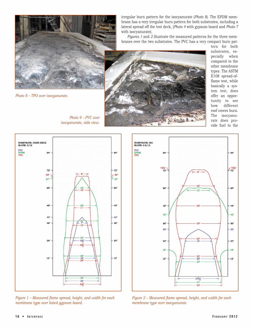
irregular burn pattern for the isocyanurate (Photo 8). The EPDM membrane has a very irregular burn pattern for both substrates, including a lateral spread off the test deck, (Photo 4 with gypsum board and Photo 7 with isocyanurate).
Figures 1 and 2 illustrate the measured patterns for the three membranes over the two substrates. The PVC has a very compact burn pat
tern for both sub strates, es pecially when compared to the other membrane types. The ASTM E108 spread-offlame test, while basically a system test, does offer an opportunity to see how different roof covers burn. The isocyanurate does provide fuel to the
Photo 8 – TPO over isocyanurate.
Photo 9 – PVC over isocyanurate, side view.
Figure 1 – Measured flame spread, height, and width for each membrane type over listed gypsum board.
Figure 2 – Measured flame spread, height, and width for each membrane type over isocyanurate.
1 6 • I N T E R F A C E F E B R U A R Y 2 0 1 2

test construction, which allows the fire to propagate as shown by the additional lateral spread of flame for all three membranes. When the roof covers are placed on the fire-resistant gypsum board, little to no fuel is added to the fire. This assembly provides a good idea of how well the roof membranes resist the spread of fire. The PVC roof cover has almost 60% better spread-of-flame resistance than the other membranes.
Another test method to show how different roof membranes perform when exposed to fire is a vertical strip fire test. With this test, samples of roof membrane cut at 75 mm (3 in.) wide by 170 mm (6.7 in.) long strips are fixed to a hanging device. A gas flame is placed in contact with the sample and left in place for 15 seconds, at which time the flame is removed. The test records the time for either the flame to extinguish or consume the sample.
An example of this test can be seen at www.vinylroofs.org/durability/vinyl-fireperformance/index.html. The test recorded on this Web site was conducted by South west Research Institute (SwRI) in San Antonio, TX. This test shows that the PVC membrane will self-extinguish within seconds of having the gas flame removed. Both
the EPDM and TPO membranes will burn until fully consumed. Similar to the spread-of-flame test deck with the gypsum substrate, this test shows how the different roof membranes react when ignited.
One of the strengths of a PVC roof membrane is its ability to “self-extinguish” and resist spreading the fire. There are documented events where the PVC roof membrane helped contain a fire and limit the
Photo 10 – Close-up of roof-mounted lighting system, Toyota Center, Houston, TX.
Photo 11 – Overview of roof-mounted lighting system. Fire
damage on left side, Toyota Center, Houston, TX.
amount of damage to the building, its occupants, and equipment. One example is the Ballantyne facility in Omaha, NE. The fire started at a heat stack and moved upward to the roof surface. According to Mike Connolly of D.C. Taylor company, the installing roofing contractor, the PVC roof membrane resisted spreading the fire, thus limiting damage to the exterior in the immediate vicinity of the stack.
F E B R U A R Y 2 0 1 2 I N T E R F A C E • 1 7

A roof-mounted lighting system at the Toyota Center, Houston, TX, short-circuited on a number of occasions, causing fires. The fires were never able to propagate across the surface of the PVC roof membrane, thereby limiting the damage and preventing a potentially dangerous situation from developing (see Photos 10 and 11).
Another example is a fire in North Bay, Ontario, where a PVC roof is credited for protecting a number of businesses from being destroyed. The fire started in the Motion Canada building and began spreading to other sections. The building owner (who acknowledged that the fire hydrants were not operative) and the fire department (which had little to no water to battle the fire) credit the PVC roof membrane for preventing the fire from spreading.
With the more common use of the rooftop as a platform for installing solar photovoltaic (PV) systems, there is also an increased possibility of a rooftop electrical fire. Fires that may result from rooftop PV installations present unique and dangerous challenges to firefighters due to the fact that the PV panels continue to generate electricity as long as they are exposed to sunlight, increasing the risk of rapid spread of fire across the underlying roof surfaces. With their superior ability to minimize the spread of flame and to self-extinguish, PVC membranes provide important life safety benefits on roofs upon which PV arrays are to be installed.
SUMMARY Building codes, including fire safety
codes, continue to evolve and provide additional security for building occupants. While tremendous strides have been made in reducing fires and the resultant property damage, injuries, and deaths, the construction industry should work to continually improve these areas through better construction practices. As part of the building industry, roofing specifiers and contractors must take fire safety seriously in design and specifications. Specified roof systems should, at a minimum, be tested and listed assemblies with one of the certified testing agencies approved by the building code. However, they must be mindful that specifying to a minimum standard is not necessarily in the best interests of the building owner. Testing by various sources has shown that there is a significant performance difference among various roof membrane types.
REFERENCES Jim Arnold, “Large Building Fires and
Subsequent Code Changes,” NFPA, 2005.
Michael J. Karter, Jr., “Fire Loss in the United States During 2010,” NFPA Journal, Sept./Oct. 2011.
ASTM E108, “Standard Test Methods for Fire Tests of Roof Coverings,” 2011.
Fire Testing of Membrane Roof Systems, MRCA, NRCA, 2006.
Southwest Research Institute, final report, “Fire Test Evaluation in General Accordance With SIA Test Method V280/12 (1996), Vertical Burn Test,” 2006.
S. P. Graveline, “Sustainability of Thermoplastic Vinyl Roofing Membrane Systems,” IC-Best Symposium, 2011.
Joe Schwetz
Joe Schwetz is the national technical manager for Sika Sarnafil, a division of Sika Corp., Canton, MA. He has worked in the roofing industry for over 25 years in various research and development, technical, and managerial capacities. He is active in various technical standards and code development bodies and chairs the ASTM committee on PVC roofing.
1 8 • I N T E R F A C E F E B R U A R Y 2 0 1 2