COMPARISON OF STRUCTURAL STEEL LATERAL FORCE RESISTING ... · The lateral force resisting system is...
81
COMPARISON OF STRUCTURAL STEEL LATERAL FORCE RESISTING SYSTEMS FOR A THEORETICAL HOSPITAL GRID SYSTEM by GRANT BUELL B.S., Kansas State University, 2009 A REPORT submitted in partial fulfillment of the requirements for the degree MASTER OF SCIENCE Department of Architectural Engineering and Construction Science College of Engineering KANSAS STATE UNIVERSITY Manhattan, Kansas 2009 Approved by: Major Professor Professor Kimberly Waggle Kramer, P.E.
Transcript of COMPARISON OF STRUCTURAL STEEL LATERAL FORCE RESISTING ... · The lateral force resisting system is...

COMPARISON OF STRUCTURAL STEEL LATERAL FORCE RESISTING SYSTEMS FOR
A THEORETICAL HOSPITAL GRID SYSTEM
by
GRANT BUELL
B.S., Kansas State University, 2009
A REPORT
submitted in partial fulfillment of the requirements for the degree
MASTER OF SCIENCE
Department of Architectural Engineering and Construction Science College of Engineering
KANSAS STATE UNIVERSITY Manhattan, Kansas
2009
Approved by:
Major Professor Professor Kimberly Waggle Kramer, P.E.

Copyright
GRANT BUELL
2009

Abstract
In 2006, a research project was being carried out by architects at architecture/engineering
firm Cannon Design involving an optimum bay size for a hospital. RISA computer modeling was
used to explore a set of lateral force resisting system (LFRS) options for a building based on this
optimum bay size and importance category. The structural material was first narrowed down to
steel, and then moment frames and braced frames are examined. The LFRS was narrowed down
to braced frames, discarding moment frames due to their inordinate story drift. Of the different
types of braced frames, the study further narrowed the LFRS system to chevron braced frames.
Then the precise arrangement of braces for a particular building size using this bay system was
examined. The steel material cost of the final system was compared to a system that only
included members sized for gravity loads to demonstrate the rough amount of cost that a lateral
system can add to a building.

iv
Table of Contents
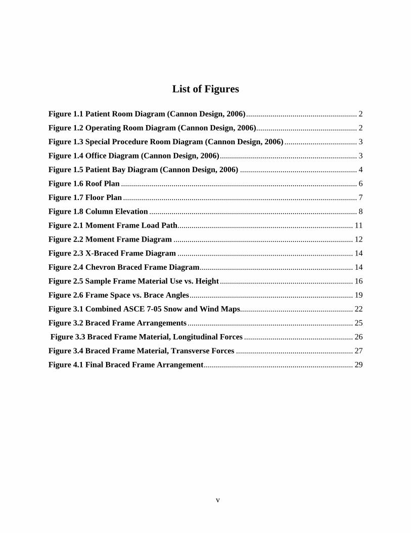
List of Figures ................................................................................................................................. v
List of Tables ................................................................................................................................. vi
CHAPTER 1 - The Hospital Grid System ...................................................................................... 1
Architectural Purpose ................................................................................................................. 1
Criteria ........................................................................................................................................ 1
Dimensions ................................................................................................................................. 4
Variables ..................................................................................................................................... 5
CHAPTER 2 - Discussion of Lateral Force Resisting System Structural Issues ......................... 10
Lateral Force Resisting Systems ............................................................................................... 10
Moment Frames .................................................................................................................... 11
Braced Frames ...................................................................................................................... 13
Frame System Comparison ................................................................................................... 15
CHAPTER 3 - ANALYSIS AND CALCULATIONS ................................................................. 20
Building Size ............................................................................................................................. 20
Gravity Loads ........................................................................................................................... 21
Gravity Member Sizes .............................................................................................................. 22
Wind Loads ............................................................................................................................... 23
Lateral Member Sizes ............................................................................................................... 24
Cost Analysis ............................................................................................................................ 27
CHAPTER 4 - CONCLUSIONS .................................................................................................. 28
References ..................................................................................................................................... 30
Appendix A - Gravity Load Calculations ..................................................................................... 31
Dead Load ................................................................................................................................. 31
Live Load .................................................................................................................................. 32
Snow Load ................................................................................................................................ 34
Appendix B - Gravity Member Sizing Calculations ..................................................................... 35
Appendix C - Wind Load Calculations ......................................................................................... 66
Appendix D - Permissions ............................................................................................................ 75
v
List of Figures
Figure 1.1 Patient Room Diagram (Cannon Design, 2006) ....................................................... 2
Figure 1.2 Operating Room Diagram (Cannon Design, 2006) .................................................. 2
Figure 1.3 Special Procedure Room Diagram (Cannon Design, 2006) .................................... 3
Figure 1.4 Office Diagram (Cannon Design, 2006) .................................................................... 3
Figure 1.5 Patient Bay Diagram (Cannon Design, 2006) .......................................................... 4
Figure 1.6 Roof Plan ..................................................................................................................... 6
Figure 1.7 Floor Plan .................................................................................................................... 7
Figure 1.8 Column Elevation ....................................................................................................... 8
Figure 2.1 Moment Frame Load Path....................................................................................... 11
Figure 2.2 Moment Frame Diagram ......................................................................................... 12
Figure 2.3 X-Braced Frame Diagram ....................................................................................... 14
Figure 2.4 Chevron Braced Frame Diagram ............................................................................ 14
Figure 2.5 Sample Frame Material Use vs. Height .................................................................. 16
Figure 2.6 Frame Space vs. Brace Angles ................................................................................. 19
Figure 3.1 Combined ASCE 7-05 Snow and Wind Maps........................................................ 22
Figure 3.2 Braced Frame Arrangements .................................................................................. 25
Figure 3.3 Braced Frame Material, Longitudinal Forces ...................................................... 26
Figure 3.4 Braced Frame Material, Transverse Forces .......................................................... 27
Figure 4.1 Final Braced Frame Arrangement .......................................................................... 29

vi
List of Tables
Table 1.1 Roof/Floor Plan Labeling Scheme .............................................................................. 8
Table 1.2 Column Elevation Labeling Scheme........................................................................... 9
Table 2.1 Sample Frame Member Sizes .................................................................................... 18
Table 3.1 Gravity Member Sizes ............................................................................................... 23
Table 3.2 Case 1 Wind Loads: Longitudinal, Transverse Forces Applied Separately ......... 24

1
CHAPTER 1 - The Hospital Grid System
In summer 2006, the structural engineering division at the St. Louis office of Cannon
Design, an architecture and engineering firm with 13 offices worldwide, worked closely with the
architecture department on several research initiatives. One of these was based on exploring the
concept of creating a prototypical hospital bay. This is referred to as a universal grid. This report
will explore a set of structural design issues relating to designing a building with this universal
grid – specifically, it will analyze a group of lateral force resisting systems and determine the
best one for this application. This section will explore this project’s purpose, the criteria used in
the project, the dimensions determined by these criteria and possible building variations that can
affect this system.
Architectural Purpose The purpose of the universal grid is to maximize design efficiency as well as space use
flexibility for a variety of applications. The benefits of such a grid include the reduction of
design time and cost through the repetition of design elements. Architects will be able to use the
universal grid as a starting point for their designs (Cannon Design 8).
Criteria According to Cannon Design architect Natalie Petzoldt, the primary criteria for
determining the properties of the universal grid were American Institute of Architects clearance
requirements for various hospital spaces and pieces of equipment. A standardized bay size for a
hospital floor giving the required clearance between walls for a variety of space applications,
such as patient rooms, operating rooms, special procedure rooms, offices and others was the goal
(Petzoldt, 2006). Within this standardized bay size, the structural columns should fit within the
walls - the wall clearances required dictate the column spacing in the structural grid. The
structural design of the LFRS carried out in this report uses a lateral drift limit of frame
height/400 (h/400), which does not consider the interaction between the structural system and the
exterior cladding, whether it be glass, masonry or any other material. The architects at Cannon
determined the optimum bay size to be 31.5 feet by 31.5 feet (Cannon Design 9). Figures 1.1,

2
1.2, 1.3, 1.4 and 1.5 show various space applications considered for the grid system, and how
these applications fit in the 31.5 foot bays.
Figure 1.1 Patient Room Diagram (Cannon Design 13)
Figure 1.2 Operating Room Diagram (Cannon Design 14)

3
Figure 1.3 Special Procedure Room Diagram (Cannon Design 15)
Figure 1.4 Office Diagram (Cannon Design 16)

4
Figure 1.5 Patient Bay Diagram (Cannon Design 17)
Dimensions For this report, computer building models were constructed using a 31.5 foot by 31.5 foot
bay throughout the structure. In addition to a standard bay width and length, a standard vertical
dimension (floor-to-floor height) was required in the universal grid system. A standard floor-to-
floor height is more difficult to determine, as different types of spaces could require vastly
different amounts of plenum room for mechanical equipment while the depth required for the
structural system would stay approximately constant. The Cannon architects have proposed an
18 foot floor-to-floor height as a starting point (Cannon Design 9). This number is generous for
the mechanical plenum space and therefore, conservative for structural design. Structurally, an
18 foot floor-to-floor height is considered difficult to engineer cost effectively. The high floor-to-
floor height results in high slenderness of the structural frames, which puts a strain on their
ability to transfer the lateral load while minimizing story drift, especially when using moment
frames. The higher up the lateral load is, the larger the resulting moment going into the frame,
5
and in order for the frame to distribute the load, the moment needs to be resolved into a couple
force at the supports. The closer together these supports are, the higher the couple forces will
have to be. Thus, the higher up the lateral load point is, and the closer together the supports are,
the more the frame is loaded. This ratio of frame height to frame width is the “slenderness” of
the frame.
The roof and floor plans used for the models in this report are shown in Figures 1.6 and
1.7. Figure 1.6 shows the structural roof plan for the hospital model. It consists of structural steel
beams and open-web roof joists for the roof system arranged on the standard uniform hospital
grid of 31.5 feet by 31.5 feet. Figure 1.7 depicts the structural floor plan, composed of similar
structural elements but with tighter joist spacing due to higher floor live loads. Table 1.1 explains
the meanings of the beam and joist labels used in the models.
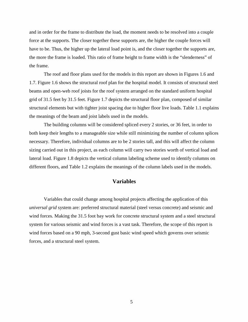
The building columns will be considered spliced every 2 stories, or 36 feet, in order to
both keep their lengths to a manageable size while still minimizing the number of column splices
necessary. Therefore, individual columns are to be 2 stories tall, and this will affect the column
sizing carried out in this project, as each column will carry two stories worth of vertical load and
lateral load. Figure 1.8 depicts the vertical column labeling scheme used to identify columns on
different floors, and Table 1.2 explains the meanings of the column labels used in the models.
Variables
Variables that could change among hospital projects affecting the application of this
universal grid system are: preferred structural material (steel versus concrete) and seismic and
wind forces. Making the 31.5 foot bay work for concrete structural system and a steel structural
system for various seismic and wind forces is a vast task. Therefore, the scope of this report is
wind forces based on a 90 mph, 3-second gust basic wind speed which governs over seismic
forces, and a structural steel system.

6
Figure 1.6 Roof Plan

7
Figure 1.7 Floor Plan

8
Table 1.1 Roof/Floor Plan Labeling Scheme
RJ1 Roof Joists RB1 Interior Roof Beams (Joist Bearing) RB2 Interior Roof Beams (Non Joint Bearing) RB3 Exterior Roof Beams (Joist Bearing) RB4 Exterior Roof Beams (Non Joist Bearing) FJ1 Floor Joists FB1 Interior Floor Beams (Joist Bearing) FB2 Interior Floor Beams (Non Joist Bearing) FB3 Exterior Floor Beams (Joist Bearing) FB4 Exterior Floor Beams (Non Joist Bearing C1 Exterior Column Line (Building Corners) C2 Exterior Column Line (Long Building Face) C3 Exterior Column Line (Short Building Face C4 Interior Column Line
Figure 1.8 Column Elevation
9
Table 1.2 Column Elevation Labeling Scheme
C1-1 Exterior Column (Building Corners), Floors 9 and 10 C1-2 Exterior Column (Building Corners), Floors 7 and 8 C1-3 Exterior Column (Building Corners), Floors 5 and 6 C1-4 Exterior Column (Building Corners), Floors 3 and 4 C1-5 Exterior Column (Building Corners), Floors 1 and 2 C2-1 Exterior Column (Long Building Face), Floors 9 and 10 C2-2 Exterior Column (Long Building Face), Floors 7 and 8 C2-3 Exterior Column (Long Building Face), Floors 5 and 6 C2-4 Exterior Column (Long Building Face), Floors 3 and 4 C2-5 Exterior Column (Long Building Face), Floors 1 and 2 C3-1 Exterior Column (Short Building Face), Floors 9 and 10 C3-2 Exterior Column (Short Building Face), Floors 7 and 8 C3-3 Exterior Column (Short Building Face), Floors 5 and 6 C3-4 Exterior Column (Short Building Face), Floors 3 and 4 C3-5 Exterior Column (Short Building Face), Floors 1 and 2 C4-1 Interior Column, Floors 9 and 10 C4-2 Interior Column, Floors 7 and 8 C4-3 Interior Column, Floors 5 and 6 C4-4 Interior Column, Floors 3 and 4 C4-5 Interior Column, Floors 1 and 2
10
CHAPTER 2 - Discussion of Lateral Force Resisting System
Structural Issues
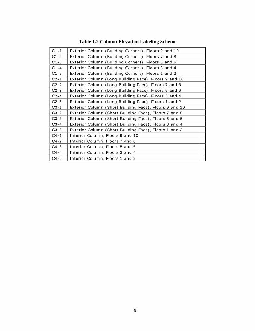
The basic framework of the universal grid – a 31.5 foot by 31.5 foot bay size, with an 18
foot floor-to-floor height – is used to explore the structural design implications for a steel
structural system for a building with wind-governed lateral forces. The lateral force resisting
system is the focus of this report, and the gravity system will be largely left undefined, as its
effect upon the performance of the lateral system members is minimal. The diaphragm assumed
for this building is steel deck with concrete fill, which will probably act as a rigid diaphragm, but
the symmetric loading and building layout considered in this report will result in the same load
distribution as a flexible diaphragm. The theoretical hospital is ten stories high and four bays
wide by eight bays long in plan.
This chapter of the report will focus on narrowing down the available LFRS choices by
considering isolated vertical frames using different LFRS types and applying unit loads to them
to compare their performance and efficiency. The actual building model will be analyzed in
chapter 3.
Lateral Force Resisting Systems A continuous load path for lateral loads is required for any structure to be stable. The
stability of the structure to resist wind horizontal forces and distribute these forces into the
supporting soil is in the lateral force resisting system. The lateral force resisting system consists
of two separate but integrally connected components of the structure – the diaphragm (horizontal
elements) and the frames or shear walls (vertical elements). The frames or shear walls behave as
cantilevers subjected to lateral loads. Frames may be braced or rigid (moment-resisting). Braced
frames resist lateral loads by truss action in the vertical plane. Rigid frames resist lateral loads by
the virtue of the moment-resisting joints. For a structural steel building, two lateral force
resisting systems are common – moment-resisting frames and braced frames. Variations on these
systems abound; for example, special moment resisting frames differ from ordinary moment
resisting frames in their connection quality, and braced frames come in a variety of shapes, such
as inverted V braces (also known as chevron braces) and X braces. See figures 2.3 and 2.4 for
illustrations of these braced frames.

11
Moment Frames A moment frame is a lateral force resisting system consisting of members designed to
carry the flexural forces induced by lateral loads, as well as the axial forces. The connections
between these members are considered to be “fixed,” which indicates the ability of the
connection to transfer bending forces between members. Resistance to lateral loads is provided
primarily by the flexural resistance of columns, girders and rotation of beam-column joints. If a
member bends at one end, the fixed connection is considered to bend along with the member so
that the angle between members remains constant (for a fully fixed connection). Figure 2.1
shows the deflection and load transfer through a moment frame.
Figure 2.1 Moment Frame Load Path
The level of “fixity” of the connection can vary between “fully fixed” and “partially
fixed” connections. For this report, fully fixed moment frame connections are examined. Refer to
Figure 2.2 for a multi-story diagram of the type of moment frames used. The solid triangular

12
symbol in the upper corners of the frame indicates a fixed connection that can transfer moment
as well as axial loads. The connections between the lower ends of the columns and the ground
are also fixed.
Figure 2.2 Moment Frame Diagram
A moment frame by definition is unbraced: horizontal displacement of the frame is
allowed when loaded laterally, and the columns are subjected to sidesway. The ability of moment
frame members and connections to bend allows for a certain level of “drift” (horizontal
displacement of the upper nodes) to occur. When a lateral force is applied to the top of a moment
frame, the columns bend as the top of the frame deflects in the direction of the applied load.
Because of the fixity of the connections, this deflection forces rotation in the connections in
order for the angles between the members to be maintained. This transfers load into the upper
beam of the moment frame axially, and shears are induced in the tops of the columns. The
rigidity of the connections causes the members to bend in reverse curvature as these loads are
transferred. As the members bend, the top of the frame can shift substantially, depending on the
members, the connections and the forces. Orienting the members so as to force the bending to
occur about the major axis can decrease the deflections of the members. The ratio of the distance

13
a frame deflects laterally under a given lateral load to the height of the frame is the “story drift
ratio,” and this is an important value to consider in the serviceability design of a building. High
moment frame deflections can have a variety of negative effects on buildings. For example, they
can damage glass, masonry and other building materials supported by the frames. They can also
induce P-delta effects - additional moments induced by loads being applied at a distance from
member axes due to deflection. For example, when a frame deflects, vertical loads that had
originally been along the column axes can move off the axes due to the lateral movement of the
upper part of the frame, and this can put additional bending moments into the frame.
The primary advantage to a moment frame is architectural – the area within a frame
consisting simply of two columns and a beam is clear of structural members. This gives the
architect a great deal of flexibility in his or her use of that space.
Braced Frames Braced frames resist lateral loads by truss action (axial loads) in the vertical plane.
Braced frames are comprised of horizontal members (beams or girders), vertical members
(columns) and inclined members (braces), which are not present in moment frames. The joints
between beams, columns and braces are flexible and assumed pin-connected theoretically. This
allows rotation at the beam-column joint. Since the beam-column joints are unable to resist
rotation in order to transfer lateral loads, the frame would be unstable without the presence of the
braces. The beams, columns and braces form a vertical truss configuration and are analyzed as a
vertical truss. The braces tend to prevent the columns from swaying. Because the joints of braced
frames are not designed to carry moment, all the forces in braced frames are transmitted through
the structure in the form of axial loads – tension and compression. Steel is extremely resistant to
tensile forces in comparison to other structural materials, and braced frames are an attractive
option for redirecting lateral loads. Two primary advantages of braced frame systems over
moment frame systems are the simplicity of their connections and the increased resistance to
story drift. In general, a braced frame is far stiffer than a moment frame with similar dimensions
and member sizes. To demonstrate the differences between the different frame systems, I
modeled a sample 31.5 foot x 18 foot frame from my hospital system as a moment frame (with
fully fixed upper and lower end connections), an X-braced frame (once with braces designed to

14
take tension forces only, and once with braces designed to take tension and compression forces),
and a chevron braced frame. See Figures 2.3 and 2.4 for the two braced frames.
Figure 2.3 X-Braced Frame Diagram
Figure 2.4 Chevron Braced Frame Diagram

15
Frame System Comparison A horizontal load of 10 kips was applied to the top of each single-story frame in the plane
of the frame (in each direction). The size of the load is an arbitrary figure chosen to give a
comparable set of displacement results between the different frame systems. After designing the
steel members of all the frames for strength requirements, as well as a maximum lateral drift
requirement of h/400 (Minimum Design Loads for Buildings and Other Structures 2002 366),
which is .54 inches for the universal grid height of 18 feet, the chevron braced frame turned out
to be the most economical option. The chevron braced frame required 1800 pounds of steel in a
single story frame, while 3200 pounds of steel were required for the moment frame. The X-
braced frame required 1900 pounds of steel when the braces were designed to take tension only,
and 2000 pounds of steel when the braces were designed to take tension and compression forces.
The moment frame required such a large amount of steel because it was heavily governed by
drift – it could satisfy the strength requirements alone with much smaller members, but the
lateral drift was much larger than the h/400 serviceability requirement. In order to drastically
reduce the lateral deflection, much stiffer members were needed. The braced frames, however,
each required little or no adjustment once designed for strength requirements – they were
naturally able to fulfill the horizontal drift requirements without increasing the member stiffness.
Each braced frame uses almost the same amount of material to resist the 10 kip load.
16
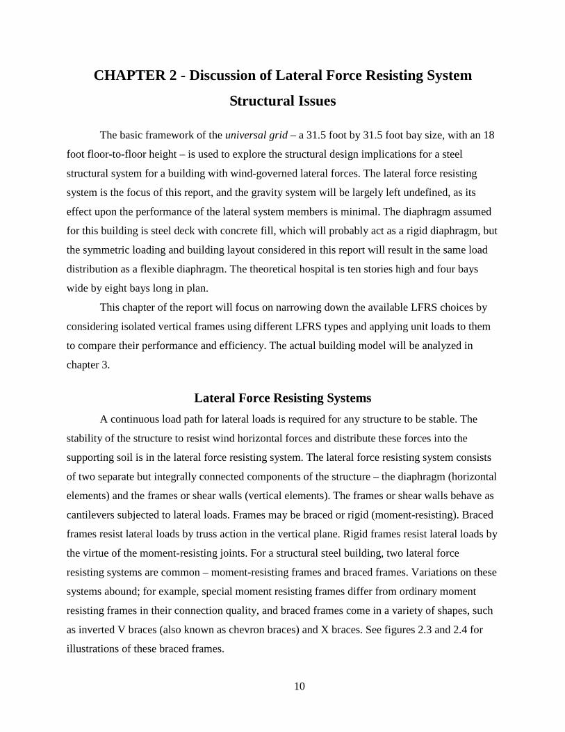
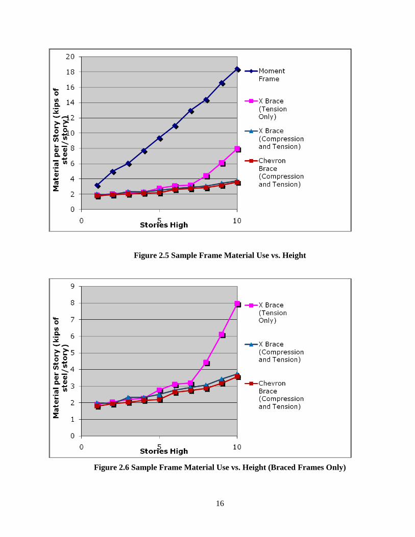
Figure 2.5 Sample Frame Material Use vs. Height
Figure 2.6 Sample Frame Material Use vs. Height (Braced Frames Only)

17
To provide a more comprehensive demonstration, additional models with similar frames
were examined which varied from one to ten vertical stories. For each iteration, a 10 kip
horizontal load at each story was used to provide a simple comparison between the performances
of the different lateral bracing systems. In order to simplify the design and make it more realistic,
column sizes were limited to W14 members and shallower, and beam sizes were limited to W30
members or shallower. The results for basic material efficiency (steel required per floor) are
shown in Figures 2.5 and 2.6. The braced frames use the least amount of steel, as their member
sizes are all governed by strength requirements – once these requirements are met, their lateral
drift turned out to be lower than the maximum allowable of .54 inches per story, and no resizing
was required. The percentage of actual drift to allowable drift started as low as 1-2% for a small
number of stories, and increased to 75-85% for large numbers of stories. The exception to this
pattern is in the X-braced frames with tension-only braces. Starting at about 8 stories, the
member sizes of these braced frames are governed by drift rather than strength, and the material
efficiency curve of the tension-only X-braced frames begins to parallel that of the moment
frames. Moment frames perform less efficiently in comparison at all heights, as the member
sizing of the moment frames are governed by drift, rather than strength, at all frame heights. The
optimum member sizes for all frames at all heights, determined with the aid of RISA 3D, can be
seen in Table 2.1.

18
Beam Sizes
Column Sizes
Brace SizesMaterial Takeoff
(thousands of lbs of steel/story)
Beam Sizes
Column Sizes
Brace SizesMaterial Takeoff
(thousands of lbs of steel/story)
1 W14x48 W14x48 n/a 3.2 W6x20 W8x24 HSS4x4x1/8 1.9
2 W30x90 W14x61 n/a 5 W8x24 W8x24 HSS4x4x1/8 2.05
3 W30x90 W14x90 n/a 6.07 W8x28 W8x24 HSS4x4x1/8 2.2
4 W30x108 W14x120 n/a 7.73 W8x31 W8x24 HSS4x4x1/8 2.275
5 W30x116 W14x159 n/a 9.38 W8x31 W14x38 HSS4x4x1/8 2.78
6 W30x148 W14x176 n/a 11 W8x35 W14x38 HSS4x4x3/16 3.12
7 W30x191 W14x193 n/a 12.97 W8x31 W14x38 HSS4x4x1/4 3.19
8 W30x191 W14x233 n/a 14.4 W10x54 W14x53 HSS4x4x1/4 4.44
9 W30x261 W14x233 n/a 16.61 W14x74 W14x82 HSS4x4x1/4 6.12
10 W30x261 W14x283 n/a 18.43 W18x76 W14x132 HSS4x4x1/4 7.97
Beam Sizes
Column Sizes
Brace SizesMaterial Takeoff
(thousands of lbs of steel/story)
Beam Sizes
Column Sizes
Brace SizesMaterial Takeoff
(thousands of lbs of steel/story)
1 W6x15 W8x24 HSS5.5x5.5x1/8 2 W6x20 W8x24 HSS4x4x1/8 1.8
2 W6x15 W8x24 HSS5.5x5.5x1/8 1.95 W8x24 W8x24 HSS4.5x4.5x1/8 1.95
3 W6x15 W8x24 HSS6x6x3/16 2.33 W8x24 W8x24 HSS5.5x5.5x1/8 2.03
4 W6x15 W8x24 HSS6x6x3/16 2.33 W8x28 W8x24 HSS5.5x5.5x1/8 2.15
5 W6x15 W8x24 HSS7x7x3/16 2.5 W8x28 W8x24 HSS6x6x1/8 2.2
6 W6x15 W8x31 HSS7x7x3/16 2.75 W8x31 W8x28 HSS6x6x3/16 2.63
7 W6x15 W8x31 HSS8x8x3/16 2.93 W8x31 W8x31 HSS6x6x3/16 2.74
8 W6x15 W8x35 HSS8x8x3/16 3.06 W8x31 W8x31 HSS8x6x3/16 2.86
9 W6x15 W10x45 HSS8x8x3/16 3.43 W8x31 W8x40 HSS8x6x3/16 3.18
10 W6x15 W10x54 HSS8x8x3/16 3.74 W8x31 W8x48 HSS8x8x3/16 3.58
Number of
Stories
Moment Frames X-Braced Frames (Tension Braces Only)
Number of
Stories
X-Braced Frames (Compression and Tension Braces) Chevron Braced Frames
Table 2.1 Sample Frame Member Sizes
The drawback to using braced frames is purely architectural – the area available beneath
the braces in the frame decreases the closer the frame is to an X-braced frame (that is, the larger
the angle is between the columns and the braces). Generally, the space beneath the braces is the
space available for people and equipment to move freely through, though the space above the
braces may be architecturally useful for other purposes, such as windows. See Figure 2.7 for the
relationship between the brace angle in a frame and the available area beneath the braces in the
frame.

19
Based on the results of these analyses, moment frames are discarded as an option for the
full building lateral system. Moment frames undergo lateral drifts far higher than braced frames,
especially for buildings as tall as 10 stories, such as my theoretical hospital model. The moment
frames required large increases in member sizes to meet drift requirements, and subsequently,
the material efficiency of the moment frames suffered greatly, as is evident in Figure 2.5. The
most efficient lateral system considered in terms of both strength and story drift is the chevron
braced frame. The chevron braced frame also has greater available space beneath its braces than
the X-braced frame. As a result of these analyses, the chevron braced frame is exclusively used
in the full building model.
Figure 2.7 Frame Space vs. Brace Angles
0
100
200
300
400
500
600
0 10 20 30 40 50 60 70 80 90 100
Brace Angle (Degrees)
Surface AreaMoment Frame
X-Braced Frame
Chevron Braced Frame
20
CHAPTER 3 - ANALYSIS AND CALCULATIONS
The structural analysis calculations for the full building model have been done with the
aid of RISA 2D software. The configuration and dimensions of the hospital layout are shown in
Figures 1.6, 1.7 and 1.8. The general analysis procedure consisted of the following steps:
i. Determine a theoretical building size. ii. Calculate basic assumed gravity loads that would apply to many hospital
building spaces. iii. Determine minimum member sizes based on these gravity loads. iv. Determine wind loads for an area with average wind speeds. v. Model lateral force resisting as chevron braced frames and size members
to take the calculated wind loads. vi. Estimate material cost for any feasible building designs determined by the
analysis.
Each of these steps is presented in detail in the following sections.
Building Size A 4 bay by 8 bay, 10 level building was analyzed. This gives a fairly large hospital to
analyze, but it is not so large that it needs to be separated into two separate structures by
construction joints. If the floor and roof diaphragms had to span too large a distance, their
structural performance would suffer. When a diaphragm taking lateral load is very wide (parallel
to the load) compared to its “depth” (perpendicular to the load), it is like a long shallow beam –
the moment increases with length, and the couple forces generated in the chords required to
resolve the moment are large due to the short distance between them. With 31.5 foot bays, 4 bays
by 8 bays means a 126 foot by 252 foot building, which was pushing the acceptable boundary of
a single diaphragm span. It was important to analyze a large building, however, as the point of
the universal grid is to streamline the design of large hospitals by eliminating design variations
between different areas. The 2 to 1 ratio of the building’s length to its width is based upon
Cannon Design case studies, which base their room layouts upon an approximately 2 to 1 floor
plan ratio.

21
Gravity Loads In order to determine minimum member sizes for the building’s beams and columns,
gravity loads were applied to them and they were sized based upon LRFD strength criteria and a
maximum total deflection criteria of L/240 (International Building Code 280). The gravity loads
applied to the building are as follows:
Roof dead load = 20 psf (pounds per square foot)
Roof live load = 20 psf
Roof snow load = 24 psf
Floor dead load = 60 psf
Floor live load = 100 psf
Wall dead load = 10 psf
These loads are based on a location of Chicago, Illinois, and the Minimum Design Loads
for Buildings and Other Structures 2005. See Appendix A for the calculations determining these
loads. The live load reduction provisions to reduce live loads for certain members with large
tributary areas were used (Minimum Design Loads for Buildings and Other Structures 2005 10).
Chicago has a ground snow load of 25 psf (85) and a wind speed of 90 mph (33). Figure
3.1 combines the Minimum Design Loads for Buildings and Other Structures 2005 wind and
snow load maps of the United States to show the areas where loads of these magnitudes or lower
would apply. The purple area of the map is the area that these load assumptions could apply to.
However, high seismic areas such as California would usually not use wind as a governing
lateral case. Figure 3.1 does not account for seismic loads that would govern over a 90 mph wind
speed.

22
Figure 3.1 Combined ASCE 7-05 Snow and Wind Maps
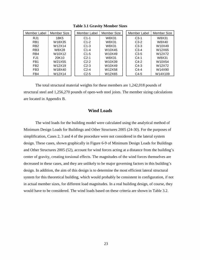
Gravity Member Sizes The minimum member sizes based on these gravity loads are contained in Table 3.1.
(Refer to Figures 1.6, 1.7 and 1.8 for identification of each member label.) LRFD strength
criteria were used to determine these member sizes, along with live load deflection criteria of
L/240 for the beams (International Building Code 280). (Total load deflection criteria, given in
the IBC as L/180, was not considered because the IBC allows dead load for steel structures to be
considered as zero when determining deflections. This reduces the total load deflection to live
load deflection only, and the L/240 criteria governs over L/180).
23
Table 3.1 Gravity Member Sizes
Member Label Member Size Member Label Member Size Member Label Member Size RJ1 18K5 C1-1 W8X31 C3-1 W8X31 RB1 W18X35 C1-2 W8X31 C3-2 W8X40 RB2 W12X14 C1-3 W8X31 C3-3 W10X49 RB3 W8X28 C1-4 W10X45 C3-4 W12X65 RB4 W10X12 C1-5 W10X49 C3-5 W12X72 FJ1 20K10 C2-1 W8X31 C4-1 W8X31 FB1 W21X55 C2-2 W10X39 C4-2 W10X54 FB2 W12X19 C2-3 W10X49 C4-3 W12X72 FB3 W18X40 C2-4 W12X58 C4-4 W14X90 FB4 W12X14 C2-5 W12X65 C4-5 W14X109
The total structural material weights for these members are 1,242,018 pounds of
structural steel and 1,256,270 pounds of open-web steel joists. The member sizing calculations
are located in Appendix B.
Wind Loads
The wind loads for the building model were calculated using the analytical method of
Minimum Design Loads for Buildings and Other Structures 2005 (24-30). For the purposes of
simplification, Cases 2, 3 and 4 of the procedure were not considered in the lateral system
design. These cases, shown graphically in Figure 6-9 of Minimum Design Loads for Buildings
and Other Structures 2005 (52), account for wind forces acting at a distance from the building’s
center of gravity, creating torsional effects. The magnitudes of the wind forces themselves are
decreased in these cases, and they are unlikely to be major governing factors in this building’s
design. In addition, the aim of this design is to determine the most efficient lateral structural
system for this theoretical building, which would probably be consistent in configuration, if not
in actual member sizes, for different load magnitudes. In a real building design, of course, they
would have to be considered. The wind loads based on these criteria are shown in Table 3.2.

24
Table 3.2 Case 1 Wind Loads: Longitudinal, Transverse Forces Applied Separately
Lateral Member Sizes To design the building’s lateral force resisting system, RISA 2D was used to model full-
height two-dimensional frames that represented single grid lines of the three-dimensional
building model. Four situations were considered:
1. Transverse wind loads with braced frames only in the two side walls.
2. Transverse wind loads with braced frames in the two side walls and along the middle
wall.
3. Longitudinal wind loads with braced frames only in the two side walls.
4. Longitudinal wind loads with braced frames in the two side walls and along the middle
wall.
Figure 3.2 shows these braced frame arrangements.
All the appropriate loads were applied to the frames, including dead, live, snow and wind,
and the appropriate load combinations were applied as well (Minimum Design Loads for
Buildings and Other Structures 2005 5). Each two-dimensional frame was then analyzed with
braces in every vertical bay, then with braces in fewer and fewer bays all the way down to only
one full vertical bay. Naturally, the frames with fewer bays of braced frames required larger
brace member sizes in order to handle the lateral loads. The more braces that were added,
Wind Direction Longitudinal Transverse
Wall Area (ft2)
Windward Force (lbs)
Leeward Force (lbs) W (kips)
Wall Area (ft2)
Windward Force (lbs)
Leeward Force (lbs) W (kips)
Floo
r
Roof 1134 13300 11600 24.9 2268 26700 32300 59.0 10 2268 25900 23200 49.1 4536 51700 64600 116.3 9 2268 24700 23200 47.9 4536 49400 64600 113.9 8 2268 23400 23200 46.6 4536 46800 64600 111.3 7 2268 22000 23200 45.2 4536 43900 64600 108.5 6 2268 20400 23200 43.6 4536 40700 64600 105.3 5 2268 18500 23200 41.7 4536 37000 64600 101.6 4 2268 16300 23200 39.5 4536 32600 64600 97.1 3 2268 13400 23200 36.6 4536 26800 64600 91.4 2 2268 9530 23200 32.7 4536 19100 64600 83.6

25
the smaller the member sizes could become.
Figure 3.2 Braced Frame Arrangements
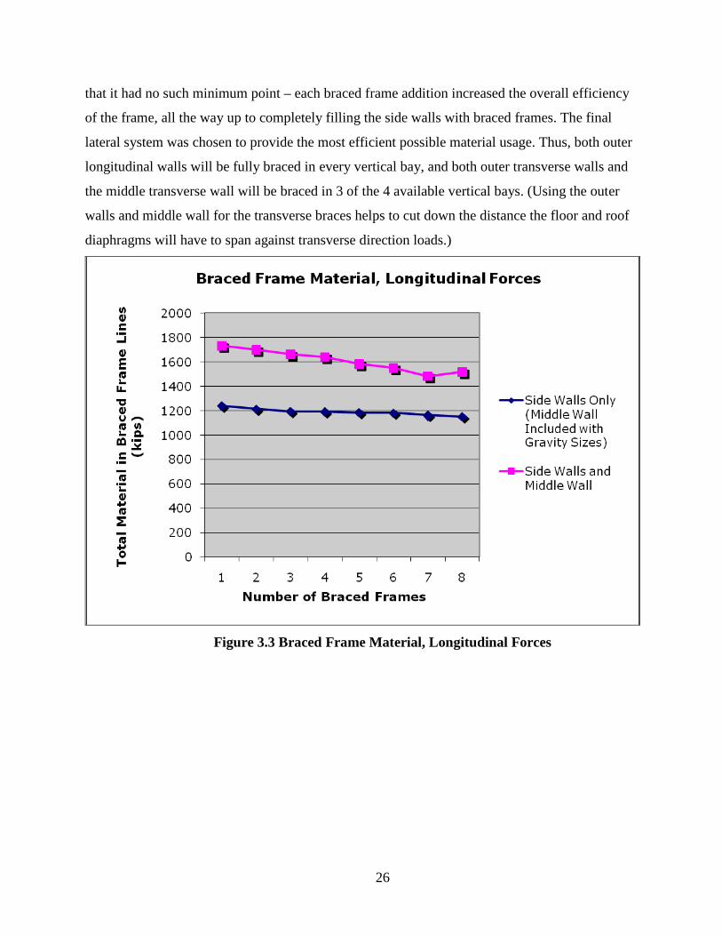
However, there was usually a point at which adding extra braced frames didn’t allow for
an appreciable reduction in braced frame member size, and the total frame material takeoff
would start to increase despite the slightly smaller braced frame member sizes. This is due to the
slenderness factor becoming a governing factor when the braced frame member sizes are reduced
to a certain point. Going above the acceptable slenderness factor in a member forces you to
increase the member size regardless of the load put into the member. Adding braced frame bays
to reduce the load going into each bay no longer allows you to reduce member size once the
slenderness factors for the members are reached. The point at which the material takeoff begins
to suffer is represented by minimums in Figures 3.3 and 3.4, which show the amount of steel
used in the braced frames for each considered case. The points where the lines in the figures start
to move upward after having initially moved downward represent the most efficient braced
frame configuration for that building frame, in terms of total steel weight. The situation in which
the longitudinal wind forces are applied to only the two side walls of the building was unique in
26
that it had no such minimum point – each braced frame addition increased the overall efficiency
of the frame, all the way up to completely filling the side walls with braced frames. The final
lateral system was chosen to provide the most efficient possible material usage. Thus, both outer
longitudinal walls will be fully braced in every vertical bay, and both outer transverse walls and
the middle transverse wall will be braced in 3 of the 4 available vertical bays. (Using the outer
walls and middle wall for the transverse braces helps to cut down the distance the floor and roof
diaphragms will have to span against transverse direction loads.)
Figure 3.3 Braced Frame Material, Longitudinal Forces

27
Figure 3.4 Braced Frame Material, Transverse Forces
Cost Analysis The estimated amount of steel needed for the above system is 3,285,270 pounds. This includes
only the steel joists, braces, beams and columns. If the building were designed with no lateral
system – that is, if it were only composed of gravity-sized members (and had no braces at all),
the amount of steel needed would be 2,498,288 pounds. In this case, the lateral system adds
about 30 percent to the steel material cost. (Whether or not to include a lateral force resisting
system at all is not an option, however, as any building without one will be unstable when lateral
loads are applied.) The difference in labor cost was not calculated, but the relative simplicity of
braced frame connections, in comparison to moment frame connections, adds to the assumption
that the system chosen truly is the most efficient for this building. Connection cost, both in terms
of labor and material, could change the most efficient number of braced frames, as each
additional braced frame connection requires an extra amount of labor and material that isn’t used
for connection that merely transfer gravity loads. Further study of these costs would be required
to determine a truly cost-efficient frame system.

28
CHAPTER 4 - CONCLUSIONS
This report provides an investigation into the details concerning the structural design of a
hospital based upon a universal grid size determined by architects at Cannon Design. The
benefits and drawbacks of moment frames, X-braced frames and chevron braced frames were
compared as lateral force resisting elements for frames utilizing the universal grid. Upon
applying these benefits and drawbacks to a theoretical hospital building model based upon the
Cannon Design universal grid, the possible systems were narrowed down to one – the chevron
braced frame.
The chevron braced frames were used to model full building frames for the theoretical
hospital model, varying the number of braced bays in each frame wall. Designing these different
braced frame configurations allowed me to find the most efficient arrangement of braces for
wind loads applied in both the longitudinal and the transverse directions. Using steel material
takeoffs as the measure of system efficiency, the most economical chevron braced frame
arrangement was determined, given the gravity loads, wind loads and building size determined in
Chapter 3. This arrangement was to fully brace the outer longitudinal walls of my theoretical
building, and to brace 3 out the 4 vertical bays of the outer transverse walls as well as the middle
transverse wall. Figure 4.1 illustrates this braced frame arrangement. Fully bracing the exterior
walls is not absolutely necessary for the design to work, however, and in a real building, the
number of braced frames would likely need to be reduced in order to meet architectural
requirements, like desired available wall opening space. The optimum bracing determined by this
analysis only takes structural material takeoff into account, and adding additional braced frame
bays usually allowed for enough member size reduction to be worthwhile from a pure material
takeoff standpoint.

29
Figure 4.1 Final Braced Frame Arrangement
The main lesson to be learned from this project is that simplifying a building design
process by starting with a pre-defined universal grid does not eliminate the need to make many
important choices. The universal grid does not provide a one-size-fits-all structural system –
lateral system choices need to be narrowed down by considering a series of other factors, which
may or may not hold for buildings in different areas or of different sizes, regardless of whether
they use the universal grid. The report’s building’s location in Chicago, IL determined the
governing lateral loads, and a similarly sized building in a different location would have to resist
different loads, which could drastically alter the braced frame arrangement shown in Figure 4.1.
Also, a different sized hospital using the universal grid system would have a very different
behavior under lateral loads, possibly different enough that a basic lateral element other than the
chevron braced frame would be ideal. However, basic trends and patterns in performance
between different lateral systems and configurations were identified in this report, and this
information could save engineering time by providing useful starting points when designing a
building with the universal grid.
30
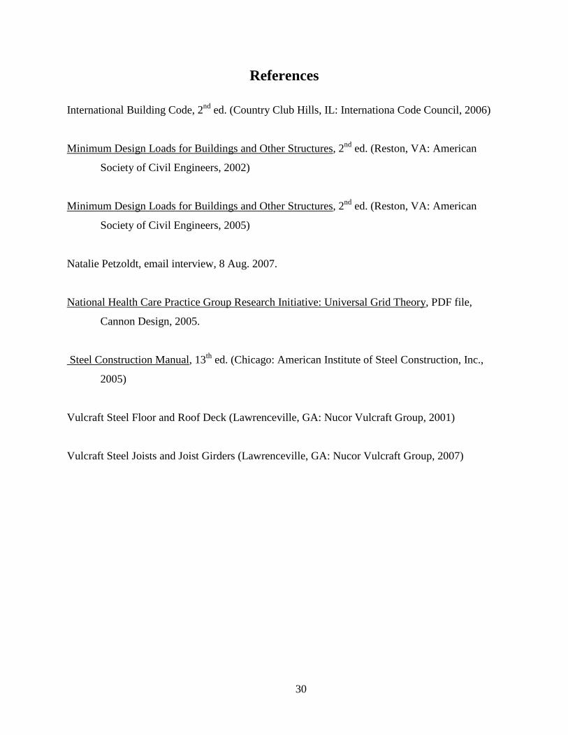
References
International Building Code, 2nd ed. (Country Club Hills, IL: Internationa Code Council, 2006)
Minimum Design Loads for Buildings and Other Structures
, 2nd ed. (Reston, VA: American
Society of Civil Engineers, 2002)
Minimum Design Loads for Buildings and Other Structures
, 2nd ed. (Reston, VA: American
Society of Civil Engineers, 2005)
Natalie Petzoldt, email interview, 8 Aug. 2007.
National Health Care Practice Group Research Initiative: Universal Grid Theory
, PDF file,
Cannon Design, 2005.
Steel Construction Manual
, 13th ed. (Chicago: American Institute of Steel Construction, Inc.,
2005)
Vulcraft Steel Floor and Roof Deck (Lawrenceville, GA: Nucor Vulcraft Group, 2001)
Vulcraft Steel Joists and Joist Girders (Lawrenceville, GA: Nucor Vulcraft Group, 2007)
31
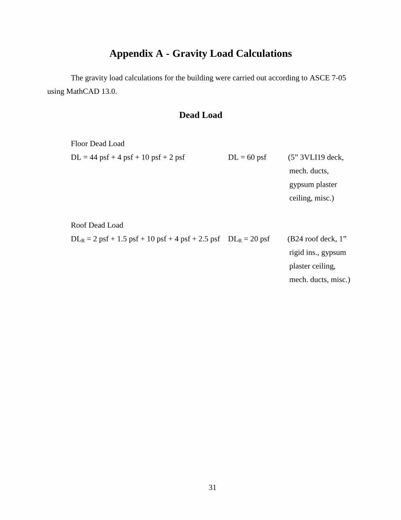
Appendix A - Gravity Load Calculations
The gravity load calculations for the building were carried out according to ASCE 7-05
using MathCAD 13.0.
Dead Load
Floor Dead Load
DL = 44 psf + 4 psf + 10 psf + 2 psf DL = 60 psf (5” 3VLI19 deck,
mech. ducts,
gypsum plaster
ceiling, misc.)
Roof Dead Load
DLR = 2 psf + 1.5 psf + 10 psf + 4 psf + 2.5 psf DLR = 20 psf (B24 roof deck, 1”
rigid ins., gypsum
plaster ceiling,
mech. ducts, misc.)
32
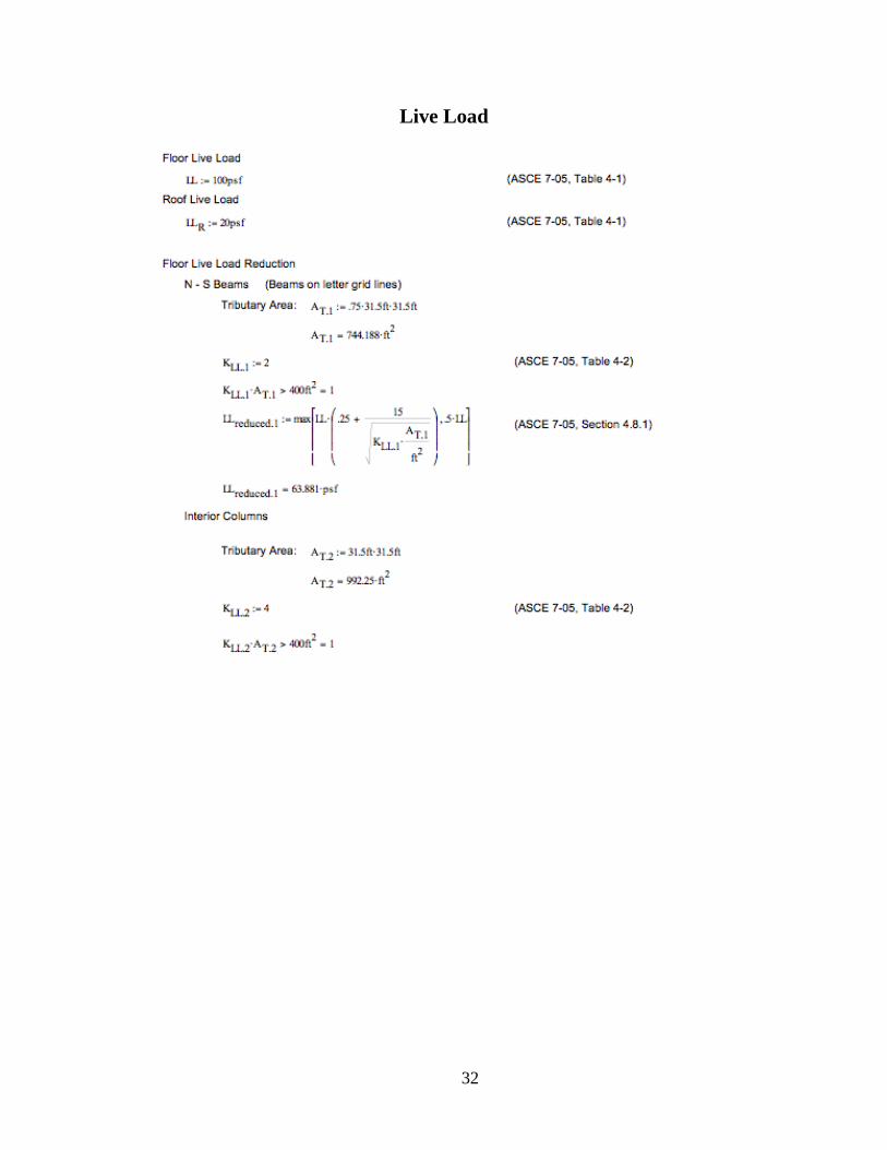
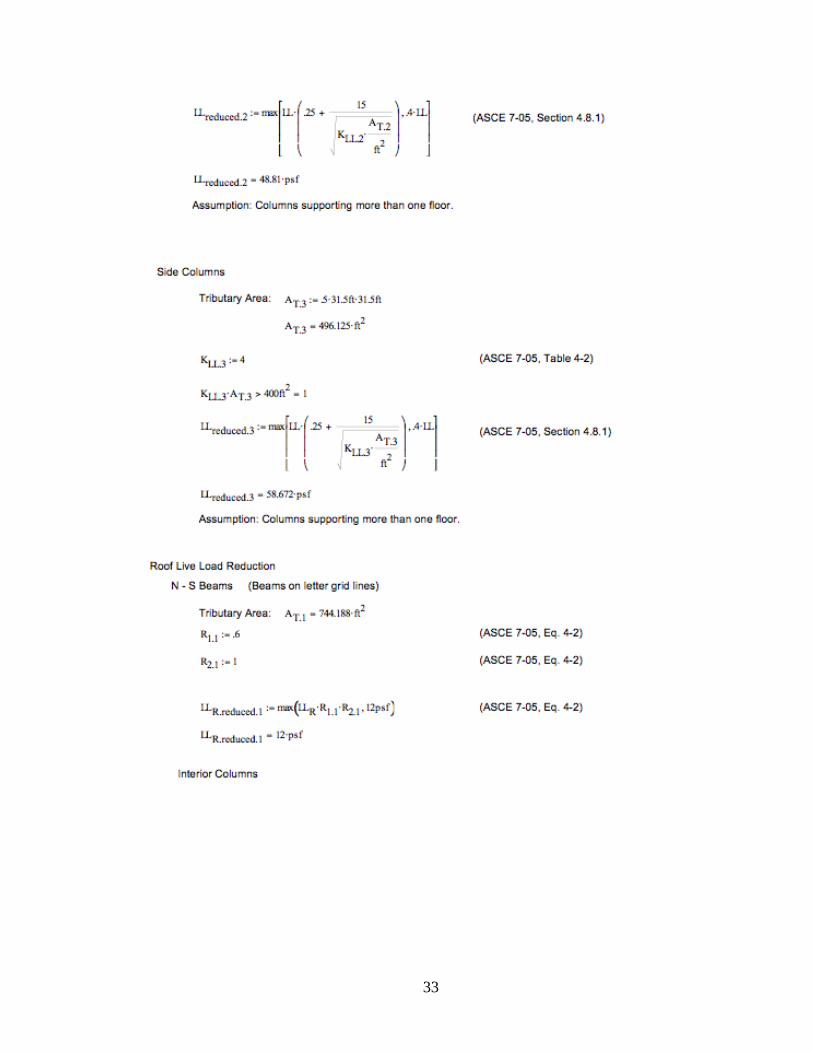
Live Load
33

34
Snow Load

35
Appendix B - Gravity Member Sizing Calculations
The gravity member sizing calculations for the building were carried out using Microsoft
Excel.

36
Steel Joist Design Design Per Vulcraft Steel Joists and Joist Girders 2003 Manual Constant Uniform Loading, Simply Supported
Name: Grant Buell Project: Master's Research
Member: RJ1
User entered Important result
INPUT
Geometric Properties Span (ft) 31.5 See floor plan
Trib. width (ft) 5.25 See floor plan Superimposed Loading
Dead load (psf) 20 See load calculations Live/snow load (psf) 24 See load calculations
Joist Properties
Designation 18K5 See Vulcraft Steel Joist and Joist Girders Manual
Maximum wtotal (plf) 242 See Vulcraft Steel Joist and Joist Girders Manual
Maximum wlive (for ΔLL < L/360) (plf) 132 See Vulcraft Steel Joist and Joist Girders Manual
OUTPUT
Total Service Load wtotal (plf) 231 wlive (plf) 126
End reactionstotal (k) 3.63825 End reactionsdead (k) 1.65375
End reactionslive/snow (k) 1.9845 Design Checks
Okay for total load? OK Okay for live load? (ΔLL < L/360) OK Okay for live load? (ΔLL < L/240) OK

37
Steel Beam Design Design Per AISC Steel Construction Manual, 13th Edition Constant Uniform Loading with Either 5 or 0 Equally Spaced Equal Point Loads
Name: Grant Buell Project: Master's Research
Member: RB1 User entered Important result
INPUT OUTPUT Geometric Properties Loading
L (ft) 31.5 See plan Dead Live/Snow Ultimate Trib. width (ft) 0 See plan w (klf) 0 0 0
Supporting back-to-back joists? (Yes/No) Yes M (kip-ft) 78.1396875 93.767625 243.795825
Superimposed Loading V (kips) 8.26875 9.9225 25.7985
N 5 N = no. of point loads Deflection
Dead Live/Snow Max ΔL (in) 1.575 P (kips) 3.3075 3.969 See load calcs Required Ix (LL) (in4) 358.5157
Surface load (ksf) 0 0 See load calcs ΔL (in) 1.1072 Line load (klf) 0 0 See load calcs Bending Check
LRFD Load Factor 1.2 1.6 IBC 1605.2.1 Okay for bending? OK Steel Beam Properties Shear Check
E (ksi) 29000 Okay for shear? OK Size W18X35 AISC Table 1-1 Deflection Check bf (in) 6.00 AISC Table 1-1 Okay for ΔL? OK
ΦbMnx (k-ft) 249 AISC Table 3-2 Other
ΦvVnx (k) 159 AISC Table 3-2 Adequate width for joist bearing? OK
Ix (in4) 510 AISC Table 1-1 Limit ΔL to L/___ 240 IBC Table 1604.3 Limit ΔL to _" for
veneer N/A
38
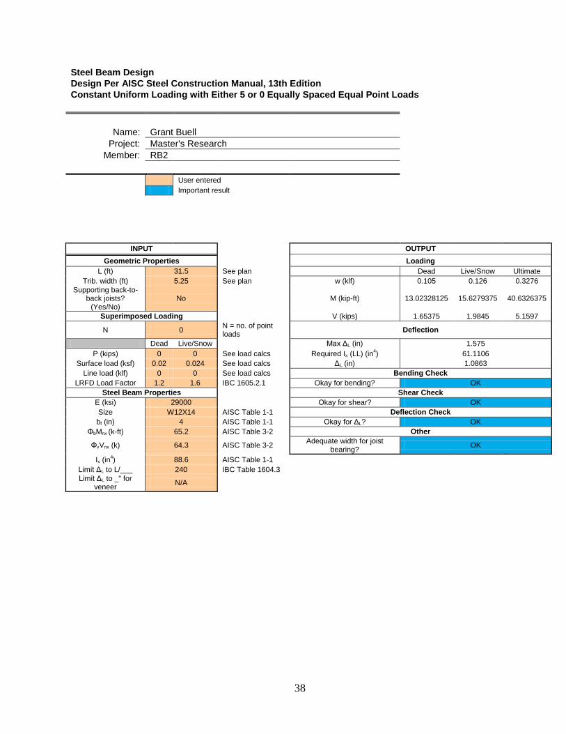
Steel Beam Design Design Per AISC Steel Construction Manual, 13th Edition Constant Uniform Loading with Either 5 or 0 Equally Spaced Equal Point Loads
Name: Grant Buell Project: Master's Research
Member: RB2 User entered Important result
INPUT OUTPUT Geometric Properties Loading
L (ft) 31.5 See plan Dead Live/Snow Ultimate Trib. width (ft) 5.25 See plan w (klf) 0.105 0.126 0.3276
Supporting back-to-back joists?
(Yes/No) No M (kip-ft) 13.02328125 15.6279375 40.6326375
Superimposed Loading V (kips) 1.65375 1.9845 5.1597
N 0 N = no. of point loads Deflection
Dead Live/Snow Max ΔL (in) 1.575 P (kips) 0 0 See load calcs Required Ix (LL) (in4) 61.1106
Surface load (ksf) 0.02 0.024 See load calcs ΔL (in) 1.0863 Line load (klf) 0 0 See load calcs Bending Check
LRFD Load Factor 1.2 1.6 IBC 1605.2.1 Okay for bending? OK Steel Beam Properties Shear Check
E (ksi) 29000 Okay for shear? OK Size W12X14 AISC Table 1-1 Deflection Check bf (in) 4 AISC Table 1-1 Okay for ΔL? OK
ΦbMnx (k-ft) 65.2 AISC Table 3-2 Other
ΦvVnx (k) 64.3 AISC Table 3-2 Adequate width for joist bearing? OK
Ix (in4) 88.6 AISC Table 1-1 Limit ΔL to L/___ 240 IBC Table 1604.3 Limit ΔL to _" for
veneer N/A

39
Steel Beam Design Design Per AISC Steel Construction Manual, 13th Edition Constant Uniform Loading with Either 5 or 0 Equally Spaced Equal Point Loads
Name: Grant Buell Project: Master's Research
Member: RB3 User entered Important result
INPUT OUTPUT Geometric Properties Loading
L (ft) 31.5 See plan Dead Live/Snow Ultimate Trib. width (ft) 0 See plan w (klf) 0 0 0
Supporting back-to-back joists?
(Yes/No) No M (kip-ft) 39.06984375 46.8838125 121.8979125
Superimposed Loading V (kips) 4.134375 4.96125 12.89925
N 5 N = no. of point loads Deflection
Dead Live/Snow Max ΔL (in) 1.575 P (kips) 1.65375 1.9845 See load calcs Required Ix (LL) (in4) 179.2578
Surface load (ksf) 0 0 See load calcs ΔL (in) 1.4187
Line load (klf) 0 0 See load calcs Bending Check LRFD Load
Factor 1.2 1.6 IBC 1605.2.1 Okay for bending? OK
Steel Beam Properties Shear Check E (ksi) 29000 Okay for shear? OK Size W8X28 AISC Table 1-1 Deflection Check bf (in) 5 AISC Table 1-1 Okay for ΔL? OK
ΦbMnx (k-ft) 125 AISC Table 3-2 Other
ΦvVnx (k) 94.8 AISC Table 3-2 Adequate width for joist bearing? OK
Ix (in4) 199 AISC Table 1-1 Limit ΔL to L/___ 240 IBC Table 1604.3 Limit ΔL to _" for
veneer N/A

40
Steel Beam Design Design Per AISC Steel Construction Manual, 13th Edition Constant Uniform Loading with Either 5 or 0 Equally Spaced Equal Point Loads
Name: Grant Buell Project: Master's Research
Member: RB4 User entered Important result
INPUT OUTPUT Geometric Properties Loading
L (ft) 31.5 See plan Dead Live/Snow Ultimate Trib. width (ft) 2.625 See plan w (klf) 0.0525 0.063 0.1638
Supporting back-to-back joists?
(Yes/No) No M (kip-ft) 6.511640625 7.81396875 20.31631875
Superimposed Loading V (kips) 0.826875 0.99225 2.57985
N 0 N = no. of point loads Deflection
Dead Live/Snow Max ΔL (in) 1.575 P (kips) 0 0 See load calcs Required Ix (LL) (in4) 30.5553
Surface load (ksf) 0.02 0.024 See load calcs ΔL (in) 0.8945 Line load (klf) 0 0 See load calcs Bending Check
LRFD Load Factor 1.2 1.6 IBC 1605.2.1 Okay for bending? OK Steel Beam Properties Shear Check
E (ksi) 29000 Okay for shear? OK Size W10X12 AISC Table 1-1 Deflection Check bf (in) 4 AISC Table 1-1 Okay for ΔL? OK
ΦbMnx (k-ft) 46.9 AISC Table 3-2 Other
ΦvVnx (k) 56.3 AISC Table 3-2 Adequate width for joist bearing? OK
Ix (in4) 53.8 AISC Table 1-1 Limit ΔL to L/___ 240 IBC Table 1604.3 Limit ΔL to _" for
veneer N/A

41
Steel Joist Design Design Per Vulcraft Steel Joists and Joist Girders 2003 Manual Constant Uniform Loading, Simply Supported
Name: Grant Buell Project: Master's Research
Member: FJ1
User entered Important result
INPUT
Geometric Properties Span (ft) 31.5 See floor plan
Trib. width (ft) 2.625 See floor plan Superimposed Loading
Dead load (psf) 60 See load calculations Live/snow load (psf) 100 See load calculations
Joist Properties
Designation 20K10 See Vulcraft Steel Joist and Joist Girders Manual
Maximum wtotal (plf) 468 See Vulcraft Steel Joist and Joist Girders Manual
Maximum wlive (for ΔLL < L/360) (plf) 276 See Vulcraft Steel Joist and Joist Girders Manual
OUTPUT
Total Service Load wtotal (plf) 420 wlive (plf) 262.5
End reactionstotal (k) 6.615 End reactionsdead (k) 2.480625
End reactionslive/snow (k) 4.134375 Design Checks
Okay for total load? OK Okay for live load? (ΔLL < L/360) OK Okay for live load? (ΔLL < L/240) OK

42
Steel Beam Design Design Per AISC Steel Construction Manual, 13th Edition Constant Uniform Loading with Either 5 or 0 Equally Spaced Equal Point Loads
Name: Grant Buell Project: Master's Research
Member: FB1 User entered Important result
INPUT OUTPUT Geometric Properties Loading
L (ft) 31.5 See plan Dead Live/Snow Ultimate Trib. width (ft) 0 See plan w (klf) 0 0 0
Supporting back-to-back
joists? (Yes/No) Yes M (kip-ft) 117.2095313 195.3492188 453.2101875
Superimposed Loading V (kips) 12.403125 20.671875 47.95875
N 5 N = no. of point loads Deflection
Dead Live/Snow Max ΔL (in) 1.575 P (kips) 4.96125 8.26875 See load calcs Required Ix (LL) (in4) 746.9076
Surface load (ksf) 0 0 See load calcs ΔL (in) 1.0319
Line load (klf) 0 0 See load calcs Bending Check LRFD Load
Factor 1.2 1.6 IBC 1605.2.1 Okay for bending? OK
Steel Beam Properties Shear Check E (ksi) 29000 Okay for shear? OK Size W21X55 AISC Table 1-1 Deflection Check bf (in) 8.22 AISC Table 1-1 Okay for ΔL? OK
ΦbMnx (k-ft) 473 AISC Table 3-2 Other
ΦvVnx (k) 234 AISC Table 3-2 Adequate width for joist bearing? OK
Ix (in4) 1140 AISC Table 1-1 Limit ΔL to
L/___ 240 IBC Table 1604.3
Limit ΔL to _" for veneer N/A

43
Steel Beam Design Design Per AISC Steel Construction Manual, 13th Edition Constant Uniform Loading with Either 5 or 0 Equally Spaced Equal Point Loads
Name: Grant Buell Project: Master's Research
Member: FB2 User entered Important result
INPUT OUTPUT Geometric Properties Loading
L (ft) 31.5 See plan Dead Live/Snow Ultimate Trib. width (ft) 2.625 See plan w (klf) 0.1575 0.2625 0.609
Supporting back-to-back joists?
(Yes/No) No M (kip-ft) 19.53492188 32.55820313 75.53503125
Superimposed Loading V (kips) 2.480625 4.134375 9.59175
N 0 N = no. of point loads Deflection
Dead Live/Snow Max ΔL (in) 1.575 P (kips) 0 0 See load calcs Required Ix (LL) (in4) 127.3138
Surface load (ksf) 0.06 0.1 See load calcs ΔL (in) 1.5425 Line load (klf) 0 0 See load calcs Bending Check
LRFD Load Factor 1.2 1.6 IBC 1605.2.1 Okay for bending? OK Steel Beam Properties Shear Check
E (ksi) 29000 Okay for shear? OK Size W12X19 AISC Table 1-1 Deflection Check bf (in) 4.01 AISC Table 1-1 Okay for ΔL? OK
ΦbMnx (k-ft) 92.6 AISC Table 3-2 Other
ΦvVnx (k) 85.7 AISC Table 3-2 Adequate width for joist bearing? OK
Ix (in4) 130 AISC Table 1-1 Limit ΔL to L/___ 240 IBC Table 1604.3 Limit ΔL to _" for
veneer N/A

44
Steel Beam Design Design Per AISC Steel Construction Manual, 13th Edition Constant Uniform Loading with Either 5 or 0 Equally Spaced Equal Point Loads
Name: Grant Buell Project: Master's Research
Member: FB3 User entered Important result
INPUT OUTPUT Geometric Properties Loading
L (ft) 31.5 See plan Dead Live/Snow Ultimate Trib. width (ft) 0 See plan w (klf) 0.18 0 0.216
Supporting back-to-back
joists? (Yes/No) No M (kip-ft) 80.93039063 97.67460938 253.3958438
Superimposed Loading V (kips) 9.0365625 10.3359375 27.381375
N 5 N = no. of point loads Deflection
Dead Live/Snow Max ΔL (in) 1.575 P (kips) 2.480625 4.134375 See load calcs Required Ix (LL) (in4) 373.4538
Surface load (ksf) 0 0 See load calcs ΔL (in) 0.9611
Line load (klf) 0.18 0 See load calcs Bending Check LRFD Load
Factor 1.2 1.6 IBC 1605.2.1 Okay for bending? OK
Steel Beam Properties Shear Check E (ksi) 29000 Okay for shear? OK Size W18X40 AISC Table 1-1 Deflection Check bf (in) 6.02 AISC Table 1-1 Okay for ΔL? OK
ΦbMnx (k-ft) 294 AISC Table 3-2 Other
ΦvVnx (k) 169 AISC Table 3-2 Adequate width for joist bearing? OK
Ix (in4) 612 AISC Table 1-1 Limit ΔL to
L/___ 240 IBC Table 1604.3
Limit ΔL to _" for veneer N/A
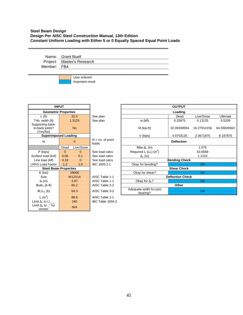
45
Steel Beam Design Design Per AISC Steel Construction Manual, 13th Edition Constant Uniform Loading with Either 5 or 0 Equally Spaced Equal Point Loads
Name: Grant Buell Project: Master's Research
Member: FB4 User entered Important result
INPUT OUTPUT Geometric Properties Loading
L (ft) 31.5 See plan Dead Live/Snow Ultimate Trib. width (ft) 1.3125 See plan w (klf) 0.25875 0.13125 0.5205
Supporting back-to-back joists?
(Yes/No) No M (kip-ft) 32.09308594 16.27910156 64.55826563
Superimposed Loading V (kips) 4.0753125 2.0671875 8.197875
N 0 N = no. of point loads Deflection
Dead Live/Snow Max ΔL (in) 1.575 P (kips) 0 0 See load calcs Required Ix (LL) (in4) 63.6569
Surface load (ksf) 0.06 0.1 See load calcs ΔL (in) 1.1316 Line load (klf) 0.18 0 See load calcs Bending Check
LRFD Load Factor 1.2 1.6 IBC 1605.2.1 Okay for bending? OK Steel Beam Properties Shear Check
E (ksi) 29000 Okay for shear? OK Size W12X14 AISC Table 1-1 Deflection Check bf (in) 3.97 AISC Table 1-1 Okay for ΔL? OK
ΦbMnx (k-ft) 65.2 AISC Table 3-2 Other
ΦvVnx (k) 64.3 AISC Table 3-2 Adequate width for joist bearing? OK
Ix (in4) 88.6 AISC Table 1-1 Limit ΔL to L/___ 240 IBC Table 1604.3 Limit ΔL to _" for
veneer N/A

46
Steel Column Design Design Per AISC Steel Construction Manual, 13th Edition Gravity Only
Name: Grant Buell Project: Master's Research
Member: C1-1
User entered Important result
INPUT Column Properties
Size W8X31 K 0.5
L (ft) 36 ΦcPn (kip) 178 AISC Manual Table 4-1
Beam Reactions onto Column See beam/joist spreadsheets, load calculations
Dead Live 4.134375 4.96125 RB3 0.826875 0.99225 RB4 6.2015625 10.3359375 FB3 4.0753125 2.0671875 FB4
Load Factors Dead Live 1.2 1.6
OUTPUT
Loads Total Dead Total Live
15.238125 18.356625 Effective Length
KL (ft) 18 Compression Check
Factored Load Pu (k) 47.65635 ΦcPn > Pu? OK

47
Steel Column Design Design Per AISC Steel Construction Manual, 13th Edition Gravity Only
Name: Grant Buell Project: Master's Research
Member: C1-2
User entered Important result
INPUT Column Properties
Size W8X31 K 0.5
L (ft) 36 ΦcPn (kip) 178 AISC Manual Table 4-1
Beam Reactions onto Column See beam/joist spreadsheets, load calculations
Dead Live 6.2015625 10.3359375 FB3 4.0753125 2.0671875 FB4 6.2015625 10.3359375 FB3 4.0753125 2.0671875 FB4 15.238125 18.356625 C1-1
Load Factors Dead Live 1.2 1.6
OUTPUT
Loads Total Dead Total Live
35.791875 43.162875 Effective Length
KL (ft) 18 Compression Check
Factored Load Pu (k) 112.01085 ΦcPn > Pu? OK

48
Steel Column Design Design Per AISC Steel Construction Manual, 13th Edition Gravity Only
Name: Grant Buell Project: Master's Research
Member: C1-3
User entered Important result
INPUT Column Properties
Size W8X31 K 0.5
L (ft) 36 ΦcPn (kip) 178 AISC Manual Table 4-1
Beam Reactions onto Column See beam/joist spreadsheets, load calculations
Dead Live 6.2015625 10.3359375 FB3 4.0753125 2.0671875 FB4 6.2015625 10.3359375 FB3 4.0753125 2.0671875 FB4 35.791875 43.162875 C1-2
Load Factors Dead Live 1.2 1.6
OUTPUT
Loads Total Dead Total Live
56.345625 67.969125 Effective Length
KL (ft) 18 Compression Check
Factored Load Pu (k) 176.36535 ΦcPn > Pu? OK

49
Steel Column Design Design Per AISC Steel Construction Manual, 13th Edition Gravity Only
Name: Grant Buell Project: Master's Research
Member: C1-4
User entered Important result
INPUT Column Properties
Size W10X45 K 0.5
L (ft) 36 ΦcPn (kip) 256 AISC Manual Table 4-1
Beam Reactions onto Column See beam/joist spreadsheets, load calculations
Dead Live 6.2015625 10.3359375 FB3 4.0753125 2.0671875 FB4 6.2015625 10.3359375 FB3 4.0753125 2.0671875 FB4 56.345625 67.969125 C1-3
Load Factors Dead Live 1.2 1.6
OUTPUT
Loads Total Dead Total Live
76.899375 92.775375 Effective Length
KL (ft) 18 Compression Check
Factored Load Pu (k) 240.71985 ΦcPn > Pu? OK

50
Steel Column Design Design Per AISC Steel Construction Manual, 13th Edition Gravity Only
Name: Grant Buell Project: Master's Research
Member: C1-5
User entered Important result
INPUT Column Properties
Size W10X49 K 0.5
L (ft) 36 ΦcPn (kip) 383 AISC Manual Table 4-1
Beam Reactions onto Column See beam/joist spreadsheets, load calculations
Dead Live 6.2015625 10.3359375 FB3 4.0753125 2.0671875 FB4 6.2015625 10.3359375 FB3 4.0753125 2.0671875 FB4 76.899375 92.775375 C1-4
Load Factors Dead Live 1.2 1.6
OUTPUT
Loads Total Dead Total Live
97.453125 117.581625 Effective Length
KL (ft) 18 Compression Check
Factored Load Pu (k) 305.07435 ΦcPn > Pu? OK

51
Steel Column Design Design Per AISC Steel Construction Manual, 13th Edition Gravity Only
Name: Grant Buell Project: Master's Research
Member: C2-1
User entered Important result
INPUT Column Properties
Size W8X31 K 0.5
L (ft) 36 ΦcPn (kip) 178 AISC Manual Table 4-1
Beam Reactions onto Column See beam/joist spreadsheets, load calculations
Dead Live 1.65375 1.9845 RB2 4.134375 4.96125 RB3 4.134375 4.96125 RB3 2.480625 4.134375 FB2 9.0365625 10.3359375 FB3 9.0365625 10.3359375 FB3
Load Factors Dead Live 1.2 1.6
OUTPUT
Loads Total Dead Total Live
30.47625 36.71325 Effective Length
KL (ft) 18 Compression Check
Factored Load Pu (k) 95.3127 ΦcPn > Pu? OK

52
Steel Column Design Design Per AISC Steel Construction Manual, 13th Edition Gravity Only
Name: Grant Buell Project: Master's Research
Member: C2-2
User entered Important result
INPUT Column Properties
Size W10X39 K 0.5
L (ft) 36 ΦcPn (kip) 216 AISC Manual Table 4-1
Beam Reactions onto Column See beam/joist spreadsheets, load calculations
Dead Live 2.480625 4.134375 FB2 6.2015625 10.3359375 FB3 6.2015625 10.3359375 FB3 2.480625 4.134375 FB2 9.0365625 10.3359375 FB3 9.0365625 10.3359375 FB3 24.80625 36.71325 C2-1
Load Factors Dead Live 1.2 1.6
OUTPUT
Loads Total Dead Total Live
60.24375 86.32575 Effective Length
KL (ft) 18 Compression Check
Factored Load Pu (k) 210.4137 ΦcPn > Pu? OK

53
Steel Column Design Design Per AISC Steel Construction Manual, 13th Edition Gravity Only
Name: Grant Buell Project: Master's Research
Member: C2-3
User entered Important result
INPUT Column Properties
Size W10X49 K 0.5
L (ft) 36 ΦcPn (kip) 383 AISC Manual Table 4-1
Beam Reactions onto Column See beam/joist spreadsheets, load calculations
Dead Live 2.480625 4.134375 FB2 6.2015625 10.3359375 FB3 6.2015625 10.3359375 FB3 2.480625 4.134375 FB2 9.0365625 10.3359375 FB3 9.0365625 10.3359375 FB3 54.57375 86.32575 C2-2
Load Factors Dead Live 1.2 1.6
OUTPUT
Loads Total Dead Total Live
90.01125 135.93825 Effective Length
KL (ft) 18 Compression Check
Factored Load Pu (k) 325.5147 ΦcPn > Pu? OK

54
Steel Column Design Design Per AISC Steel Construction Manual, 13th Edition Gravity Only
Name: Grant Buell Project: Master's Research
Member: C2-4
User entered Important result
INPUT Column Properties
Size W12X58 K 0.5
L (ft) 36 ΦcPn (kip) 446 AISC Manual Table 4-1
Beam Reactions onto Column See beam/joist spreadsheets, load calculations
Dead Live 2.480625 4.134375 FB2 6.2015625 10.3359375 FB3 6.2015625 10.3359375 FB3 2.480625 4.134375 FB2 9.0365625 10.3359375 FB3 9.0365625 10.3359375 FB3 84.34125 135.93825 C2-3
Load Factors Dead Live 1.2 1.6
OUTPUT
Loads Total Dead Total Live
119.77875 185.55075 Effective Length
KL (ft) 18 Compression Check
Factored Load Pu (k) 440.6157 ΦcPn > Pu? OK

55
Steel Column Design Design Per AISC Steel Construction Manual, 13th Edition Gravity Only
Name: Grant Buell Project: Master's Research
Member: C2-5
User entered Important result
INPUT Column Properties
Size W12X65 K 0.5
L (ft) 36 ΦcPn (kip) 591 AISC Manual Table 4-1
Beam Reactions onto Column See beam/joist spreadsheets, load calculations
Dead Live 2.480625 4.134375 FB2 6.2015625 10.3359375 FB3 6.2015625 10.3359375 FB3 2.480625 4.134375 FB2 9.0365625 10.3359375 FB3 9.0365625 10.3359375 FB3 114.10875 185.55075 C2-4
Load Factors Dead Live 1.2 1.6
OUTPUT
Loads Total Dead Total Live
149.54625 235.16325 Effective Length
KL (ft) 18 Compression Check
Factored Load Pu (k) 555.7167 ΦcPn > Pu? OK
56
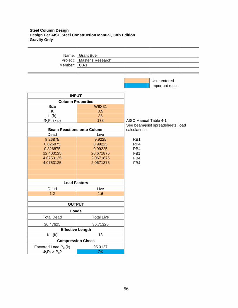
Steel Column Design Design Per AISC Steel Construction Manual, 13th Edition Gravity Only
Name: Grant Buell Project: Master's Research
Member: C3-1
User entered Important result
INPUT Column Properties
Size W8X31 K 0.5
L (ft) 36 ΦcPn (kip) 178 AISC Manual Table 4-1
Beam Reactions onto Column See beam/joist spreadsheets, load calculations
Dead Live 8.26875 9.9225 RB1 0.826875 0.99225 RB4 0.826875 0.99225 RB4 12.403125 20.671875 FB1 4.0753125 2.0671875 FB4 4.0753125 2.0671875 FB4
Load Factors Dead Live 1.2 1.6
OUTPUT
Loads Total Dead Total Live
30.47625 36.71325 Effective Length
KL (ft) 18 Compression Check
Factored Load Pu (k) 95.3127 ΦcPn > Pu? OK

57
Steel Column Design Design Per AISC Steel Construction Manual, 13th Edition Gravity Only
Name: Grant Buell Project: Master's Research
Member: C3-2
User entered Important result
INPUT Column Properties
Size W8X40 K 0.5
L (ft) 36 ΦcPn (kip) 233 AISC Manual Table 4-1
Beam Reactions onto Column See beam/joist spreadsheets, load calculations
Dead Live 12.403125 20.671875 FB1 4.0753125 2.0671875 FB4 4.0753125 2.0671875 FB4 12.403125 20.671875 FB1 4.0753125 2.0671875 FB4 4.0753125 2.0671875 FB4 30.47625 36.71325 C3-1
Load Factors Dead Live 1.2 1.6
OUTPUT
Loads Total Dead Total Live
71.58375 86.32575 Effective Length
KL (ft) 18 Compression Check
Factored Load Pu (k) 224.0217 ΦcPn > Pu? OK

58
Steel Column Design Design Per AISC Steel Construction Manual, 13th Edition Gravity Only
Name: Grant Buell Project: Master's Research
Member: C3-3
User entered Important result
INPUT Column Properties
Size W10X49 K 0.5
L (ft) 36 ΦcPn (kip) 383 AISC Manual Table 4-1
Beam Reactions onto Column See beam/joist spreadsheets, load calculations
Dead Live 12.403125 20.671875 FB1 4.0753125 2.0671875 FB4 4.0753125 2.0671875 FB4 12.403125 20.671875 FB1 4.0753125 2.0671875 FB4 4.0753125 2.0671875 FB4 71.58375 86.32575 C3-2
Load Factors Dead Live 1.2 1.6
OUTPUT
Loads Total Dead Total Live
112.69125 135.93825 Effective Length
KL (ft) 18 Compression Check
Factored Load Pu (k) 352.7307 ΦcPn > Pu? OK

59
Steel Column Design Design Per AISC Steel Construction Manual, 13th Edition Gravity Only
Name: Grant Buell Project: Master's Research
Member: C3-4
User entered Important result
INPUT Column Properties
Size W12X65 K 0.5
L (ft) 36 ΦcPn (kip) 591 AISC Manual Table 4-1
Beam Reactions onto Column See beam/joist spreadsheets, load calculations
Dead Live 12.403125 20.671875 FB1 4.0753125 2.0671875 FB4 4.0753125 2.0671875 FB4 12.403125 20.671875 FB1 4.0753125 2.0671875 FB4 4.0753125 2.0671875 FB4 112.69125 135.93825 C3-3
Load Factors Dead Live 1.2 1.6
OUTPUT
Loads Total Dead Total Live
153.79875 185.55075 Effective Length
KL (ft) 18 Compression Check
Factored Load Pu (k) 481.4397 ΦcPn > Pu? OK
60
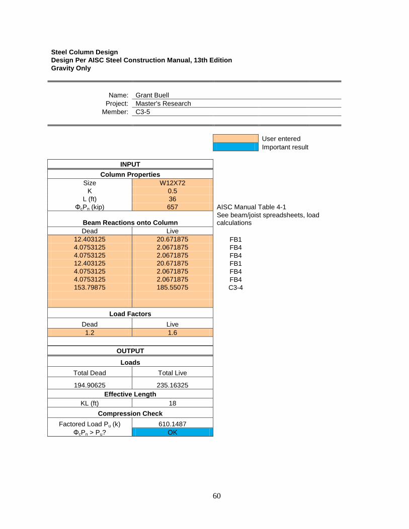
Steel Column Design Design Per AISC Steel Construction Manual, 13th Edition Gravity Only
Name: Grant Buell Project: Master's Research
Member: C3-5
User entered Important result
INPUT Column Properties
Size W12X72 K 0.5
L (ft) 36 ΦcPn (kip) 657 AISC Manual Table 4-1
Beam Reactions onto Column See beam/joist spreadsheets, load calculations
Dead Live 12.403125 20.671875 FB1 4.0753125 2.0671875 FB4 4.0753125 2.0671875 FB4 12.403125 20.671875 FB1 4.0753125 2.0671875 FB4 4.0753125 2.0671875 FB4 153.79875 185.55075 C3-4
Load Factors Dead Live 1.2 1.6
OUTPUT
Loads Total Dead Total Live
194.90625 235.16325 Effective Length
KL (ft) 18 Compression Check
Factored Load Pu (k) 610.1487 ΦcPn > Pu? OK

61
Steel Column Design Design Per AISC Steel Construction Manual, 13th Edition Gravity Only
Name: Grant Buell Project: Master's Research
Member: C4-1
User entered Important result
INPUT Column Properties
Size W8X31 K 0.5
L (ft) 36 ΦcPn (kip) 178 AISC Manual Table 4-1
Beam Reactions onto Column See beam/joist spreadsheets, load calculations
Dead Live 8.26875 9.9225 RB1 8.26875 9.9225 RB1 1.65375 1.9845 RB2 1.65375 1.9845 FB2
12.403125 20.671875 FB1 12.403125 20.671875 FB1 2.480625 4.134375 FB2 2.480625 4.134375 FB2
Load Factors
Dead Live 1.2 1.6
OUTPUT
Loads Total Dead Total Live
49.6125 73.4265 Effective Length
KL (ft) 18 Compression Check
Factored Load Pu (k) 177.0174 ΦcPn > Pu? OK
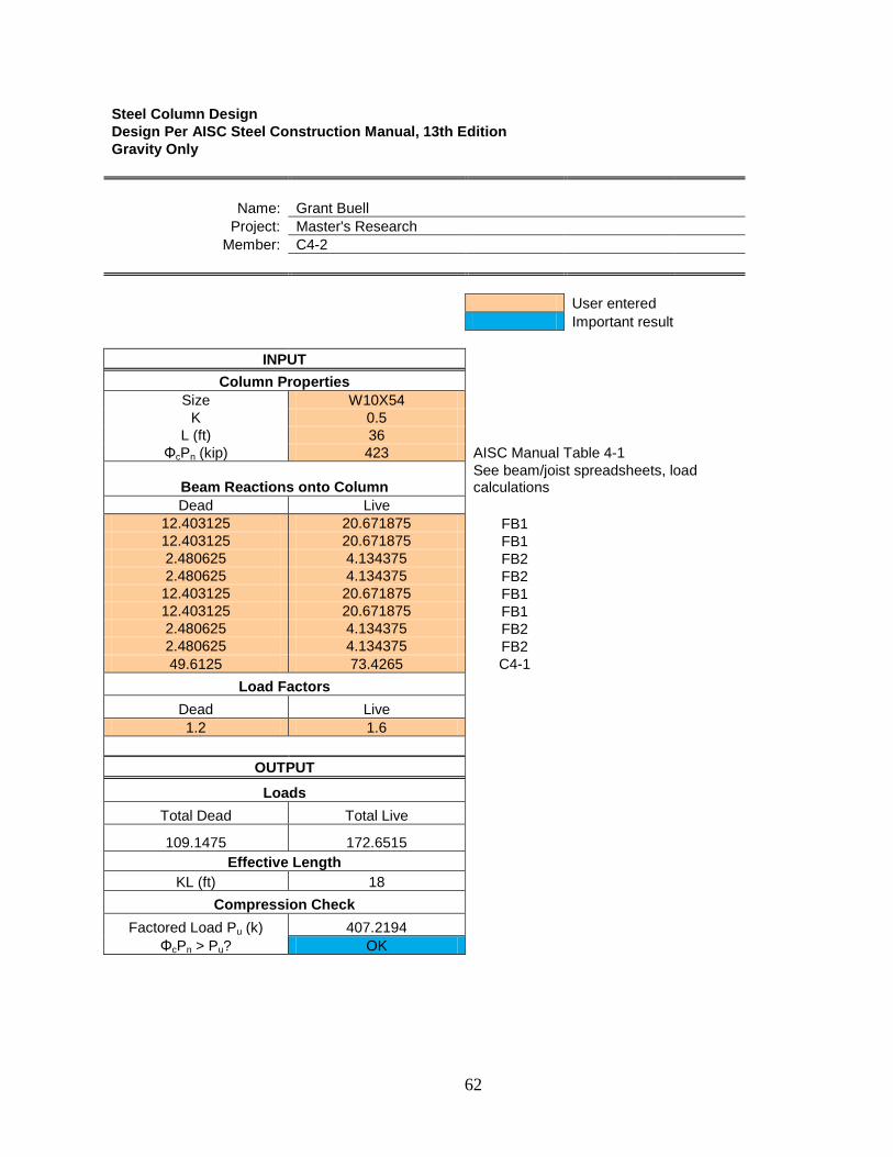
62
Steel Column Design Design Per AISC Steel Construction Manual, 13th Edition Gravity Only
Name: Grant Buell Project: Master's Research
Member: C4-2
User entered Important result
INPUT Column Properties
Size W10X54 K 0.5
L (ft) 36 ΦcPn (kip) 423 AISC Manual Table 4-1
Beam Reactions onto Column See beam/joist spreadsheets, load calculations
Dead Live 12.403125 20.671875 FB1 12.403125 20.671875 FB1 2.480625 4.134375 FB2 2.480625 4.134375 FB2 12.403125 20.671875 FB1 12.403125 20.671875 FB1 2.480625 4.134375 FB2 2.480625 4.134375 FB2 49.6125 73.4265 C4-1
Load Factors Dead Live 1.2 1.6
OUTPUT
Loads Total Dead Total Live
109.1475 172.6515 Effective Length
KL (ft) 18 Compression Check
Factored Load Pu (k) 407.2194 ΦcPn > Pu? OK

63
Steel Column Design Design Per AISC Steel Construction Manual, 13th Edition Gravity Only
Name: Grant Buell Project: Master's Research
Member: C4-3
User entered Important result
INPUT Column Properties
Size W12X72 K 0.5
L (ft) 36 ΦcPn (kip) 657 AISC Manual Table 4-1
Beam Reactions onto Column See beam/joist spreadsheets, load calculations
Dead Live 12.403125 20.671875 FB1 12.403125 20.671875 FB1 2.480625 4.134375 FB2 2.480625 4.134375 FB2 12.403125 20.671875 FB1 12.403125 20.671875 FB1 2.480625 4.134375 FB2 2.480625 4.134375 FB2 109.1475 172.6515 C4-2
Load Factors Dead Live 1.2 1.6
OUTPUT
Loads Total Dead Total Live
168.6825 271.8765 Effective Length
KL (ft) 18 Compression Check
Factored Load Pu (k) 637.4214 ΦcPn > Pu? OK

64
Steel Column Design Design Per AISC Steel Construction Manual, 13th Edition Gravity Only
Name: Grant Buell Project: Master's Research
Member: C4-4
User entered Important result
INPUT Column Properties
Size W14X90 K 0.5
L (ft) 36 ΦcPn (kip) 928 AISC Manual Table 4-1
Beam Reactions onto Column See beam/joist spreadsheets, load calculations
Dead Live 12.403125 20.671875 FB1 12.403125 20.671875 FB1 2.480625 4.134375 FB2 2.480625 4.134375 FB2 12.403125 20.671875 FB1 12.403125 20.671875 FB1 2.480625 4.134375 FB2 2.480625 4.134375 FB2 168.6825 271.8765 C4-3
Load Factors Dead Live 1.2 1.6
OUTPUT
Loads Total Dead Total Live
228.2175 371.1015 Effective Length
KL (ft) 18 Compression Check
Factored Load Pu (k) 867.6234 ΦcPn > Pu? OK

65
Steel Column Design Design Per AISC Steel Construction Manual, 13th Edition Gravity Only
Name: Grant Buell Project: Master's Research
Member: C4-5
User entered Important result
INPUT Column Properties
Size W14X109 K 0.5
L (ft) 36 ΦcPn (kip) 1130 AISC Manual Table 4-1
Beam Reactions onto Column See beam/joist spreadsheets, load calculations
Dead Live 12.403125 20.671875 FB1 12.403125 20.671875 FB1 2.480625 4.134375 FB2 2.480625 4.134375 FB2 12.403125 20.671875 FB1 12.403125 20.671875 FB1 2.480625 4.134375 FB2 2.480625 4.134375 FB2 228.2175 371.1015 C4-4
Load Factors Dead Live 1.2 1.6
OUTPUT
Loads Total Dead Total Live
287.7525 470.3265 Effective Length
KL (ft) 18 Compression Check
Factored Load Pu (k) 1097.8254 ΦcPn > Pu? OK

66
Appendix C - Wind Load Calculations
The wind load calculations were carried out according to ASCE 7-05 using MathCAD
13.0 and Microsoft Excel.

67

68

69

70

71
MWFRS pressures based on these loads:
h (ft) 180 h/2 (ft) 90 G 0.85 GCpi
0.18 -0.18 qi = qh (psf) 23.523
Cp Wind Direction Longitudinal Transverse
Wal
ls Windward 0.8 0.8
Leeward -0.3 -0.5 Side -0.7 -0.7
Roo
f
0 < x < h/2 -1.071 -1.04 h/2 < x < h -0.814 -0.7
h < x -0.586 -0.7 Alternative -0.18 -0.18
qz (psf)
Floo
r
Roof 23.523 10 22.989 9 22.227 8 21.395 7 20.471 6 19.43 5 18.227 4 16.781 3 14.928 2 12.409
p = qGCp - qi(GCpi) q = qz for windward walls, qh for roofs and leeward and side walls

72
Wind Pressure (Considering Positive GCpi) (Longitudinal Direction) (psf) Walls Roof
Windward Leeward Side 0 ft < x < 90
ft 90 ft < x <
180 ft h < 180 ft Alternative
Floo
r
Roof 11.7615 -10.2325 -18.2303 -25.648303 -20.50970 -15.95094 -7.833159 10 11.39838 -10.2325 -18.2303 -25.648303 -20.50970 -15.95094 -7.833159 9 10.88022 -10.2325 -18.2303 -25.648303 -20.50970 -15.95094 -7.833159 8 10.31446 -10.2325 -18.2303 -25.648303 -20.50970 -15.95094 -7.833159 7 9.68614 -10.2325 -18.2303 -25.648303 -20.50970 -15.95094 -7.833159 6 8.97826 -10.2325 -18.2303 -25.648303 -20.50970 -15.95094 -7.833159 5 8.16022 -10.2325 -18.2303 -25.648303 -20.50970 -15.95094 -7.833159 4 7.17694 -10.2325 -18.2303 -25.648303 -20.50970 -15.95094 -7.833159 3 5.9169 -10.2325 -18.2303 -25.648303 -20.50970 -15.95094 -7.833159 2 4.20398 -10.2325 -18.23032 -25.648303 -20.50970 -15.95094 -7.833159
Wind Pressure (Considering Negative GCpi) (Longitudinal Direction) (psf) Walls Roof
Windward Leeward Side 0 ft < x < 90
ft 90 ft < x <
180 ft h < 180 ft Alternative
Floo
r
Roof 20.22978 -1.7642 -9.7620 -17.1800 -12.04142 -7.4826 0.635121 10 19.86666 -1.7642 -9.7620 -17.1800 -12.04142 -7.4826 0.635121 9 19.3485 -1.7642 -9.7620 -17.1800 -12.04142 -7.4826 0.635121 8 18.78274 -1.7642 -9.7620 -17.1800 -12.04142 -7.4826 0.635121 7 18.15442 -1.7642 -9.7620 -17.1800 -12.04142 -7.4826 0.635121 6 17.44654 -1.7642 -9.7620 -17.1800 -12.04142 -7.4826 0.635121 5 16.6285 -1.7642 -9.7620 -17.1800 -12.041423 -7.4826 0.635121 4 15.64522 -1.7642 -9.7620 -17.1800 -12.04142 -7.4826 0.635121 3 14.38518 -1.7642 -9.7620 -17.1800 -12.04142 -7.4826 0.635121 2 12.67226 -1.7642 -9.7620 -17.1800 -12.04142 -7.4826 0.635121
Wind Pressure (Considering Positive GCpi) (Transverse Direction) (psf) Walls Roof
Windward Leeward Side 0 ft < x <
90 ft 90 ft < x <
180 ft h < 180 ft Alternative
Floo
r
Roof 11.7615 -14.2314 -18.2303 -25.0284 -18.2303 -18.2303 -7.833159 10 11.39838 -14.2314 -18.2303 -25.0284 -18.2303 -18.2303 -7.833159 9 10.88022 -14.2314 -18.2303 -25.0284 -18.2303 -18.2303 -7.833159 8 10.31446 -14.2314 -18.2303 -25.0284 -18.2303 -18.2303 -7.833159 7 9.68614 -14.2314 -18.2303 -25.0284 -18.2303 -18.2303 -7.833159 6 8.97826 -14.2314 -18.2303 -25.0284 -18.2303 -18.2303 -7.833159 5 8.16022 -14.2314 -18.2303 -25.0284 -18.2303 -18.2303 -7.833159 4 7.17694 -14.2314 -18.2303 -25.0284 -18.2303 -18.2303 -7.833159 3 5.9169 -14.2314 -18.2303 -25.0284 -18.2303 -18.2303 -7.833159 2 4.20398 -14.2314 -18.2303 -25.0284 -18.2303 -18.2303 -7.833159

73
Wind Pressure (Considering Negative GCpi) (Transverse Direction) (psf) Walls Roof
Windward Leeward Side 0 ft < x < 90 ft 90 ft < x <
180 ft h < 180 ft Alternative
Floo
r
Roof 20.22978 -5.7631 -9.7620 -16.560192 -9.762045 -9.7620 0.635121 10 19.86666 -5.7631 -9.7620 -16.560192 -9.762045 -9.7620 0.635121 9 19.3485 -5.7631 -9.7620 -16.560192 -9.762045 -9.7620 0.635121 8 18.78274 -5.7631 -9.7620 -16.560192 -9.762045 -9.7620 0.635121 7 18.15442 -5.7631 -9.7620 -16.560192 -9.762045 -9.7620 0.635121 6 17.44654 -5.7631 -9.7620 -16.560192 -9.762045 -9.7620 0.635121 5 16.6285 -5.7631 -9.7620 -16.560192 -9.762045 -9.7620 0.635121 4 15.64522 -5.7631 -9.7620 -16.560192 -9.762045 -9.7620 0.635121 3 14.38518 -5.7631 -9.7620 -16.560192 -9.762045 -9.7620 0.635121 2 12.67226 -5.7631 -9.7620 -16.560192 -9.762045 -9.7620 0.635121
Note: GCpi direction does not affect total horizontal forces, only roof pressures.
CASE 1 - Apply Longitudinal and Transverse Forces Separately Wind Direction Longitudinal Transverse
Wall Area (ft2)
Windward Force (lbs)
Leeward Force (lbs)
W (kips)
Wall Area (ft2)
Windward Force (lbs)
Leeward Force (lbs)
W (kips)
Floo
r
Roof 1134 13337.541 -11603.6 24.94 2268 26675.082 -32276.84 58.951 10 2268 25851.525 -23207.3 49.05 4536 51703.051 -64553.69 116.25 9 2268 24676.338 -23207.3 47.88 4536 49352.677 -64553.69 113.90 8 2268 23393.195 -23207.3 46.60 4536 46786.390 -64553.69 111.34 7 2268 21968.165 -23207.3 45.17 4536 43936.331 -64553.69 108.49 6 2268 20362.693 -23207.3 43.57 4536 40725.387 -64553.69 105.27 5 2268 18507.378 -23207.3 41.71 4536 37014.757 -64553.69 101.56 4 2268 16277.299 -23207.3 39.48 4536 32554.599 -64553.69 97.108 3 2268 13419.529 -23207.3 36.62 4536 26839.058 -64553.69 91.392 2 2268 9534.626 -23207.3 32.74 4536 19069.253 -64553.69 83.622

74
CASE 2 - Apply Longitudinal and Transverse Forces and Moments Separately CASE 3 - Apply Longitudinal and Transverse Forces Together, Do Not Apply Moments
Wind Direction Longitudinal Transverse
.75W (kips) e
(ft) MT (k-ft) .75W (kips) e
(ft) MT (k-ft)
Floo
r
Roof 18.70590125 18.9 353.5415337 44.21394842 37.8 1671.28725 10 36.79413539 18.9 695.4091588 87.19256259 37.8 3295.878866 9 35.91274523 18.9 678.7508848 85.42978227 37.8 3229.24577 8 34.95038747 18.9 660.5623231 83.50506675 37.8 3156.491523 7 33.88161515 18.9 640.3625262 81.36752211 37.8 3075.692336 6 32.67751127 18.9 617.6049629 78.95931435 37.8 2984.662082 5 31.28602523 18.9 591.3058768 76.17634227 37.8 2879.465738 4 29.61346595 18.9 559.6945064 72.83122371 37.8 2753.020256 3 27.47013791 18.9 519.1856064 68.54456763 37.8 2590.984656 2 24.55646099 18.9 464.1171126 62.71721379 37.8 2370.710681
CASE 4 - Apply Longitudinal and Transverse Forces and Moments Together Wind Direction Longitudinal Transverse
.563W (kips) e
(ft) MT (k-ft) .563W (kips) e
(ft) MT (k-ft)
Floo
r
Roof 14.04189654 18.9 265.3918446 33.18993728 37.8 1254.579629 10 27.62013096 18.9 522.0204752 65.45255032 37.8 2474.106402 9 26.95850075 18.9 509.5156642 64.12928989 37.8 2424.087158 8 26.23609086 18.9 495.8621172 62.68447011 37.8 2369.47297 7 25.4337991 18.9 480.698803 61.0798866 37.8 2308.819713 6 24.52991846 18.9 463.6154588 59.27212531 37.8 2240.486337 5 23.48537627 18.9 443.8736115 57.18304093 37.8 2161.518947 4 22.22984177 18.9 420.1440094 54.67197193 37.8 2066.600539 3 20.62091685 18.9 389.7353285 51.4541221 37.8 1944.965815 2 18.43371671 18.9 348.3972459 47.07972182 37.8 1779.613485

75
Appendix D - Permissions
From: "Petzoldt, Natalie" <[email protected]>
Date: April 6, 2009 9:52:42 PM CDT
To: Grant Buell <[email protected]>
Cc: "Sun, Ruofei" <[email protected]>
Subject: RE: Universal Grid Project Master's Report Grant - good to hear from you and hope all is well in Manhattan. Glad to know that you are still
working on this project involving our study of the universal grid concept. We have been implementing
this and exploring it further on our latest projects as well. Yes, you can use select images from the
Cannon Design presentation for your project as long as you provide appropriate credit to us. When you
are finished with the project, we would love to see what you've developed. Best of luck as you finish the year.
Natalie Petzoldt, AIA, LEED™AP Vice President
Cannon Design
1100 Clark AvenueSt. Louis, MO 63102
phone – (314) 425-8746
cell – (314) 443-0337
fax – (314) 241-2570