Comparison of Slab Participation Assumed for Design vs. FEA__Byers__Malmo__1999
11
Comparison of Slab Participation: Assumed for Design vs. FEA David D. BYERS , Ph.D., P.E. Project Engineer, HNTB Corporation Kansas City, Missouri, USA Steven T. HAGUE, P.E. Project Engineer, HNTB Corporation Kansas City, Missouri, USA Steven L. MCCABE, Ph.D., P.E. Professor and Department Chair Department of Civil and Envrn. Engineering The University of Kansas, Lawrence, Kansas, USA David M. ROGOWSKI, P.E. Manager, Highway Bridge Design HNTB Corporation Kansas City, Missouri, USA Abstract Results of a study in slab participation and resulting stress distribution in the concrete deck of composite cable-stayed bridge systems are presented. Analytical models developed using the ANSYS finite element analysis package have been investigated for typical span arrangements, similar to those being designed and constructed in the United States. Particular attention is given to the longitudinal stress distribution across the deck section and the resulting effective slab width. Recommendations for the implementation of a modified effective slab width procedure are referenced. Finally, stress results are compared for a full-scale cable-stayed bridge mod el using bo th t he current method of practice as well as the proposed modified method . Problem Description Bridge design has developed through the centuries in a fashion that continues to improve upon the types of materials being used, as well as to use existing materials in a more efficient manner. Thus, as new materials, analysis methods, design concepts and construction methods are developed, they are frequently employed in bridges because of society's need for longer, more durable spans that can be bu il t w it hi n e ver-ti gh te ni ng pu bl ic bu dg ets. Ho we ve r, wi th ne w t ec hn ol ogie s such as t he cab le- stayed bridge, the rush to implement the concept frequently does not permit the answering of all the impo rtan t engineer ing q uest ions prio r to im plem enta tion . To dat e, no i nformation has been recorded in the literature that sheds light on the actual longitudinal stress distribution in the concrete deck portion of any of the composite steel and concrete cable-stayed bridges that have been co nstruc ted. Without this inform ation, determi ning the ext ent to which the co ncrete d eck is participating in the resistance of external force is unknown. The use of Finite Element Methods (FEM) for design in civil-structural applications has been slow in evolving, primarily due to the cost associated with engineering design time and the general simplicity of most of the models enco untered. In addition, proper mod eling of structures as large as a typical cable-stayed bridge structure requires modern software to be pushe d to it s maxi mum ca pacity for op eration . Con sequen tly, modeli ng of structu res of t his nature for design is generally performed using a two-dimensional (2-D) or three-dimensional (3-D) direct stiffness model, making use of three degree of freedom (DOF) or six DOF nodes respectively. Cable-stayed bridge design is no exception and makes almost exclusive u se of these less complex, direct stiffness analysis methods.
-
Upload
heidyhelmy -
Category
Documents
-
view
213 -
download
0
Transcript of Comparison of Slab Participation Assumed for Design vs. FEA__Byers__Malmo__1999

7/23/2019 Comparison of Slab Participation Assumed for Design vs. FEA__Byers__Malmo__1999
http://slidepdf.com/reader/full/comparison-of-slab-participation-assumed-for-design-vs-feabyersmalmo1999 1/11
Comparison of Slab Participation: Assumed for Design vs. FEA
David D. BYERS, Ph.D., P.E.
Project Engineer, HNTB Corporation
Kansas City, Missouri, USA
Steven T. HAGUE, P.E.
Project Engineer, HNTB Corporation
Kansas City, Missouri, USA
Steven L. MCCABE, Ph.D., P.E.
Professor and Department Chair
Department of Civil and Envrn. Engineering
The University of Kansas, Lawrence, Kansas, USA
David M. ROGOWSKI, P.E.
Manager, Highway Bridge Design
HNTB Corporation
Kansas City, Missouri, USA
Abstract
Results of a study in slab participation and resulting stress distribution in the concrete deck of
composite cable-stayed bridge systems are presented. Analytical models developed using the
ANSYS finite element analysis package have been investigated for typical span arrangements,
similar to those being designed and constructed in the United States. Particular attention is given to
the longitudinal stress distribution across the deck section and the resulting effective slab width.
Recommendations for the implementation of a modified effective slab width procedure are
referenced. Finally, stress results are compared for a full-scale cable-stayed bridge model using
both the current method of practice as well as the proposed modified method .
Problem Description
Bridge design has developed through the centuries in a fashion that continues to improve upon the
types of materials being used, as well as to use existing materials in a more efficient manner. Thus, as
new materials, analysis methods, design concepts and construction methods are developed, they are
frequently employed in bridges because of society's need for longer, more durable spans that can be
built within ever-tightening public budgets. However, with new technologies such as the cable-
stayed bridge, the rush to implement the concept frequently does not permit the answering of all the
important engineering questions prior to implementation. To date, no information has been
recorded in the literature that sheds light on the actual longitudinal stress distribution in the
concrete deck portion of any of the composite steel and concrete cable-stayed bridges that have
been constructed. Without this information, determining the extent to which the concrete deck
is participating in the resistance of external force is unknown.
The use of Finite Element Methods (FEM) for design in civil-structural applications has been
slow in evolving, primarily due to the cost associated with engineering design time and the
general simplicity of most of the models encountered. In addition, proper modeling of
structures as large as a typical cable-stayed bridge structure requires modern software to be
pushed to its maximum capacity for operation. Consequently, modeling of structures of this
nature for design is generally performed using a two-dimensional (2-D) or three-dimensional
(3-D) direct stiffness model, making use of three degree of freedom (DOF) or six DOF nodes
respectively. Cable-stayed bridge design is no exception and makes almost exclusive use of
these less complex, direct stiffness analysis methods.

7/23/2019 Comparison of Slab Participation Assumed for Design vs. FEA__Byers__Malmo__1999
http://slidepdf.com/reader/full/comparison-of-slab-participation-assumed-for-design-vs-feabyersmalmo1999 2/11
The focus of this paper is to investigate the issue of slab participation in composite steel and
concrete cable-stayed bridges and to determine the proper assumptions and guidelines that
should be adhered to by designers of these structures. Specifically, a comparison is presented
between the current method of practice for determining effective flange width and a proposed
modified method developed by the author.
Current Method for Determining Effective Slab Width
The analysis of any deck and beam system where a flanged compression region acts as a "wide"
compression element requires assumptions for design purposes as to the actual width of the flange
that can be assumed as acting together with the beam or girder. The problem for composite
concrete deck-steel girder systems is the notable difference in elastic moduli between the two
materials. For example, to obtain equilibrium when subjected to positive bending, the steel girder
resists tensile stress that must be reacted in compression by the relatively flexible concrete.
Additionally, as you moves away from the girder the compressive stress distribution in the slab
drops quickly due to shearing deformation of the flange elements near the web.
There is a great deal of data in the literature regarding the performance of “conventional” flanged
concrete systems under flexural load on rigid supports. These studies have been utilized in develop-
ing guidelines for bridge structures through AASHTO (1994) as well as foreign bridge codes such
as the German Deutsche Norm (DIN 1075), (1981). The basic concept is one of identifying the
effective portion of the deck slab that can be realistically considered to resist external force.
Attempting to apply these code provisions to a “real” design process for a cable-stayed bridge
creates a great deal of latitude for interpretation on the part of the designer. The current state of the
art method of implementation involves applying the above methods for determining effective slab
width for both axial and bending forces separately, thereby making use of two distinct values of
effective width for use in stress computations on the composite member.
Axial Force Effective Slab Width
One important issue that is not adequately addressed in the literature or design codes, but is directly
related to the total involvement of the slab, is the participation of the slab in resisting axial forces that
are present in the composite cable-stayed deck system. Effective width or "cooperating slab width"
for concentrated axial forces, similar to those introduced into the deck system through the cables, is
addressed as a separate issue in the codes. The AASHTO LRFD (1994) Design Specifications, in
dealing with segmental concrete box girder construction with “normal forces” present, recommendsan effective width of flange generated by intersecting 30 degree lines drawn from the edge of the
concrete girder stem. This is shown in Fig. 4.6.2.6.2-4 of AASHTO (1994). The DIN 1075
specification offers a similar recommendation, however with an angle of only 26 degrees.
Note that each of the longitudinal edge girder members will contain an effective width that
varies linearly with the distance from the point of application of the load. In design, it is
generally assumed that the portions of the deck located at a sufficient distance from the
anchorage point of the outer-most cable possesses an effective slab width equal to one-half the
total bridge deck width. That is to say; if the assumed linear stress distribution given by Fig.
4.6.2.6.2-4 of AASHTO (1994) exceeds one-half the bridge deck, the entire deck is assumed to
be effective in resisting axial force.
7/23/2019 Comparison of Slab Participation Assumed for Design vs. FEA__Byers__Malmo__1999
http://slidepdf.com/reader/full/comparison-of-slab-participation-assumed-for-design-vs-feabyersmalmo1999 3/11
Variations on this simplifying assumption require that the force influence from individual cables
near the point of interest be continuously monitored so that the proper portion of the total axial
force be applied to a different cross-sectional property. Modeling of this nature is impractical,
especially when considering moving loads such as those encountered for typical truck loading.
Bending Effective Slab Width
Effective slab width for bending of beam sections with wide flanges presents the designer with
a greater difficulty. Although the code provisions outlined in both the AASHTO and German
DIN 1075 are nearly identical, the extent to which they can be accurately applied to structures
of this type is more uncertain. Using the abbreviations given by the AASHTO LRFD code
provisions, the effective slab width for bending, bmf
or bms
is computed as follows.
From the geometry of the preliminary cross-section, the constant, b can be determined by the
use of Fig. 4.6.2.6.2-3 of AASHTO (1994). Depending on the width of overhang, engineering
judgement is required to determine to what extent the overhang portion of the slab should beconsidered. Generally speaking, the difficulty of engaging this small portion of the deck, which
is often physically separated from the main deck by the cable connection plates, and the relative
size of the overhang in proportion to the overall bridge deck excludes it from consideration as
part of the “effective” slab.
Having established the available flange width, b, the “notional span length”, Li, is required for
each member. This parameter is not clearly defined in the code for beam structures supported
on elastic supports, such as cable-stayed bridges. However the AASHTO LRFD code, section
4.6.2.6.1, offers the following guidance for beams supported on rigid supports:
The effective span length used in calculating effectiveflange width may be taken as the actual span for simply supported spans and the distance betweenpoints of permanent load inflection for continuousspans, as appropriate for either positive or negativemoments.
Taking this statement to its logical conclusion, the points of moment inflection due to a unit
load located at the point of interest can be used to establish the notional length, Lifor all points
of interest along the length of the deck. Initially an estimate is made with regard to the relative
stiffness of the deck members in the stiffness model. Vertical unit nodal loads are applied in
sequence over the entire length of the bridge structure. After application of the unit load at each
location, the moment diagram is analyzed and the length of positive moment adjacent to the
point of interest is established, thus giving Li.
Having established the notional length, Li, for each of the edge girder members, Fig. 4.6.2.6.2-4
of AASHTO (1994) can be used to determine the effective flange coefficients, bf and b
s,
depending on the location being considered. The coefficient bf is to be used for all interior
portions of the span as defined by Fig. 4.6.2.6.2-1 of AASHTO (1994)6 while bs is used at or
near rigid vertical support locations such as at the tower or anchor pier location. Again, the
codes fall short in determining the boundaries of such regions and engineering judgement is
required to complete the task.

7/23/2019 Comparison of Slab Participation Assumed for Design vs. FEA__Byers__Malmo__1999
http://slidepdf.com/reader/full/comparison-of-slab-participation-assumed-for-design-vs-feabyersmalmo1999 4/11
Once the initial effective width is established, the notional length should be re-computed to
verify the original assumptions of the relative stiffness of the girder section. Generally, a single
iteration is all that is required to converge on a satisfactory value for effective width that will not
change the notional length significantly.
Now, the effective width for both bending and axial force has been computed and the model isready for analysis for all the various load combinations required in the code. Once the member
end forces have been determined for each of the required load combinations, stresses are
computed by applying the member end forces separately to both the “axial” composite member
and the “bending” composite member. Stresses caused by both axial and bending forces are
superimposed and compared to the code allowable values for strength and serviceability.
These assumptions combine a great deal of information that is borrowed from various related
analysis methods. For example, the original material contained in section 4.6.2 of the
AASHTO LRFD code for “Approximate Methods of Analysis” appeared in the Guide
Specifications for Design and Construction of Segmental Concrete Bridges, (1989) as does the
German DIN specification. It is of particular interest to note that structures supported on elasticrestraints with combined axial and bending forces present are not addressed explicitly anywhere
in any of these design codes. Addressing this issue was one of the primary focuses of this
research
Modified Method for Effective Flange Width
Finite elements are used to investigate the interaction of the slab and steel girder system and its
influence on the deck behavior under immediate loading. Studies using the Finite Element Method
have been conducted by Byers (1999) to establish an effective representation of the composite
girder and slab system that is consistent with the known behavior. This study includes three-
dimensional modeling of the major components within the composite deck system including the slab,
edge girders and floor beams shown in Figs. 1 and 2.
Figure 1 Floor Beams and Edge Girder Figure 2 Model with Tower and Back Span
Particular attention is given in the finite element analysis to the longitudinal stress distribution across
the section and the resulting effective slab width. Linear assumptions in typical composite member design, using transformed sections, assumes that plane sections remain plane during bending. Near

7/23/2019 Comparison of Slab Participation Assumed for Design vs. FEA__Byers__Malmo__1999
http://slidepdf.com/reader/full/comparison-of-slab-participation-assumed-for-design-vs-feabyersmalmo1999 5/11
the edge girder, analysis has indicated that a nonlinear strain distribution exists across the deck
section. A typical example is shown in Fig. 3.
Figure 3 Sample Longitudinal Slab Stress from Finite Element Analysis
18 full-scale models were developed to encompass the desired span and deck widths for
structures similar in size to those being constructed in the United States. Specifically, main span
lengths of 240 m, 300 m and 360 m were evaluated, each having accompanying deck widths of
8 m, 12 m and 15 m. Along with these variable dimensions, all of the models contain the
following constant properties:
Slab Thickness 250 mm
Floor Beam Spacing 5000 mm
Cable Spacing 15 000 mm
Edge Girder Web PL 28 x 1800 mm
Edge Girder Top Flange PL 25 x 600 mm
Edge Girder Bottom Flange PL 55 x 800 mm
Floor Beam Web PL 12 x 1800 mmFloor Beam Top Flange PL 25 x 600 mm
Floor Beam Bottom Flange PL 38 x 600 mm
Cable Modulus 200 000 Mpa
Steel Elastic Modulus 200 000 Mpa
Concrete Elastic Modulus 29 914 Mpa
Poisson’s Ratio, 0.30

7/23/2019 Comparison of Slab Participation Assumed for Design vs. FEA__Byers__Malmo__1999
http://slidepdf.com/reader/full/comparison-of-slab-participation-assumed-for-design-vs-feabyersmalmo1999 6/11
The shear modulus for each material was computed using the usual equation for homogeneous,
isotropic materials given in Eq. (1).
12
EG (1)
For each of the models indicated, a series of calculations was performed. First of all, each model
was analyzed using the ANSYS finite element software. In the post-processing portion of the
analysis, sections were cut through the slab elements at each floor beam location and 1/3 points
between edges of floor beams. Stresses were recorded at the top and bottom of the slab and
imported into an Excel spreadsheet developed by the author. Here, the stresses across the section,
such as those shown in Fig. 3, were summed per Eq. (2) to give the total force resisted by the slab
at each section. Next, the effective slab width is computed in accordance with Eq. (3).
n
1i
isi btQ σ (2)
smax
eff t
Q b
σ
(3)
Effective slab width was then plotted over the span length for each of the models.
From the onset, the goal of this research was to establish what effective width of slab should be used
to accurately determine stress and deflection. In an attempt to locate any general trends or
consistencies between the various spans and slab widths being investigated, the computed effective
slab widths were normalized with respect to span length (x/L) and with respect to deck width
(beff /b). Good correlation between the models appeared to exist which allowed for a beginning point
in establishing a modified effective width formulation.
Next, the task of determining if a generalized or modified solution could be found and what form
that solution might take was undertaken. Various shapes were attempted for use in both the back
span and main span models. Each attempt consisted of the following steps:
1. An effective slab width curve was assumed for the deck system
2. A two-dimensional plane frame model was assembled using 6-DOF composite beam
elements
3. The stick model was loaded and analyzed and the stress and deflection values stripped and
compared with those obtained in the finite element solution
This process was repeated until satisfactory correlation of the results between the modified method
and the finite element solution was obtained. Good correlation of the results was obtained for all
of the models analyzed by using the proposed modified effective slab width shown in Fig. 4.

7/23/2019 Comparison of Slab Participation Assumed for Design vs. FEA__Byers__Malmo__1999
http://slidepdf.com/reader/full/comparison-of-slab-participation-assumed-for-design-vs-feabyersmalmo1999 7/11
Figure 4 Proposed Modified Effective Slab Width
Comparison of Methods
The largest of the models analyzed in the finite element portion of this research was singled out
to make a comparison between the current method described above and the proposed modified
method . The center span is made up of symmetrical 12 cable spans of 15 000 mm each and one
additional 15 000-mm span between the outer-most cables (375 m tower to tower).
The laborious task of computing effective slab width using the current method was performed.
It should be emphasized that this step required over 100 separate analyses of the same structure
using an assumed value for the effective slab width along with computation of the “effective
span length” for each member. Effective slab width for bending was then computed usingspreadsheets that make use of curve-fit approximations for values in Fig. 4.6.2.6.2-2 of
AASHTO (1994). This process takes several days to complete. Effective slab widths for axial
load between the cables using the current method were computed as described above.
Effective slab width was then computed using the proposed modified method indicated in Fig.
4. Again, the available width of slab, b, is equal to 15 000 mm and the thickness of the slab, ts,
is equal to 250 mm. This process, ignoring the two years of research, took less that ten minutes
to complete. Combined results of the effective slab widths used in the comparison are shown in
Fig. 5 showing the proper orientation with respect to the structure.
7/23/2019 Comparison of Slab Participation Assumed for Design vs. FEA__Byers__Malmo__1999
http://slidepdf.com/reader/full/comparison-of-slab-participation-assumed-for-design-vs-feabyersmalmo1999 8/11
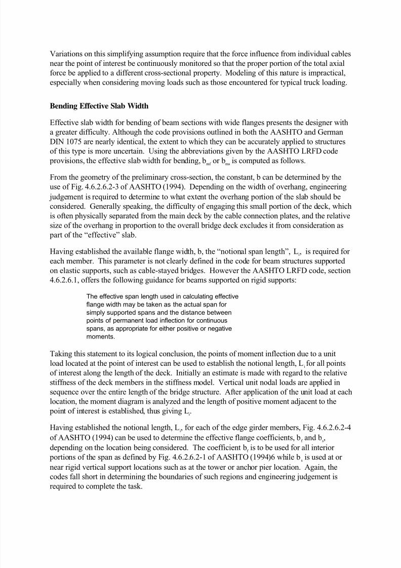
Figure 5 Effective Slab Width for Comparison Model
Findings from this comparison show that the methodology currently being employed gives
good results throughout the middle portion of both the back and main span of the structure.
The greatest area of inconsistency with the finite element model occurs in the slab stress near the anchor pier support of the back span and the center portion of the main span near the
closure area. These variations are largely due to the manner in which the axial portion of the
load and the effective slab width for axial load are dealt with in the current method of design.
In the region near the center of the main span, a reduced effective slab width is used for both
axial force and bending by the current method as can be seen in Fig. 5. A comparison of the
top of steel stress for the main span is shown in Fig. 6. Note that the results labeled T187-
Modified b_eff represent the stresses obtained using the proposed modified method in a
conventional direct stiffness “stick” model.
It should be noted that in both of these regions, the stress values obtained by the current method
are conservative in nature, but raise questions as to the appropriateness of the methods used for
an economic design solution.

7/23/2019 Comparison of Slab Participation Assumed for Design vs. FEA__Byers__Malmo__1999
http://slidepdf.com/reader/full/comparison-of-slab-participation-assumed-for-design-vs-feabyersmalmo1999 9/11
Figure 6 Top Flange Stress Comparison
Conclusions
In an age of ever-increasing complexity for the field of structural engineering, designers are
asked to perform more rigorous detailed investigations on atypical structures such as the cable-
stayed bridge. Therefore, the need to simplify broad categories of assumptions into a moredirect solution method is greater than ever.
In the early development of composite design methods for simple structures, generalizing
mathematical models were developed to explain such phenomena as shear lag and effective
breadth. These theoretical solutions, though exact, were dependent on multiple variables that
change with virtually every problem such as beam depth, flange width, span length, slab
thickness etc… Given the intricacy of the solution methods presented, simplifying assumptions
were needed to allow engineers to perform repetitive design tasks on “typical” structure types
without being burdened by the complexity of the intermediate solutions. Thus, design codes
were established that provided a vehicle for the engineer to safely establish intermediate
computations, such as effective flange width, so that more time and effort could be given to themore important “big-picture” items in the design.
Because of the high degree of indeterminacy presented by complex bridge structures like cable-
stayed bridges, direct mathematical theory becomes too complex to offer any practical
consideration for solution. Finite elements of an elastic continuum, such as the ones used in this
research, offer approximate solutions that can be used in a fashion similar to the early
mathematical models mentioned above. This research has provided a “first attempt” at
establishing a simplified method of analysis for determining the effective slab width to be used
in the design of composite cable-stayed bridges comprised of steel and concrete sections. At
the present time, no research of this kind has been previously recorded in the literature.

7/23/2019 Comparison of Slab Participation Assumed for Design vs. FEA__Byers__Malmo__1999
http://slidepdf.com/reader/full/comparison-of-slab-participation-assumed-for-design-vs-feabyersmalmo1999 10/11
Using the modified effective slab width described above, good correlation of the results are
obtained when comparing both stress and displacement between the simplified direct stiffness
models and the full finite element models. In addition, little difference exists in the results when
comparing the current method to that of the proposed modified method except as noted above.
Therefore, it appears the modified effective slab width method proposed provides a suitable tool
that can be expediently used by designers to predict both stress and deflection of compositecable-stayed bridges.
Based on the results of this research, it is recommended that the effective slab width for composite
cable-stayed bridges meeting the parameters and limitations described by Byers (1999) may be
accurately estimated using the guidelines presented in Fig. 4.
Further research into localized areas near the cable to deck connection and the portion of the deck
between the cables at the center of the main span will provide additional insight into design
parameters that can be implemented by engineers.
References
AASHTO (1994), LRFD Bridge Design Specification, American Association of State
Highway and Transportation Officials, First Edition.
D.D. Byers, “ Evaluation of Effective Slab Width for Composite Cable-Stayed Bridge Design”,
Ph.D. Dissertation, The University of Kansas, 1999
DEUTSCHE NORM, German DIN 1075, April, 1981, DIN 1072, Din 1076, Current.

7/23/2019 Comparison of Slab Participation Assumed for Design vs. FEA__Byers__Malmo__1999
http://slidepdf.com/reader/full/comparison-of-slab-participation-assumed-for-design-vs-feabyersmalmo1999 11/11
Produced by Congrex Sweden AB
International Associationfor Bridge and StructuralEngineering (IABSE)
Proceedings
IABSE Conference
Cable-Stayed Bridges- Past, Present and Future
The Öresund Construction Site, October 1998
Malmö, Sweden 2-4 June, 1999
Jointly organized by the Danish and Swedish Groups of IABSE
![[PPT]Grillage Analysis for Slab & Pseudo-Slab Bridge Decksenggprog.com/Downloads/Lectures/BridgeEngg/Lecture No. 3... · Web viewTitle Grillage Analysis for Slab & Pseudo-Slab Bridge](https://static.fdocuments.in/doc/165x107/5adedacf7f8b9afd1a8beaa6/pptgrillage-analysis-for-slab-pseudo-slab-bridge-no-3web-viewtitle-grillage.jpg)