COMPARISON OF OPTIMAL COSTS OF AXIALLY LOADED RC …
16
1 Assistant professor, B.E (Civil), M.E (Structures) Bannari Amman Institute of Technology, Faculty of Civil Engineering, Sathyamangalam, Erode District, India 2 Prof, B.E (Hons), M.Sc (Engg), Bannari Amman Institute of Technology, Faculty of Civil Engineering, Sathyamangalam, Erode District, India COMPARISON OF OPTIMAL COSTS OF AXIALLY LOADED RC TENSION MEMBERS USING INDIAN AND EURO STANDARDS N.KARTHIGA ALIAS SHENBAGAM 1 , N.ARUNACHALAM 2 Abstract: The aim of this study is to find the cost design of RC tension with varying conditions using the Artificial Neural Network. Design constraints were used to cover all reliable design parameters, such as limiting cross sectional dimensions and; their reinforcement ratio and even the beahviour of optimally designed sections. The design of the RC tension members were made using Indian and European standard specifications which were discussed. The designed tension members according to both codes satisfy the strength and serviceability criteria. While no literature is available on the optimal design of RC tension members, the cross-sectional dimensions of the tension membersfor different grades of concrete and steel, and area of formwork are considered as the variables in the present optimum design model. A design example is explained and the results are presented. It is concluded that the proposed optimum design model yields rational, reliable, and practical designs. Key Words: RC tension members, optimal design, optimization, loadings, neural networks, design model, Indian standards, Euro standards. 1. INTRODUCTION Reinforced concrete structures are ones made of two or more different materials:-, minimum weight has no meaning with respect to optimization. Optimization has been formulated as minimum cost. Large number of papers have been published on optimization of structures. However, only a small fraction of these deal with cost optimization of structures. For concrete structures, the objective function to be minimized should be cost, since they are made of more than one material. Tie members of trusses and tied arches, walls of rectangular tanks and bunkers, suspended roofs, cylindrical pipes, and walls of liquid retaining structures are some of the sample problems where tensile stresses develop. Traditional elastic approach and the limit state method can be useful for the design of such structures. Based on the elastic theory, the classical method is straight - forward in concept and application, while the limit state method, based on cracking behaviors of concrete, is not yet fully developed. IS 456:2000 and Euro codal specifications give due considerations for compression either direct or connected with bending and shear when the limit state method is working. However, it is silent on tension members. Therefore the working stress method is employed in this paper to explain the design of such members.
Transcript of COMPARISON OF OPTIMAL COSTS OF AXIALLY LOADED RC …

1 Assistant professor, B.E (Civil), M.E (Structures) Bannari Amman Institute of Technology, Faculty of Civil Engineering, Sathyamangalam, Erode District, India 2 Prof, B.E (Hons), M.Sc (Engg), Bannari Amman Institute of Technology, Faculty of Civil Engineering, Sathyamangalam, Erode District, India
COMPARISON OF OPTIMAL COSTS OF AXIALLY LOADED RC TENSION MEMBERS USING INDIAN AND
EURO STANDARDS
N.KARTHIGA ALIAS SHENBAGAM1, N.ARUNACHALAM2
Abstract: The aim of this study is to find the cost design of RC tension with varying conditions using the Artificial Neural Network. Design constraints were used to cover all reliable design parameters, such as limiting cross sectional dimensions and; their reinforcement ratio and even the beahviour of optimally designed sections. The design of the RC tension members were made using Indian and European standard specifications which were discussed. The designed tension members according to both codes satisfy the strength and serviceability criteria. While no literature is available on the optimal design of RC tension members, the cross-sectional dimensions of the tension membersfor different grades of concrete and steel, and area of formwork are considered as the variables in the present optimum design model. A design example is explained and the results are presented. It is concluded that the proposed optimum design model yields rational, reliable, and practical designs.
Key Words: RC tension members, optimal design, optimization, loadings, neural networks, design model, Indian standards, Euro standards.
1. INTRODUCTION Reinforced concrete structures are ones made of two or more different materials:-, minimum weight
has no meaning with respect to optimization. Optimization has been formulated as minimum cost.
Large number of papers have been published on optimization of structures. However, only a small
fraction of these deal with cost optimization of structures. For concrete structures, the objective
function to be minimized should be cost, since they are made of more than one material. Tie
members of trusses and tied arches, walls of rectangular tanks and bunkers, suspended roofs,
cylindrical pipes, and walls of liquid retaining structures are some of the sample problems where
tensile stresses develop. Traditional elastic approach and the limit state method can be useful for the
design of such structures. Based on the elastic theory, the classical method is straight - forward in
concept and application, while the limit state method, based on cracking behaviors of concrete, is
not yet fully developed. IS 456:2000 and Euro codal specifications give due considerations for
compression either direct or connected with bending and shear when the limit state method is
working. However, it is silent on tension members. Therefore the working stress method is
employed in this paper to explain the design of such members.

2. TENSION MEMBERS Vertical suspenders in a bowstring girder and the-, ring beam of a dome are some of the members
subjected to direct tensile forces. Many RC structural components such as walls of water tanks,
bunkers, silos, and counter forts of retaining walls are subjected to tensile force, in addition to
bending moments.
3. PREVIOUS LITERATURE Abobakr A.A.Aga, Fathelrahman M.Adam[1] (2015) in their paper explain the formation of
objective function for a frame in a detailed manner with the various constraints for each and every
element in a frame, and optimization is done with the help of ANN.-, The cost compared is the
actual manually calculated one with that of ANN, the difference between them is discussed and it is
found that ANN gives a better result than the manual design.
Anand Prakash. S.K. Agarwala..K.K. Singh[2] (1988) explain the optimal design considerably in a
simplified manner, handling the cost ratio of steel-to-concrete as a variable. The authors have
adopted this approach using modern computers, software and relatively simple optimization
techniques to obtain optimum design results for singly and doubly--reinforced beams, T-beams, and
columns, which are eccentrically loaded and the results and conclusions are then described in a
detailed manner.
ArunlfoLuevanos-Rojas (2016)[3], in their paper demonstrated the optimal design of the Singly
Reinforced Beam by creating a model and an analytic approach using ACI-318, considering two
criteria, with four different cases for minimum weight (Case 3,4) and minimum cost (Case1,2) and
it is concluded that for Case 1 the optimum section is very economical compared to other sections
that may be obtained using the standard design method. The optimum steel ratio is usually smaller
than the maximum ratio, ρmax, and greater than minimum ratio, ρmin. Cases 2, 3 and 4: The
optimum steel ratio is equal to the maximum ratio ρmax.If we analyze the mathematical results of
the standard design method and the optimal design method, they are equal.
S.A.Bhalchandra, P.K.Adsul[4], (2012) in their paper explained the design of simply supported
doubly reinforced beam with two types of loadings and the optimal cost solution is determined, in
addition to the serviceability conditions, with the help of the GRG approach and MATLAB.
Luisa Maria Gil Martin and Enrique Hernandez[1](2010) in their research work explain the optimal
positioning of the reinforcement area with the help of the latest computing tools, considering the
effect of the constraints with a suitable example which has bars on both sides, it saves the cost of
construction and improves the durability of structural construction.
100 N. KARTHIGA ALIAS SHENBAGAM, N. ARUNACHALAM

Chakrabarty-(1992) [5] in his paper made use of geometric programming and found the optimal
design of singly-reinforced rectangular concrete beams. The design variables considered are the
cross-section of the beam and the area of steel reinforcement. The main objective function was the
total cost of construction of the beam. He included the strength aspects in the design process for
bating optimal or minimal values but discounted the ductility and side constrains.
G Preethi and Prince G Arulraj[7]in their paper regarding different grades of concrete and steel,
determined the optimal total cost of the RC column by the use of MATLAB programming using
the fmincon SQL algorithm and found it to be a very effective approach for determining optimal
design.
N.S.Hadi[8](2002) in his paper gives a brief description about the application of ANN and the
different kinds of methods we can use and implement in structural engineering problems.
H.Sudarshana Rao and B. Ramesh Babu, (2006)[9], in their paper demonstrate the design of short
columns under biaxial bending with use of optimization techniques. In this paper, they used ANN
and GA. The results of biaxial columns are optimized by modified GA, the outputs are compared
and it is observed that the maximum difference between both methods is only 1.6%. The conclusion
is then made that a developed neural network model can provide a safe and economical outline for
the design of short columns under biaxial bending.
ImaRahmanian,YvesLucet, and Solomon Tesfamariam (2014)[10] in their paper describe the review
of optimal design of a RC beam by using various optimization techniques and a nonlinear approach
is determined which gives suitable, appropriate results.-, It is then checked against the manual
design in Excel, which gives a contribution of various design parameters to the overall cost of RC
beams.
Luisa Maria Gil Martin – Enrique Hernandez[11] (2010) in their research work explain about the
optimal positioning of the reinforcement area with the help of latest computing tools, considering
the effect of the constraints with a suitable example which has bars on both sides:-, it saves on the
cost of construction and improves the durability of structural construction.
GebrailBekdas, SinanMelihNigdeli (2012)[12] in their paper decsribe the optimization ofbeams using
HS and BA approaches respectively, and it is finally concluded that if the flexural moment is 300
kNm or more, doubly reinforced design is needed. The HS approach is not effective for 400 kNm
and 450 kNm flexural moments, because reinforcements are placed in two lines at the compressive
section of the beam. Optimum reinforcements placed in a single line were found for the BA and
TLBO approaches. Population based methods such as BA and TLBO are effective on the optimum
solution of the problem. As a conclusion, TLBO is a competitive algorithm for the optimum design
COMPARISON OF OPTIMAL COSTS OF AXIALLY LOADED RC TENSION MEMBERS USING... 101

of RC beams. Comparing to BA, TLBO is more on finding an optimum solution, and it is easy to
apply.
Sinan Melih Nigdeli, Gebrail Bekdaş (2016)[13] in their paper demonstrate the preliminary design
of RC continuous beams using ACI-318, from which the optimal cross--sections of beams are
acheived by using a random search technique, which in turn minimizes the cost of materials used in
the construction of continuous beams. It has been explained that the random search technique gives
an effective solution when compared with the other available techniques.
R. Deepan. et.al, March (2016)[14], state in their paper that the optimal design of RC beams is
carried out with two loading conditions, for central pointed load and for udl. The designs of the
beams and the constraints for optimal design have been carried out using the recommendation of
IS456:2000. Manually, the design has been done using MS Excel and verified using Non-traditional
Optimization techniques, and it is concluded that use of optimization techniques gives 98% optimal
results (over classical methods).
4. DESIGN OF A RC MEMBER SUBJECTED TO AXIAL
TENSION ONLY The following criteria are :
1. The total tension force is considered to be resisted by the reinforcement only.
2. The tensile stress in the reinforcement must be less than or equal to the allowable stress The
allowable stress in concrete of the transformed section must be less than or equal to the
allowable tensile stress to prevent excessive cracking as given in Clause B-2.1.1 of
Annexure B of IS456:2000
These criteria may be expressed as follows
Further,
where
T-axial tension face
Ast-area of steel reinforcement
Ac-area of concrete
fast- allowable tensile stress in steel
fa- allowable direct tensile stress in concrete
(4.1)
(4.2)
102 N. KARTHIGA ALIAS SHENBAGAM, N. ARUNACHALAM

4.1 DESIGN VARIABLES: The design example illustrated below gives the step by step procedure for the RC design of a
tension member with respect to the working stress method as per codal provisions of
IS456:2000.The grades of concrete used for the design are M25, M30, M35, M40, M45, M50 and
steel of grades Fe250, Fe415, Fe500, Fe550 resp in the case of IS code. In the case of Euro code, the
grades of concrete used for the design are M25, M30, M35, M40, M45, M50 and steel of grades
Fe235, Fe275, Fe355, Fe420,Fe460 resp. In both the cases the live loads used are 50kN, 100kN, 150kN
and 200kN.
4.2 WORKING STRESS METHOD: Design a tie member of a RCC structure subjected to a tensile force of 100kN including dead and
imposed loads. Assume M35 grade concrete and Fe250 steel.
fast-140MPa
fact-4MPa (as per IS 456:2000)
Modular ratio=m= =
STEP1: Calculation of Ast required:
The required area of tension reinforcement
STEP 2: Calculation of gross area of concrete section:
Required theoretical section is of size 144.5mm by 144.5mm.
(4.3)
(4.4)
(4.5)
(4.6)
COMPARISON OF OPTIMAL COSTS OF AXIALLY LOADED RC TENSION MEMBERS USING... 103

5. ARTIFICIAL NEURAL NETWORK
The objective function is to minimize the cost per unit length of the tension which is determined as
Total Cost = Cost of Concrete + Cost of Steel + Cost of Formwork
Total Cost = Cc Ac + Cs Aast+ Cf*Af
Total Cost = Cc (Ag – Ast) + Cs Ast + 4 Cfb
Ag and Ast are expressed in m2 units and b in meter units where,
Cc-Cost of concrete per unit volume (Rs/m3)
Cs-Cost of steel per unit volume (Rs/m3)
Cf-Cost of formwork per unit contact area (Rs/m2)
Af-Area of formwork in m2
b- size of square cross section in m
The optimization problem is to determine Ag and Ast to minimize equation (5.1). The problem is
solved for different values of fy, fck, and T to build a database through which the neural network is
trained, validated and tested in the following phase of the work.
6. NEURAL NETWORK MODELS FOR OPTIMUM DESIGN OF
RC TENSION MEMBERS
Five Hundred RC tension members were designed using the two codal provisions, and the total cost
(including the cost of formwork per unit length) of members has been estimated. The design has
been carried out with three different numbers of hidden layers, the results tabulated, and finally
concluded in the discussion is the best optimal solution.
(5.1)
104 N. KARTHIGA ALIAS SHENBAGAM, N. ARUNACHALAM

NEURAL NETWORK MODEL I
NEURAL NETWORK MODEL –II
Fig. 2. Neural network model with 8 nodes
NEURAL NETWORK III
Fig. 1. Neural network model with ten nodes
Fig. 3. Network model with six nodes
COMPARISON OF OPTIMAL COSTS OF AXIALLY LOADED RC TENSION MEMBERS USING... 105

6.1 TEST PROBLEMS The test result problems obtained from the different hidden layers are tabulated in the table with
some samples, and they are compared with the actual results of the tension member design by using
the Indian standards and the Euro Code Standards.
Table1: Results obtained from actual and neural network model
SI
.
N
o.
Inputs
Theore
tical
Result
Network Output IS
CodeInputs
Theoreti
cal
Result
Network Output Euro
Code
6
nodes
8
nodes
10
nodes
6
nodes
8
node
10
nodes
1
fck=25
b =162 162.6 162.1 161.53fck=25
b=166.8 166.1 164.0 163.9fy= 250 fy= 235
Pu=100 Ast =
714.28714.6 714.1 713.81
Pu=100 Ast=489.
3489.1 488.6 487.2
m=8 m=8
2
fck=30b = 158 158.8 158.1 157.81
fck=30b=158.56 158.3 157.8 156.5
fy= 415 fy= 275
Pu=100 Asc
=434.7434.6 432.0 433.51
Pu=100 Ast=418.
1417.9 417.5 416.4
m=6 m=6
3
fck=35 b =
151.3151.1 150.6 149.26
fck=35B=152.0 151.9 151.4 150.0
fy= 500 fy= 355
Pu= Asc=
363.363.4 362.9 361.6
Pu= 100 Ast=323.
9
323.7
1
323.2
3321.8
m=7 m=7
4
fck=40b= 138. 138.2 137.3 135.69
fck=40B=13.55
139.3
61
138.8
8136.8
fy= 550 fy= 420
Pu= Asc =
333.33333.1 332.6 331.26
Pu= 100 Ast=273.
80
237.6
1
237.1
3271.7
m=6 m=6
6.2 Theoretical results:
The influence of grades of steel and concrete on the required quantities of these two materials and
on the total cost, including the cost of the formwork of the RC tension members is given in Figures
4-11
106 N. KARTHIGA ALIAS SHENBAGAM, N. ARUNACHALAM
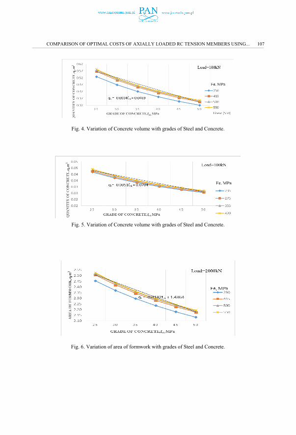
Fig. 4. Variation of Concrete volume with grades of Steel and Concrete.
Fig. 5. Variation of Concrete volume with grades of Steel and Concrete.
Fig. 6. Variation of area of formwork with grades of Steel and Concrete.
COMPARISON OF OPTIMAL COSTS OF AXIALLY LOADED RC TENSION MEMBERS USING... 107

Fig. 7. Variation of area of formwork with grades of Steel and Concrete.
Fig. 8. Variation of Total Cost with grades of Steel and Concrete.
Fig. 9. Variation of Total Cost with grades of Steel and Concrete.
108 N. KARTHIGA ALIAS SHENBAGAM, N. ARUNACHALAM

Fig. 10. Variation of Total Cost with �.
Fig. 11. Variation of Total Cost with �.
COMPARISON OF OPTIMAL COSTS OF AXIALLY LOADED RC TENSION MEMBERS USING... 109

REFERENCES 1. AbobakA.A.Aga, FathelrahmanM.Adam,“Design optimization of Reinforced concrete Frames” Open Journal
of Civil Engineering, Volumn 5,ppNo:74-83, doi:10.4236/ojce.2015.51008,ISSN No:Online: 2164-3172, 2015. 2. S.K. Anand Prakash, K.K. Agarwala Singh, “Optimum design of reinforced concrete sections”, Computers
and Structures, Volume30,Issue 4, pp.No 1009-1011, http://dx.doi.org/10.1016/0045-7949(88)90142-3, ISSN: 0045-7949, 1988.
3. ArunlfoLuevanos-Rojas, “Numerical experimentation for the optimal design of reinforced rectangular concrete beams for singly reinforced sections “, DYNA 83(196),pp.No.134-142, 2016.
4. P.K. Balachandra, S.Adsul., “Cost Optimization Of Doubly Reinforced Rectangular” International journal of Modern Engineering Research (IJMER)- Vol 2 Issue 5,pp.3939-3942, 2012.
5. Beams by Neural Networks, ASCE Journal of Structural Engineering, Vol. 127, No. 7, 2001,pp. 818-828. 6. Chakarnatty “Model for Optimal Design of Reinforced Concrete Beam” Journal of Structural Engineering Vol
118 (3) pp.No:447-451, 1992. 7. G. Preethi, Prince G. Arulraj “Optimal Design of Axially Loaded RC Column”, Bonfring International journal
of Industrial Engineering and Management Science, Vol 6 No.3 pp.No.78-81, 2016. 8. N.S. Hadi, Neural Networks Applications in Concrete structures, Computers and Structures, Vol. 81, pp.373-
381, 2002.9. H. Sudarsana Rao, B. Ramesh Babu, “Optimized column design using genetic algorithm based neural
networks” Indian Journal of Engineering & Materials Sciences, Vol 13, pp.No 503-511, 2006. 10. ImaRahmanian, YvesLucet, Solomon Tesfamariam “Optimal Design of reinforced concrete beams:Areview”,
Computers and Concrete”Vol.13,No.4, ppNo.457-482, 2014. 11. Luisa Mari a Gil-Martin Mark Aschheim Enrique Hernandez-Montes Mark Aschheim, “Optimal
reinforcement of RC columns for biaxial bending” Matrials and Structures, pp.no 1245-1256, 2010. 12. S. Mehta, “Cost Optimization of Concrete Beam Element - By Direct Exhaustive Search Method”, Indian
Journal of Engineering & Materials Sciences Vol. 13, pp. 503-511, 2006.13. M.Z. Cohn “limit state design of reinforced concrete structures for maximum yield safety:, Indian Concrete
Journal, Vol. 36, No.6, 1962. 14. M. Papadrakakis, N.D. Lagaros, “Soft Computing Methodologies for Structural optimization”, Applied soft
computing Vol (3), pp.283-300,2003 15. Salim T Yousif, Ikhlas S ALsaffar, Saddam M.Ahmed, “Optimum Design of Singly and Doubly Reinforced
Concrete rectangular beam sections: Artificial Neural Network”, Iraqi journal of Civil Engineering, Volume 6 No.3, 2010.
16. A. SaraBabiker, M. Fathelrahman. E. Abdelrahman, “ Design Optimization Of Reinforced Concrete Beams Using Artificial Neural Network” International Journal of Engineering Inventions, Volume 1, Issue 8,PP: 07-13, 2012.
17. Sinan Melih Nigdeli, Gebrail Bekdaş,”Optimum design of RC continuous beams considering unfavorable live-load distributions” KSCE Journal of Civil Engineering, Vol 20, Issue112, pp No. 1-7, 2016.
18. V.PETCU:” Optimal plastic moments reinforced concrete continuous beams” Indian Concrete Journal, V.36, No.3, March 1962, pp.110-113.
19. T. Yousif., M. Ahmed, “Optimum Design of Singly and Doubly Reinforced Concrete Rectangular Beam Sections: Artificial Neural Networks Application “,Iraqi Journal of Civil Engineering Vol. 6, No. 3, pp. 1-19,2006.
20. N. KarthigaShenbagam, Dr.N. Arunachalam “Least Cost Design of Axially Loaded Tension Members using Optimization Techniques” International Journal of Printing Packing and Allied Sciences, Volume 4 Issue 2, page No.1250-1259, 2016.
21. Ashok K Jain, Reinforced concrete Limit state design, Nem Chand & Bros, Roorkee, 2010. 22. B.C.Punmia, Ashok K Jain,Arun Kr Jain, Limit State Design of Reinforced concrete,Firewall Media,2007 23. Davis, L. Hand book of genetic algorithms. Van NostrandReinholt, New York. 1991. 24. Design Expert Systems, Computers and Structures, Vol. 54, No. 3,1995,pp. 367-375. 25. N. Krishnaraju, Advanced Reinforced concrete design, CBS Publishers and Distibutors, New Delhi,
Bangalore, 2009. 26. N. Krishnaraju, Reinforced concrete design, CBS Publishers and Distibutors, New Delhi, Bangalore, 2009. 27. A. Mukharjee, Deshpande., Application of Artificial Neural Networks in Structural 28. Mishra, A.K., &AkhilUpadhyay., Compression Design using ANN, ICI Journal, 2004, pp. 17-19.29. Nilson,Darwin and Dolan, “Design of Concrete Structures:, McGraw-Hill, 13th Edition,2004. 30. N.Subramanian,Design of Reinforced concrete Structures,Oxford University Press,2013 31. P.C.Varghese, Limit State Design of Reinforced concrete Structures,Prentice Hall of India Private Limited,
2008
110 N. KARTHIGA ALIAS SHENBAGAM, N. ARUNACHALAM

32. Rao S.S, Engineering Optimization Theory and Practice, New Age International publisher, 2009 33. S.Unnikrishnan Pillai, DevadosMenon, “Reinforced concrete Design Third edition Tata McGraw Hill,2009 34. The math works, MATLAB V6.5,24 prime way, Natick, MA 01760-1500,USA,2002. 35. ACI Committee 318, Building Code Requirements for Reinforced Concrete, American Concrete Institute,
Detroit 2005. 36. EN1992 I-I and EN1992-I-2, EUROCODE 2: Design of Concrete Structures Design of Concrete Structures
General Rules and rules for Buildings and Structural Fire Design. 37. IS456:2000, Code of Practice foe Plain and Reinforced Concrete, Bureau of Indian Standards , New Delhi 38. SP16:1980:Design Aids for IS456:2000
Received 03.11.2016
Revised 02.02.2017
LIST OF FIGURES AND TABLES:
Fig. 1. Neural Network model with 10 nodes.
Rys. 1. Model sieci neuronowej z dziesięcioma węzłami
Fig.2. Neural Network model with 8 nodes.
Rys. 2. Model sieci neuronowej z ośmioma węzłami
Fig.3. Neural Network model with 6 nodes.
Rys. 3. Model sieci z sześcioma węzłami
Fig.4. Variation of concrete volume with grades of steel and concrete.
Rys. 4 Wariacja objętości betonu w zależności od klasy stali i betonu.
Fig.5. Variation of concrete volume with grades of steel and concrete.
Rys. 5 Wariacja objętości betonu w zależności od klasy stali i betonu.
Fig.6. Variation of area of formwork with grades of steel and concrete.
Rys. 6 Wariacja obszaru szalowania w zależności od klasy stali i betonu.
Fig.7. Variation of area of formwork with grades of steel and concrete.
Rys. 7 Wariacja obszaru szalowania w zależności od klasy stali i betonu.
Fig.8. Variation of Total cost with grades of steel and concrete.
Rys. 8 Wariacja kosztu całkowitego w zależności od klasy stali i betonu.
Fig.9. Variation of Total cost with grades of steel and concrete.
Rys. 9 Wariacja kosztu całkowitego w zależności od klasy stali i betonu.
Fig.10. Variation of Total cost with �.
Rys. 10 Wariacja kosztu całkowitego w zależności od �.
Fig.11. Variation of Total cost with �.
Rys. 11 Wariacja kosztu całkowitego w zależności od �.
Tab. 1. Results obtained from actual and neural network models.
Tab. 1. Wyniki uzyskane z rzeczywistego modelu i modelu sieci neuronowej
COMPARISON OF OPTIMAL COSTS OF AXIALLY LOADED RC TENSION MEMBERS USING... 111

PORÓWNANIE OPTYMALNYCH KOSZTÓW OSIOWO OBCIĄŻONYCH ZBROJONYCH
CIĘGIEN Z WYKORZYSTANIEM STANDARDÓW EUROPEJSKICH I INDYJSKICH
Słowa kluczowe – zbrojone cięgna, optymalna konstrukcja, optymalizacja, obciążenia, sieci neuronowe, model projektowy, standardy indyjskie, standardy europejskie.
Niniejsza praca została poświęcona optymalnemu projektowi zbrojonych cięgien. Zaprojektowano blisko pięćset
zbrojonych cięgien zgodnie ze standardem indyjskim IS 456:2000 i standardem europejskim EN1992, ręcznie przy
użyciu arkuszy kalkulacyjnych Microsoft Excel. Uwzględnione zmienne stanowią charakterystyczną wytrzymałość
betonu, wahającą się od 25 do 50N/mm2 dla obu specyfikacji kodału? (codal?). Wytrzymałość plastyczna stali waha się
pomiędzy 250, 415, 500 i 550 N/mm2 w przypadku IS 456:2000 i pomiędzy 235, 275, 355, 420 i 460 N/mm2
w przypadku standardu europejskiego. Obciążenie osiowe wahało się od 500kN do 3000 kN. Teoretyczne wyniki
uzyskane na podstawie ręcznego projektu zostały wyjaśnione poniżej.
Na podstawie Rysunku 4 i 5 można stwierdzić, że wraz ze wzrostem klasy betonu, wymagana objętość betonu maleje,
a wariacja staje się nieliniowa. W przypadku stali Fe 250, wariacja może być przybliżona za pomocą linii prostej
o następującym równaniu: qc = -0.0034fck + 0.0469 w oparciu o IS 456:2000, natomiast dla standardu europejskiego,
równanie jest następujące: qc=-0.002fck+0.027. Oczywisty jest również fakt, że wymagana objętość betonu dla
konkretnej klasy betonu wzrasta wraz ze wzrostem klasy stali.
Na podstawie Rysunku 6 i 7 można stwierdzić, że wraz ze wzrostem klasy betonu, wymagany obszar szalowania się
zmniejsza, ponieważ rozmiar cięgien się zmniejsza, a wariacja staje się nieliniowa. Dla klasy stali Fe 415, 500 i 550,
wariacja może być przybliżona za pomocą linii prostej o następującym równaniu: qf = -0.0182fck + 1.4363.
W przypadku standardu europejskiego, równanie jest następujące: qf=-0.014fck+1.351
Na podstawie Rysunku 6 można stwierdzić, że wraz ze wzrostem klasy betonu, koszt konstrukcji cięgna zbrojonego
maleje, zgodnie z poniższymi równaniami:
C = -6.063fck + 624.7 dla klasy stali Fe250
C = -6.2773fck + 578.04 dla klasy stali Fe415
C = -6.3316fck +566.14 dla klasy stali Fe500
C = -6.354fck + 561.08 dla klasy stali Fe550
Na podstawie Rysunku 7 można stwierdzić, że wraz ze wzrostem stosunku � kosztów stali do kosztów betonu, koszt
konstrukcji cięgna zbrojonego maleje dla różnych klas betonu.
Na podstawie podejścia teoretycznego i podejścia ANN zastosowanych przez autorów, stwierdzono, że:
1. Wraz ze wzrostem klasy betonu, wymagana objętość betonu maleje, wnioski są wyciągane, a wymagany
obszar szalowania się zmniejsza.
2. Wraz ze wzrostem klasy betonu, całkowity koszt cięgna zbrojonego maleje.
3. Wraz ze wzrostem wartości �, koszt konstrukcji cięgna zbrojonego maleje dla wszystkich klas betonu.
4. Wraz ze wzrostem klasy stali, koszt konstrukcji (koszt betonu i stali) cięgna zbrojonego maleje.
5. Wraz ze wzrostem klasy betonu, koszt cięgna zbrojonego maleje.
112 N. KARTHIGA ALIAS SHENBAGAM, N. ARUNACHALAM

Sztuczna inteligencja jest dziedziną nauki, która obejmuje badania, projektowanie oraz zastosowanie sztucznej
inteligencji w dziedzinie informatyki. Tradycyjne metody modelowania i optymalizacji złożonych systemów
strukturalnych wymagają ogromnych zasobów komputerowych, jak również problemów związanych ze sztuczną
inteligencją, które często mogą stanowić cenne alternatywy dla skutecznego rozwiązywania problemów inżynierii
lądowej. Niniejsza praca zawiera krótki opis ostatniej opracowanej metody i teorii w rozwijającym się kierunku
zastosowań sztucznej inteligencji w inżynierii lądowej, takie jak obliczenia ewolucyjne, sieci neuronowe, rozmyte
systemy, systemy eksperckie, rozumowanie, klasyfikacja i nauka, jak również inne, takie jak teoria chaosu, algorytm
„cuckoo search”, algorytm „firefly”, inżynieria oparta na wiedzy oraz symulowane wyżarzanie. Praca zawiera przegląd
postępów w zakresie sztucznej inteligencji oraz jej zastosowania w inżynierii lądowej.
ANN jest zbiorem systemu opartego na działaniu biologicznych sieci neuronowych. Dane wejściowe są przesyłane
do sieci neuronowej i uzyskuje się odpowiednią pożądaną docelową odpowiedź. Błąd składa się z różnicy pomiędzy
pożądanym wyjściem i wejściem systemu. W niniejszej pracy, metoda wstecznej propagacji ANN została wykorzystana
w celu określenia optymalnej wartości funkcji kosztów.
Projektant konstrukcji ma na celu znalezienie optymalnego rozwiązania dla projektu konstrukcji. Optymalne
rozwiązanie dla całkowitego kosztu konstrukcji cięgien zbrojonych jest związane z sumą trzech kosztów, takich jak
koszt betonu, koszt stali oraz koszt szalowania. Dzięki zastosowaniu nietradycyjnych technik, takich jak ANN,
zmiennych wejściowe, które stanowiły charakterystyczną wytrzymałość betonu i stali, obciążeniu cięgna zbrojonego
oraz wartości stosunku modularnego, ukryte warstwy zostały zmienione na trzy typy, takie jak sześć węzłów, osiem
węzłów i dziesięć węzłów, odpowiednio. Funkcja wagi jest obliczana i normalizowana. Wartości wejściowe są badane
w celu uzyskania optymalnej wartości dla powierzchni przekroju brutto i stali. Wreszcie, na podstawie różnych badań
ukrytych węzłów stwierdzono, że wraz ze wzrostem liczby ukrytych węzłów uzyskujemy bardziej optymalną wartość w
porównaniu z rzeczywistym projektem w standardzie indyjskim iS456:2000 i standardzie europejskim. Wyniki
uzyskane w oparciu o wyjścia generowane przez sztuczne modele sieci neuronowych, w odniesieniu do wyników
teoretycznych, okazały się mieścić w zadowalającym zakresie. Zbadano wpływ klasy betonu i stali na całkowity koszt
cięgien zbrojonych i wyciągnięto wnioski przydatne dla praktycznych zastosowań.
COMPARISON OF OPTIMAL COSTS OF AXIALLY LOADED RC TENSION MEMBERS USING... 113