
COMPARISON OF NATURAL CONVECTION HEAT EXCHANGERS …
21
COMPARISON OF NATURAL CONVECTION HEAT EXCHANGERS FOR SOLAR WATER HEATING SYSTEMS TECHNICAL REPORT Jane Davidson and Wei Liu Department of Mechanical Engineering University of Minnesota Minneapolis, MN 55455 September 15, 1998 1
Transcript of COMPARISON OF NATURAL CONVECTION HEAT EXCHANGERS …
COMPARISON OF NATURAL CONVECTION HEAT EXCHANGERS FOR SOLAR WATER HEATING SYSTEMS
TECHNICAL REPORT
Jane Davidson and Wei Liu Department of Mechanical Engineering
University of Minnesota Minneapolis, MN 55455
September 15, 1998
1

This report was prepared as an account of work sponsored by an agency of the United States Government. Neither the United States Government nor any agency thereof, nor any of their employees, makes any warranty, express or implied, or assumes any legal liability or responsibility for the accuracy, completeness, or use- fulness of any information, apparatus, product, or proctss disclosed, or represents that its use would not infringe privately owned rights, Reference herein to any spe- cific commercial product, process, or service by trade name, trademark, manufac- turer, or otherwise does not necessarily constitute or imply its endorsement, mom- mendation. or favoring by the United States Government or any agency thereof. T’he views and opinions of authors exptessed herein do not necessarily state or reflect thosc of the United States Government or any agency thereof.

DISCLAIMER
Portions of this document may be illegible in electronic image products. Images are produced from the best available original document.
INTRODUCTION
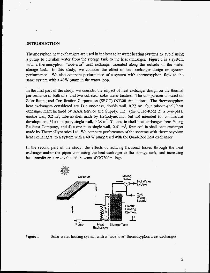
Thermosyphon heat exchangers are used in indirect solar water heating systems to avoid using a pump to circulate water from the storage tank to the heat exchanger. Figure 1 is a system with a thermosyphon “side-arm” heat exchanger mounted along the outside of the water storage tank. In this study, we consider the effect of heat exchanger design on system performance. We also compare performance of a system with thermosyphon flow to the same system with a 40W pump in the water loop.
In the first part of the study, we consider the impact of heat exchanger design on the thermal performance of both one- and two-collector solar water heaters. The comparison is based on Solar Rating and Certification Corporation (SRCC) OG300 simulations. The thermosyphon heat exchangers considered are 1) a one-pass, double wall, 0.22 m2, four tube-in-shell heat exchanger manufactured by AAA Service and Supply, Inc., (the Quad-Rod) 2) a two-pass, double wall, 0.2 m2, tube-in-shell made by Heliodyne, Inc., but not intended for commercial development, 3) a one-pass, single wall, 0.28 m2, 31 tube-in-shell heat exchanger fi-om Young Radiator Company, and 4) a one-pass single-wall, 0.61 m2, four coil-in-shell heat exchanger made by ThermoDynamics Ltd. We compare performance of the systems with thermosyphon heat exchmgers to a system with a 40 W pump used with the Quad-Rod heat exchanger.
In the second part of the study, the effects of reducing fiictional losses through the heat exchanger and/or the pipes connecting the heat exchanger to the storage tank, and increasing heat transfer area are evaluated in terms of OG300 ratings.
- .... .
li ‘L Mixing Valve
t8-e Valve
Hat Water to User
Cold Water s UPPlY
-Electric Heating Elemeni
T’
Hat Water ’to User
Cold Water
t
Figure 1 Solar water heating system with a “side-arm” thermosyphon heat exchanger.
2

DESCRIPTION OF THE SYSTEMS
Table .1 describes components of the systems excluding the heat exchangers. In the larger system, two collectors are connected in parallel. To compare heat exchangers fairly, we fixed the collector flow rate at 0.03 kg/s, the highest flow rate for which experimental data were available for the ThermoDynamics heat exchanger. The Young Radiator was tested with a collector flow rate of 0.05 kg/s. We do not expect this slightly higher flow rate to significantly affect performance because heat transfer is limited by heat transfer on the thermosyphon side of the heat exchanger.
The doubly pumped heat exchanger is modeled with a constant UA of 52 W/"C. This value was calculated using published forced convection heat transfer coefficients for a collector flow rate of 0.03 kg/s and a water flow rate of 0.08 kg/s. We assumed turbulent flow in the tubes although the Reynolds number is 1200. We felt this decision was justified by the inlet conditions and the addition of the helical coils in the tubes. If laminar flow heat transfer correlations are used, UA is 21 W/"C. We assumed perfect contact between the two tubes in the double wall. The water flow rate was estimated by matching the pump curves of a 40W single speed pump to the pressure drop characteristics of the water loop with the Quad-Rod heat exchanger.
Table 1. Specification of Modeled Systems
I Area / Panel I 3m2 I Efficiency = 0.725 - 3.2 W/m2."C ( ATD )
- 0.022 W/m2-OC2 ( AT~D Flow Rate PumD 40W
0.03kg/s (Young Radiator Tube-in-Shell Heat Exchanger, 0.05 kg/s)
Heat Exchanger Variable UA 52 W/"C Tank 0.246 m3 , 10 nodes 0.246 m3 . 6 nodes
J Pump I None 40W I
3

Quad-Rod Heat Exchanger
A sketch of a single-pass, double-wall, four tube-in-shell heat exchanger (Quad-Rod) manufactured by AAA Solar Service and Supply, Inc. of Albuquerque, NM is shown in Figure 2. Cool water enters fiom the bottom on the shell side and exits near the top. The hot glycol mixture enters the top manifold and exits the lower manifold. The double wall assembly has a small gap between the two tubes that allows for leak detection. A helical wire was placed inside each of the tubes with the intent to enhance heat transfer. The exterior heat transfer area is 0.22 m2.
This heat exchanger is also used in the doubly pumped system.
Figure 2
Shell O.D. - 5.40 -
Section A-A Shell cross-section
All Units in cm
Schematic of the one-pass, double-wall, four tube-in-shell heat exchanger. (AAA Service and Supply, Inc.)
4

c
Two-Pass Tube-in-Shell Heat Exchanger
A two-pass, double-wall, tube-in-shell heat exchanger, supplied by Heliodyne, Inc. of Richmond, CA, is shown in Figure 3. Water flow is on the shell side. The glycol mixture enters and exits on the top of the heat exchanger. The heat exchanger is rifled inside the tubes and knurled on the exterior tube surface in an attempt to increase the heat transfer coeEcients on each side. Heat transfer area is 0.2 m2.
1.58 cm I.D. Norand
(Rifled on Interior) 115.67 cm
cm
Figure 3. Schematic of the two-pass, double-wall, tube-in-she11 heat exchanger with enhanced heat transfer surfaces. (Heliodyne, Inc.)
5
I
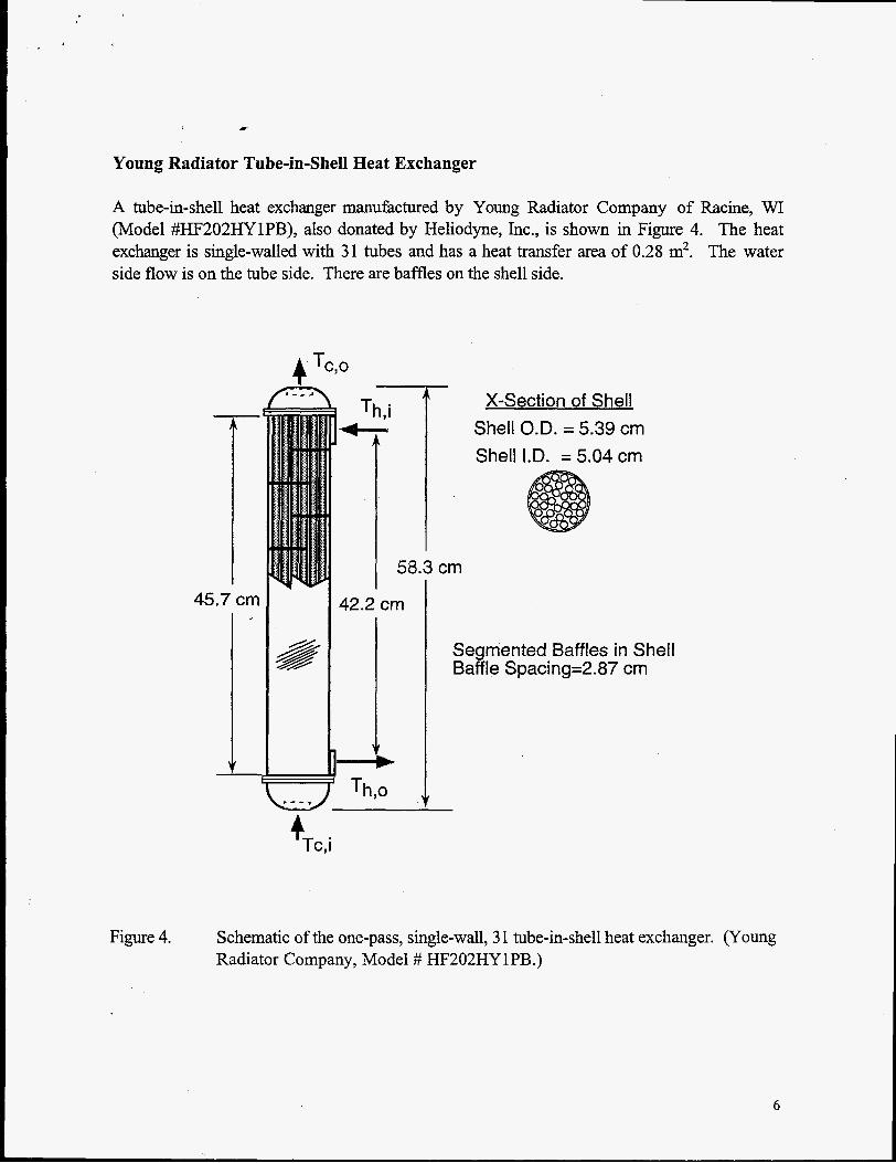
Young Radiator Tube-in-Shell Heat Exchanger
A tube-in-shell heat exchanger manufactured by Young Radiator Company of Racine, WI (Model #HF202HYlPB), also donated by Heliodyne, Inc., is shown in Figure 4. The heat exchanger is single-walled with 31 tubes and has a heat transfer area of 0.28 m2. The water side flow is on the tube side. There are baffles on the shell side.
45.7 cm
V
A X-Section of Shell Shell O.D. = 5.39 cm Shell I.D. = 5.04 cm
Th,i
I 56.3 cm
42.2 cm
i Th,o
4 Tc, i
Segmented Baffles in Shell Baffle Spacing=2.87 cm
Figure 4. Schematic of the one-pass, single-wall, 3 1 tube-in-shell heat exchanger. (Young Radiator Company, Model # HF202HYlPB.)
6

ThermoDynamics Coil-in-Shell Heat Exchanger
A coil-in-shell design, manufactured by ThermoDynamics Ltd. (Dartmouth, Novia Scotia, Canada), is shown in Figure 5. The thermal and hydraulic performance were measured at the University of Waterloo (Fraser et al., 1992; Fraser et al., 1993; Fraser et al., 1995) and University of Kovia Scotia (Allen and Ajele, 1994a; Allen and Ajele, 1994b). This commercially available heat exchanger is single-walled and has four helical coils running the length of the heat exchanger. The glycol mixture flows inside the tubes. The heat transfer area is 0.61 m2.
Th,i
i I
41 cm
Inlet Header for coils
x-Section of Shell Shell O.D. = 10.8 cm
i - ) T c , o (1.91 cm Diameter) Shell I.D. = 10.2 cm
Coiled Tube Dimensions Tube I.D. = 0.46 cm / Tube O.D. = 0.64 cm
Diameter of Coils 2.54 cm Coil #I
Coil #2 4.14 cm Coil #3 6.04 cm Coil #4 7.95 cm
3- Tc,i (1.27 cm Diameter)
Outlet Header for coils
Figure 5. Schematic of the one-pass, single-wall, four coil-in-shell heat exchanger. (ThermoDynamics Ltd.)
7

RESULTS
Measured Pressure Drop and UA Correlations
The TRNSYS OG300 model requires two empirical correlations: shear pressure drop across the heat exchanger as a function of thermosyphon flow rate and UA as a function of Prandtl, Reynolds and Grashof numbers. The correlations for the three tube-in-shell heat exchangers were obtained at the University of Minnesota. The test facility consists of a simulated collector loop in which 50/50 ethylene glycol is heated with an electric boiler, and a water loop that includes the heat exchanger, water storagekeating tank and a cold water supply. The correlations for the coil-in-shell heat exchanger were obtained from the test data at University of Waterloo and University of Novia Scotia.
Measured values of UA were determined with the equation,
mcp(Th,i -Th,o) LMTD
UA =
Where UA is in units of W/"C.
Using the measured values of UA, a correlation of the form
UA = P1 Rep2 P f3 GP4
was determined using the statistical software SYSTAT. In this analysis, w- a sumed the exponent P3 = 0.43. This value was chosen based on prior work with other heat exchangers. The dimensionless parameters in the correlation are,
V Pr = -
a g m D h 3
V 2 Gr = ,
where AT is the temperature difference between the hot and cold inlet temperatures, and
pVDh P
Re=-.
(3)
(4)
The fluid properties used to calculate the dimensionless parameters are based on the average of the hot and cold inlet temperatures.
8

The shear pressure drop on the water side of the heat exchangers can be expressed as a function of thermosyphon mass flow rate:
AP = c1 m2 +c2m, (6)
where AP is in units of Pa, and m is in units of kgls.
The pressure drop and UA correlations for the thermosyphon heat exchangers are in Table 2. Also shown in the table are the average values of UA for the thermosyphon heat exchangers with one collector during the OG300 simulation.
Table 2. Pre
Exchanger
Quad-Rod Tube-in-Shell
Two-Pass Tube-in-Shell
Young Radiator
Tube-in-Shell
Thermo- Dynamics
CoiI-in-S he11
Pumped Quad-Rod
;sure Drop and UA Correlations for Heat Exchangers Heat Collector UA
Area Rate Transfer Flow (W/OC)
on2) (kg/s)
0.22 0.03 AT (1.21*.03)~~-(() 1433 ( 1 3 ) ~ ~ (0 2 M ()Up+) 43
R2=0.89; Average UA = 43 WIoC
(0.07f10.03)Re(0 17%) 0 3 4 3 (0 3m 02)pr0 43 0.20 0.03 AT
R2=0.90; Average UA = $2 Wl°C
( 9 . ~ . 5 ) ~ ~ - ( O ( f f i ~ ) ( l I ) ~ ~ (I) 233)02)p+143 0.28 0.05 AT
R2=0.97; Average UA = 151 W/"C
(1 0.5fl . 4 ) ~ ~ ( 0 ( h M 024-3 (0 203) 03)p+) 43 0.61 0.03 A T
R2=0.80; Average UA = 220 W/"C
0.22 0.03 52
AP (Pa)
124602 m 2 - 310.5 m
44300 m + 203 m
164000 m 2 + 1620 m
49000 m + 350 m
124602m2-310.5m
06300 Ratings
The SRCC OG300 simulations for the hypothetical one- and two-collector(s) systems are compared in Figures 6 and 7. Numerical values are given in Table 3. Solar Energy Factor (SEF) = Load/(Auxiliary + Parasitic Energy). Solar Fraction (SF) is the portion of the total water heating load provided by solar energy, ie., SF = Net SolarLoad.
For the one-collector system, solar energy factors and solar fractions are similar for the four systems with thermosyphon heat exchangers. Solar Energy Factor ranges from 1.4 for the Quad-Rod and two-pass tube-in-shell heat exchangers to 1.6 for the coil-in-shell heat
9
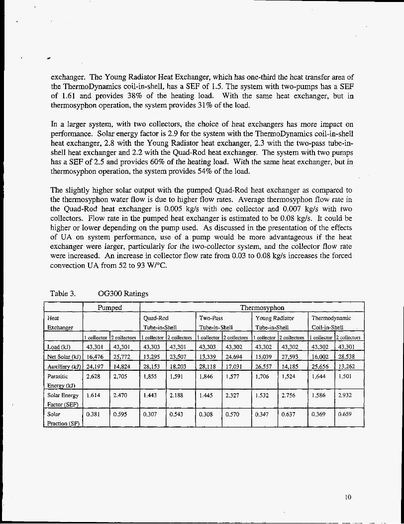
exchanger. The Young Radiator Heat Exchanger, which has one-third the heat transfer area of the ThermoDynamics coil-in-shell, has a SEF of 1.5. The system with two-pumps has a SEF of 1.61 and provides 38% of the heating load. With the same heat exchanger, but in thermosyphon operation, the system provides 3 1 % of the load.
In a larger system, with two collectors, the choice of heat exchangers has more impact on performance. Solar energy factor is 2.9 for the system with the ThermoDynamics coil-in-shell heat exchanger, 2.8 with the Young Radiator heat exchanger, 2.3 with the two-pass tube-in- shell heat exchanger and 2.2 with the Quad-Rod heat exchanger. The system with two pumps has a SEF of 2.5 and provides 60% of the heating load. With the same heat exchanger, but in thermosyphon operation, the system provides 54% of the load.
The slightly higher solar output with the pumped Quad-Rod heat exchanger as compared to the thermosyphon water flow is due to higher flow rates. Average thermosyphon flow rate in the Quad-Rod heat exchanger is 0.005 kg/s with one collector and 0.007 kg/s with two collectors. Flow rate in the pumped heat exchanger is estimated to be 0.08 kg/s. It could be higher or lower depending on the pump used. As discussed in the presentation of the effects of UA on system performance, use of a pump would be more advantageous if the heat exchanger were larger, particularly for the two-collector system, and the collector flow rate were increased. An increase in collector flow rate from 0.03 to 0.08 kg/s increases the forced convection UA from 52 to 93 W/"C.
Table 3. OG300 Ratings
Parasitic 2,628 2,705 1,855 1,591 1,846 1,577 1,706 1,524 1,644 1,501 Energy (kJ)
Solar Energy 1.614 2.470 1.443 2.188 1.445 2.327 1.532 2.756 1.586 2.932 Factor (SEF) Solar 0.381 0.595 0.307 0.543 0.308 0.570 0.347 0.637 0.369 0.659 Fraction (SF)
10

3 .5
3
2.5
L,
9 p z
0 5 a 1.5 5i
A
m
I
0.5
0
Pumped Q u ad -R od T w O - P ~ S S Young Radia tor T h e r m o D y n a m i c H e a t Exchanger Tu be- in-S hel l T u be- in-S hell One-Pass Coi l - in-Shel l
Tube- in-Shel l
Figure 6. OG300 Solar energy factors for one-collector and two-collector systems.
0.8
0.7
0 . 6
0.5
0.4
0.3
0.2.
0.1
0
P u m p e d Quad-Rod T u b e - Two-Pass T u b e - Young Radia tor T h e r m o D y n a m i c s H e a t Exchanger in-Shel l in-S hel l 0 ne-Pass T u b e - Coi l - in-S hel l
in -Shel l
Figure 7. OG300 Solar fractions for one-collector and two-collector systems.
11

Effect of Heat Exchanger Pressure Drop and Size
To better illustrate the effects of heat exchanger pressure drop and area on system performance, we repeated the OG300 simulations using modified correlations for the Quad- Rod tube-in-shell heat exchanger. The empirical correlations were modified with simple multiplicative constants “a” and “b”,
UA (W/”C) = a * ( 1.21 Re -‘.I4 Gr AT o‘26 Pr 0.43 )7
hp (Pa) = b * ( 124602 m2 - 310.5 m),
We used multiplicative factors from 0.2 to 8 for UA and from 0.1 to 6 for pressure drop. Multiplying the measured UA correlation by the factor “a” is equivalent to modifying the area, but not the geometry, of the heat exchanger. In OG300 simulations, we found that UA is modified only slightly by changes in the values of Reynolds, Grashof and Prandtl numbers as system operating conditions changed. A more fundamental approach to determining the effect of heat exchanger geometry would be to model the heat transfer process in various geometries rather than using the empirical correlations. This approach is beyond the scope of this project.
The pIots in Figures 8 and 9 of SEF and SF versus the multiplicative factor “a” show the effect of increasing or decreasing UA for various heat exchanger pressure drop values. The nominal UA is 43 W/”C with one collector and 45 W/”C with two collectors. The effect of changing the pressure drop correlation multiplier “b” while fixing the UA correlation is shown in Figures 10 through 13. Data are plotted for one- and two-collector systems.
One-Collector Svstem As shown in Figures 8 and 9, the thermosyphon heat exchanger is adequately sized for a system with one-collector. A reduction in size would adversely affect system performance by increasing collector operating temperature. Increasing the UA has little effect on the OG300 rating. When the UA correlation is increased 4-fold, from 43 W/”C to 165 W/”C, water flow rate increases less than 10%. With flow rates an order of magnitude less than the pumped flow value (0.005 kg/s versus 0.08 kg/s) energy stored in the water tank remains low.
Note that if a pump is used with this heat exchanger, it would be advantageous to increase heat transfer surface area. For a larger heat exchanger, the difference between performance of the pumped and thermosyphon systems would be greater. When the UA of the doubly pumped heat exchanger is arbitrarily increased from 52 to 95 W/”C, SEF increases from 1.6 to 1.8 with one collector. The increase in heat transfer area has more impact on system performance when a pump is used because of the higher water flow rate.
12
3.1
2.9
2.7
2.5 3 g 2.3
bl
0
h g 2.1
F5 L
0 [A
-
1.1 0
Figure 8.
0.7
0.6
0 .s
B P I .d
2 0.4 L - m
0 . 3
0.2
0.1 0
Figure 9.
-o-b = 0.7(1 collector) *b = 1.0(1 col lector) 4 b = l S ( 1 collector)
-e-b = 0.7(2 col lectors) --+E- b = 1.0(2 col lectors)
5 6 7 8 1 2 3 4 a
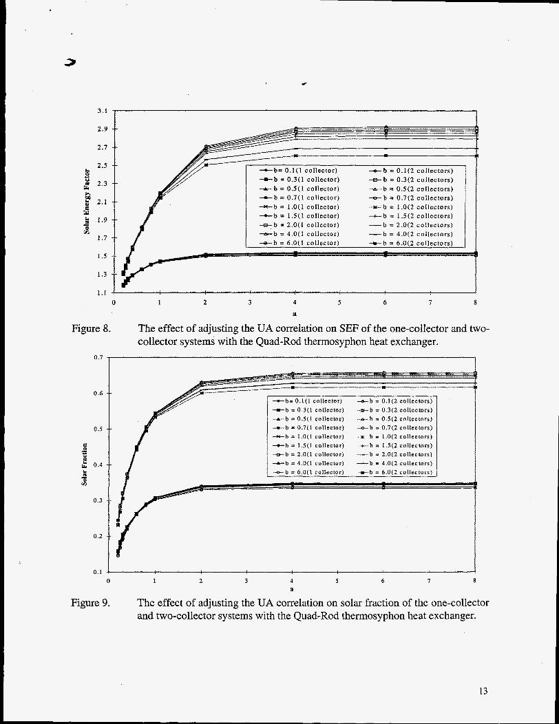
The effect of adjusting the UA correlation on SEF of the one-collector and two- collector systems with the Quad-Rod thermosyphon heat exchanger.
-b= 0.1(1 collector) + b = 0.3(1 collector)
-o-b = 0.1(2 collectors) -..rr.-b = 0.3(2 collectors)
-t- b = 0.5(1 collector) -o-b = 0.7(1 collector) + b = 1.0(1 collector) +b = l S ( 1 collector) -m-b = 2.0(1 collector) + b = 4.0(1 collector)
.-e- b = 0 . 5 ( 2 collectors) 4 b = 0.7(2 collectors) + b = 1.0(2 collectors) - -+ -b = l S ( 2 collectors) -b = 2.0(2 collectors) -b = 4.0(2 collectors)
1 2 3 4 5 6 7 8 a
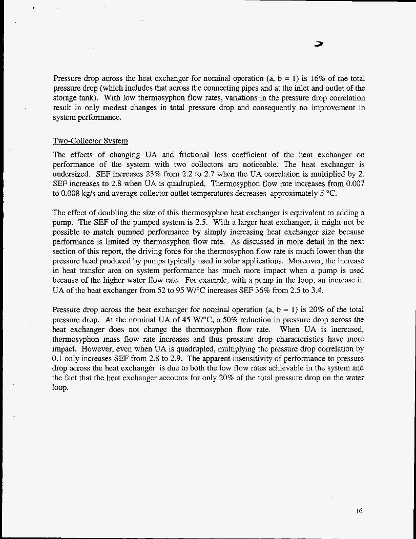
The effect of adjusting the UA correlation on solar fraction of the one-collector and two-collector systems with the Quad-Rod thermosyphon heat exchanger.
13

1.55 I 1
1.5 1. a = 0.2 (1 col lector)
I a = 0.25 (1 col lector) a = 0.3 (1 col lector)
p a = 0.4 ( 1 col lector) x a = 0.6 ( 1 col lector) 0 a = 0.8 ( 1 col lector) o a = 1 .O ( 1 col lector) A a = 2.0 (1 col lector) o a = 4.0 (1 col lector) - a = 6.0 ( I collector) Y a = 8.0 ( 1 col lector)
Figure 10. The effect of adjusting the pressure drop correlation on solar energy factor of the one-collector system with the Quad-Rod thermosyphon heat exchanger.
0.35
0.30
8 0.25 .* c1 0
6 k P - 5: 0.20
0.15
0.10
a = 0.2 (1 col lector) a a = 0.25 (1 collector) A a = 0.3 (1 col lector) c a = 0.4 ( 1 col lector) x a z 0.6 ( 1 col lector) e a = 0.8 (1 col lector) o a = 1.0 (1 col lector) A a = 2.0 (1 collector) o a = 4.0 ( I col lector) - a = 6.0 ( 1 col lector) x a = 8.0 ( 1 col lector)
3 4 5 6
b 0 1 2
Figure 11. The effect of adjusting the pressure drop correlation on solar fraction of the one-collector system with the Quad-Rod thermosyphon heat exchanger.
14

I I
c 2.3 t- - - 5 I p 2.1 0 C 2 1.9
2 1.7
1.5
1.3
1.1
m -
1 2 3 4 5 6 0 b
Figure 12.
0.70
0.65
0.60
OS5
0.50
E 0.45 ’ 0.40
.- E +
2
0.35
0.30
0.25
0.20 0
+ a = 0.2 (2 col lectors)
I a = 0.25 (2 col lectors)
& a = 0.3 ( 2 col lectors)
a a = 0.4 ( 2 col lectors)
A a = 0.6 (2 col lectors)
n a = 0.8 (2 col lectors)
o a = 1 .O (2 col lectors)
o a = 2.0 (2 col lectors)
+ a = 4.0 (2 col lectors)
o a = 6.0 (2 col lectors) - a = 8.0 (2 collectors)
The effect of adjusting the pressure drop correlation on solar energy factor of the two-collector system with the Quad-Rod thermosyphon heat exchanger.
l j
1 2 3 4
b 5 6
* a = 0.2 (2 collectors) 1 a = 0.25 ( 2 collectors) A a = 0.3 ( 2 collectors) - a = 0.4 (2 collectors) a B = 0.6 (2 collectors) o B = 0.8 ( 2 collectors) D a = L ,0 ( 2 cullectors) o a = 2.0 (2 collectors) + a = 4.0 (2 collectors)
= 6 . 0 ( 2 collectors) - p = 8.0 ( 2 collectors)
Figure 13. The effect of adjusting the pressure drop correlation on solar fraction of the two-collector system with the Quad-Rod thermosyphon heat exchanger.
.
Pressure drop across the heat exchanger for nominal operation (a, b = 1) is 16% of the total pressure drop (which includes that across the connecting pipes and at the inlet and outlet of the storage tank). With low thermosyphon ffow rates, variations in the pressure drop correlation result in only modest changes in total pressure drop and consequently no improvement in system performance.
Two-Collec tor Svs tem The effects of changing UA and frictional loss coefficient of the heat exchanger on performance of the system with two collectors are noticeable. The heat exchanger is undersized. SEF increases 23% from 2.2 to 2.7 when the UA correlation is multiplied by 2. SEF increases to 2.8 when UA is quadrupled. Thermosyphon flow rate increases from 0.007 to 0.008 kg/s and average collector outlet temperatures decreases approximately 5 "C.
The effect of doubling the size of this thermosyphon heat exchanger is equivalent to adding a pump. The SEF of the pumped system is 2.5. With a larger heat exchanger, it might not be possible to match pumped performance by simply increasing heat exchanger size because performance is limited by thermosyphon flow rate. As discussed in more detail in the next section of this report, the driving force for the thermosyphon flow rate is much lower than the pressure head produced by pumps typically used in solar applications. Moreover, the increase in heat transfer area on system performance has much more impact when a pump is used because of the higher water flow rate. For example, with a pump in the loop, an increase in UA of the heat exchanger from 52 to 95 W/"C increases SEF 36% from 2.5 to 3.4.
Pressure drop across the heat exchanger for nominal operation (a, b = 1) is 20% of the total pressure drop. At the nominal UA of 45 W/"C, a 50% reduction in pressure drop across the heat exchanger does not change the thermosyphon flow rate. When UA is increased, thermosyphon mass flow rate increases and thus pressure drop characteristics have more impact. However, even when UA is quadrupled, multiplying the pressure drop correlation by 0.1 only increases SEF from 2.8 to 2.9. The apparent insensitivity of performance to pressure drop across the heat exchanger is due to both the low flow rates achievable in the system and the fact that the heat exchanger accounts for only 20% of the total pressure drop on the water loop.
16

Effect of Reducing Total Pressure Drop
Pressure drop in the water loop can be reduced by design of connecting piping and inlet and outlet to the water storage tank. The water loop in this analysis has some components needed for the experiments that would not be present in an actual installation. To determine if system performance could be improved by eliminating some of these components, additional OG300 simulations were carried out with the total pressure drop reduced as much as 90%. Solar energy factors for the one and two-collector systems are plotted in Figure 14 as a function of the ratio of adjusted total pressure drop to the nominal value. This plot confirms that in terms of an OG300 Rating, shear pressure drop is not the critical factor for improving performance because of the low driving force for thermosyphon flow.
There is an inherent limitation to flow rate on the thermosyphon side due to the maximum possible pressure head difference between the storage tank and the water in the heat exchanger. The flow on the water side of the side-arm heat exchangers is driven by this hydrostatic pressure difference,
where H is the vertical distance between the port where cold water exits the bottom of the storage tank and the port where hot water returns from the heat exchanger. The thermosyphon flow rate can be approximated from a balance of this pressure difference and frictional losses in the water loop, ,
To better understand the hydrostatic pressure differences that can be expected in a solar water heater, the hydrostatic pressure difference between the water in the storage tank and the water in the heat exchanger is plotted in Figure 15 as a function of the average heat exchanger water temperature for two temperature distributions in a storage tank. The highest pressure difference would exist when the tank is filled with cold water and the heat exchanger is at some maximum temperature. Consider the case when the wilter in the tank is 20 "C and the heat exchanger contains water at 90 "C. The hydrostatic pressure difference would be less than 450 Pa for a standard height tank. In a more realistic system, in which an electric heating element is used to heat the top third of the tank to 54 "C, the hydrostatic pressure difference drops by approximately 50 Pa. To put these values in perspective, a 40 W pump provides 20,000 Pa with the Quad-Rod heat exchanger in the water loop.
17

C
2.40
2.20
2.00 0 * 2
B L
La
!? 1.80 W - rn 1.60
I .40
I .20
--&-.Total Pressure Drop adjusted, N o m i n a l UA, 1 collector
+-Total Pressure Drop adjusted, N o m i n a l UA, 2 collectors
-2_.-___
............. .... ................... ----.----.+ ~ * - 2
0.1 0.2 0.3 0.4 0.5 0.6 0.7 0.8 0.9 1
~ p ~ ~ p , , , , , , ,
Figure 14. The effect of adjusting the total pressure drop on solar energy factor of the one- and two-collector system with the Quad-Rod thermosyphon heat exchanger.
450
400
h 350
$ 300 0. a 250 S >
200
4 150 U * 100 I
?!
2
.- - u .- w
2
50
0 20 30 40 50 60 70 80 90
Average Heat Exchanger Temperature, O C
Figure 15. Theoretical hydrostatic pressure difference for the storage tank at two thermal conditions.
18

c
SUMMARY
Our study of thermosyphon heat exchangers has resulted in accurate models of solar water heating systems that use this type of heat exchanger. The model requires an empirical correlation of overall heat transfer area product (UA) with Reynolds, Prandtl and Grashoff numbers on the thermosyphon side of the heat exchanger and an expression of shear pressure drop as a function of thermosyphon mass flow rate. In this study, we determined these correlations for four heat exchangers. The effects of using these heat exchangers in systems with both one and two collectors was assessed by comparing simulated SRCC OG300 daily values of Solar Energy Factor and Solar Fraction. Performance is similar when one collector is used. With two collectors, the Young Radiator single wall tube-in-shell and the single-wall ThermoDynamic coil-in-shell are better choices than the smaller double-wall heat exchangers.
In a more systematic consideration of the effects of pressure drop and heat transfer area, we varied UA and shear pressure drop of one of the double-wall thermosyphon heat exchangers by multiplying the respective correlations by a constant. Over a wide range of values, we found that Solar Energy Factor and Solar Fraction are relatively insensitive to efforts to reduce frictional losses in the piping and heat exchanger. This result is at first counter intuitive because thermosyphon flow rate is determined by a pressure balance across the water loop. However, because the maximum possible difference in hydrostatic pressure in the water tank and the heat exchanger is low, water flow rates are an order of magnitude lower than those in pumped systems. Consequently, shear pressure drop is less sensitive to changes in loss coefficients.
The effect of UA is more pronounced, particularly in larger two collector systems. The heat exchanger should be adequately sized to transfer the collected energy to the storage tank and keep the temperature of the fluid entering the collector near that of the water at the bottom of the tank. The advantage of adequately sizing the heat exchanger outweighs any accompanying increase in frictional loss coefficient.
The decision to use thermosyphon flow in the water loop must take into account capital, operating and maintenance costs as well as thermal performance. When the heat exchanger is adequately sized, pumped systems will generally provide higher solar fractions because of significantly higher water flow rates.
19