
Comparison of Mechanical Properties of TIG and … of Mechanical Properties of TIG and MIG Welding...
6
Comparison of Mechanical Properties of TIG and MIG Welding using Aluminum Alloy Saurabh Kumar Khotiyan1, Ravi Goel2, Ankit Saini3 1,2,3 Assistant professor, Quantum School of Technology, Roorkee, [email protected], [email protected] [email protected] Abstract TIG (Tungsten Inert Gas) welding and MIG (Metal Inert Gas) welding are most important welding techniques in industry point of view. Aluminium is a common material used in all industries. Aluminum has second rank in case of annual consumption after steel. Pure aluminum melts at 6600C, and its alloys at lower temperature. The crystal structure of aluminum is FCC, and it is very ductile material. In this paper the study is done on welding technique (TIG or MIG) to find which welding technique is the best for aluminium alloy. The comparison is done on the basis of mechanical properties of the welded joint of TIG and MIG welding on aluminium alloy. It was observed that TIG welding has better in Tensile strength, hardness, impact strength. Key Words: TIG, MIG, A-6061. 1 INTRODUCTION: Welding is a process where joining is done by application of heat. There are many types of welding existing to weld different metals. Aluminium is on second number in terms of annual consumption however steel have first position. The market value of aluminium increasing at very fast rate, welding of aluminium also became a major consideration in industries. There are a number of techniques for joining the aluminium alloys. The selection of welding process depends on various factors, which influence the joining of the material a lot. These factors are material and geometry of the parts to be joined, requirement of joint strength, type of joint, number of parts to be joined, appeal for the aesthetic look of the joint and service conditions like moisture, temperature, inert atmosphere and corrosion. Table 1 Physical and Mechanical properties of aluminum (Varley, 1970) International Journal of Scientific & Engineering Research Volume 8, Issue 10, October-2017 ISSN 2229-5518 472 IJSER © 2017 http://www.ijser.org IJSER
Transcript of Comparison of Mechanical Properties of TIG and … of Mechanical Properties of TIG and MIG Welding...
Comparison of Mechanical Properties of TIG
and MIG Welding using Aluminum Alloy
Saurabh Kumar Khotiyan1, Ravi Goel2, Ankit Saini3
1,2,3 Assistant professor, Quantum School of Technology, Roorkee,
[email protected], [email protected] [email protected]
Abstract
TIG (Tungsten Inert Gas) welding and MIG (Metal Inert Gas) welding are most important welding techniques in industry point of view.
Aluminium is a common material used in all industries. Aluminum has second rank in case of annual consumption after steel. Pure aluminum
melts at 6600C, and its alloys at lower temperature. The crystal structure of aluminum is FCC, and it is very ductile material. In this paper the
study is done on welding technique (TIG or MIG) to find which welding technique is the best for aluminium alloy. The comparison is done on the
basis of mechanical properties of the welded joint of TIG and MIG welding on aluminium alloy. It was observed that TIG welding has better in
Tensile strength, hardness, impact strength.
Key Words: TIG, MIG, A-6061.
1 INTRODUCTION:
Welding is a process where joining is done by
application of heat. There are many types of welding
existing to weld different metals. Aluminium is on
second number in terms of annual consumption however
steel have first position. The market value of aluminium
increasing at very fast rate, welding of aluminium also
became a major consideration in industries. There are a
number of techniques for joining the aluminium alloys.
The selection of welding process depends on various
factors, which influence the joining of the material a lot.
These factors are material and geometry of the parts to
be joined, requirement of joint strength, type of joint,
number of parts to be joined, appeal for the aesthetic
look of the joint and service conditions like moisture,
temperature, inert atmosphere and corrosion.
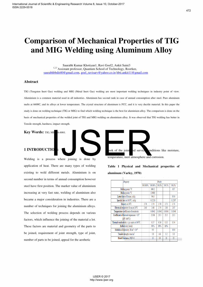
Table 1 Physical and Mechanical properties of
aluminum (Varley, 1970)
International Journal of Scientific & Engineering Research Volume 8, Issue 10, October-2017 ISSN 2229-5518
472
IJSER © 2017 http://www.ijser.org
IJSER
2. TUNGSTEN INERT GAS (TIG)
WELDING:
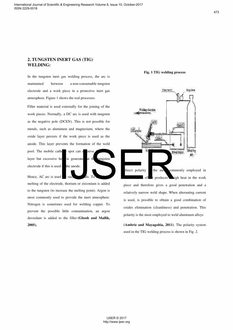
In the tungsten inert gas welding process, the arc is
maintained between a non-consumable tungsten
electrode and a work piece in a protective inert gas
atmosphere. Figure 1 shows the real processes.
Filler material is used externally for the joining of the
work pieces. Normally, a DC arc is used with tungsten
as the negative pole (DCEN). This is not possible for
metals, such as aluminum and magnesium, where the
oxide layer persists if the work piece is used as the
anode. This layer prevents the formation of the weld
pool. The mobile cathode spot can disperse the oxide
layer but excessive heat is generated at the tungsten
electrode if this is used as the anode.
Hence, AC arc is used for such materials. To avoid the
melting of the electrode, thorium or zirconium is added
to the tungsten (to increase the melting point). Argon is
most commonly used to provide the inert atmosphere.
Nitrogen is sometimes used for welding copper. To
prevent the possible little contamination, an argon
deoxidant is added to the filler (Ghosh and Mallik,
2005).
Fig. 1 TIG welding process
Direct polarity is the most commonly employed in
GTAW. This effect produces a high heat in the work
piece and therefore gives a good penetration and a
relatively narrow weld shape. When alternating current
is used, is possible to obtain a good combination of
oxides elimination (cleanliness) and penetration. This
polarity is the most employed to weld aluminum alloys
(Ambriz and Mayagoitia, 2011). The polarity system
used in the TIG welding process is shown in Fig. 2.
International Journal of Scientific & Engineering Research Volume 8, Issue 10, October-2017 ISSN 2229-5518
473
IJSER © 2017 http://www.ijser.org
IJSER
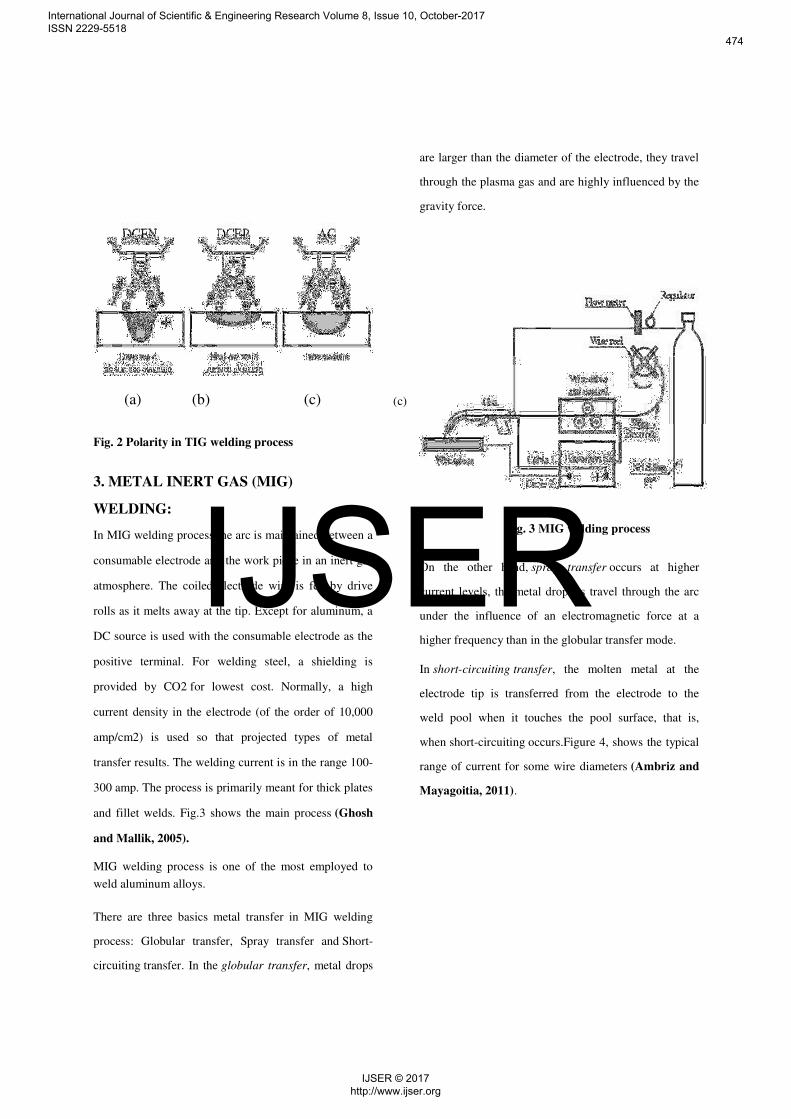
(a) (b) (c) (c)
Fig. 2 Polarity in TIG welding process
3. METAL INERT GAS (MIG)
WELDING:
In MIG welding process the arc is maintained between a
consumable electrode and the work piece in an inert gas
atmosphere. The coiled electrode wire is fed by drive
rolls as it melts away at the tip. Except for aluminum, a
DC source is used with the consumable electrode as the
positive terminal. For welding steel, a shielding is
provided by CO2 for lowest cost. Normally, a high
current density in the electrode (of the order of 10,000
amp/cm2) is used so that projected types of metal
transfer results. The welding current is in the range 100-
300 amp. The process is primarily meant for thick plates
and fillet welds. Fig.3 shows the main process (Ghosh
and Mallik, 2005).
MIG welding process is one of the most employed to
weld aluminum alloys.
There are three basics metal transfer in MIG welding
process: Globular transfer, Spray transfer and Short-
circuiting transfer. In the globular transfer, metal drops
are larger than the diameter of the electrode, they travel
through the plasma gas and are highly influenced by the
gravity force.
Fig. 3 MIG welding process
On the other hand, spray transfer occurs at higher
current levels, the metal droplets travel through the arc
under the influence of an electromagnetic force at a
higher frequency than in the globular transfer mode.
In short-circuiting transfer, the molten metal at the
electrode tip is transferred from the electrode to the
weld pool when it touches the pool surface, that is,
when short-circuiting occurs.Figure 4, shows the typical
range of current for some wire diameters (Ambriz and
Mayagoitia, 2011).
International Journal of Scientific & Engineering Research Volume 8, Issue 10, October-2017 ISSN 2229-5518
474
IJSER © 2017 http://www.ijser.org
IJSER
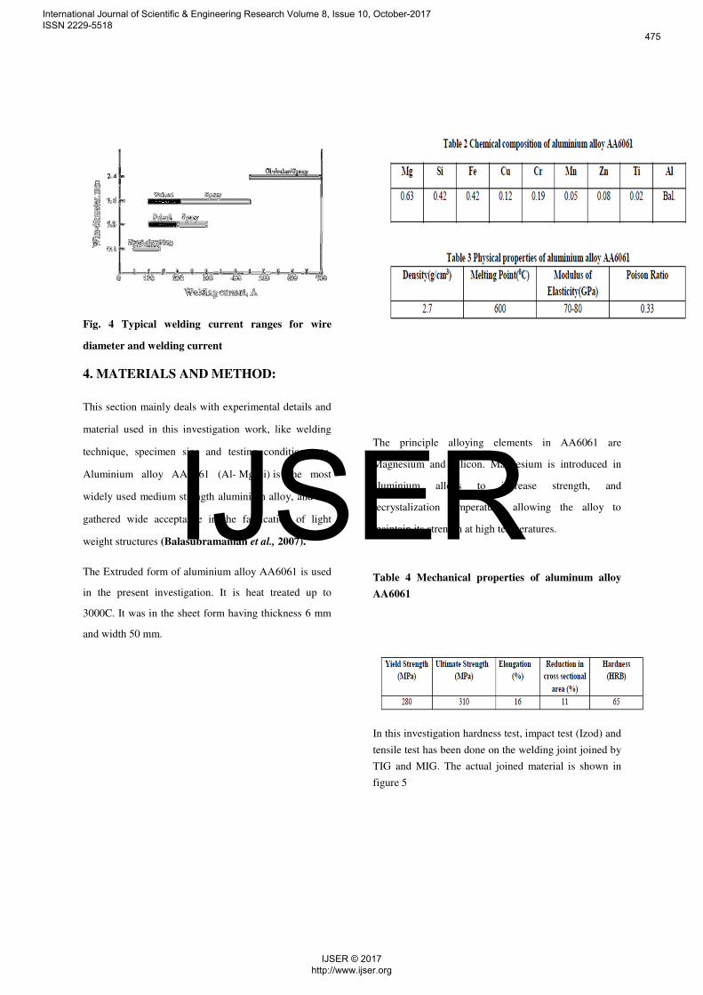
Fig. 4 Typical welding current ranges for wire
diameter and welding current
4. MATERIALS AND METHOD:
This section mainly deals with experimental details and
material used in this investigation work, like welding
technique, specimen size and testing conditions etc.
Aluminium alloy AA6061 (Al- Mg-Si) is the most
widely used medium strength aluminium alloy, and has
gathered wide acceptance in the fabrication of light
weight structures (Balasubramanian et al., 2007).
The Extruded form of aluminium alloy AA6061 is used
in the present investigation. It is heat treated up to
3000C. It was in the sheet form having thickness 6 mm
and width 50 mm.
The principle alloying elements in AA6061 are
Magnesium and Silicon. Magnesium is introduced in
aluminium alloys to increase strength, and
recrystalization temperature, allowing the alloy to
maintain its strength at high temperatures.
Table 4 Mechanical properties of aluminum alloy
AA6061
In this investigation hardness test, impact test (Izod) and
tensile test has been done on the welding joint joined by
TIG and MIG. The actual joined material is shown in
figure 5
International Journal of Scientific & Engineering Research Volume 8, Issue 10, October-2017 ISSN 2229-5518
475
IJSER © 2017 http://www.ijser.org
IJSER
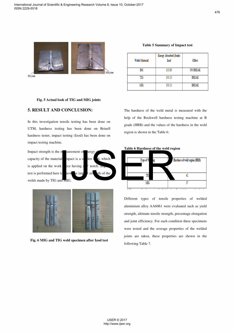
Fig. 5 Actual look of TIG and MIG joints
5. RESULT AND CONCLUSION:
In this investigation tensile testing has been done on
UTM, hardness testing has been done on Brinell
hardness tester, impact testing (Izod) has been done on
impact testing machine.
Impact strength is the measurement of energy absorbing
capacity of the material. Impact is a sudden load, which
is applied on the work piece having a V notch. Impact
test is performed here to know the impact strength of the
welds made by TIG and MIG.
Fig. 6 MIG and TIG weld specimen after Izod test
Table 5 Summary of Impact test
The hardness of the weld metal is measured with the
help of the Rockwell hardness testing machine at B
grade (HRB) and the values of the hardness in the weld
region is shown in the Table 6:
Table 6 Hardness of the weld region
Different types of tensile properties of welded
aluminium alloy AA6061 were evaluated such as yield
strength, ultimate tensile strength, percentage elongation
and joint efficiency. For each condition three specimens
were tested and the average properties of the welded
joints are taken, these properties are shown in the
following Table 7.
International Journal of Scientific & Engineering Research Volume 8, Issue 10, October-2017 ISSN 2229-5518
476
IJSER © 2017 http://www.ijser.org
IJSER
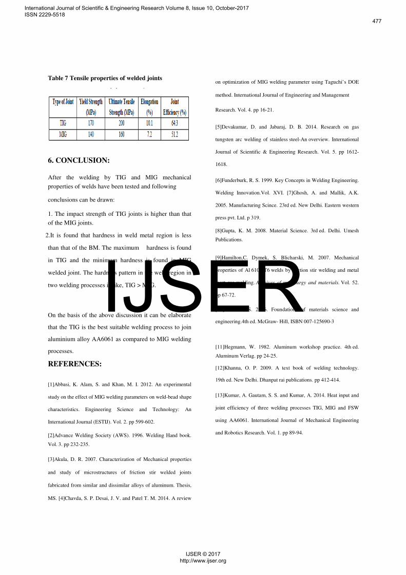
Table 7 Tensile properties of welded joints
6. CONCLUSION:
After the welding by TIG and MIG mechanical
properties of welds have been tested and following
conclusions can be drawn:
1. The impact strength of TIG joints is higher than that
of the MIG joints.
2.It is found that hardness in weld metal region is less
than that of the BM. The maximum hardness is found
in TIG and the minimum hardness is found in MIG
welded joint. The hardness pattern in the weld region in
two welding processes is like, TIG > MIG.
On the basis of the above discussion it can be elaborate
that the TIG is the best suitable welding process to join
aluminium alloy AA6061 as compared to MIG welding
processes.
REFERENCES:
[1]Abbasi, K. Alam, S. and Khan, M. I. 2012. An experimental
study on the effect of MIG welding parameters on weld-bead shape
characteristics. Engineering Science and Technology: An
International Journal (ESTIJ). Vol. 2. pp 599-602.
[2]Advance Welding Society (AWS). 1996. Welding Hand book.
Vol. 3. pp 232-235.
[3]Akula, D. R. 2007. Characterization of Mechanical properties
and study of microstructures of friction stir welded joints
fabricated from similar and dissimilar alloys of aluminum. Thesis,
MS. [4]Chavda, S. P. Desai, J. V. and Patel T. M. 2014. A review
on optimization of MIG welding parameter using Taguchi’s DOE
method. International Journal of Engineering and Management
Research. Vol. 4. pp 16-21.
[5]Devakumar, D. and Jabaraj, D. B. 2014. Research on gas
tungsten arc welding of stainless steel-An overview. International
Journal of Scientific & Engineering Research. Vol. 5. pp 1612-
1618.
[6]Funderburk, R. S. 1999. Key Concepts in Welding Engineering.
Welding Innovation.Vol. XVI. [7]Ghosh, A. and Mallik, A.K.
2005. Manufacturing Scince. 23rd ed. New Delhi. Eastern western
press pvt. Ltd. p 319.
[8]Gupta, K. M. 2008. Material Science. 3rd ed. Delhi. Umesh
Publications.
[9]Hamilton,C. Dymek, S. Blicharski, M. 2007. Mechanical
properties of Al 6101-T6 welds by friction stir welding and metal
inert gas welding. Archives of metallurgy and materials. Vol. 52.
pp 67-72.
[10]Hashemi, S. 2006. Foundations of materials science and
engineering.4th ed. McGraw- Hill, ISBN 007-125690-3
[11]Hegmann, W. 1982. Aluminum workshop practice. 4th ed.
Aluminum Verlag. pp 24-25.
[12]Khanna, O. P. 2009. A text book of welding technology.
19th ed. New Delhi. Dhanpat rai publications. pp 412-414.
[13]Kumar, A. Gautam, S. S. and Kumar, A. 2014. Heat input and
joint efficiency of three welding processes TIG, MIG and FSW
using AA6061. International Journal of Mechanical Engineering
and Robotics Research. Vol. 1. pp 89-94.
International Journal of Scientific & Engineering Research Volume 8, Issue 10, October-2017 ISSN 2229-5518
477
IJSER © 2017 http://www.ijser.org
IJSER