Comparison of Full and Partial Admission Flow Fields in · Comparison of Full and Partial Admission...
34
Comparison of Full and Partial Admission Flow Fields in the Simplex Turbine Daniel J. Dorney, Lisa W. Griffin and Douglas L. Sondak NASA Marshall Space Flight Center Applied Fluid Dynamics Analysis Group MSFC, AL 35812 10 September 2001 https://ntrs.nasa.gov/search.jsp?R=20030000731 2019-04-01T08:29:20+00:00Z
Transcript of Comparison of Full and Partial Admission Flow Fields in · Comparison of Full and Partial Admission...

Comparison of Full and Partial Admission Flow Fields in
the Simplex Turbine
Daniel J. Dorney, Lisa W. Griffin and Douglas L. SondakNASA Marshall Space Flight Center
Applied Fluid Dynamics Analysis GroupMSFC, AL 35812
10 September 2001
https://ntrs.nasa.gov/search.jsp?R=20030000731 2019-04-01T08:29:20+00:00Z
Outline @
Motivation
Flow code description - CORSAIR
- Capabilities
- Future directions
Results
- Full admission Simplex turbine
- Partial admission Simplex turbine
Conclusions
10/22/01 2

Motivation
Determine the effects of partial admission flow on:
- rotor performance as a function of circumferentiallocation
- unsteady rotor loading
Provide an efficient technique for determining
turbine performance
10/22/01 3

Flow Code Capabilities - I
CORSAIR
- Unsteady time-dependent equations of motion
- Full Navier-Stokes, thin-layer Navier-Stokes or Euler
- Variable fluid properties (Cp, gamma)
Third-order spatial diseretization of inviseid fluxes
- Roe's scheme
Second-order spatial diseretization of viscous fluxes
- Standard central differences
Second-order temporal accuracy
Multi-block O-H grid topology
- O-grids around airfoils and in tip clearance regions
- H-grids for remainder of flow field and nozzles
- Well-suited for medium-to-fine grain parallel simulations
10/22/01 4

Flow Code Capabilities - II
• Turbulence models
- Highly-modified Baldwin-Lomax model
Transition models
- Abu-Ghannam and Shaw (natural)
- Mayle (natural)
- Modified Roberts' correlation (bubble)
Boundary conditions
- Steady and unsteady inlet and exit
- Specified wall temperature or heat flux
- Film cooling/mass injection
- Actuator disk
- Component linking
Grid Motion
- Arbitrary translation/rotation
- Blade vibration
10/22/01 5

Flow Code Capabilities - III
MPI and OpenMP used for parallel simulations
- decomposition by blade row
- decomposition by blade passage
- decomposition by O- and H-grids
- decomposition by component
- user specified decomposition
Graphical User Interface
- Grid generation
- Flow solver
- Error checking
- Design page
- User's manual/help facility
- Post-processing
Miscellaneous capabilities
- Conjugate heat transfer capability
- Provides unsteady pressure file for stress analysis
- Provide Fourier decomposition of unsteady pressures
- Will run on any Unix, Linux or Windows NT platform
10/22/01 6

CORSAIR Future Directions
Modifying code for pump geometries
- incorporating incompressible flow physics
Incorporate two-phase flow modeling
Incorporate cavitation modeling
10/22/01 7

Simplex Turbine Simulations
Objective - determine the effects of partial admission
on the rotor unsteady load and performance as afunction of circumferential location
Full-Admission simulation (FA)
- 1 nozzle and 8 rotors modeled
- 750,000 grid points
- 8 full cycles (one complete rotor revolution) completed
Partial-Admission simulation (PA)
- 6 nozzles and 95 rotors modeled
- 7 million grid points
- 0.95 revolutions completed
- PA-IN- in region of nozzle flow
- PA-OUT - outside the region of nozzle flow
10/22/01 8

Simplex Turbine Rotors
10/22/01 9

Simplex Turbine Nozzles
= iiiiiiiiiiiiiiiiiiiiiiiiiiiiiiiiiiiiiiiiiiiiiiiiiiiiiiiiiiiii
iiiiiiii
10/22/01 10

Computational Grids - Rotor
.... _ ........ • .... ,,,,,4------_------ ......... ------,+++++++
:::-3_: Z Z_L'::Z+++)_++_ :::: :::::
_Z_......_ .......
_ ==_ _ _ _ ...........................................................
++}_+ :rrr-_rrr_
:+r _+r+ ------_------ _- ............
................_, .... iiiiiil
......._..............._ ....................._............
................._ ......
......., _,_Z Z Z_ ................................................
10/22/01 11

Nozzle/Rotor Interface - Mach Number (PA)
10/22/01 12

Instantaneous Mach Number- Nozzle
FULL ADMISSION PARTIAL ADMISSION
10/22/01 13

Instantaneous Mach Number- Nozzle
FULL ADMISSION PARTIAL ADMISSION
10/22/01 14

Instantaneous Mach Number
FULL ADMISSION PARTIAL ADMISSION
10/22/01 15

Instantaneous Mach Number- Rotor Exit
FULL ADMISSION PARTIAL ADMISSION
10/22/01 16

P/Pt
Unsteady Rotor Pressure Envelopes (FA)
11.7% Span
0,3 \
0.2
0.1
D 0.2 0.4
X/C
P/Pt
03
0.2
0.1
50.0% Span
0.6 0.8 0 0.2 0.4 0.6 0,8 1
X/C
...... Minimum
........ Maximum
........... Time-AvgP/Pt
10/22/01 X/C 1'7

Unsteady Rotor Pressure Envelopes (PA-IN)
P/Pt
0.3
0._
0.
13.3% Span
y %%
0 0.2 0.4 0.6 0._
X/C
...... Minimum
........ Maximum
........... Time-AvgP/Pt
P/Pt
0,4
03
0.:
0,]
0.4_--o,._ 50.0% Span
0,2.
0.1
00
%
86.7% Span
0.2, 0.4 0:6 O,g I
10/22/01 X/C 18

Unsteady Rotor Pressure Envelopes (PA-OUT)
P/Pt
o.1 o,i
0.08
o.(3_
o04
0.02
oo
13.3% Span
, _ 1 \
#
,. .[ • J; .A :1 _ Jl J,3.2 0.4 0.6 0.8
P/Pt
0.08
0.02.
50.0% Span
"_ / _ ..
0,2 0,4 0,6 O.8 1
X/C X/C
...... Minimum
........ Maximum
........... Time-Avg
\
, 86.7% Span
oo 0.2 0.4 0,6 0,8 1
10/22/01 X/C 19

0
<
t_
!
"0Tim
0
u
o_0
n.o "0
Tim
0
u
o_0
0
0

Unsteady Pressure- 13.3% Span (PA) @LOg
L2Z
&
4O
]20
4O
00
ZL2C
P,,
40
00
90% Chord S.S.
10/22/01
10% Chord P.S.
50% Chord P.S.
\
16C
90% Chord P.S.

Unsteady Decomposition- 11.7% Span (FA)
30
2_
2_
30
2o
50% Chord S.S.
10% Chord S.S._ 90% Chord S.S.
10/22/01
10% Chord P.S.50% Chord P.S.
90% Chord P.S.22

Unsteady Decomposition- 13.3% Span (PA)3O
10% Chord S.S._ 90% Chord S.S.
10/22/01
10% Chord P.S. 50% Chord P.S.
='_ 20
f (Hz)
f (Hz)
90% Chord P.S.
1_04. 2e1-C_ 3e-_34 4,_-C,4
f (Hz)
23

0
0
I

Unsteady Pressure- 50.0% Span (PA)
10% Chord S.S._
oo
90% Chord S.S.
10% Chord P.S.
10/22/0190% Chord P.S.

Pressure Decomposition- 50.0% Span (FA)
20
20
lo
1C
0 10000 20000 30000 40000
_ 50% Chord S.S.
3O
10% Chord S.S._ 90% Chord S.S.
10/22/01
10% Chord P.S.
26

(ZH) J-
"S'd pJoqo %01,
10/_/01
o=
_3m,;o
oz
"S'S pJoqo %06 "S'S pJoqo %01,
(ZH) J-
3"................................ _............................ "_......... "_"'T'W"w'[FF'wwWT'TT'r'I" F
.Ioc
t--,
G_
r_
3_
[Vd) uuds %0"0_ - uo!l!sodmo:_oO oanssoad
0o

<
=
!
=
=
oo
o
o

<
I
(e_sd) d
c'q
"0
0c-
O
0O_
o
o o 0
¢-q¢-q
0
c_
o ©

Pressure Decomposition- 88.3% Span (FA)
20
10
10% Chord S.S._
1c
0 10000 20000 30000 40 OO,rJ
_ 50% Chord S.S.
3O
20
90% Chord S.S.
10/22/01ol/ilii
50% Chord P.S.
0 "]0000 20000 30000 _gO000
90% Chord P.S.
30

(ZH)
(ZH) j- "S'd pJoqo %06° o
t
"S'd pJoq0 %0_
(ZH) J
"S'd pJoq0 %01,
10/;;/01
o_m=
"S'S pJoqo %06 "S'S pJoqo %01,
_OE
(ZH) J
,sOE
(Vd) uuds %/.'98 - uo!l!sodmo:)oO oanssoad

_m
_m
i
,,- _ I_'E_
Ic_
A
.Qm
LL
::::::::::::::::::::::: ............................ _:=:::::::::::::::::::::::::::::::::::::::::::::
m
LL
C_
0LL
C_
C_f_
c_
0LL
c_
Xc_
A
m
LL
C_
0LL
C_
C_
C_I--
0
0
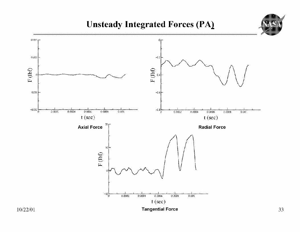
Unsteady Integrated Forces (PA_ @
O_O,)Z
0._i
-0_01
-0_
-_.6
-0.,:0,_ O_ 0.00D_ 0,_8 0.001
t (sec)
20Axial Force
.........._............._.............._............2[ ............._.............1............._..............l_............._...........21............._...............0 0:0C02 O,COC_ 0 :OZ_ 0.¢038 O,O0:I
t (see)
Radial Force
0 .k._2. 0 .¢N304 0. OOL',6 0 .COD8 0 .CO1
t (sec)
10/22/01 Tangential Force 33

Conclusions
Full admission simulation performed for the Simplex turbine
- models one nozzle and 12 rotors
- Mach number of flow exiting nozzle low
- Mach number at rotor exit too high
- unsteadiness predominantly a nozzle-passing and twice nozzle-
passing frequency
Partial admission simulation underway for Simplex turbine
- models all nozzles and rotors
- design Mach number obtained at nozzle exit
- design Mach number obtained at rotor exit
- unsteadiness at nozzle-passing and lower frequencies
10/22/01 34