
Comparison of Fixed and Adaptive Mesh Results for HiLiftPW-3 · Copyright © 2016 Boeing. All...
29
Engineering, Operations & Technology Copyright © 2016 Boeing. All rights reserved. Boeing Research & Technology Comparison of Fixed and Adaptive Mesh Results for HiLiftPW-3 Todd Michal, Dmitry Kamenetskiy, Josh Krakos Boeing Research and Technology PID 007 3 rd High Lift Prediction Workshop Denver, CO June 3-4, 2017
Transcript of Comparison of Fixed and Adaptive Mesh Results for HiLiftPW-3 · Copyright © 2016 Boeing. All...

Engineering, Operations & Technology
Copyright © 2016 Boeing. All rights reserved.
Boeing Research & Technology
Comparison of Fixed and Adaptive Mesh Results for HiLiftPW-3
Todd Michal, Dmitry Kamenetskiy, Josh Krakos
Boeing Research and Technology
PID 007
3rd High Lift Prediction Workshop
Denver, CO June 3-4, 2017

Copyright © 2016 Boeing. All rights reserved.
Boeing Research & Technology | Aerosciences
Summary of cases completed: GGNS, SA-QCR
Case (HL-CRM) Alpha=8,
Fully turb, grid study
Alpha=16,
Fully turb, grid study
Other
1a (full gap) yes yes
1b (full gap w adaption) yes yes
1c (partial seal) yes yes
1d (partial seal w adaption) yes yes
2HiLiftPW-3, Denver CO, June 2017
Case (JSM) Polar, Fully
turb
Polar,
specified
transition
Polar, w
transition
prediction
Other
2a (no nacelle) yes no no
2b (no nacelle w
adaption)yes no no
2c (with nacelle) yes no no
2d (with nacelle w
adaption)yes no no
Case (DSMA661) 2D Verification
study
Other
3 yes
Other adapted
Copyright © 2016 Boeing. All rights reserved.
Boeing Research & Technology | Aerosciences
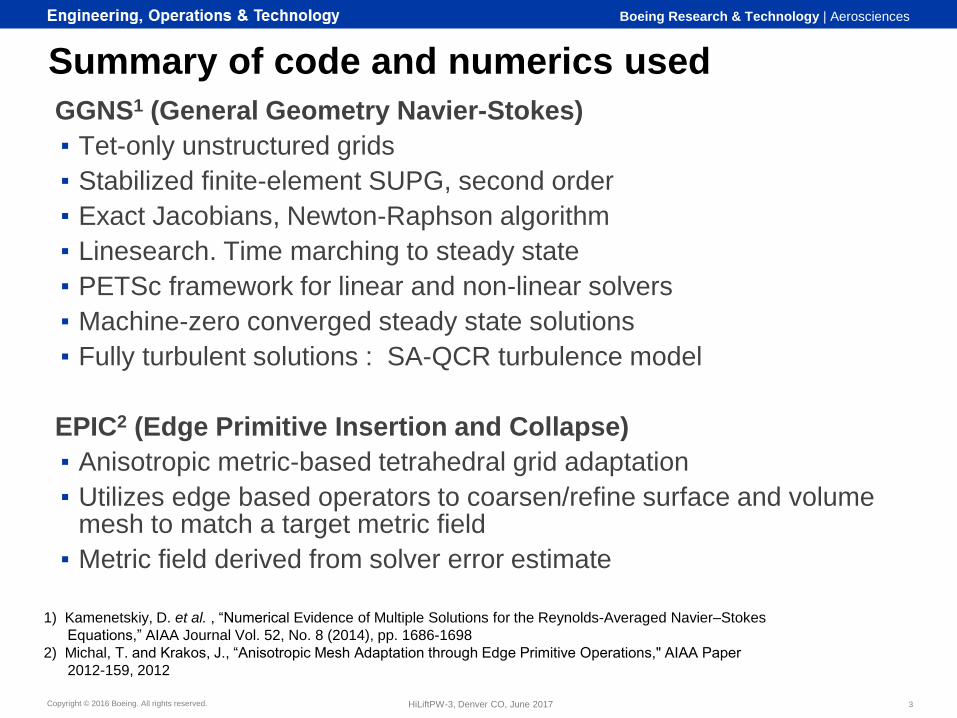
Summary of code and numerics used
GGNS1 (General Geometry Navier-Stokes)
▪ Tet-only unstructured grids
▪ Stabilized finite-element SUPG, second order
▪ Exact Jacobians, Newton-Raphson algorithm
▪ Linesearch. Time marching to steady state
▪ PETSc framework for linear and non-linear solvers
▪ Machine-zero converged steady state solutions
▪ Fully turbulent solutions : SA-QCR turbulence model
EPIC2 (Edge Primitive Insertion and Collapse)
▪ Anisotropic metric-based tetrahedral grid adaptation
▪ Utilizes edge based operators to coarsen/refine surface and volume mesh to match a target metric field
▪ Metric field derived from solver error estimate
3HiLiftPW-3, Denver CO, June 2017
1) Kamenetskiy, D. et al. , “Numerical Evidence of Multiple Solutions for the Reynolds-Averaged Navier–Stokes
Equations,” AIAA Journal Vol. 52, No. 8 (2014), pp. 1686-1698
2) Michal, T. and Krakos, J., “Anisotropic Mesh Adaptation through Edge Primitive Operations," AIAA Paper
2012-159, 2012
Copyright © 2016 Boeing. All rights reserved.
Boeing Research & Technology | Aerosciences
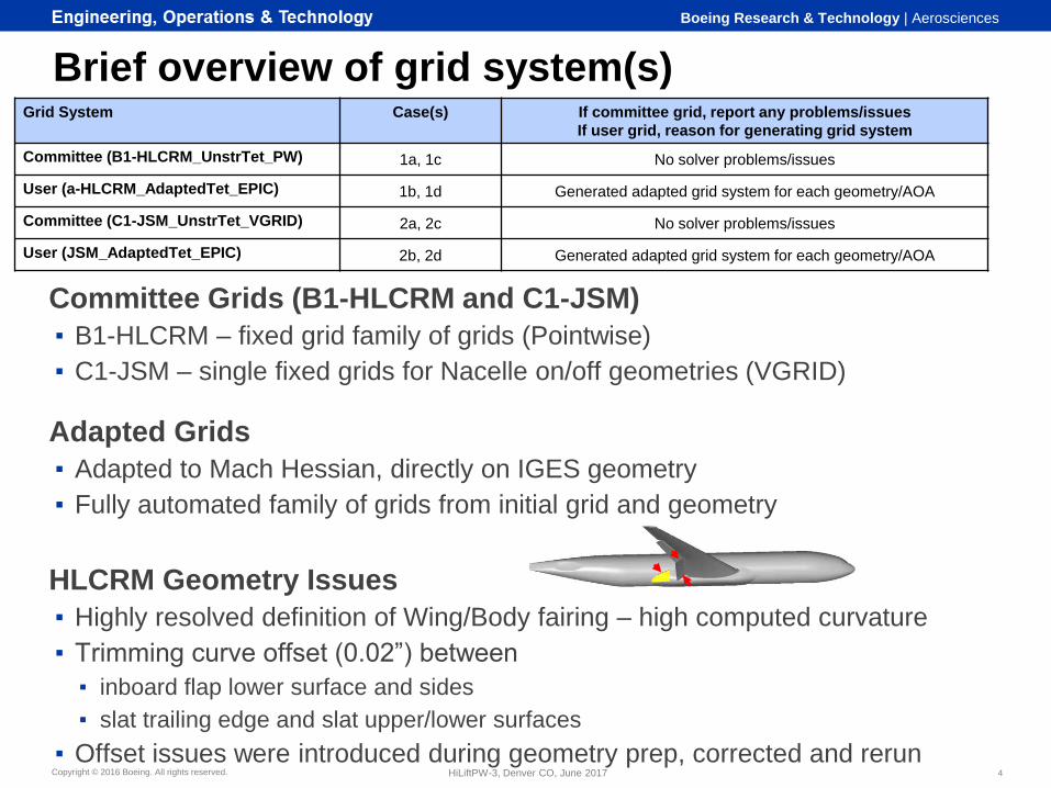
Brief overview of grid system(s)
Committee Grids (B1-HLCRM and C1-JSM)
▪ B1-HLCRM – fixed grid family of grids (Pointwise)
▪ C1-JSM – single fixed grids for Nacelle on/off geometries (VGRID)
Adapted Grids
▪ Adapted to Mach Hessian, directly on IGES geometry
▪ Fully automated family of grids from initial grid and geometry
HLCRM Geometry Issues
▪ Highly resolved definition of Wing/Body fairing – high computed curvature
▪ Trimming curve offset (0.02”) between
▪ inboard flap lower surface and sides
▪ slat trailing edge and slat upper/lower surfaces
▪ Offset issues were introduced during geometry prep, corrected and rerun4HiLiftPW-3, Denver CO, June 2017
Grid System Case(s) If committee grid, report any problems/issues
If user grid, reason for generating grid system
Committee (B1-HLCRM_UnstrTet_PW) 1a, 1c No solver problems/issues
User (a-HLCRM_AdaptedTet_EPIC) 1b, 1d Generated adapted grid system for each geometry/AOA
Committee (C1-JSM_UnstrTet_VGRID) 2a, 2c No solver problems/issues
User (JSM_AdaptedTet_EPIC) 2b, 2d Generated adapted grid system for each geometry/AOA

Copyright © 2016 Boeing. All rights reserved.
Boeing Research & Technology | Aerosciences
Author, 6/7/2017, Filename.ppt | 5HiLiftPW-3, Denver CO, June 2017
Example Adaptation SequenceJSM case2d, Mach 0.172, Re=1.93M, a=14.54o Grid Level 0
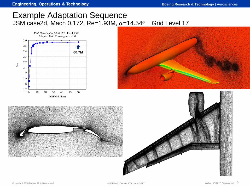
• Start with coarse initial grid
• Generate solution and error estimate
• Derive anisotropic sizing field that
distributes mesh DOF to equilibrate
error over domain
Initial Mesh Nodes=678K
Copyright © 2016 Boeing. All rights reserved.
Boeing Research & Technology | Aerosciences
Author, 6/7/2017, Filename.ppt | 6HiLiftPW-3, Denver CO, June 2017
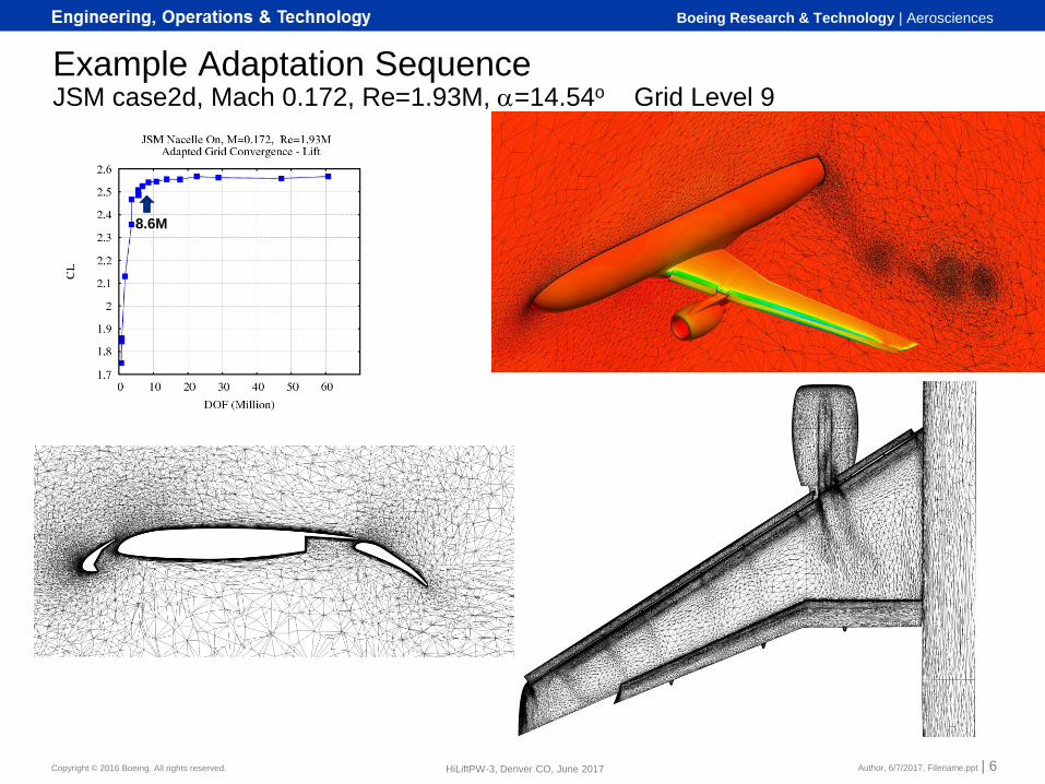
Example Adaptation SequenceJSM case2d, Mach 0.172, Re=1.93M, a=14.54o Grid Level 9
8.6M

Copyright © 2016 Boeing. All rights reserved.
Boeing Research & Technology | Aerosciences
Author, 6/7/2017, Filename.ppt | 7HiLiftPW-3, Denver CO, June 2017
Example Adaptation SequenceJSM case2d, Mach 0.172, Re=1.93M, a=14.54o Grid Level 12
17.7M
Copyright © 2016 Boeing. All rights reserved.
Boeing Research & Technology | Aerosciences
Author, 6/7/2017, Filename.ppt | 8HiLiftPW-3, Denver CO, June 2017
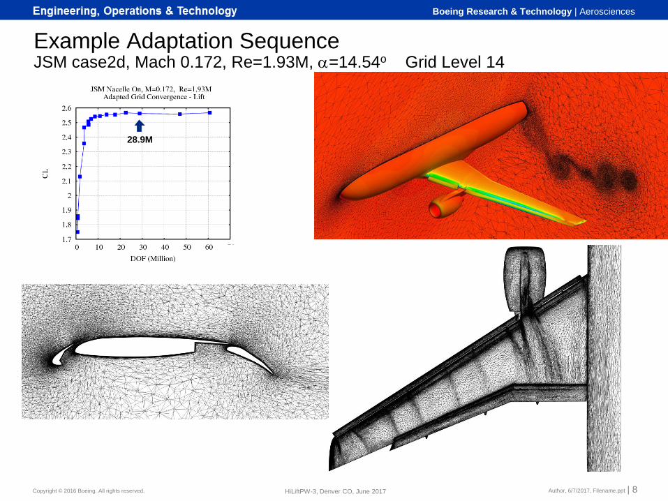
Example Adaptation SequenceJSM case2d, Mach 0.172, Re=1.93M, a=14.54o Grid Level 14
28.9M
Copyright © 2016 Boeing. All rights reserved.
Boeing Research & Technology | Aerosciences
Author, 6/7/2017, Filename.ppt | 9HiLiftPW-3, Denver CO, June 2017
Example Adaptation SequenceJSM case2d, Mach 0.172, Re=1.93M, a=14.54o Grid Level 17
60.7M

Copyright © 2016 Boeing. All rights reserved.
Boeing Research & Technology | Aerosciences
Adaptive Grid Generated at Each Solution PointJSM Adapted Surface Grids for Angle of Attack Sweep
Author, 6/7/2017, Filename.ppt | 10HiLiftPW-3, Denver CO, June 2017
a=4.36 a=10.47
a=14.54 a=18.58
a=20.59 a=21.57
Copyright © 2016 Boeing. All rights reserved.
Boeing Research & Technology | Aerosciences
Author, 6/7/2017, Filename.ppt | 11HiLiftPW-3, Denver CO, June 2017
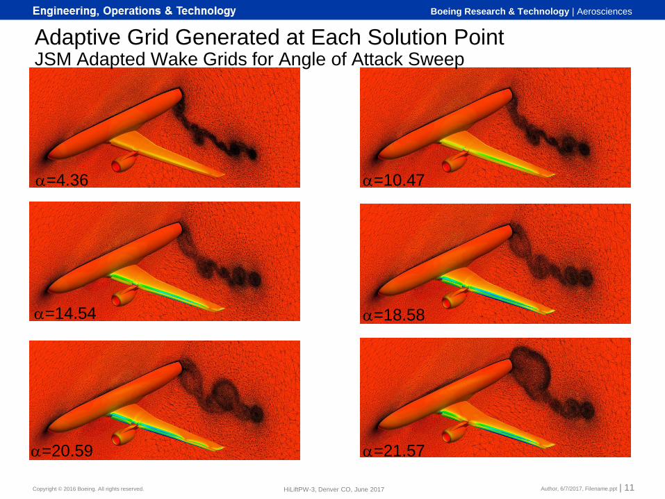
a=4.36 a=10.47
a=14.54 a=18.58
a=20.59 a=21.57
Adaptive Grid Generated at Each Solution PointJSM Adapted Wake Grids for Angle of Attack Sweep

Copyright © 2016 Boeing. All rights reserved.
Boeing Research & Technology | Aerosciences
HL-CRM Cases (Gapped and Partially Sealed)
12HiLiftPW-3, Denver CO, June 2017
Objective: Compare adapted and fixed grid solutions
Fixed grid family: B1-HLCRM_UnstrTet_PW
Adapted grid family: a-HLCRM_AdaptedTet_EPIC
Sample Solution Convergence
Fixed Grid Adapted Grid
CL - Coarse Grid
CL - Medium Grid
CL - Fine Grid
Residual – Coarse Grid
Residual – Medium Grid
Residual – Fine Grid
Machine zero residual convergence achieved for nearly all solutions
Adapted grid solutions converge in fewer iterations (better initial guess)

Copyright © 2016 Boeing. All rights reserved.
Boeing Research & Technology | Aerosciences
HL-CRM - Fixed and Adapted Grid Convergence
Author, 6/7/2017, Filename.ppt | 13HiLiftPW-3, Denver CO, June 2017
a-HLCRM_Adapted Grid B1-HLCRM_PW Fixed Grid
Red Gapped Geometry Green Partial Seal Geometry
Line/Symbol (Grid Type) :
Color (Geometry Model):
Adapted solutions converge to near constant lift (~ 10M DOF)Slight increase in CL with grid resolution continues
Consistent seal-gap increment with increasing grid resolution
Insufficient data to evaluate fixed grid convergence
Non-asymptotic convergence for the gapped geometry
One data point for increment
6M 10M 30M 90M 3M
Copyright © 2016 Boeing. All rights reserved.
Boeing Research & Technology | Aerosciences
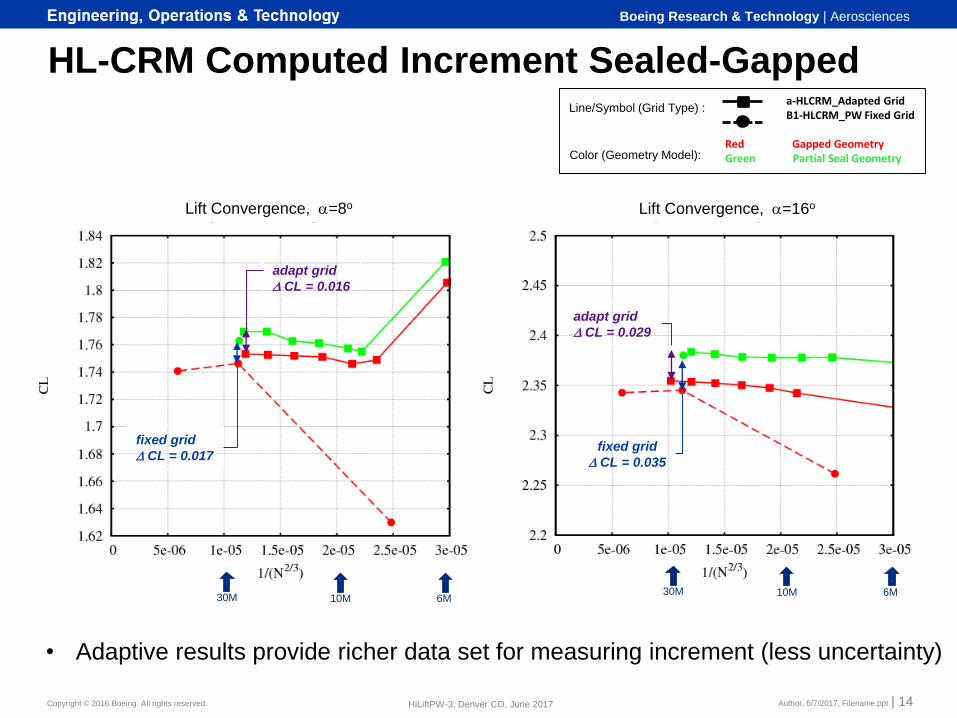
HL-CRM Computed Increment Sealed-Gapped
Author, 6/7/2017, Filename.ppt | 14HiLiftPW-3, Denver CO, June 2017
Lift Convergence, a=8o Lift Convergence, a=16o
6M 10M 30M 6M 10M 30M
a-HLCRM_Adapted Grid B1-HLCRM_PW Fixed Grid
Red Gapped Geometry Green Partial Seal Geometry
Line/Symbol (Grid Type) :
Color (Geometry Model):
fixed grid
D CL = 0.017
adapt grid
D CL = 0.016
adapt grid
D CL = 0.029
fixed grid
D CL = 0.035
• Adaptive results provide richer data set for measuring increment (less uncertainty)

Copyright © 2016 Boeing. All rights reserved.
Boeing Research & Technology | Aerosciences
Solution Comparison in Flap Gaps, HLCRM AoA=16 degrees
Author, 6/7/2017, Filename.ppt | 15HiLiftPW-3, Denver CO, June 2017
Fully Gapped - Fixed Fine Grid
Fully Gapped - Adapt Fine Grid
Partially Sealed - Fixed Fine Grid
Partially Sealed - Adapt Fine Grid
flap/body gap flap/flap gap flap/body gap flap/flap gap
Fixed mesh under
resolved along flap
edges
Different skin friction/ flow
separation patterns between
fixed/adapted solutions
Copyright © 2016 Boeing. All rights reserved.
Boeing Research & Technology | Aerosciences
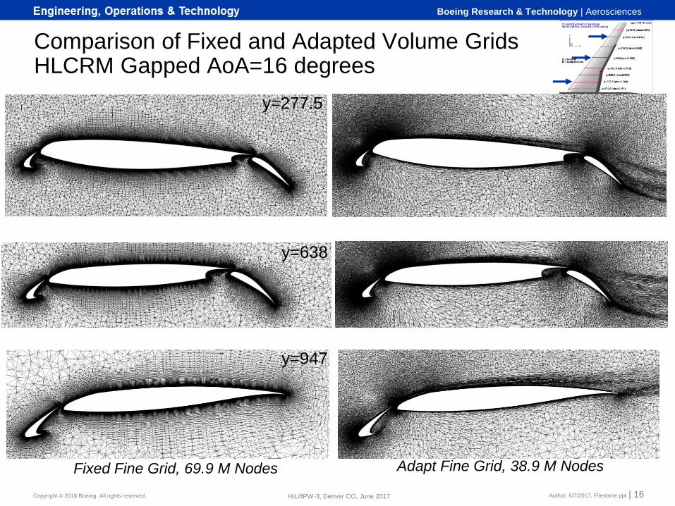
Comparison of Fixed and Adapted Volume GridsHLCRM Gapped AoA=16 degrees
Author, 6/7/2017, Filename.ppt | 16HiLiftPW-3, Denver CO, June 2017
Offbody Grid
Comparison
y=277.5
y=638
y=947
Fixed Fine Grid, 69.9 M Nodes Adapt Fine Grid, 38.9 M Nodes
Copyright © 2016 Boeing. All rights reserved.
Boeing Research & Technology | Aerosciences
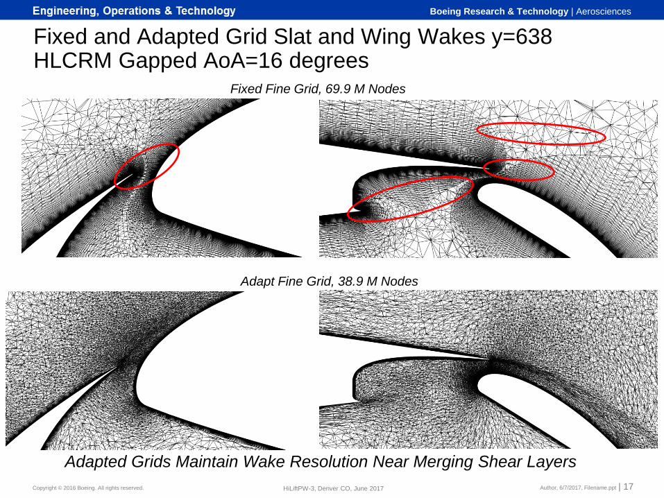
Fixed and Adapted Grid Slat and Wing Wakes y=638HLCRM Gapped AoA=16 degrees
Author, 6/7/2017, Filename.ppt | 17HiLiftPW-3, Denver CO, June 2017
Adapted Grids Maintain Wake Resolution Near Merging Shear Layers
Fixed Fine Grid, 69.9 M Nodes
Adapt Fine Grid, 38.9 M Nodes

Copyright © 2016 Boeing. All rights reserved.
Boeing Research & Technology | Aerosciences
Fixed and Adapted Grid Velocity Profile x=1615, y=638HLCRM Gapped AoA=16 degrees
Author, 6/7/2017, Filename.ppt | 18HiLiftPW-3, Denver CO, June 2017
Fixed Fine Grid, 69.9 M Nodes
Adapt Fine Grid, 38.9 M Nodes

Copyright © 2016 Boeing. All rights reserved.
Boeing Research & Technology | Aerosciences
JAXA JSM Cases with and without Nacelle
Author, 6/7/2017, Filename.ppt | 19HiLiftPW-3, Denver CO, June 2017
Fixed Grid Adapted Grid
CL – a=10.47
CL - a=18.58
CL - a=20.59
Residual – a=10.47
Residual – a=18.58
Residual – a=20.59
Objective: Compare adapted and fixed grid solutions
Fixed grid family: C1-JSM_UnstrTet_VGRID
Adapted grid family: JSM_AdaptedTet_EPIC
Sample Solution Convergence (JSM with Nacelle)
Almost all solutions converge to machine zero residuals at pre-stall angle of attack
Post stall solutions do not converge as well
Adapted grid solutions converge in fewer iterations compared to fixed grid

Copyright © 2016 Boeing. All rights reserved.
Boeing Research & Technology | Aerosciences
JAXA JSM – Adapted Grid Convergence
Author, 6/7/2017, Filename.ppt | 20HiLiftPW-3, Denver CO, June 2017
JSM Nacelle On
Adapted Grid Convergence - Lift
Post CLmax
Rapid convergence to ~ 10M DOF followed by slow convergence to final lift
Pre stall solutions convergence to near constant lift
Post stall solutions not as close to grid converged
Multiple solution branches complicate adaptive process
open symbols indicate flow solutions
that failed to converge to machine
zero residual

Copyright © 2016 Boeing. All rights reserved.
Boeing Research & Technology | Aerosciences
JSM Nacelle On/Off - Forces and Pitching Moment
21HiLiftPW-3, Denver CO, June 2017
Lift Curve Drag Polar Pitching Moment
Fixed Grid
Adapted Grid
Fixed Grid
Adapted Grid
Fixed Grid
Adapted Grid
Little difference between
fixed grid nacelle on/off
solutions
Good agreement with
test data for nacelle
on/off pre-stall solutions
Fixed and adapted
solutions over predict
drag
Nacelle off solutions were
adapted to coarser grid
resolution (~ 20M DOF)
Excellent agreement
with test data for nacelle
on pre-stall solutions

Copyright © 2016 Boeing. All rights reserved.
Boeing Research & Technology | Aerosciences
JSM Oil Flows AoA=4.36o
22HiLiftPW-3, Denver CO, June 2017
Test Fix GridAdapted Grid

Copyright © 2016 Boeing. All rights reserved.
Boeing Research & Technology | Aerosciences
JSM Oil Flows AoA=10.47o
23HiLiftPW-3, Denver CO, June 2017
Test Fix GridAdapted Grid

Copyright © 2016 Boeing. All rights reserved.
Boeing Research & Technology | Aerosciences
JSM Oil Flows AoA=18.59o
24HiLiftPW-3, Denver CO, June 2017
Test Fix GridAdapted Grid
Copyright © 2016 Boeing. All rights reserved.
Boeing Research & Technology | Aerosciences
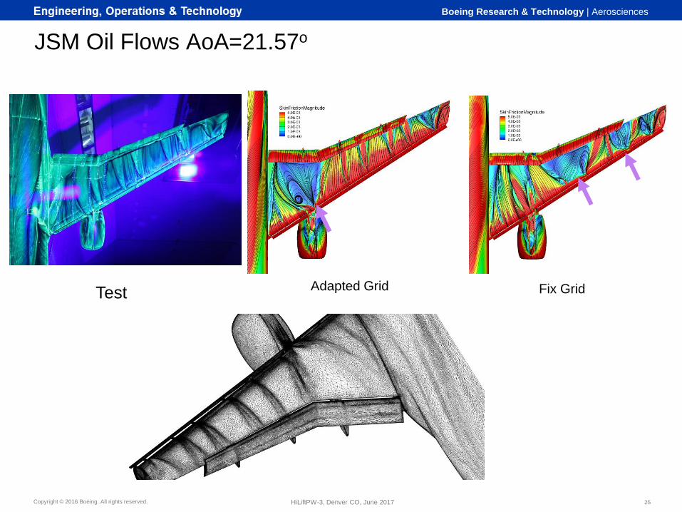
JSM Oil Flows AoA=21.57o
25HiLiftPW-3, Denver CO, June 2017
Test Fix GridAdapted Grid

Copyright © 2016 Boeing. All rights reserved.
Boeing Research & Technology | Aerosciences
JSM with Nacelle AoA=14.54
Author, 6/7/2017, Filename.ppt | 26HiLiftPW-3, Denver CO, June 2017
Adapt C1-JSM VGRID
Different
fixed/adapted
pressures in slat
attach bracket wakes
Larger separation on
outboard wing
Copyright © 2016 Boeing. All rights reserved.
Boeing Research & Technology | Aerosciences
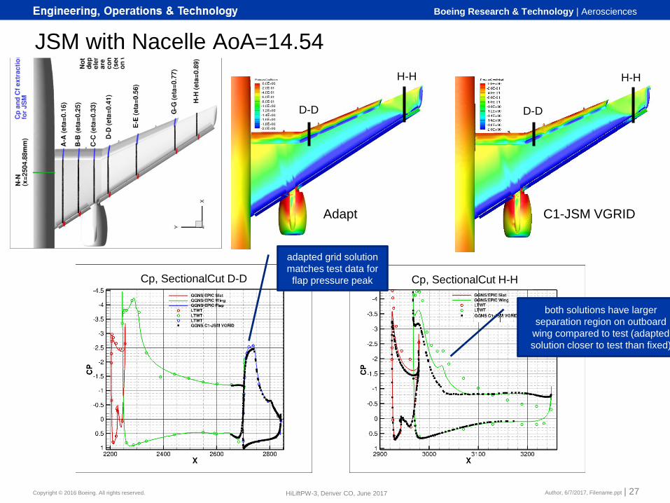
JSM with Nacelle AoA=14.54
Author, 6/7/2017, Filename.ppt | 27HiLiftPW-3, Denver CO, June 2017
Adapt C1-JSM VGRID
H-H
D-D
H-H
D-D
Cp, SectionalCut D-D Cp, SectionalCut H-H
adapted grid solution
matches test data for
flap pressure peak
both solutions have larger
separation region on outboard
wing compared to test (adapted
solution closer to test than fixed)

Copyright © 2016 Boeing. All rights reserved.
Boeing Research & Technology | Aerosciences
Summary Adaptive Mesh Solutions
Machine zero solution residual convergence obtained for most pre-stall solutions
Results approach constant lift with grid size for all cases
HLCRM Fixed/Adapted Grid Comparison
Adapted grids better at resolving merging shear layers and details of flap gaps
Better grid convergence achieved for adapted grid results even at coarse grid sizes
Adaptive approach provided richer data set for measuring gap/seal increment
JSM Fixed/Adapted Grid Comparison
Adapted results better at predicting slat attach wake impact on flap surface pressure and outboard wing separation
Adapted results predict nacelle on/off CL increment accurately compared to fixed grid
Adaptation did not improve CLmax prediction, both approaches predicted angle of attack at CLmax ~ 1o early with nacelle and > 2o early without nacelle
Adaptive Meshing Provided Several Advantages
Automatic generation of consistent mesh family saved weeks of labor by an expert user compared to fixed grid approach
No a priori solution knowledge required
Reduced solution uncertainty due to mesh
Author, 6/7/2017, Filename.ppt | 28GMGW-1, Denver CO, June 2017

Copyright © 2016 Boeing. All rights reserved.
Boeing Research & Technology | Aerosciences
Boeing DPW6, 7/10/2016 | 29