Recent Advancements in the Development of Inflatable Multi ...
56
Int. J. Elec&Electr.Eng&Telecoms. 2014 Mopidevi Raghava and M Gopi Chand Naik, 2014
COMPARATIVE STUDY OF RECENTADVANCEMENTS IN REGENERATIVE DRIVES IN
ELEVATOR SYSTEMS
Mopidevi Raghava1* and M Gopi Chand Naik1
*Corresponding Author: Mopidevi Raghava, [email protected]
Regenerative motor-drive systems are nowadays widely applied in numerous industrialapplications. This paper is centered on comparing the application of the two well-known andrecently used types of drives for AC gearless elevators. This paper presents a comparativeevaluation of the regenerative Permanent Magnet Synchronous Motor (PMSM) and AC VariableVoltage Variable Frequency (VVVF) drives. The study includes a detailed analysis of energyconsumption, line running, accelerating and peak current and peak demand for each elevatorcontrol system. This paper shows the simulated results of output power, hoisting power,regenerative power, power savings which are compared for these drives along with theimplementation of Automatic Rescue Device (ARD) for emergency operation using a batterywith ultra capacitor combination which is charged by the regenerated power using converters.
Keywords: Elevator, Electric drive, Regenerative drives PMSM, AC VVVF, ARD, Lithium ionbattery ultra Capacitor, Inverter, Peak demand
INTRODUCTIONPower Quality is an increasing concern forutilities and their commercial and industrialelectrical customers. In recent years, theproliferation of higher electronic loads andcontrols have taken a sensitive place toelectrical grid disturbances, such as voltagesags, dips, outages, over voltage, harmonicsdistortion and so on. The growing demand oflow CO2 emissions, leads to heavy market
ISSN 2319 – 2518 www.ijeetc.comVol. 3, No. 2, April 2014
© 2014 IJEETC. All Rights Reserved
Int. J. Elec&Electr.Eng&Telecoms. 2014
1 Department of Electrical Engineering, Andhra University College of Engineering (A), Visakhapatnam, Andhra Pradesh, India.
penetration of generating energy capable toassure low exhaust emission.
The DC motor is widely used for elevatormotion control with Ward Leonard systemusing a motor generator (MG) set andsubsequently, using thyristor drives in the1980s and 1990s. Gate Turn Off devices(GTOs) controlled the DC motors for elevatorapplication to obtain better voltage and powerfactor control. The DC motor with its brushes
Research Paper
57
Int. J. Elec&Electr.Eng&Telecoms. 2014 Mopidevi Raghava and M Gopi Chand Naik, 2014
requires frequent maintenance therefore, thenext logical choice for elevators was to employAC motor and reduce maintenance cost. AGTO current source inverter and AC inductionmotor were used for elevator applications.Here the GTO switching frequency was nearly4 kHz and special GTO gating scheme wasused to suppress the voltage spikes. Atransistor based current source PWM invertersystem with sinusoidal input and output wasapplied to high-speed elevators in the late1980s. The switching frequency employed was2.7 kHz and the individual input currentharmonics were reported to be less than 5%.Over the last decade, Variable VoltageVariable Frequency (VVVF) vector controlledAC drive using Insulated Gate BipolarTransistor (IGBT) switching devices and ACinduction motor has been the most popularmotion control system for elevators.
The VVVF AC system has replaced theWard Leonard MG, silicon controlled rectifieror SCR, GTO and transistor inverter (AC)based systems for majority of elevators. Thevector-controlled drives provide a DC servolike performance and the AC induction motordoes not need frequent maintenance.
A current controlled AC inverter with a highswitching frequency (6-12 kHz) provides agood control of torque down to zero speed withlow torque ripple. There is a substantial amountof overhauling energy when an elevator travelsin a high-rise building with excess energy inthe system. A line regenerative drive, therefore,offers substantial energy savings for high-speed elevators. The energy saving is not soclear however, for gearless elevators travellingat the lower end of the gearless speed range,for example at 2.5 m/s. However another motor
drive is rapidly gaining popularity in elevatormarket, i.e., the PMSM drives. Permanent-Magnet Synchronous Motors haveperformance advantages over DC excited-synchronous motors and are becoming morecommon in fractional horsepower applicationsbecause they are smaller, lighter, moreefficient and reliable. So in this discussion, wecompare both PMSM drive and AC VVVFdrive for a lift car with a capacity of 8passengers travelling at 1m/s speed for 3floors.
REGENERATIVE DRIVES INELEVATOR APPLICATIONSWhen an electric motor is driven by a VariableFrequency Drive (VFD), electric powerdelivered to the motor is regenerated while themotor decelerates by applying negative torqueto the motor shaft. Usually energy storagecapacity inside the VFD is very limited soregenerative energy should be returned to thegrid or quickly dissipated by a braking resistor.Otherwise, the dc bus will be overcharged andan over-voltage fault can occur. Dynamicbraking resistors have been widely used toconvert regenerated energy into heat lossbecause of simplicity and low installation cost.But a regenerative power unit provides asignificant energy cost saving opportunity,especially in applications that require frequentrun and stop, deceleration with high inertiaload, and overhauling torque. Suchapplications include spindle drives, decantercentrifuges, hoists, cranes, elevators, andtorque dynamometer test rigs.
Motor SelectionMotor selection is important in an elevator drivesystem, as mentioned earlier the DC motor-
58
Int. J. Elec&Electr.Eng&Telecoms. 2014 Mopidevi Raghava and M Gopi Chand Naik, 2014
generator sets are being replaced by variousmotors, of these most popular are thePermanent Magnet Synchronous Motors andAC VVVF drives.
• Variable Voltage Variable Frequency(VVVF) drives eliminate the need for a DChoist motor and replace it with an AC motor.VVVF provides many of the sameadvantageous characteristics of the DCmotor, such as smooth acceleration anddeceleration and excellent speed controlwithout the issues related to usability ofpower.
• Permanent-Magnet Motors haveperformance advantages over DC excited-synchronous motors and are becomingmore common in fractional horsepowerapplications because they are smaller,lighter, more efficient and reliable. Largeindustrial motors originally used wound fieldor rotor magnets. Permanent-magnets havetraditionally been used only on smallermotors because of the difficulty in finding amaterial capable of retaining a high-strengthfield. Recent improvements in materialtechnologies have made it possible tocreate high-intensity permanent-magnets,allowing the development of compact, high-power motors without the extra real estateof field coils and excitation means.
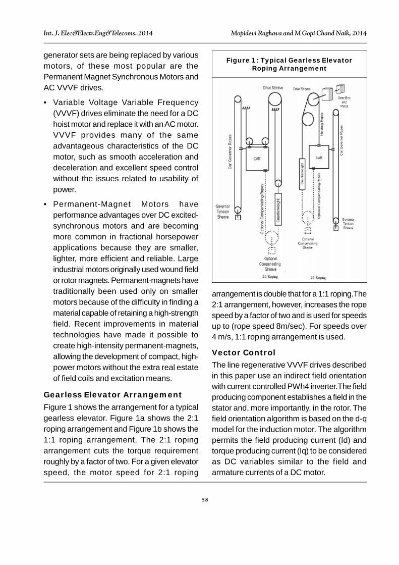
Gearless Elevator ArrangementFigure 1 shows the arrangement for a typicalgearless elevator. Figure 1a shows the 2:1roping arrangement and Figure 1b shows the1:1 roping arrangement, The 2:1 ropingarrangement cuts the torque requirementroughly by a factor of two. For a given elevatorspeed, the motor speed for 2:1 roping
arrangement is double that for a 1:1 roping.The2:1 arrangement, however, increases the ropespeed by a factor of two and is used for speedsup to (rope speed 8m/sec). For speeds over4 m/s, 1:1 roping arrangement is used.
Vector ControlThe line regenerative VVVF drives describedin this paper use an indirect field orientationwith current controlled PWh4 inverter.The fieldproducing component establishes a field in thestator and, more importantly, in the rotor. Thefield orientation algorithm is based on the d-qmodel for the induction motor. The algorithmpermits the field producing current (Id) andtorque producing current (Iq) to be consideredas DC variables similar to the field andarmature currents of a DC motor.
Figure 1: Typical Gearless ElevatorRoping Arrangement
59
Int. J. Elec&Electr.Eng&Telecoms. 2014 Mopidevi Raghava and M Gopi Chand Naik, 2014
Regenerative Energy RetrievalThe Regenerated energy from the motors isretrieved by the help of the regenerativeconverter, a cost-effective solution that canreplace the dynamic braking transistor andresistor network. It absorbs excessregenerative energy from the VFD and returnsit to the ac power source. During motoring, theVFD delivers power without the regenerativeconverter in the main power flow. So there isno conduction loss in the regenerativeconverter during motoring. The regenerativeconverter is activated when regenerativeenergy charges dc link capacitors of the VFD.The regenerative converter returns storedenergy in the dc capacitors to the grid. Butinstead of using a separate converter forregenerated energy, a single converter can beused for both motoring as well as regenerativeenergy. Such types of converters are:
• Sinusoidal PWM converter
• Matrix Converter
• Current Source Inverters
Elevator Position ControlThe elevator control is performed by an Intel80186 microprocessor. A second encodermounted on the over speed governor detectsthe position of the elevator in the hoist way.Optical switches at each floor define the floorposition. The elevator controller generates theprecise S-curve for single or multi floor runsbased on hall and car calls and passes thespeed command information to the DSP tocontrol the elevator speed. A load weighingsystem on the elevator senses the precise loadon the elevator in pounds and passes thatinformation to the elevator controller. The80186 controller has job specific data such as
speed, capacity, number of floors and thepercent counterweight. The 80186 processorevaluates the unbalance on the car after itreceives the load information before the startof each run and calculates the precise amountof pre torque needed for smooth operation ofelevator.
ENERGY CONSUMPTIONGearless Elevator EnergyConsumptionThe elevator energy consumption depends ona number of factors such as the type of driveused, capacity of the elevator, speed of theelevator, traffic pattern in the building, full loadmass of the system, type of gearless machineused, type of roping, etc. A good analytical toolto evaluate the energy consumption istherefore of great interest. An analyticalapproach to evaluating the average energyconsumption is presented in this section.
Unit of EnergyThe unit of energy universally used is kilowatt-hour, kWh. It is defined as the energyconsumed by an appliance or system with apower of one kilowatt or 1000 watt for a periodof 1 hour.
Elevator Flight TimesThe elevator flight time for a given number of floorsdepends on the rated speed of the elevator,acceleration and deceleration rates, jerk ratesand the door open and close times. Themethodology presented, however, is applicableto a different acceleration rate with a smallvariation in flight times. The average energyconsumption number using different accelerateor deceleration rate is not affected much sincean elevator travelling at lower accelerate or
60
Int. J. Elec&Electr.Eng&Telecoms. 2014 Mopidevi Raghava and M Gopi Chand Naik, 2014
deceleration rate generally spends more time toget to a given floor and thus makes fewer totalnumber of trips overall per day.
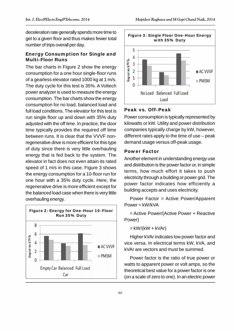
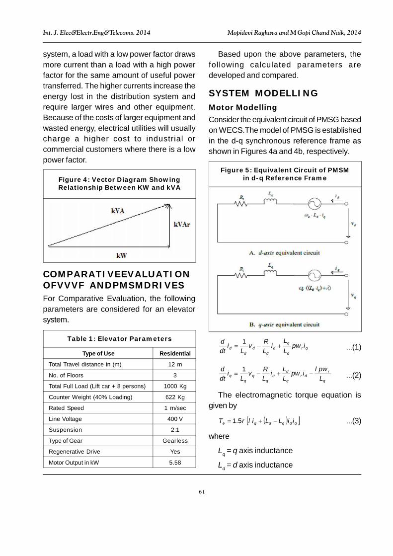
Energy Consumption for Single andMulti-Floor RunsThe bar charts in Figure 2 show the energyconsumption for a one hour single-floor runsof a gearless elevator rated 1000 kg at 1 m/s.The duty cycle for this test is 35%. A Voltechpower analyzer is used to measure the energyconsumption. The bar charts show the energyconsumption for no load, balanced load andfull load conditions. The elevator for this test isrun single floor up and down with 35% dutyadjusted with the off time. In practice, the doortime typically provides the required off timebetween runs. It is clear that the VVVF non-regenerative drive is more efficient for this typeof duty since there is very little overhaulingenergy that is fed back to the system. Theelevator in fact does not even attain its ratedspeed of 1 m/s in this case. Figure 3 showsthe energy consumption for a 10-floor run forone hour with a 35% duty cycle. Here, theregenerative drive is more efficient except forthe balanced load case when there is very littleoverhauling energy.
Peak vs. Off-PeakPower consumption is typically represented bykilowatts or kW. Utility and power distributioncompanies typically charge by kW, however,different rates apply to the time of use – peakdemand usage versus off-peak usage.
Power FactorAnother element in understanding energy useand distribution is the power factor or, in simpleterms, how much effort it takes to pushelectricity through a building or power grid. Thepower factor indicates how efficiently abuilding accepts and uses electricity.
Power Factor = Active Power/ApparentPower = kW/kVA
= Active Power/(Active Power + ReactivePower)
= kW/(kW + kVAr)
Higher kVAr indicates low power factor andvice versa. In electrical terms kW, kVA, andkVAr are vectors and must be summed.
Power factor is the ratio of true power orwatts to apparent power or volt amps, so thetheoretical best value for a power factor is one(on a scale of zero to one). In an electric power
Figure 2: Energy for One-Hour 10-FloorRun 35% Duty
Figure 3: Single Floor One-Hour Energywith 35% Duty
61
Int. J. Elec&Electr.Eng&Telecoms. 2014 Mopidevi Raghava and M Gopi Chand Naik, 2014
system, a load with a low power factor drawsmore current than a load with a high powerfactor for the same amount of useful powertransferred. The higher currents increase theenergy lost in the distribution system andrequire larger wires and other equipment.Because of the costs of larger equipment andwasted energy, electrical utilities will usuallycharge a higher cost to industrial orcommercial customers where there is a lowpower factor.
Based upon the above parameters, thefollowing calculated parameters aredeveloped and compared.
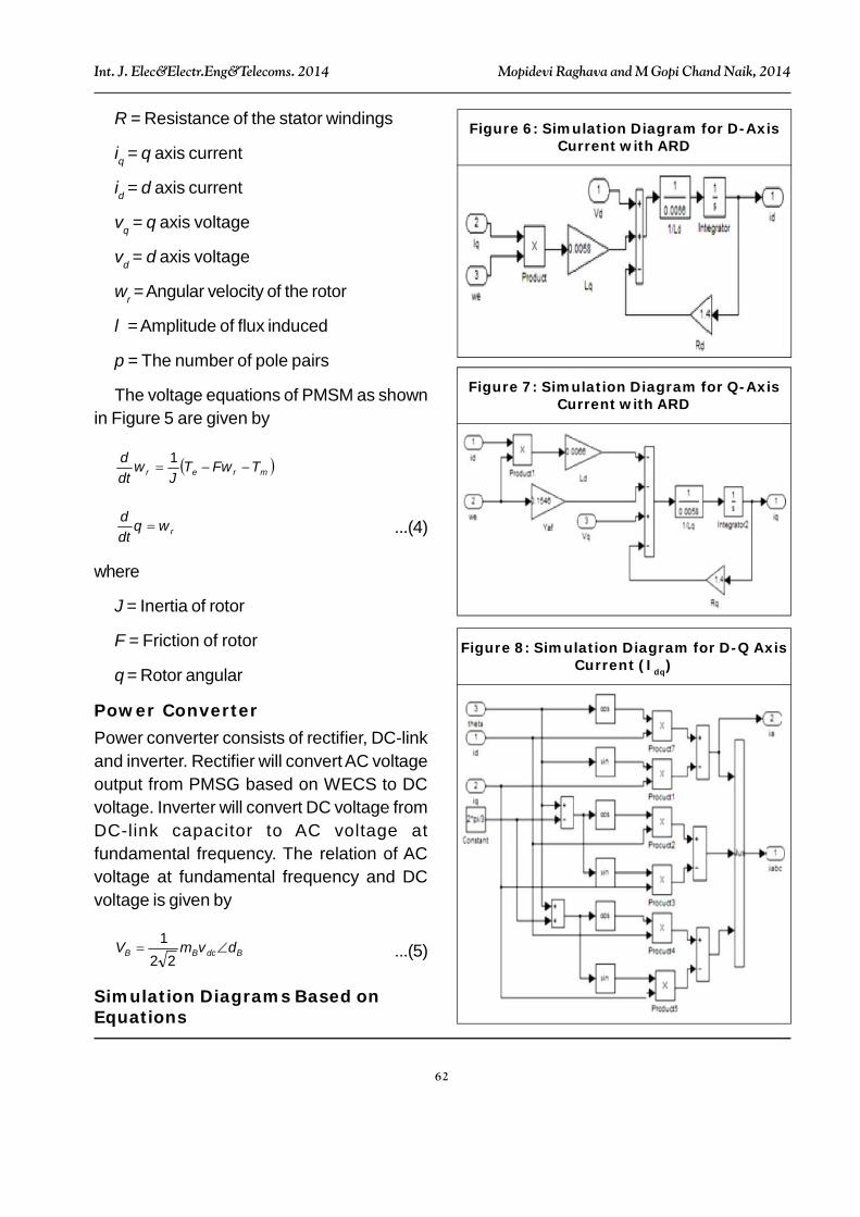
SYSTEM MODELLINGMotor ModellingConsider the equivalent circuit of PMSG basedon WECS.The model of PMSG is establishedin the d-q synchronous reference frame asshown in Figures 4a and 4b, respectively.
Figure 4: Vector Diagram ShowingRelationship Between KW and kVA
COMPARATIVEEVALUATIONOFVVVF ANDPMSMDRIVESFor Comparative Evaluation, the followingparameters are considered for an elevatorsystem.
Type of Use Residential
Total Travel distance in (m) 12 m
No. of Floors 3
Total Full Load (Lift car + 8 persons) 1000 Kg
Counter Weight (40% Loading) 622 Kg
Rated Speed 1 m/sec
Line Voltage 400 V
Suspension 2:1
Type of Gear Gearless
Regenerative Drive Yes
Motor Output in kW 5.58
Table 1: Elevator Parameters
Figure 5: Equivalent Circuit of PMSMin d-q Reference Frame
qrd
qd
dd
dd ipw
LL
iLRv
Li
dtd
1
...(1)
q
rdr
q
dq
qq L
pwipwLLi
LRv
Li
dtd
1
...(2)
The electromagnetic torque equation isgiven by
qdqdqe iiLLiT 5.1 ...(3)
where
Lq = q axis inductance
Ld = d axis inductance
62
Int. J. Elec&Electr.Eng&Telecoms. 2014 Mopidevi Raghava and M Gopi Chand Naik, 2014
R = Resistance of the stator windings
iq = q axis current
id = d axis current
vq = q axis voltage
vd = d axis voltage
wr = Angular velocity of the rotor
= Amplitude of flux induced
p = The number of pole pairs
The voltage equations of PMSM as shownin Figure 5 are given by
mrer TFwTJ
wdtd
1
rwdtd ...(4)
where
J = Inertia of rotor
F = Friction of rotor
= Rotor angular
Power ConverterPower converter consists of rectifier, DC-linkand inverter. Rectifier will convert AC voltageoutput from PMSG based on WECS to DCvoltage. Inverter will convert DC voltage fromDC-link capacitor to AC voltage atfundamental frequency. The relation of ACvoltage at fundamental frequency and DCvoltage is given by
BdcBB vmV 22
1...(5)
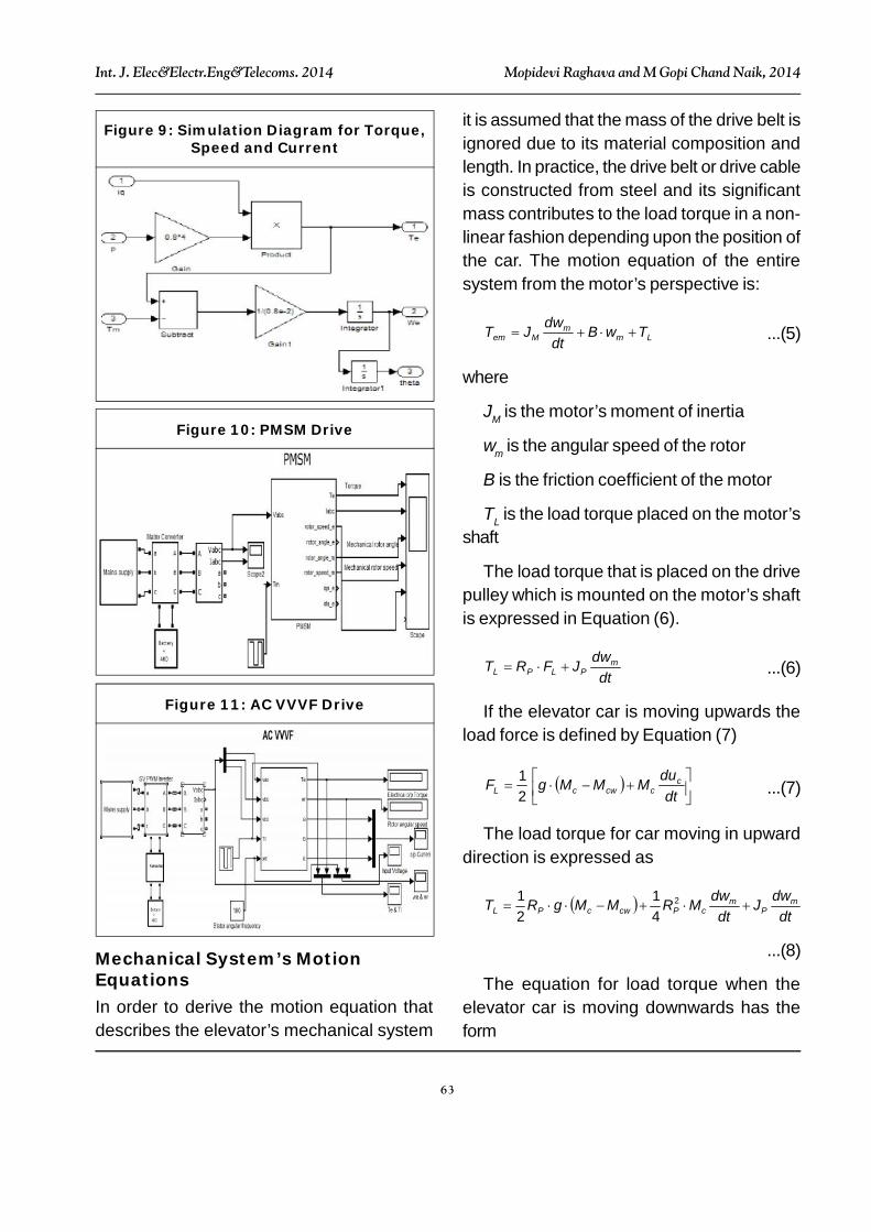
Simulation Diagrams Based onEquations
Figure 6: Simulation Diagram for D-AxisCurrent with ARD
Figure 7: Simulation Diagram for Q-AxisCurrent with ARD
Figure 8: Simulation Diagram for D-Q AxisCurrent (Idq)
63
Int. J. Elec&Electr.Eng&Telecoms. 2014 Mopidevi Raghava and M Gopi Chand Naik, 2014
it is assumed that the mass of the drive belt isignored due to its material composition andlength. In practice, the drive belt or drive cableis constructed from steel and its significantmass contributes to the load torque in a non-linear fashion depending upon the position ofthe car. The motion equation of the entiresystem from the motor’s perspective is:
Lmm
Mem TBdt
dJT
...(5)
where
JM is the motor’s moment of inertia
m is the angular speed of the rotor
B is the friction coefficient of the motor
TL is the load torque placed on the motor’sshaft
The load torque that is placed on the drivepulley which is mounted on the motor’s shaftis expressed in Equation (6).
dtdJFRT m
PLPL
...(6)
If the elevator car is moving upwards theload force is defined by Equation (7)
dtduMMMgF c
ccwcL 21
...(7)
The load torque for car moving in upwarddirection is expressed as
dt
dJdt
dMRMMgRT mP
mcPcwcPL
2
41
21
...(8)
The equation for load torque when theelevator car is moving downwards has theform
Figure 9: Simulation Diagram for Torque,Speed and Current
Figure 10: PMSM Drive
Figure 11: AC VVVF Drive
Mechanical System’s MotionEquationsIn order to derive the motion equation thatdescribes the elevator’s mechanical system
64
Int. J. Elec&Electr.Eng&Telecoms. 2014 Mopidevi Raghava and M Gopi Chand Naik, 2014
The Simulation results are as shown
dt
dJdt
dMRMMgRT mP
mcwPccwPL
2
41
21
...(9)
Substituting the load torque equation forwhen the elevator car is moving upwards(Equation 8) into the motor’s motion equation(Equation 9), the motion equation of the entiresystem is obtained as:
dtdJMRJT m
PcPmem
2
41
cwcm MMgRB 21
...(10)
Figure 12: Different Types of MotoringTorques
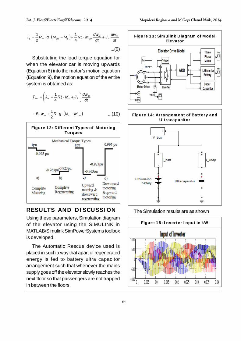
RESULTS AND DISCUSSIONUsing these parameters, Simulation diagramof the elevator using the SIMULINK inMATLAB/Simulink SimPowerSystems toolboxis developed.
The Automatic Rescue device used isplaced in such a way that apart of regeneratedenergy is fed to battery ultra capacitorarrangement such that whenever the mainssupply goes off the elevator slowly reaches thenext floor so that passengers are not trappedin between the floors.
Figure 13: Simulink Diagram of ModelElevator
Figure 14: Arrangement of Battery andUltracapacitor
Figure 15: Inverter Input in kW
65
Int. J. Elec&Electr.Eng&Telecoms. 2014 Mopidevi Raghava and M Gopi Chand Naik, 2014
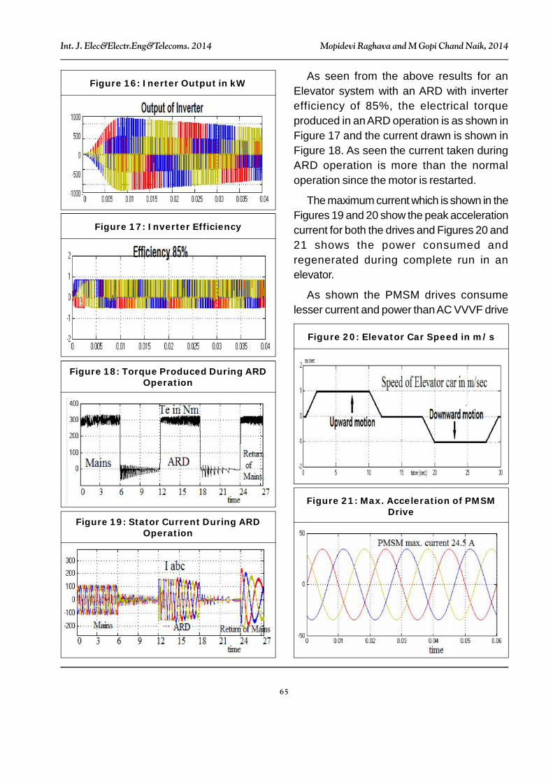
As seen from the above results for anElevator system with an ARD with inverterefficiency of 85%, the electrical torqueproduced in an ARD operation is as shown inFigure 17 and the current drawn is shown inFigure 18. As seen the current taken duringARD operation is more than the normaloperation since the motor is restarted.
The maximum current which is shown in theFigures 19 and 20 show the peak accelerationcurrent for both the drives and Figures 20 and21 shows the power consumed andregenerated during complete run in anelevator.
As shown the PMSM drives consumelesser current and power than AC VVVF drive
Figure 16: Inerter Output in kW
Figure 17: Inverter Efficiency
Figure 18: Torque Produced During ARDOperation
Figure 19: Stator Current During ARDOperation
Figure 20: Elevator Car Speed in m/s
Figure 21: Max. Acceleration of PMSMDrive
66
Int. J. Elec&Electr.Eng&Telecoms. 2014 Mopidevi Raghava and M Gopi Chand Naik, 2014
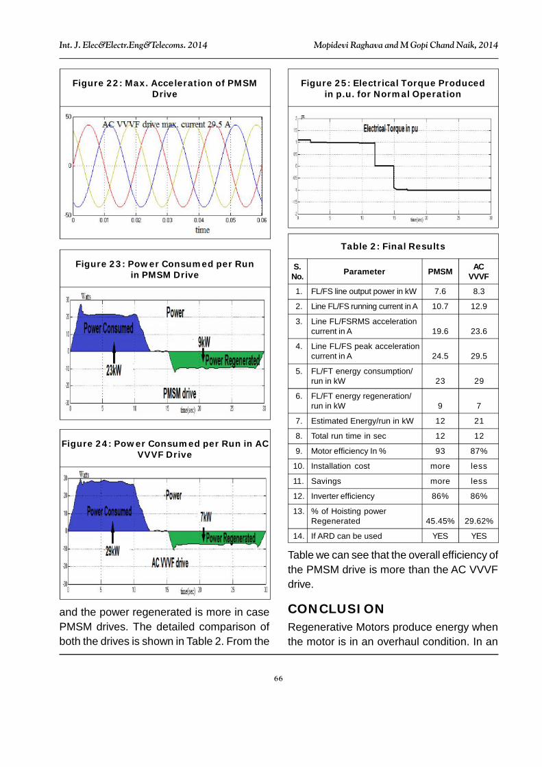
Figure 22: Max. Acceleration of PMSMDrive
Figure 23: Power Consumed per Runin PMSM Drive
Figure 24: Power Consumed per Run in ACVVVF Drive
Figure 25: Electrical Torque Producedin p.u. for Normal Operation
and the power regenerated is more in casePMSM drives. The detailed comparison ofboth the drives is shown in Table 2. From the
1. FL/FS line output power in kW 7.6 8.3
2. Line FL/FS running current in A 10.7 12.9
3. Line FL/FSRMS accelerationcurrent in A 19.6 23.6
4. Line FL/FS peak accelerationcurrent in A 24.5 29.5
5. FL/FT energy consumption/run in kW 23 29
6. FL/FT energy regeneration/run in kW 9 7
7. Estimated Energy/run in kW 12 21
8. Total run time in sec 12 12
9. Motor efficiency In % 93 87%
10. Installation cost more less
11. Savings more less
12. Inverter efficiency 86% 86%
13. % of Hoisting powerRegenerated 45.45% 29.62%
14. If ARD can be used YES YES
Table 2: Final Results
S.No. Parameter PMSM AC
VVVF
Table we can see that the overall efficiency ofthe PMSM drive is more than the AC VVVFdrive.
CONCLUSIONRegenerative Motors produce energy whenthe motor is in an overhaul condition. In an
67
Int. J. Elec&Electr.Eng&Telecoms. 2014 Mopidevi Raghava and M Gopi Chand Naik, 2014
elevator, this occurs when the motor is used tobrake a descending unit. Until recently, theelectricity generated was sent through a seriesof resisters that dissipated the energy as heatinto the machine room. With the introductionof regenerative drives, the energy producedcan be fed back into the building or power grid.Because the harmonics are purified, there isno line loss and 100% of the power thatisharnessed is usable.
However from the results it is clear that thatthe introduction of PMSM in the modernelevators shows that it not only consumeslesser energy per run but also regeneratesmore energy compared to the AC VVVF driveswhich are now mostly available in the market.
So PMSM regenerative drives eventhough are costlier than the rest save moreenergy than VVVF drives and with recentadvancements, they can also be used forheavy applications.
REFERENCES1. Gaiceanu M (2007), “Inverter Control for
Three-Phase Grid Connected Fuel CellPower System”, Compatibility in PowerElectronics, CPE’07, Digital ObjectIdentifier: 10.1109/CPE.2007.4296506,pp. 1-6.
2. Guo Y, Wang X, Lee H C and Ooi B T(1994), “Pole-Placement Control ofVoltage-Regulated PWM RectifiersThrough Real-Time Multiprocessing”,IEEE Trans. on Ind. Engineering, Vol. 41,No. 2, pp. 224-230.
3. Hombu M, Ueda S, Ueda A and MatsudaY (1985), “A New Current Source GTOInverter with Sinusoidal Output Voltage and
Current”, IEEE Trans. Ind. Applcat., Vol.21, pp. 1192-1198.
4. Inaba H, Nara S T, Takahashi H andNakazato M (1989), “High Speed ElevatorsControlled by Current Source InverterSystem with Sinusoidal Input and Output”,Elevator World, March, pp. 54-60.
5. Inaba H, Shima S, Ueda A, Ando T,Kurosawa T and Sakai Y (1985), “A NewSpeed Control System for DC MotorsUsing GTO Converter and its Applicationto Elevators”, IEEE Trans. Ind. Applcat.,Vol. 21, pp. 391-397.
6. Leonhard W (1996), Control of ElectricalDrives, Springer-Verlag, Berlin.
7. Murphy J M D and Tumbull F G (1988),Power Electronic Control of AC Motors,pp. 306-330, Pergamon Press, Oxford,England.
8. Nishimoto M, Dixon J W, Kulkarni A B andOoi B T (1996), “An Integrated Controlled-Current PWM Rectifier Chopper Link forSliding Mode Position Control”, IEEE,Ind. Appl. Soc. Annual Meeting, October,pp. 752-757.
9. Ooi B T, Guo Y, Wang X, Lee H C, NakraH L and Dixon J W (1991), “Stability ofPWM HVDC Voltage Regulator Based onProportional-Integral Feedback”, EPEFirenze’91, Vol. 3, pp. 3076-3081.
10. Sul S K and Lipo T A (1990), “Design andPerformance of a Digitally Based VoltageController for Correcting Phase”, IEEETrans. on Ind. Appl., Vol. 26, No. 3,pp. 434-440.
11. Uhrin R and Profumo F (1996), “StandAlone AC/DC Converter for Multiple

68
Int. J. Elec&Electr.Eng&Telecoms. 2014 Mopidevi Raghava and M Gopi Chand Naik, 2014
Inverter Applications”, Power ElectronicsSpecialists Conference, PESC’96Record, 27th Annual IEEE, Vol. 1, June 23-27, pp. 120-126.
12. Universal Power Analyzer PM 3000AUsers’ Manual (1997), VoltechInstruments, Abingndon, England.