COMPARATIVE STUDY OF MACHINABILITY CHARACTERISTICS DURING MACHINING NIMONIC...
37
COMPARATIVE STUDY OF MACHINABILITY CHARACTERISTICS DURING MACHINING NIMONIC C-263 WITH UNCOATED AND CVD MULTICOATED CARBIDE INSERTS Thesis submitted in partial fulfilment of the requirements for the Degree of B.Tech. In Mechanical Engineering By SANJEEB KUMAR NAYAK (110ME0031) NATIONAL INSTITUTE OF TECHNOLOGY ROURKELA 769008
Transcript of COMPARATIVE STUDY OF MACHINABILITY CHARACTERISTICS DURING MACHINING NIMONIC...

COMPARATIVE STUDY OF MACHINABILITY
CHARACTERISTICS DURING MACHINING NIMONIC
C-263 WITH UNCOATED AND CVD MULTICOATED
CARBIDE INSERTS
Thesis submitted in partial fulfilment of the requirements for the Degree of
B.Tech.
In
Mechanical Engineering
By
SANJEEB KUMAR NAYAK
(110ME0031)
NATIONAL INSTITUTE OF TECHNOLOGY
ROURKELA 769008

COMPARATIVE STUDY OF MACHINABILITY
CHARACTERISTICS DURING MACHINING NIMONIC
C-263 WITH UNCOATED AND CVD MULTICOATED
CARBIDE INSERTS
A Thesis submitted in partial fulfillment of the
Requirements for the degree of
Bachelor of Technology
In
Mechanical Engineering
By
SANJEEB KUMAR NAYAK (110ME0031)
Under the guidance of
Dr. S.GANGOPADHYAY
NATIONAL INSTITUTE OF TECHNOLOGY
ROURKELA, 769008

CONTENTS
Topics Pages
CERTIFIACTE i ACKNOWLEDGEMENT ii ABSTRACT iii LIST OF TABLES iv LIST OF FIGURES v
1. INTRODUCTION 1
NICKEL BASE SUPER ALLOY
1.1. MACHINABILITY OF NIMONIC ALLOY 2
1.1.1. Need for machining NIMONIC Alloy 2
1.1.2. Types and composition of NIMONIC Alloy 3
1.2. PROPERTY OF NIMONIC C-263 ALLOY 4
1.2.1. Advantage and Applications of NIMONIC Alloy 4
1.3. CHALLENGES IN MACHINING NIMONIC 5
1.4 CUTTING TOOL MATERIAL 5
1.4.1. Different Cutting Tool Materials 6
1.5. TOOL WEAR 7
1.6. DIFFERENT ENGINEERING APPLICATIONS OF NIMONIC C-263 8
2. LITERATURE REVIEW 9
MACHINABILITY STUDY OF NIMONIC ALLOY C-263
2.1. Effect of Machining Parameters on Surface Roughness 9
2.2. Effect of Machining Parameters on Tool Life 10
2.3. Objective of present work 11
3. EXPERIMENTAL METHODS AND CONDITIONS 12
3.1. Setup for Turning State 12
3.2. Cutting description 13
3.3. Designation Tool Holder 14
3.4. Work piece details 14
3.4.1. Composition 14
3.4.2. Properties 15
3.4.3. Application 15
3.5. DESCRIPTION OF EXPERIMENT 15
4. RESULTS AND DISCUSSION 17
4.1. CHIP THICKNESS RATIO 19
4.2. STUDY OF TOOL WEAR 22
5. CONCLUSION 26
6. REFERENCE 27

i | P a g e
NATIONAL INSTITUTE OF TECHNOLOGY
ROURKELA
CERTIFICATE
This is to certify that the thesis entitled, “COMPARATIVE STUDY OF MACHINABILITY
CHARACTER WHEN MACHINING NIMONIC C-263 WITH UNCOATED AND CVD
MULTI COATED CARBIDE INSERTS” submitted by Sanjeeb Kumar Nayak (110ME0031) in
partial fulfilment of the requirements for the award of Bachelor of Technology Degree in
Mechanical Engineering at National institute of at National institute Technology, Rourkela .The
authentic work carried out by him under my supervision and guidance.
To the best of my knowledge, the matter embodied in the thesis has not been submitted to other
Institute/University for the award of any Degree or Diploma.
Dr. S. Gangopadhyay
Department of Mechanical Engineering
Date. - 11th APRIL 2014 National Institute of Technology
Rourkela -769008

ii | P a g e
AKNOWLEDGEMENT
I am highly indebted to my mentor Dr. S. Gangopadhyay for providing the opportunity to work on
this project under his guidance. He has been great as a mentor and has motivated me throughout my
entire work duration .I am thankful to him for being so patience with me ad for providing Inspiring
guidance, constructive criticism and valuable suggestion to complete the project work.
I am also grateful to Mr. Kunal Nayak, Lab. assistant staff of production engineering laboratory and
Mr.Aveek Mohanty, M.Tech. Student of production engineering specialization for the help and
support during the experiment of bproject work. I am also thankful to all the teacher and staff of the
department of mechanical engineering for always being available for me for clear doubt or other issue
which hindering in my project work.
Last but not the least, my sincere thanks to all my friend who have been patiently extended all sort of
help for accomplishing this undertaking.
SANJEEB KUMAR NAYAK
ROLL NO - 110ME0031
Date. – 11th APRIL 2014 B.Tech, Mechanical Engineering
NATIONAL INSTITUTE OF TECHNOLOGY
ROURKELA -769008

iii | P a g e
ABSTRACT
Nickel base super alloy has the combined property of “high mechanical strength” and “High heat and
corrosion resistance” at elevated temperature. This is the reason for which Nickel based super alloy
are extremely used in 1. Aircraft gas turbine engine due to their superior mechanical property at an
elevated temperature, 2. Aerospace component which continuously suffer from Extreme temperature,
pressure and velocity for long period, 3. Submarine and chemical industries due to Superior
Chemical properties like resistance to corrosion and oxidation, 4. Heat exchanger as subjected to
high temperature. Super alloy are difficult to machine due to their high mechanical strength and low
thermal conductivity resulting tool wear during machining. Work hardening occur rapidly during
machining resulting notching. Chemical reaction occur at high cutting temperature produce
diffusion wear during machine. Low thermal conductivity of super alloy results tool wear, which
accelerate premature tool failure, short tool life, increase of cutting forces and poor quality of surface
finish. NIMONIC is high temperature low-creep super alloy .Major constituents of NIMONIC is
nickel , Chromium and cobalt which enhance the resistance to corrosion and oxidation for which
NIMONIC got higher chemical property compared to Inconel in which (5-10)% iron concentration
present. NIMONIC C-263 alloy has immense uses recent times as mentioned above hence it is
necessary to study the machinability aspect of super alloy in order to enhance and productivity of the
super alloy. Tool performance were studied ,when C-263 super alloy is machined under coated and
uncoated carbide tool insert at dry condition .The operation were performed keeping feed
(0.2mm/rev)and depth of cut (1mm) and varying cutting velocity (51-84)m/min.
iv | P a g e
LIST OF TABLES
Pages
TABLE 1. EXPERIMENTAL DETAILS 13 TABLE 2. TOOL DESIGNATION 14 TABLE 3. NIMONIC C-263 COMPOSITION 14 TABLE 4. CUT CHIP THICKNESS AT SPEED OF 51 m/min FOR 17 COATED AND UNCOATED TOOL TABLE 5. CUT CHIP THICKNESS AT SPEED OF 84 m/min FOR 17 COATED AND UNCOATED TOOL TABLE 6. FLANK WEAR (VB) AT SPEED OF 51 m/min FOR 18 COATED AND UNCOATED TOOL TABLE 7. FLANK WEAR (VB) AT SPEED OF 84 m/min FOR 18 COATED AND UNCOATED TOOL

v | P a g e
LIST OF FIGURES
FIGURE 1. DIFFERENT TYPE OF TOOL WEAR OBSERVED IN 8
CUTTING TOOL
FIGURE 2. EXPERIMENTAL SET UP 12
FIGURE 3. GRAPH BETWEEEN MACHINING DURATION AND 20
CUTTING SPEED OF 51 m/min ON CHIPTHICKNESS RATIO
OF UNCOATED AND MULTI COATED CARBIDE INSERT
FIGURE 4. GRAPH BETWEEEN MACHINING DURATION AND 21
CUTTING SPEED OF 51 m/min ON CHIPTHICKNESS RATIO
OF UNCOATED AND MULTI COATED CARBIDE INSERT
FIGURE 5. FLANK WEAR OBSERVE ON MICROSCOPE AT CUTTING 22
SPEED OF 51 m/min OF COATED AND UNCOATED INSERT
FIGURE 6. FLANK WEAR OBSERVE ON MICROSCOPE AT CUTTING 23
SPEED OF 51 m/min OF COATED AND UNCOATED INSERT
FIGURE 7. VARIATION OF MACHINING DURATION AND CUTTING 24
SPEED OF 51m/min ON FLANK WEAR OF UNCOATED AND
MULTI COATED CARBIDE INSERT
FIGURE 8. VARIATION OF MACHINING DURATION AND CUTTINF 25
SPEED OF 84 m/min ON FLANK WEAR OF UNCOATED AND
MULTI COATED CARBIDE INSER
1 | P a g e
INTRODUCTION
Nickel base super alloy are the most difficult material to machine for its high hardness, high
strength at elevated temperature, low thermal diffusivity .It has the tendency to react with tool
material resulting tool wear .At least 50% of nickel is present in Nickel base super alloy .The
percent of other elements are added to achieve of superior mechanical property .Wrought base
super alloy contain 10-20 %chromium, 7% Al and Ti, 5-15% Co in order to improve surface
stability. The superior properties in term of high temperature, corrosion resistance and high
strength-to-weight ratio it has a wide range of application in aerospace engine manufacture,
Turbine blade in power plant etc.
NIMONIC C-263 is basically nickel base super alloy which have high content of cobalt and
chromium but possess less amount of iron. The presence of Cr influence to have a unique
properties of the material in term of maintained mechanical properties and resistance to corrosion
at elevated temperature. Molybdenum is used for solid –solution strengthening. It is used for
aerospace equipment. The high work hardening rate ,resistance to penetration are the major
challenges for machining of NIMONIC C-263 super alloy .Machining of NIMONICC-263 the
tool has to go through tremendous heat, pressure and aberration resulting tool wear, flank wear
which leads to differ in the dimensional accuracy as well as surface integrity.
Nickel base super alloy are high corrosion resistance alloy. They resist shock and creep at
elevated temperature. Chromium (Cr) is used to for solid strengthening solution .Presence of
Tantalum (Ta) in the intermetallic compound improves the oxidation resistance and temperature
strength at extreme temperature
The nickel base super alloy has high mechanical properties 1. High tensile strength, 2. High
fatigue strength, 3. High yield strength. It has superior chemical properties at high temperature.
Resistance to corrosion and resistance.

2 | P a g e
1.1. MACHINABILITY OF NIMONIC C-263 ALLOY
Machinability is the ease of removal of material from work piece to an expected surface finish.
Machining performance of a material can determined by machinability.
Factors influence machinability
1. Mechanical properties
2. Physical properties
3. Chemical composition of the material
4. Shape and size of work piece
5. Cutting parameter
1. Speed
2. Feed
3. Depth of cut
Observed criteria for determine machinability
1. Surface roughness
2. Tool wear
3. Chip characteristic
4. Cutting forces
5. Cutting temperature
NIMONIC C-263 has superior properties that influence machinability .They work harden rapidly
during machining .they have the tendency to react with tool material during in. They have the
tendency to form BUE and the presence of abrasive carbide in the microstructure determine the
machinability of this nickel base super alloy NIMONIC C-263.
1.1.1. Need for machinability
Nickel base super alloy NIMONIC C-263 have superior mechanical property, high
strength and corrosion resistance for which it is widely used in aerospace application
,turbine blade, submarine for which it is a bit of costlier .During machining precision is
required in terms of surface finish ,shape with the minimal removal of material from the
work piece to achieve economic benefit. The machinability can be improved using
different cutting tool, coated and uncoated carbide insert tool provide a bit better
machinability
.

3 | P a g e
1.1.2. Types of NIMONIC alloy
1. NIMONIC 75
It has a good mechanical properties and oxidation resistance at elevated temperature.
Composition -Ni 76.0, Cr 20.0, Fe 4.0
2. NIMONICc80A
It has the same type of character as that of NIMONIC 75 but the addition of aluminum
and titanium hardened the material.it has good oxidation and corrosion resistance
property. The tensile and creep rupture point is large at elevated temperature.
Composition -Ni 76.0, Cr 19.5, Ti 2.4, Al 1.4
3. NIMONIC alloy 86
Nickel-chromium-molybdenum alloy having good formability and weldability.
Exceptional creep strength and oxidation resistance at high temperature up to 1000 °C
Composition - Ni 65.0 Cr 25.0, Mo 10.0, Cerium 0.03
4. NIMONIC alloy 90
A precipitation hardenable nickel-chromium-cobalt alloy having high stress rupture
strength and high creep resistance at a temperature of 920 de c. having good oxidation
and corrosion resistance
Composition - Ni 60.0, Cr 19.5, Co 16.0, Ti 2.5, Al 1.5
5. NIMONIC alloy 105
A precipitation hardenable nickel-chromium-cobalt alloy with molybdenum for solid
solution strengthening. It has relatively high amount of aluminum enhance the strength as
well as oxidation resistance.
Composition - Ni 54.0, Co 20.0, Cr 15.0, Mo 5.0, Al 4.7, Ti 1.3
6. NIMONIC alloy 115
It is similar to that of NIMONIC alloy 105 but the amount of aluminum and titanium is
high in order to have improve strengthening.
Composition - Ni 60.0, Cr 14.2, Co 13.2, Al 4.9, Ti 3.8, Mo 3.2
7. NIMONIC alloy C-263
A precipitation hardenable nickel-chromium-cobalt alloy with addition of molybdenum
for solid solution strengthening .high resistance to corrosion and oxidation up to 850 °C
Composition - Ni 51.0, Cr 20.0, Co 20.0, Mo 5.8, Ti 2.2, Al 0.5
4 | P a g e
1.2. PROPERTY OF NIMONIC C-263 ALLOY
Physical properties
Density, g/cm 3 - 8.36
Liquidus temperature, °C 1355
Solidus temperature, °C 1300
Specific Heat, J/kg, 461 in the range of 20-100 °C
Thermal properties
Thermal expansion co-efficient (21-100) 10.3 µm/m°C
Thermal conductivity 11.7 W/mK
Low thermal conductivity
1.3. ADVANTAGE AND APPLICATION OF NIMONIC C-263 ALLOY
Nickel base super alloy NIMONIC C-263 has the combine properties of high
“mechanical strength” and “high heat and corrosion resistance” at an elevated
temperature. The austenite nickel matrix reacts with Chromium (Cr), Cobalt (Co),
molybdenum (Mo) ,tungsten (W) to become alloy. Chromium present in the alloy reacts
with the oxygen present in the air and form a protective scale layer of Chromium Oxide
(Cr2O3).This protective layer prevent outward diffusion of metallic element.
Molybdenum and tungsten helps for solid solution strengthening at elevated temperature.
Precipitation hardening also strengthening the nickel base super alloy with the addition
of aluminum .
Application of NIMONIC Alloy
1. Gas turbine engines
2. Compounding of industrial furnace
3. Nuclear power plant
4. Tube supports in nuclear steam generators
5. Exhaust valve in internal combustion engine
6. Aerospace component
7. Submarine and Chemical industries
8. Heat exchanger
9. Food processing equipment
10. Petrochemical plant
5 | P a g e
1.3 CHALLENGES IN MACHINING NIMONIC C-263
Casting ,forging and other advanced technique are used to manufacture nickel base alloy
NIMONIC components .It is quite difficult to manufacture and machine intricate shaped
component part at reliable cost due to the following reasons
1. During machining high strength and hot hardness of NIMONIC alloy cause deformation
of cutting tool.
2. NIMONIC alloy get rapid work hardening during machining due to the austenite matrix.
This is the reason for tool wear at depth of cut line.
3. Localization of shear stress and formation of abrasive saw tooth edge resulting notching
of cutting tool. High dynamic shear strength is the reason behind notching of cutting tool.
4. Hard abrasive carbide like MC, M23C6 present in the microstructure of NIMONIC alloy
resulting abrasive related tool failure.
5. Low thermal diffusivity of the material resulting high temperature gradient in the tool tip.
This is due to the localization of cutting temperature (>1000°C) at the tool tip.
6. The work piece get welded with the cutting tool edge resulting unstable build up edge
formation ,which hamper the surface roughness of work piece during machining.
7. NIMONIC has the tendency to react with cutting tool material at elevated temperature
causing tool wear.
8. Presence of the abrasive particle in the microstructure resulting rapid tool wear due to the
different wear mechanism
9. The combined property of mechanical strength and resistance to corrosion at elevated
temperature of NIMONIC C-263 resulting poor machinability.
1.4 CUTTING T OOL MATERIAL
During machining NIMONIC C-263 the cutting tool is subjected to extreme mechanical and
thermal stress near to the cutting tool which accelerate tool wear .Notching at the nose and depth
of cut line, flank wear, Crater wear, chipping are the typically observed tool failure during
machining of NIMONIC C-263 alloy. To overcome this challenges the cutting tool should have
enough hot hardness to withstand high temperature during high speed condition.
Coated carbide tool, ceramic, CBN/PCBN tool are generally used for high speed machining of
NIMONIC C-263 alloy while uncoated carbide tool are used for low speed machining condition.
Effective machining of work piece can be achieved depending up on the type of cutting tool
material used while machining
6 | P a g e
1.4.1. Different Cutting Tool Materials
a. Coated and uncoated carbide tool
Straight and mixed grade carbide are two often used carbide tool material for commercial
machining purpose. The straight carbide tool have cobalt 6% by weight, 94% WC with the range
of cobalt 5-15 % .The mixed grade carbide are Titanium carbide (TiC),tantalum carbide(TaC).
Titanium carbide improve the wear resistance of carbide tool. The tough ness of the carbide id
reduced with the increase concentration of titanium. The hot hardness of the tool can be
improved with inclusion of tantalum carbide. The plastic deformation can be prevented while
machining at high speed. High cobalt content and coarse grain tungsten carbide are required to
resist high shock.
The performance of the cutting tool can be achieved using ceramic coating. They have high
temperature resistance property and resistance to diffusion wear, high hot hardness, oxidation
wear resistance. The lowering cutting temperature during machining can be achieved due to the
improved lubricating properties of chip –tool and toll-work piece interface. Higher cutting speed
also achieved using coated ceramic tool.
b. HSS (High speed steel)
High carbon ferrous alloy with the constituent of Cr, Co, W, Mo and V. In the form of Cast,
wrought and sintered (using power metallurgy technique) HSS are available. It is of less
expansive compared to other cutting tool material. Fracture toughness and fatigue resistance
were the feature properties of HSS .It is applicable for a short range of velocity i.e. 30-50 m/min
due to its limited wear resistance and chemical stability.
It is classified depending up on the dominating alloying element
T-type steels having tungsten as the dominant alloying element and M-type steels molybdenum
is the dominant alloying element.
c. Cemented carbide
Mixing , compacting and sintering are the process of manufacturing cemented carbide cutting
tool material .In case of Sintering process primarily tungsten carbide (WC) and cobalt (Co)
powders were used. For tungsten carbide (WC) grain Co acts as a binder. The carbide tool have
good electrical and thermal conductivity as they have strong metallic character. These cutting
tool are chemically stable. They possess high stiffness and lower friction, and operate at higher
cutting velocities compared to HSS. These material are expansive and brittle in nature. Generally
used for machining gray cast iron, nonmetallic material and nonferrous metal. M grade carbides
are alloyed with tungsten carbide (WC) to have the application in machining austenitic stainless
steel. The maximum hardness and toughness position of a material is achieved from the number
assigned to grade with in a group. P grades are rated from P01 to P50, M grades from M10 to
M40, and K grades from K01 to K40. Cobalt percentage and grain size of carbide determine the
performance of carbide cutting tool.

7 | P a g e
d. Cermets
Cermets are ceramic material in metallic binder. Co and Mo are the softer binder which
held the constituent hard particles of TiC ,TiN, or TiCN..These material are operated on
high cutting velocities and hence suitable for machining steel, cast iron. They possess
lower thermal conductivity and resistance to fracture
e. Ceramic
Ceramic are nonmetallic material and subjected to extreme temperature during
machining. The uniqueness of this type material is to retain the stiffness and hardness of
the material at elevated temperature equal to 1000° C.
Basically 2 types of ceramic tool available for commercial machining purpose
1. Alumina-based ceramics which consists of pure oxide, mixed oxides, and silicon carbide
(SiC) whisker reinforced alumina ceramics.
2. Silicon nitride-based ceramics
1.5. TOOL WEAR
Machining for a prolonged period the cutting tool destroyed due to high strength and
temperature resistance of work piece .major tool wear studied during machining were
A. CRATER WEAR
During machining chip slide over the tool face resulting formation of concave section in
the chip tool interface .Crater wear increase rake angle resulting easier machining but
simultaneously it reduces the strength of cutting tool which influences tool failure during
machining.
B. FLANK WEAR
The friction between work piece surface and tool flank resulting flank wear at the tool
flank .it generally appear in the form of wear land which affect machining. The increase
in flank wear resulting in cutting force which in excess resulting tool failure. VB>0.3mm
tool failure occur.
C. CORNER WEAR
This tool wear took place in the tool corner.it is also called a part of wear land as there
were no definite boundary between flank wear land and corner wear .The reduction of
cutting tool length results in increase in the dimension of machined surface gradually

8 | P a g e
Apart from this wear other types of wear are present, these were
Adhesion wear –the fragment of work piece welded with tool surface at heigh
temperature during machining is called adhesion wear
Abrasion wear –the bottom part of chip rub against the tool surface and part of it is
break away which is called abrasive wear.
Diffusion wear –chip and tool diffuses during machining is called diffusion wear
TYPES OF WEAR IN CUTTING TOOL
Fig.1. Different types of tool wear observed in cutting tool
1.6. DIFFERENT ENGINEERING APPLICATIONS OF NIMONIC C-263
1. Aircraft gas turbine engine due to their superior mechanical property at an elevated
temperature
2. Aerospace component which continuously suffer from Extreme temperature, pressure and
velocity for long period.
3. Submarine and chemical industries due to Superior Chemical properties like resistance to
corrosion and oxidation.
4. Heat exchanger as subjected to high temperature. Super alloy are difficult to machine due
to their high mechanical strength and low thermal conductivity resulting tool wear during
machining.

9 | P a g e
2 LITERATURE REVIEW
2.1. EFFECT OF CUTTING PARAMETER ON SURFACE ROUGHNESS
DURING MACHINING ON NIMONIC.
Ezilarasan et al. (2013) carried out analysis of process parameter and the influence of cutting
speed ,feed and depth of cut on surface roughness in the dry machining of NIMONIC C-263 .It
was observe that Surface roughness decrease with increase of cutting speed and depth of cut and
at medium level of feed . Surface roughness Increase with increase of feed rete and decrease
with increase of cutting speed. Best surface roughness achieved at higher depth of cut keeping
low level of feed rate.
EzugwuZUGWU et al.( 2008) studied the performance of PVD coated multilayer tool
(TiN/TiCN/TiN) and single layer TiAlN tool on machining of NIMONIC C-263 at high speed
condition .it has been observed that single layer provide better surface finish compared to
multilayer PVD inserted tool during high speed and depth of cut condition. The variation in tool
geometry and cutting condition has neglected effect on surface roughness.
Ezilarasan et al. (2012) observe the influence of cutting parameter and cutting time on the
surface roughness of the C-263 super alloy while turning. It has been observed that the surface
roughness improves up to a speed of 190m/min after which surface roughness increase with
speed. The least measured surface roughness value was 1.9µm .The increase cutting speed
increase cutting temperature, the low thermal conductivity of the work piece accumulate
temperature at the cutting tool edge resulting tool wear .This is the reason behind resulting high
surface roughness.
Ezugwu et al. (2003) observe that the effect of concentration of coolant on cutting tool during
machining NOMINIC C-263 using triple coated TiN/TiCN/TiN carbide insert. It was observed
that the varying concentration of coolant has not significantly improve surface roughness of
work piece.
Okeke et al. (2002) studied the effect of multicoated TiN/TiCN/TiN and single coated TiAlN
carbide insert on machining of NIMONIC C-263 under high speed condition in wet condition. It
was observed that the single coated TiAlN carbide insert tool provide better surface compared to
multi coated TiN/TiCN/TiN carbide tool. Single layer tool has high oxidizing temperature
resulting lower surface roughness below 2.54 mm depth of cut. Lower depth of cut with cutting
speed 51m/min-68 m/min mechanical surface damage occurs.
Ezugwu et al. (2000) observe that the effect of coating material on machinability of NIMONIC
C-263.IT was observed that the all grades of coated carbide toll has given uniform surface
roughness value under the rejection criterion.

10 | P a g e
Vealyudham et al. (2011) investigate the effect of cutting parameter on machining of NIMONIC
C-263 super alloy. It was observed that the process parameter feed rate has highest S/N ratio and
the significant effect on surface roughness compared to cutting speed and depth of cut.
2.2. EFFECT OF CUTTING PARAMETER ON TOOL WEAR DURING
MACINING NIMONIC
Ezilarasan et al .(2013) carried the analysis and measurement of the cutting parameter and the
influence of cutting speed on tool were studied .It has been concluded that at lower cutting speed
there might be the adhesion of chip to the tool surface due to the weld pressure between chip and
tool surface.
Ezugwu et al. (2004) carried out effect of coolant on the tool wear studied 3-6 % coolant flank
wear takes place while 9% coolant chipping at the cutting edge the mode of tool failure, increase
of cutting speed reduces tool chip interface resulting increase of temp at small zone cause
compressive stress at cutting tool edge leads to tool failure. Speed increase low thermal
conductivity of material shifts towards tool edge resulting tool wear cause tool failure.
Ezugwu et al.(2008) ingle coated carbide tool Higher thermal conductivity increase abrasive
wear lead to adhesion wear and accelerating flank wear in speed of 54 -68 m/min resulting
premature tool failure, short tool life . While multilayer tool have high mechanical strength to
cutting edge due to high hardness and thick layer coating.
Ezilarasana et al (2013) studied the influence of cutting parameter on tool wear .feed rate
influence flank wear, for low flank wear low level of feed rate and DOC with middle speed is
required.
Ezugwu et al.(2002) studied the influence of coated and uncoated carbide insert am machining of
NIMONIC C -263 at low cutting speed of 54m/min.it was observed that The higher thermal
conductivity, hardness and friction coefficient of single layer TiAlN coated insert resulted in
better tool life than that of multilayer at lower depth of cut of less than 1.25 mm. Thicker layer of
multilayer coated tools provided high resistance to wear at high cutting speed of 68 m/min and at
depth of cut 2.54 mm, hence outperforming single layer coated inserts.
Okeke et al. (2000) carried out experiment to determine the performance of PVD coated carbide
insert when machining a NIMONIC C-263 alloy at high speed condition. Multi-layer
TiN/TiCN/TiN coated carbide insert with positive, chamfered and honed edges performed better
in terms of tool life than that with similar tool having no edge protection and double positive
edges. Feed rate has significant influence on tool life. Tool wear decrease with decrease feed rate
while increase with increase of depth of cut and cutting speed.

11 | P a g e
2.3. OBJECTIVE OF THE WORK
From the literature review it has been clear that a lot of study has been carried out for nickel
base super alloy Inconel 718, and Inconel 825.There exist a lot to find the influence of cutting
parameter on machining NIMONIC C-263.An attempt was made to study comparatively the
machining character of NIMONIC C-263 in terms of tool wear and character of chip
morphology. During machining cutting speed was varied keeping feed and depth of cut constant
for both the cutting tool material with different time interval .the object of the work is to find
1. Effect of cutting parameter on surface roughness during machining of NIMONIC C-263
while Uncoated ISO P30 grade cemented carbide and CVD deposited multilayer coating
of TiN/TiCN/Al2O3/ZrCN tool wear used.
2. Effect of cutting parameter on tool wear during machining of NIMONIC C-263 using
different tool
3. Effect of cutting parameter on chip character during machining of NIMONIC C -263
during machining at constant feed and depth of cut.

12 | P a g e
3. EXPERIMENTAL METHODS AND CONDITIONS
The turning of NIMONIC C-263 was carried out using coated and uncoated carbide insert in the
HMT NH26 lathe machine. The grade of cutting tool material were specified below. The
experiment was proceed with varying cutting speed of VC 51 m/min and 84 m/min keeping
constant feed of 0.2 mm/rev and depth of cut 1mm respectively. ISO SSBR 2020K12
(Kennametal, India) tool holder is used for the experiment. A heavy duty Lathe machine was
used for the turning of NIMONIC C-263under dry condition. A comparative tool performance
was studied using uncoated and CVD multilayer coated carbide ceramic insert .The set fig of the
experimental was given below
3.1. THE EXPERIMENTAL SET UP
Fig.2. Experimental set up for machining.

13 | P a g e
Experimental condition for turning
Work piece material NIMONIN C-263
Inserts used Uncoated ISO P30 grade cemented carbide
and CVD deposited multilayer coating of
(TiN/TiCN/Al2O3/ZrCN)
designation of insert SCMT 120408
Geometry of tool −6°, −6°, 6°, 6°, 15°, 75°, 0.8 (mm)
Cutting velocity 51m/min,84m/min
Cutting feed (constant) 0.2 mm/rev
Depth of cut 1mm
Cutting condition Dry
Table 1 - Experimental details
3.2. CUTTING TOOL DESCRIPTION
Designation of tool
SCMT 12 04 08
S Stands for square shape insert =90o
C stands for clearance angle =7o
M stands for medium tolerance=+/- 0.005”
T stands for, central hole and with groove
12 which means each cutting edge length is 12 mm
04 nominal thickness insert is 4mm
08 means the nose radius of 0.8 mm

14 | P a g e
Table 2. Tool designation
Sl. no. Cutting tool ISO grade
specification
Composition
1 Uncoated cemented
carbide insert P30
SCMT120408 WC+Co+TiC+TaC
2 CVD deposited
multilayer coated tool
SCMT120408 TiN/TiCN/Al2O3/ZrCN
Uncoated ISO P30 grade cemented carbide and CVD deposited multilayer coating of
TiN/TiCN/Al2O3/ZrCN from the substrate to top layer of the tool were used during the
dry machining condition. ZrCN has the antifriction property and possess excellent
toughness suitable for better tool life .Owing to its excellent toughness and anti-friction
properties, ZrCN is used as a top layer. Both uncoated and coated inserts were
commercially available tools with ISO insert designation of SCMT 120408. Positive rake
angle and strong cutting edge used at medium to high feed.
3.3. TOOL HOLDER DESIGNATION
ISO SSBR 2020K12 (Kennametal, India)
3.4. WORK PIECE DETAILS
A cylindrical shaped of 75mm diameter and 195 mm of length of NIMONIC C-263 super
alloy was the work material for the machining operation. The chemical Composition of the work
piece was given in the table
3.4.1. Composition of NIMONIC C-263
Table 3. Composition
Compound Al C Co Cr Mo Ni Ti
Nominal
wt.%
0.45
0.06
20.
20
5.85
Bal
2.15
15 | P a g e
3.4.2. Properties
I. Low thermal conductivity
II. High resistance to corrosion and oxidation at elevated temperature
III. High temperature low creep of work material.
IV. Work hardening rate is high.
3.4.3. Application
1. Unique property of mechanical strength and corrosion and oxidation resistance at extreme
temperature and pressure is used to serve in aerospace engine manufacturing, the turbine
components and the compounding of furnace.
2. The superior chemical property helps to use of the material n chemical industries and in
submarine
DESCRIPTION OF THE EXPERIMENT
P 30 grade cemented carbide generally possess high hardness, toughness and wear resistance
characteristics. The coated and uncoated carbide insert off ISO grade SCMT 120408 tool has
been used for the turning of NIMONIC C-263 in dry condition.
In the first phase of experiment the Uncoated cemented carbide insert P30 tool is used for
machining purpose with cutting speed 0f 51m/min a, constant feed of 0.2mm/rev and depth of
cut 1mm.the experiment were carried out for 30 sec. then the chip is collected for study chip
characteristics like size, shape, color, chip thickness and chip reduction coefficient .Chip
thickness ratio is the ratio between uncut chip thickness to the cut chip thickness, denoted by
“r” .cut chip thickness is measured in Vernier calipers while the uncut chip thickness is obtain by
the formula tuncut=f.sin(Φ),where f is feed and Φapproach angle The tool life can be observed
based up on the average flank wear measured on the stereo zoom optical microscope .VB=0.3
mm criteria is used for average flank wear calculation. The carbide tool is cleaned for further
experiment.
The same experiment were conducted for the cutting speed 0f 51m/min keeping all other
parameter constant for 60 second.in the similar fashion the chip is collected and the tool wear is
measured in the stereo zoom optical microscope. The carbide insert is again cleaned for 15 min
and then the experiment were carried out for another 30 second and repeat the observation
technique.
In the second phase of experiment the uncoated cemented carbide insert P30 tool is used for
machining NIMONIC C -263 with cutting speed of 84m/min ,keeping depth of cut 1mm and
feed rate of 0.2 mm/rev. The tool wear is measured based upon the average flank wear using
VB=0.3mm criteria and the chip were collected for further observation ,then the tool re removed

16 | P a g e
and cleaned in the similar manner as in case of phase one. The experiment were carried out for
another 60 second followed by another 90 second keeping cutting parameter speed 86m/min,
feed 0.2mm/rev and depth of cut 1mm and same observation technique is followed.
For CVD deposited multilayer coated tool both the two phase of experiment were conducted and
the same observation technique is followed. And the observe result is tabulated for further
calculation.

17 | P a g e
4. RESULTS AND DISCUSSION
For cut chip thickness
Table 4. Values of cut chip thickness for different machining duration with the cutting
parameter of, cutting speed (Vc)-51 m/min,feed-0.2mm/rev, depth of cut 1mm
Machining duration ,s Cut chip thickness ,µm
Uncoated Coated
30 0.3393 0.2685
90 0.3876 0.3709
120 0.4662 0.4501
Table 5. Values of cut chip thickness for different machining duration with the cutting
parameter of, cutting speed (Vc)-84 m/min,feed-0.2mm/rev, depth of cut 1mm
Machining duration (s) Cut chip thickness(µm)
Uncoated Coated
30 Tool fails 0.2144
90 0.3458
120 0.3825

18 | P a g e
For flank wear
Table 6. Values of flank wear for different machining duration with the cutting parameter
of cutting speed (Vc)-51 m/min,feed-0.2mm/rev, depth of cut 1mm
Machining
duration (s)
Flank wear (VB) mm
Uncoated Coated
30 0.235 0.17
90 0.325(tool fail) 0.185
120 0.25
Table 6. Values of flank wear for different machining duration with the cutting parameter
of cutting speed (Vc)-84 m/min,feed-0.2mm/rev, depth of cut 1mm
Machining
duration (s)
Flank wear (VB) mm
Uncoated Coated
30 0.45 (tool fails ) 0.17
90 0.21
120 0.42(tool fails)

19 | P a g e
4.1. CHIP THICKNESS RATIO
Machining parameter has a great influence in chip thickness ratio which is
observed during machining of NIMONIC C-263 at different cutting speed of
(51-84) m/min with coated and uncoated carbide inserts. With the increase of
machining time chip thickness ratio decrease due to the formation of tool wear
resulting thick chip thickness. At higher cutting speed chip thickness ratio increase as
speed increase ,reduction of coefficient of friction between chip tool interface takes
place resulting reduction of shear zone or cut chip thickness ultimately increase chip
thickness ratio. In the similar fashion Multilayer tool also produce reduced shear
zone which increase chip thickness ratio compared to uncoated tool.At higher
cutting speed chip thickness ratio increase.
The uncoated carbide at 84m/min cutting speed while machining NIMONIC C-263,
chip thickness ratio decrease after the duration of 90s.When cutting speed increase
from 51 to 84 m/min chip thickness ratio increase. The increase in cutting speed
decrease the chip tool inter face friction.
Uncut chip thickness, tuncut = f.sin(Φ), where f is feed and Φapproach angle
f = 0.2 mm/rev, approach angle is 75o
Cut chip thickness is measured from Vernier calipers

20 | P a g e
Figure 3. Effect of machining duration and cutting speed on chip thickness ratio for coated
and uncoated ceramic carbide inserts.
0
0.1
0.2
0.3
0.4
0.5
0.6
0.7
0.8
0 20 40 60 80 100 120 140
uncoated
coated
ch
ip t
hic
knes
s ra
tio
machining duration , s
Vc- 51m/min f - 0.2 mm DOC-1mm

21 | P a g e
Figure 4. Effect of machining duration and cutting speed on chip thickness ratio for coated
and uncoated ceramic carbide inserts.
0
0.1
0.2
0.3
0.4
0.5
0.6
0.7
0.8
0.9
1
0 20 40 60 80 100 120 140
coated
coated
c
hip
th
ickn
ess
rat
io
machining duration ,s
Vc- 84m/min f - 0.2 mm DOC-1mm

22 | P a g e
4.2. STUDY OF TOOL WEAR
Figure 5. Flank wear observed on optical microscope at speed of 51m/min of coated and uncoated
carbide tool
Machining
duration ,s
Uncoated tool Coated tool
Flank surface image of insert at
cutting speed of 51 m/min
30
60
90

23 | P a g e
Figure 6. Flank wear observed on optical microscope at speed of 84 m/min of coated and uncoated
carbide tool
Machining
duration ,s
Uncoated tool Coated tool
Flank surface image of insert at
cutting speed of 51 m/min
30
60
TOOL FAILS
90
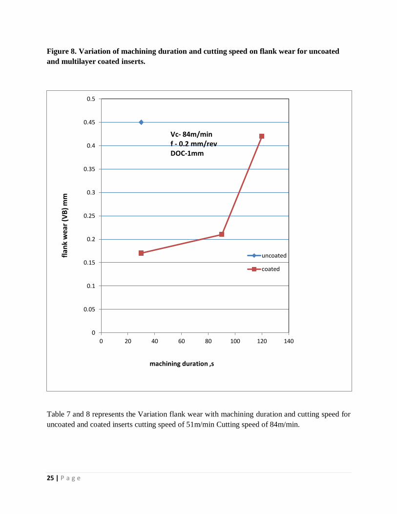
Flank wear studied in the optical stereo zoom optical microscope at 40 X zoom at Variable
cutting speed of 51m/min and 84 m/min keeping depth of cut 1mm and feed rate 0.2mm/rev ,the
studied figure were in the figure 5and 6 respectively .
Crater wear and flank wear are observed during machining of C-263 alloy at cutting speed of 51
m/min and 84 m/min. Uncoated tool fail after the machining of 90 sec at the speed of 51m/min
whereas multicoated tool can perform without tool failure . for the cutting speed of 84m/min the
catastrophic tool failure occur at the early stage of the uncoated tool where the multi coated tool
provide tool life upto 90sec then it fails. Increase in machining speed and duration flank wear
increase for both coated and uncoated tool

24 | P a g e
Figure 7. Variation of machining duration and cutting speed on flank wear for uncoated
and multilayer coated inserts.
0
0.05
0.1
0.15
0.2
0.25
0.3
0.35
0 20 40 60 80 100 120 140
uncoated
coated
Vc- 51m/min f - 0.2 mm DOC-1mm
machining duration ,s
fl
ank
we
ar (
VB
),m
m
25 | P a g e
Figure 8. Variation of machining duration and cutting speed on flank wear for uncoated
and multilayer coated inserts.
Table 7 and 8 represents the Variation flank wear with machining duration and cutting speed for
uncoated and coated inserts cutting speed of 51m/min Cutting speed of 84m/min.
0
0.05
0.1
0.15
0.2
0.25
0.3
0.35
0.4
0.45
0.5
0 20 40 60 80 100 120 140
uncoated
coated
Vc- 84m/min f - 0.2 mm/rev DOC-1mm
machining duration ,s
f
lan
k w
ear
(VB
) m
m

26 | P a g e
5. CONCLUSION
The present work on machinability of NIMONIC C-263 was performed with variable cutting
speed and tool coating and their effect in tool wear and chip reduction coefficient was studied
and the following inference were made ,these are
1. Chip thickness ratio increase with increase of cutting speed due to the reduction of shear
zone.
2. At lower cutting speed chip thickness ratio is high due to the higher coefficient of friction
between Tool Chip inter face resulting thick cutting chip thickness.
3. Flank wear increase with increase of cutting speed and machining time and can
minimized with the CVD multilayer tool insert.
4. From the above experiment it is recommended that the use of coated carbide tool for the
machining of Super alloy C-263.

27 | P a g e
REFERANCE
[1]. Arunachalam, R. and Mannan, M. A. (2000), Machinability of nickel-based high
temperature alloys, Machining Science and Technology, Vol. 4(1), pp.127-168.
[2]. C. Ezilarasan,An experimental analysis and measurement of process performancesin
machining of NIMONIC C-263 super alloy, Measurement 46 (2013) 185–199
[3]. C. Ezilarasan, Effect of Machining Parameters on Surface Integrity in Machining
NIMONIC C-263 Super Alloy Using Whisker-Reinforced Ceramic Insert, JMEPEG
(2013) 22:1619–1628
[4]. Choudhury, I.A. and El-Baradie, M.A. (1998), Machinability of nickel-base super
alloys: a general review, Journal of Materials Processing Technology, Vol. 77(1),
pp.278-284
[5]. E.O. Ezugwu, The machinability of nickel-based alloys: a review, Journal of
Materials Processing Technology 86 (1999) 1 – 16
[6]. Ezugwu, E.O. and Okeke, C.I. (2000a), Effects of coating materials on the
machinability of a nickel base, C-263, alloy. Tribology Transactions, Vol. 43(3),
pp.549-553.
[7]. Ezugwu, E.O. and Okeke. C.I. (2000b), Performance of PVD Coated Carbide Inserts
When Machining a Nimonic (C-263) Alloy at High Speed Conditions, Tribology
transactions, Vol. 43(2), pp.332-336.
[8]. Ezugwu, E.O. and Okeke, C.I. (2002), Behavior of coated carbide tools in high speed
machining of a nickel base alloy, Tribology Transactions, Vol. 45(1), pp.122-126.
28 | P a g e
[9]. Ezugwu, E.O., Wang, Z.M. and Machado, A.R. (1998), the machinability of nickel-
based alloys: a review. Journal of Materials Processing Technology, Vol. 86(1), pp.1-
16.
[10]. Ezugwu, E.O., Bonney, J. and Olajire, K.A. (2004), the effect of coolant
concentration on the machinability of nickel-base, nimonic C-263 alloy. Tribology
Letters, Vol. 16(4), pp.311-316.
[11]. Ezilarasan, C. and Velayudham, A. (2013), An experimental analysis and
measurement of process performances in machining of nimonic C-263 super
alloy, Measurement, Vol. 46(1), pp.185-199.
[12]. Ezilarasan, C., Zhu, K., Velayudham, A. and Palanikumar, K. (2011), Assessment
of Factors Influencing Tool Wear on the Machining of Nimonic C-263 Alloy with
PVD Coated Carbide Inserts, Advanced Materials Research, Vol. 291, pp.794-799.
[13]. I.A. Choudhury, Machinability of nickel-base super alloys: a general review, Journal of
Materials Processing Technology 77 (1998) 278 – 284
[14]. Podder, B. and Paul, S. (2008), Effect of machining environment on machinability of
Nimonic 263 during end milling with uncoated carbide tool, International Journal of
Machining and Machinability of Materials, Vol. 3(1), pp.104-119.
[15]. Podder, B. and Paul, S. (2012), Improvement of machinability in end milling of Nimonic
C–263 by application of high pressure coolant, International Journal of Machining and
Machinability of Materials, Vol. 11(4), pp.418-433.