
COMPARATIVE STUDY OF HYDROCARBON FUEL REFORMING …The system temperature for cracking the feedstock...
13
Journal of Engineering Sciences, Assiut University, Vol. 35, No. 3 pp. 801-813, May 2007 801 COMPARATIVE STUDY OF HYDROCARBON FUEL REFORMING PROCESSES AND PRODUCTION YIELDS OF SYNTHESIS GASES OF H 2 , CO 2 AND CO Zohair Khalaf Ismail, Ph.D. Department of Chemical Engineering; Faculty of Engineering Technology Al-Balqa Applied University; Marka-Amman, Box: 15008, Jordan (Received November 27,2006 Accepted April 28,2007 ) Theoretical study was conducted to investigate the distinction between cracking systems process technologies. The purpose is to feed pure hydrogen gas to the fuel cell as the renewable energy power source. Three types fuels of Hydrocarbon were involved namely gasoline, iso-octane and diesel. Theoretical calculations and synthesis gases of hydrogen, carbon dioxide and carbon monoxide were carried on. Steam reforming process of gasoline achieved a conversion of 68%, 75% for iso-octane and 55% for diesel. Auto thermal reforming produced 55% of H 2 for gasoline via 35% for iso-octane and diesel. The process of dry reforming produced 50% of H 2 for gasoline and 35% for iso-octane and diesel. The amounts of CO2 were analyzed for the cracking processes of the same gases. CO 2 generated in steam reforming was 40, 35 for iso-octane and 25% for diesel. Auto thermal reforming amount was 25% of CO 2 for gasoline and 28% for iso-octane and 40% for diesel. Dry reforming process reached an amount of gas of 35% of gas for steam reforming process of gasoline and 30 for iso-octane and 25% for diesel. Generation of CO gas for gasoline, iso-octane and diesel were also performed. Steam reforming processes contain 30%, 30%, 35%; respectively. Auto thermal cracking produces 30%, 30%, 45% of CO; respectively and in comparison with 35%, 25%, 44% of CO from dry reforming type processes. Data regarding cracking reforming chemical process [1, 2] were evaluated and recognized some disagreement. KEY WORDS: Steam reforming; Auto thermal; Dry reforming; Diesel; iso-octane; gasoline. INTRODUCTION Fuel cells are promising technology that can provide heat and electricity as long as fuel (hydrogen) is supplied [3]. Hydrogen possibly withdrawn from hydrocarbons by applying adequate heat necessary to separate the hydrogen form hydrocarbons is due to the fact that it is one of its main ingredients [3]. Small scale chemical plants usually use auto-thermal chemical process since it satisfies and fits the reactor criteria. The fuel cell which is the main part of the alternative power source system demand the use of pure hydrogen; that is the output of
Transcript of COMPARATIVE STUDY OF HYDROCARBON FUEL REFORMING …The system temperature for cracking the feedstock...

Journal of Engineering Sciences, Assiut University, Vol. 35, No. 3 pp. 801-813, May 2007
801
COMPARATIVE STUDY OF HYDROCARBON FUEL REFORMING PROCESSES AND PRODUCTION YIELDS OF
SYNTHESIS GASES OF H2, CO2 AND CO
Zohair Khalaf Ismail, Ph.D. Department of Chemical Engineering; Faculty of Engineering Technology
Al-Balqa Applied University; Marka-Amman, Box: 15008, Jordan
(Received November 27,2006 Accepted April 28,2007 )
Theoretical study was conducted to investigate the distinction between
cracking systems process technologies. The purpose is to feed pure
hydrogen gas to the fuel cell as the renewable energy power source. Three
types fuels of Hydrocarbon were involved namely gasoline, iso-octane and
diesel. Theoretical calculations and synthesis gases of hydrogen, carbon
dioxide and carbon monoxide were carried on. Steam reforming process
of gasoline achieved a conversion of 68%, 75% for iso-octane and 55%
for diesel. Auto thermal reforming produced 55% of H2 for gasoline via
35% for iso-octane and diesel. The process of dry reforming produced
50% of H2 for gasoline and 35% for iso-octane and diesel. The amounts of
CO2 were analyzed for the cracking processes of the same gases. CO2
generated in steam reforming was 40, 35 for iso-octane and 25% for
diesel. Auto thermal reforming amount was 25% of CO2 for gasoline and
28% for iso-octane and 40% for diesel. Dry reforming process reached
an amount of gas of 35% of gas for steam reforming process of gasoline
and 30 for iso-octane and 25% for diesel. Generation of CO gas for
gasoline, iso-octane and diesel were also performed. Steam reforming
processes contain 30%, 30%, 35%; respectively. Auto thermal cracking
produces 30%, 30%, 45% of CO; respectively and in comparison with
35%, 25%, 44% of CO from dry reforming type processes. Data
regarding cracking reforming chemical process [1, 2] were evaluated and
recognized some disagreement.
KEY WORDS: Steam reforming; Auto thermal; Dry reforming; Diesel;
iso-octane; gasoline.
INTRODUCTION
Fuel cells are promising technology that can provide heat and electricity as long as fuel
(hydrogen) is supplied [3].
Hydrogen possibly withdrawn from hydrocarbons by applying adequate heat
necessary to separate the hydrogen form hydrocarbons is due to the fact that it is one of
its main ingredients [3].
Small scale chemical plants usually use auto-thermal chemical process since it
satisfies and fits the reactor criteria. The fuel cell which is the main part of the
alternative power source system demand the use of pure hydrogen; that is the output of

Zohair Khalaf Ismail 802
hydrocarbon fuel cracking system with minimum sulfur, as well as natural carbon. By
the time that the hydrogen power system sees the light then it would be the source of
power that may be adopted by many governments all over the world. Therefore, an
efficient chemical process power plants to renovate hydrocarbon fuels to synthesis type
gases such as methane and carbon dioxide as well as the main source of power type
gas "hydrogen" faces many chemical challenges from the point that the reaction starts
to the stage of operation where the power system generates hydrogen. Developing a
powerful hydrogen power system technology to crack and renovate hydrocarbon fuel
demands that all problems associated to convert fuels to synthesis gases must be
resolved to ensure that the catalyst inside the chamber of reaction which in charge of
the fuel conversion operational process withstands the effect of temperatures and
pressures that may generate within system as result of fuel processing of hydrocarbon
fuels. Unlike battery type source of powers, fuel cells use a continual supply of
reactants to generate a power that is pollutant free.
The investigations in this work accounts the experimental consequences of
chemical conversion conditions for different chemical type processes.
Internal traditional combustion process as means of power with all chemical and
environmental problems served as the driving force for many administrations to
become accustomed to more decent fuel cell power systems with respect to power
efficiency since heavy hydrocarbon power type fuel is available and recommended to
be most favorable fuel power systems. Fuel cell provided by a network of both
portable and distributed hydrogen power generation is what made the technology to be
the best alternative for future power source. The three different chemical catalytic type
operations of auto-thermal, steam and dry reforming chemical process are
responsible and in charge of renovating hydrocarbon fuels such as gasoline into
synthesis gases of hydrogen type. Organic compounds contain Hydrogen make up
many of our daily hydrocarbon type fuels (gasoline, methanol, and natural gas) [3]. .
Large chemical plants adopt steam reforming chemical systems that utilize the excess
heat available from other processes. Reforming of hydrocarbon fuels to generate
hydrogen will create a pollution free world for people to live in, by developing an
environmentally friendly alternative energy sources.
High temperature is recommended to minimize the effect of water and the outlet
gas stream must be well treated before feeding the hydrogen into the fuel cell. The
reason that should the effluent gas stream of hydrogen must be pure is that any
presence of a few parts per million of bonded or unbounded sulfur could be sufficient
to destroy the catalyst. The formation of carbon monoxide and carbon dioxide at a
certain level of temperatures must be accounted for to assure that the amount of
hydrogen as high as possible and that for carbon monoxide to be as few as it could be
and to renovate some of the carbon monoxide to more of a carbon dioxides.
Ahmad et. al. developed an auto thermal reforming catalyst process that converts
gasoline to hydrogen, carbon monoxide, and carbon dioxide at a temperatures of 550
C and demonstrated a complete conversion of these feeds, producing enough
hydrogen to power a 5-kW fuel cell stack [3].
Due to low ratio of hydrogen to carbon and to the high molecular weight of
hydrocarbon fuel type such as diesel fuel, thermal cycling leads to possible thermal
shock that assist in soot formation which certainly lead to catalyst deactivation.

COMPARATIVE STUDY OF HYDROCARBON…….
803
Systems of high temperatures improve conversion, resulting in better system
efficiency, but reduce material stability [3].
Cracking unit of hydrocarbon fuels is to produce synthesis gases of H2, CO2, and
CO with feeding hydrocarbon fuel and water directly to the process. Catalysts must
withstand heat and survive as much as possible to ensure that optimized parameters are
employed to the system. The chemical process that converts hydrocarbon fuels to gases
must be able to purify hydrogen and design for boundary conditions of higher
efficiency. Hydrocarbon fuels may produce methane, hydrogen, Carbon monoxide as
well as carbon dioxide in different quantities. The amount of sulfur and carbon on
catalyst must be measured well to enhance reaction rate and exploit then a synthesis
gases as possible. Sulfur and carbon agents affect cracking process and must be
pretreated before the start up of reaction.
Steam catalytic type reforming process coupled with a separation hydrogen
purification technology membrane unit must serve as a complementary power
hydrogen generation system afford to reform a variety of hydrocarbon fuels to produce
hydrogen and other gases. A hydrogen power system accompanied and equipped with
a separation membrane in order to maximize hydrogen percentage must also account
for lower quantities of carbon monoxide and carbon dioxide.
EXPERIMENTAL METHODS
Auto-thermal type chemical process functions as an integration unit equipped with dual
catalysts. The conversion of hydrocarbon type fuels into combination of gases
performed by catalyst attached with membrane unit to purify the hydrogen gas.
The experimental work conducted at 550C° included that the agent of sulfur in
reforming process must be removed at the start up of the thermal cycle process by
feeding fuel and water to the top of the reaction unit system. Pure oxygen gas is
employed to improve the revealing process of any mono-aromatics or di-aromatics
constituents related that may be present in the product stream. Effluent stream of
synthesis gases produced and analyzed by a chromatograph [4]. The operation provides
a homogeneous mixture of water, air, and fuel to be injected into the burner unit
system. Heat is essential to accomplish reforming process well and to ensure the
reaction continuity by transferring energy to the catalytic reaction chamber passes over
pellets of reforming catalysts. Gases of H2, CO2, and CO were produced and cleaned
before been withdrawn from the operation with respect to H2 which provides a feed
stock to the targeted fuel cell [4].
METHODOLOGY AND CALCULATIONS
The system temperature for cracking the feedstock of hydrocarbon fuels was optimized
and set up at 550 °C. Active surface of catalyst is assumed to be varying as a function
of excess heat that is the "oxygen: fuel ratio". Dry, nitrogen-free basis is also assumed
through carrying on calculations throughout the system.
The preferential reaction of the water-gas shift reaction produces carbon dioxide as
well as carbon monoxide:
{(CO + ½O2 → CO2)
Also, the water-gas shift reaction will take place as a secondary reaction:

Zohair Khalaf Ismail 804
(CO + H2O ↔ CO2 + H2)}.
The reaction stoichiometry that conducts the hydrocarbon of iso-octane fuel:
Iso – C8H18 + 8 H2O → 8 CO + 17 H2 ΔHro = +1275 kJ/ mol of iso-octane
The standard heat of reaction is strongly endothermic.
The undesired reaction that consumes hydrogen:
CO + 3 H2 → CH4 + H2O ΔHro = -41 kJ/ mol of CO
The above chemical reaction is slightly exothermic.
The processing system:
Carbon-fuel based:
Gasoline, iso-octane or diesel, and water to generate hydrogen
Synthesis gases:
Hydrogen (H2), carbon monoxide (CO), and carbon dioxide (CO2)
RESULTS AND DISCUSSIONS
The amount of compounds associated with effluent stream of hydrogen, carbon dioxide
and carbon monoxide were evaluated in streams of feed, reject and permeate. The
catalyst must be always as active as possible for accurate calculations. Full activity is
assumed by the pellets of catalyst inside the reaction chamber and all sites displayed by
the surface of the reaction particles are available for all types of reactions, this make
the conversion high and continuous during the conversion process. A fully active
catalyst is monitored by activity which goes down as more carbon deposits on pellets
of catalysts. Analysis of theoretical assumptions and calculations were carried on
streams of reformat displayed by tables 1, 2, and 3 of auto thermal, steam , and dry
reforming; respectively. The catalytic cracking process cracks the feedstock of
hydrocarbon fuel reforming at lower temperatures than other commercial type
catalysts. A theoretical hydrogen recovery for the three cracking chemical processes of
converting hydrocarbon fuels into synthesis gases were found to be 60%, 68%, and
55%; respectively.
To ensure that a high conversion of hydrocarbon fuels into hydrogen, it should
be taken into account the calculations of both quantities of carbon dioxide and carbon
monoxide. A conversion towards carbon dioxide plays a role in maximizing pure
hydrogen and minimizing carbon that may be deposited on catalyst.
Reducing and proposing a reaction that maintains the amount of carbon monoxide as
minimum as possible or to manage the mechanism of such a reaction must be
established since preferential reaction of carbon monoxide must be employed within
the system joining the water-gas shift reaction:
{(CO + ½O2 → CO2) + (CO + H2O ↔ CO2 + H2)}
Available poisoning pellets of catalysts for reactions disturbs and affects the
cracking conversion system from the startup of the cracking chemical process due to
soot formation which increases as the time do.
The figures below discuss the amount of hydrogen, Carbon dioxide and carbon
monoxide reformat achieved in different cracking processes analysis of gasoline.
Figure 1 shows that the steam reforming process for gasoline achieved a
conversion that is close to 68%. The high conversion indicates the fact that the

COMPARATIVE STUDY OF HYDROCARBON…….
805
cracking process reached optimum conversion at a higher temperature of 400C while
the activity of catalyst survived the reaction soot and carbon deposited.
Table 1: Compound of Reformat Process Analysis of “Gasoline” fuel of Hydrogen
Reformat Compound Auto thermal Steam Reforming Dry Reforming
Feed to the Fuel Cell 55 68 50
Reject 20 20 10
Permeate 100 100 100
Table 2: Compound of Reformat Process Analysis of “Gasoline” fuel of Carbon
Dioxide
Reformat Compound Auto thermal Steam Reforming Dry Reforming
Feed to the Fuel Cell 45 40 20
Reject 35 35 30
Permeate 0.0 0.0 0.0
Table 3: Compound of Reformat Process Analysis of “Gasoline” fuel of Carbon
monoxide
Reformat Compound Auto thermal Steam Reforming Dry Reforming
Feed to the Fuel Cell 30 20 35
Reject 45 25 25
Permeate 0.0 0.0 0.0
Table 4: Compound of Reformat Process Analysis of “iso-octane” fuel of
Hydrogen
Reformat Compound Auto thermal Steam Reforming Dry Reforming
Feed to the Fuel Cell 35 75 35
Reject 20 30 25
Permeate 100 100 100
Table 5: Compound of Reformat Process Analysis of “iso-octane” fuel of Carbon
Dioxide
Reformat Compound Auto thermal Steam Reforming Dry Reforming
Feed to the Fuel Cell 28 35 30
Reject 36 35 28
Permeate 0.0 0.0 0.0
Table 6: Compound of Reformat Process Analysis of “iso-octane” fuel of Carbon
monoxide
Reformat Compound Auto thermal Steam Reforming Dry Reforming
Feed to the Fuel Cell 30 30 25
Reject 42 44 35
Permeate 0.0 0.0 0.0
Zohair Khalaf Ismail 806
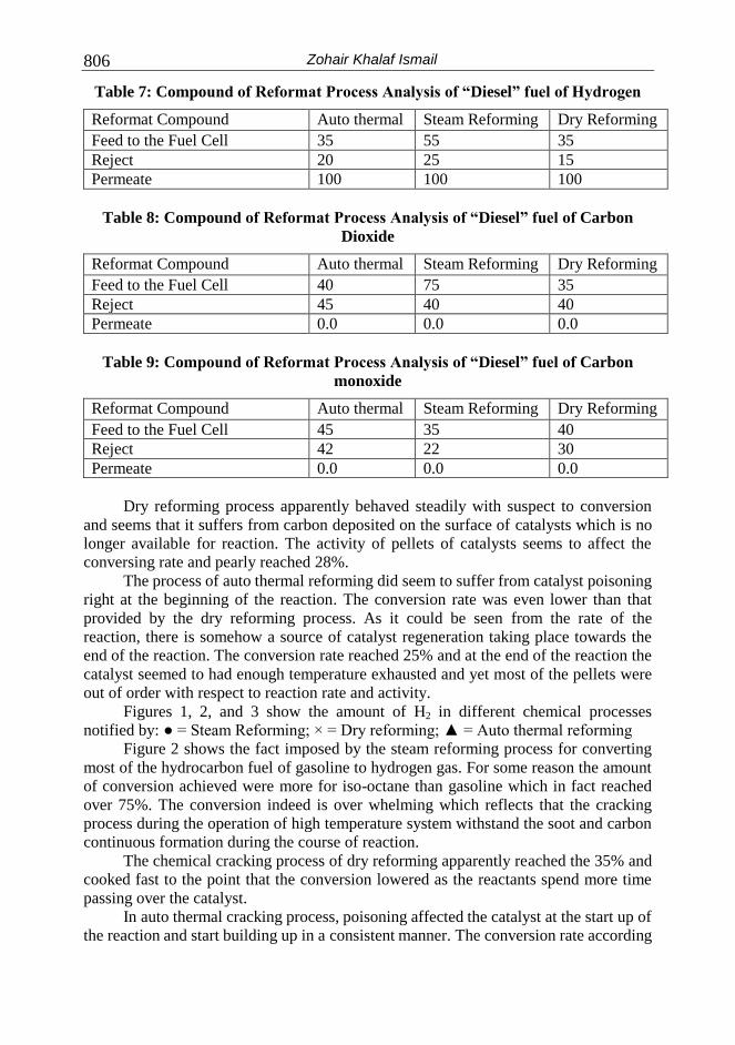
Table 7: Compound of Reformat Process Analysis of “Diesel” fuel of Hydrogen
Reformat Compound Auto thermal Steam Reforming Dry Reforming
Feed to the Fuel Cell 35 55 35
Reject 20 25 15
Permeate 100 100 100
Table 8: Compound of Reformat Process Analysis of “Diesel” fuel of Carbon
Dioxide
Reformat Compound Auto thermal Steam Reforming Dry Reforming
Feed to the Fuel Cell 40 75 35
Reject 45 40 40
Permeate 0.0 0.0 0.0
Table 9: Compound of Reformat Process Analysis of “Diesel” fuel of Carbon
monoxide
Reformat Compound Auto thermal Steam Reforming Dry Reforming
Feed to the Fuel Cell 45 35 40
Reject 42 22 30
Permeate 0.0 0.0 0.0
Dry reforming process apparently behaved steadily with suspect to conversion
and seems that it suffers from carbon deposited on the surface of catalysts which is no
longer available for reaction. The activity of pellets of catalysts seems to affect the
conversing rate and pearly reached 28%.
The process of auto thermal reforming did seem to suffer from catalyst poisoning
right at the beginning of the reaction. The conversion rate was even lower than that
provided by the dry reforming process. As it could be seen from the rate of the
reaction, there is somehow a source of catalyst regeneration taking place towards the
end of the reaction. The conversion rate reached 25% and at the end of the reaction the
catalyst seemed to had enough temperature exhausted and yet most of the pellets were
out of order with respect to reaction rate and activity.
Figures 1, 2, and 3 show the amount of H2 in different chemical processes
notified by: ● = Steam Reforming; × = Dry reforming; ▲ = Auto thermal reforming
Figure 2 shows the fact imposed by the steam reforming process for converting
most of the hydrocarbon fuel of gasoline to hydrogen gas. For some reason the amount
of conversion achieved were more for iso-octane than gasoline which in fact reached
over 75%. The conversion indeed is over whelming which reflects that the cracking
process during the operation of high temperature system withstand the soot and carbon
continuous formation during the course of reaction.
The chemical cracking process of dry reforming apparently reached the 35% and
cooked fast to the point that the conversion lowered as the reactants spend more time
passing over the catalyst.
In auto thermal cracking process, poisoning affected the catalyst at the start up of
the reaction and start building up in a consistent manner. The conversion rate according

COMPARATIVE STUDY OF HYDROCARBON…….
807
to this process got to be around 35% and withstand the temperature effect for over 65
hours. In figure 3, the fact here is some how different than gasoline and iso-octane.
0
10
20
30
40
50
60
70
80
90
100
0 5 10 15 20 25 30 35 40 45 50 55 60 100
Time on stream (hours)
Pro
du
ct
ga
s c
om
po
sit
ion
(%
),d
ry
ba
sis
Figure 1: H2 reformat in process analysis of Gasoline
0
10
20
30
40
50
60
70
80
90
100
0 5 10 15 20 25 30 35 35 45 50 65 100
Time on stream (hours)
Pro
du
ct
ga
s c
om
po
sit
ion
(%
),d
ry
ba
sis
Figure 2: H2 reformat in process analysis of Iso-octane.
The conversion rate for diesel was lower than gasoline and iso-octane. The
catalyst involved only survived 45 hours which is considered to be low when compared
with to other types of fuels.
The process of cracking heavy hydrocarbon type fuels must deal with more
drawbacks and soot formation with respect to conversion which is the factor that most
of the time provides the success of such operation.

Zohair Khalaf Ismail 808
0
10
20
30
40
50
60
70
80
90
100
0 5 10 15 20 25 30 35 35 45 55 65 100
Time on stream (hours)
Pro
du
ct
ga
s c
om
po
sit
ion
(%
),d
ry
ba
sis
Figure 3: H2 reformat in process analysis of Diesel.
Figures 4, 5, and 6 show the amount of CO2 in different chemical processes
notified by: ● = Steam Reforming; × = Dry reforming; ▲ = Auto thermal reforming
The reformation process carried on survives only for 65 hours, whereas that for
dry reforming withstand only for 20 hours. Cracking such type of fuel as seen by the
above figure seems to deal with more carbon formation at the start up of the reaction
than any other fuels. The conversion reached around 55% by the steam reforming
process, whereas did not reach 35% by other cracking processes.
In the above figure, the steam reforming processes seem to have more carbon
dioxide than any other cracking processes producing almost the same amount of gas
for over 30 hrs in constant manner and stayed in the reactor for more than 65 hrs as
well.
The dry reforming process of gasoline type fuel got to have around 30% of
carbon dioxide and survived the reaction up to 20 hours. Whereas the auto thermal
cracking process survived almost 55 hours and contained only 25% of CO2.
The cracking method that took place carried on by hydrocarbon fuels of iso-
octane suffered more of a carbon monoxide formation and a certain amount of carbon
dioxide as well. The driving force for accomplishing better results is to establish a
reaction to convert more of CO to CO2. The disproportion phenomenon of CO2
generates a bad carbon cursor that causes a direct effect and must be accounted to in all
theoretical calculated amounts of H2.
In figure 5 the steam reforming processes has been survived for 20 hours for iso-
octane and contains 35% of carbon dioxide. The dry reforming process contained 25%
and withstands about 35 hours.
The auto thermal reforming process of iso-octane type fuel contained around
20% of carbon dioxide and survived 20 hours.

COMPARATIVE STUDY OF HYDROCARBON…….
809
0
10
20
30
40
50
60
70
80
90
100
0 5 10 15 18 20 30 55 56 60 55 65 100
Space Time (hours)
Pro
du
ct
ga
s c
om
po
sit
ion
of
Ca
rbo
n D
iox
ide
(%),
dry
ba
sis
Figure 4: CO2 reformat in process analysis of Gasoline.
0
10
20
30
40
50
60
70
80
90
100
0 5 10 15 18 19 35 55 56 60 55 65 100
Space Time (hours)
Pro
du
ct
ga
s c
om
po
sit
ion
of
Ca
rbo
n D
iox
ide
(%),
dry
ba
sis
Figure 5: CO2 reformat in process analysis of Iso-octane.
In figure 6 the steam reforming processes seem to have better results one more
time than any other processes (dry or auto thermal). The steam reforming process
survived 55 hours whereas the dry reforming survived heat and soot for only 35 hours.
The amount of carbon monoxide was around 40% for the steam reforming process and
less than 25% in other processes.
Figures 7, 8, and 9 show the amount of CO in different chemical processes
notified by: ● = Steam Reforming; × = Dry reforming; ▲ = Auto thermal reforming
Figure 7 shows the quantity of carbon monoxide formation of the three cracking
reforming processes involved in this study. Steam reforming provides a smaller amount

Zohair Khalaf Ismail 810
of CO than other cracking processes. The few amount of CO provided by the system
indicates that most of the carbon is either migrated the CO to the atomic site of CO2 or
converted through a reaction called disproportion reaction where not all carbons would
be able to be deposited on the surface of the catalyst inside the chamber of the reactive
unit.
0
10
20
30
40
50
60
70
80
90
100
0 5 10 15 18 19 35 45 56 60 55 65 100
Space Time (hours)
Pro
du
ct
ga
s c
om
po
sit
ion
of
Ca
rbo
n D
iox
ide
(%),
dry
ba
sis
Figure 6: CO2 reformat in process analysis of Diesel.
0
5
10
15
20
25
30
35
40
45
50
0 5 10 15 18 19 35 45 56 60 55 65 100
Space Time (hours)
Pro
du
ct
ga
s c
om
po
sit
ion
of
Ca
rbo
n M
on
ox
ide
(%),
dry
ba
sis
Figure 7: CO reformat in process analysis of Gasoline.
Figure 8 proved that the amount of CO evolved seem to be more this time with
steam reforming than dry or auto thermal cracking processes. There is a sort of
regeneration reaction that need to be further studied going through the auto thermal
reforming that we did not experience another processes.

COMPARATIVE STUDY OF HYDROCARBON…….
811
0
5
10
15
20
25
30
35
40
45
50
0 5 10 15 18 19 35 45 56 60 55 65 100
Space Time (hours)
Pro
du
ct
ga
s c
om
po
sit
ion
of
Ca
rbo
n M
on
ox
ide
(%),
dry
ba
sis
Figure 8: CO reformat in process analysis of Iso-octane.
Figure 9 shows that the amount of CO that evolved by the cracking process
system in steam reforming is less than that in auto thermal cracking. The reaction that
converts carbon monoxide to carbon dioxide seems to be more feasible in auto thermal
processes than steam reforming or dry reformation unit system.
0
5
10
15
20
25
30
35
40
45
50
0 5 10 15 18 19 35 45 56 60 55 65 100
Space Time (hours)
Pro
du
ct
ga
s c
om
po
sit
ion
of
Ca
rbo
n M
on
ox
ide
(%),
dry
ba
sis
Figure 9: CO reformat in process analysis of Diesel.

Zohair Khalaf Ismail 812
CONCLUSION
The study is conducted to observe the difference between the three cracking systems
technology. The purpose of the study is however to be able to feed pure hydrogen gas
to the fuel cell unit operation. The study tested three different types of hydrocarbon
fuels that contain different chains of stiff carbons which may affect the soot
phenomenon.
Hydrocarbon type fuels involved in the study are gasoline, iso-octane and diesel
type fuels. In all cases the theoretical analytical calculations involved the amount of
synthesis gases of hydrogen; carbon dioxide and carbon monoxide were taken into
account in order to come up with a sort of reaction to maximize the amount of
hydrogen gas. Also the amount of both synthesis gases of CO and CO2 play a role
since we are yet looking for a methodology to increase the conversion of CO to CO2.
However; among all the three cracking chemical processes the best one of reformatting
hydrocarbon fuels to synthesis gases is the steam reforming process. For all the studied
fuels, the production of H2 is higher and the amount of CO is lower. The catalyst also is
the driving force for good conversion which reflects the fact that there is a possibility
to stay longer in the reaction bed where more conversion expected. Diesel fuel
remains the challenges for its stiffness to extract as much hydrogen as possible and
with little carbon monoxide to ensure that the system is capable to withstand high
temperature elevation as well as pressure imposed by other factors in the reaction
chamber.
FUTURE WORK
We recommend to evaluate different types of catalyst and to evaluate their influence at
different process conditions. Temperatures must be one of the parameters that the
investigation may include as well as the water to carbon ratio.
REFERENCES
1. Zohair K. Ismail, J Auto thermal Theoretical Catalytic Micro-channel Reactor
Calculations for Cracking Hydrocarbon Fuels. Journal of institute of
mathematics and computer sciences, India, vol. 16, June 1st, 2005.
2. Zohair K. Ismail, Autothermal theoretical catalytic micro channel reactor
calculations for cracking hydrocarbon fuels. Journal of institute of mathematics
and computer sciences, India, vol. 16, No.1, 2005.
3. Ahmed, S., M. Krumpelt, R. Kumar, S.H.D. Lee, J.D. Carter, R. Wilkenhoener,
and C.Marshall, “Catalytic Partial Oxidation Reforming of Hydrocarbon Fuels,”
1998 Fuel Cell Seminar Abstracts, Courtesy Associates, Inc., Washington, D.C.,
1998, 242-245.
4. P. Irving, W.L. Allen, Q. Ming, and T. Healey. Novel Catalytic fuel reforming
with advanced membrane technology, Innova Tek, Inc. DOE, proceedings of the
2001.

COMPARATIVE STUDY OF HYDROCARBON…….
813
LITERATURE CITED
1. Richard M. Felder and Ronald W. Rousseau. Elementary Principles of Chemical
Processes, 2nd
edition. Wiley 1986.
2. Godickemeier, M., Sasaki, K. & Gauckler, L. J.in Proc. 4th Int. Symp. on Solid
Oxide Fuel Cells (edsDokiya, M., Yamamoto, O., Tagawa, H & Singhal, S. C.),
Electrochemical Soc., Pennington, 1995.
3. Hori, C. E.et al. Thermal stability of oxygen storage properties in a mixed CeO2-
ZrO2system. Appl. Catal. B 16, 1998.
4. Fung, K-Z., Chen, J., Tanner, C. & Virkar, A. V.in Proc. 4th Int. Symp. On Solid
Oxide Fuel Cells (eds byDokiya, M., Yamamoto, O., Tagawa, H. & Singhal, S.
C.), Electrochemical Soc., Pennington, 1995.
5. Aida, T., Abudala, A., Ihara, M., Komiyama, H. & Yamada, K.in Proc. 4th Int.
Symp. On Solid Oxide Fuel Cells (eds Dokiya, M., Yamamoto, O., Tagawa, H.
& Singhal, S. C.).
6. Sfeir, J., Van herle, J. & McEvoy, A. J.in Proc. 3rd European Solid Oxide Fuel
Cell Forum (ed. Stevens, P.), European Fuel Cell Forum, Switzerland, 1998.
7. Wang, J., Wasmus, S. & Savinell, R. F. Evaluation of ethanol, 1-propanol, and 2-
propanol in a direct oxidation polymer-electrolyte fuel cell. A real-time mass
spectrometry study. J. Electrochem. Soc. 142, 1995.
8. Ren, X., Wilson, M. S. & Gottesfeld, S. High performance direct methanol
polymer electrolyte fuel cells. J. Electrochem. Soc. 143, L12-L14, 1996.
9. Tsai, T. & Barnett, S. A. Effect of mixed-conducting interfacial layers on solid
oxide fuel cell anode performance. J. Electrochem. Soc. 145, 1998.
مقارنة بين أنواع الوفود الهيدروكربونية و إنتاج غازات الهيدروجين وثاني أكسيد الكربون وأول أكسيد الكربون
من ثالثةة ننةعام مةن H2 , CO, CO2تم إجراء هذه الدراسة بغرض التمييز بين مفاعالت إنتاج غازات من المحفزات الكيميائية عااليزع اعكتان عالديزل ( مع استخدام عدد –العقعد هي ) الجازعلين
Molybdenum Carbide, Tungsten Carbide & Zinc Oxide) .)
هةةةي التحعيةةةةل بالبخةةةةار ; نعتةةةم اسةةةةتخدام ثالثةةةةة تةةةري لاميةةةةامالت الكيميائيةةةةة لاح ةةةعل عاةةةة ال يةةةةدرعجي التحعيةةل بالبخةةار هةةي نيقةةل تري ةةة عالتحعيةةل الجةةال عالتحعيةةل ذاتةةي الحةةرارن. عقةةد تبةةين مةةن الدراسةةة نن
إلنتاج اكبر كميه من ال يدرعجين. نما مةن الناحيةة التتبي يةة عاالقت ةادية يمكةن نن تةادج نتةائل هةذه الدراسةة إلة نن إنتةاج غةاز ال يةدرعجين
من ننعام العقعد المختافة عخا ة الديزل يستخدم يي خاليا العقعد .