Comparative study of cycle performance for a two stage intermittent solar refrigerator working with...
7
Pergamon o196-sgo4(~)OOOlS-i Energy Convers.Mgmt Vol. 37, No. I, pp. 87-93, 1996 Copyright © 1995 Elsevier Science Lid Printed in Great Britain. All rights reserved 0196-8904/95 $9.50+ 0.00 COMPARATIVE STUDY OF CYCLE PERFORMANCE FOR A TWO STAGE INTERMITTENT SOLAR REFRIGERATOR WORKING WITH R22-ABSORBENT COMBINATIONS KRISHNENDU DAS and A. MANI Refrigeration and Aireonditioning Laboratory, Department of Mechanical Engineering, Indian Institute of Technology, Madras 600 036, India (Received 4 March 1994; receivedfor publication 8 February 1995) Abstract--An analysis of the thermodynamic cycle for a two stage intermittent solar refrigerator is performed for R22-DM F, R22-NMP and R22-DMETEG. The effects of different parameters, like volume ratio, and high and low pressure stage initial concentrations on cycle performance are studied for these combinations. The comparison of cycle performances between these working fluids helps in selecting the best working fluid combination. Solar refrigerator Modified intermittent system Ozone friendly working fluid Parametric study Best NOMENCLATURE h = Solution enthalpy (kJ/kg) hie = Enthalpy of saturated liquid R22 (kJ/kg) h v = Enthalpy of refrigerant vapour (kJ/kg) hw = Enthalpy of vapour coming from LPG (kJ/kg) h~c = Enthalpy of saturated R22 vapour (kJ/kg) hve = Enthalpy of pure refrigerant vapour at evaporator temperature (kJ/kg) m = Solution mass (kg) m s = Mass of solution (kg) m,~ = Mass of refrigerant entering high pressure stage absorber (kg) mvc = Mass of vapour entering condenser (kg) mve = Mass of refrigerant passing through evaporator (kg) mvg = Total mass of vapour generated (kg) mvgh = Mass of vapoar generated from high pressure stage (kg) mvg j = Mass of vapour generated from low pressure stage (kg) Qa = Total absorber load (k J) Q~ = High pressure stage absorber load (k J) Qal = Low pressure stage absorber load (k J) Qc = Condenser load (k J) Qe = Evaporator load (k J) Qg = Total generator load (k J) Q~ = High pressure stage generator load (k J) Q~ = Low pressure stage generator load (k J) Xs = Mass concentration of liquid solution Xv = Mass concentration of solution vapour Abbreviations COP = Coetiicient of performance DMF = N,N-Dimethyl formamide DMETEG = Dimethylether tetraethylene glycol HPG = High pressure stage generator LPG = Low pressure stage generator NMP = N = Methyl, l-2-pyrolidone R22 = Monochloro difluoro methane INTRODUCTION The refrigerator used for solar assisted systems is the two stage intermittent vapour absorption refrigerator. The working fluids so far used in this system are either NH3-H20 or H20-LiBr. Due 87
-
Upload
krishnendu-das -
Category
Documents
-
view
212 -
download
0
Transcript of Comparative study of cycle performance for a two stage intermittent solar refrigerator working with...

Pergamon o196-sgo4(~)OOOlS-i Energy Convers. Mgmt Vol. 37, No. I, pp. 87-93, 1996
Copyright © 1995 Elsevier Science Lid Printed in Great Britain. All rights reserved
0196-8904/95 $9.50 + 0.00
COMPARATIVE STUDY OF CYCLE PERFORMANCE FOR A TWO STAGE INTERMITTENT SOLAR REFRIGERATOR
WORKING WITH R22-ABSORBENT COMBINATIONS
KRISHNENDU DAS and A. MANI Refrigeration and Aireonditioning Laboratory, Department of Mechanical Engineering, Indian Institute
of Technology, Madras 600 036, India
(Received 4 March 1994; received for publication 8 February 1995)
Abstract--An analysis of the thermodynamic cycle for a two stage intermittent solar refrigerator is performed for R22-DM F, R22-NMP and R22-DMETEG. The effects o f different parameters, like volume ratio, and high and low pressure stage initial concentrations on cycle performance are studied for these combinations. The comparison of cycle performances between these working fluids helps in selecting the best working fluid combination.
Solar refrigerator Modified intermittent system Ozone friendly working fluid
Parametric study Best
N O M E N C L A T U R E
h = Solution enthalpy (kJ/kg) hie = Enthalpy of saturated liquid R22 (kJ/kg) h v = Enthalpy of refrigerant vapour (kJ/kg)
h w = Enthalpy of vapour coming from LPG (kJ/kg) h~c = Enthalpy of saturated R22 vapour (kJ/kg) hve = Enthalpy of pure refrigerant vapour at evaporator temperature (kJ/kg) m = Solution mass (kg) m s = Mass of solution (kg)
m,~ = Mass of refrigerant entering high pressure stage absorber (kg) mvc = Mass of vapour entering condenser (kg) mve = Mass of refrigerant passing through evaporator (kg) mvg = Total mass of vapour generated (kg)
mvgh = Mass of vapoar generated from high pressure stage (kg) mvg j = Mass of vapour generated from low pressure stage (kg)
Qa = Total absorber load (k J) Q~ = High pressure stage absorber load (k J) Qal = Low pressure stage absorber load (k J) Qc = Condenser load (k J) Qe = Evaporator load (k J) Qg = Total generator load (k J)
Q~ = High pressure stage generator load (k J) Q~ = Low pressure stage generator load (k J) X s = Mass concentration of liquid solution Xv = Mass concentration of solution vapour
Abbreviations
COP = Coetiicient of performance DMF = N,N-Dimethyl formamide
DMETEG = Dimethylether tetraethylene glycol HPG = High pressure stage generator LPG = Low pressure stage generator
NMP = N = Methyl, l-2-pyrolidone R22 = Monochloro difluoro methane
INTRODUCTION
The refrigerator used for solar assisted systems is the two stage intermittent vapour absorption refrigerator. The working fluids so far used in this system are either NH3-H20 or H20-LiBr. Due
87

88 DAS and MANI: CYCLE PERFORMANCE OF A SOLAR REFRIGERATOR
to the rectification and toxicity problem of the ammonia-water system and the crystallization and vacuum pressure problem of the LiBr-water at subzero temperatures, these working fluids are substituted by R22-absorbent combinations. R22 is a popular choice as refrigerant for its ozone friendliness (ODP = 0.05). The working fluids used in this paper for the analysis are R22-DMF, R22-NMP and R22-DMETEG. The thermodynamic analysis of the operating cycle is performed with these working fluids in order to study the effects of different parameters on cycle performance, and a comparison between them helps in choosing the best working fluid.
S Y S T E M D E S C R I P T I O N
Figure 1 shows the schematic diagram of the modified two stage intermittent solar refrigerator used for the analysis. The system works on an intermittent basis. The solution tanks T1 and T2 are connected to the high pressure stage and T3, T4 are connected to the low pressure stage. When tanks T1 and T3 are connected to their respective generators, tanks T2 and T4 are connected to their respective absorbers. The solutions in the tanks connected to the generators get heated by the thermosyphon effect. Once the solution in tank T1 reaches its generation starting point temperature, pure R22 vapour comes from it and gets condensed at condenser C. The condensate then gets stored at condensate tank CT1. Valves 1, 2 and 9 are kept open and valves 3-6 are kept closed at the high pressure stage for this purpose. At the same time, T3 starts generating refrigerant vapour which then gets absorbed at the high pressure stage absorber. Valves 21, 22, 26 are kept open for this purpose. This process helps in compensating for the deficiency of solution concentration, created during the previous cycle operation, in tank T2. Valves 7 and 8 at the high pressure stage are kept open for this purpose. When the condensate is getting stored at condensate tank CTI, the already existing refrigerant liquid from the other tank, CT2, expands through the expansion device and enters the evaporator. At the evaporator, the refrigerant takes the cooling load and gets vapourized again. This vapour then gets absorbed at the low pressure stage absorber. This process helps in compensating for the deficiency of solution concentration in tank T4. Valves
-ICoo oser
)9 ~o(
IPressurel igenero.tor[ :~pressure I ~ _ _- . sorb,r I=
F
I
~11 13~)
112 141~p / ~ = L ~ x ~ Evaporator"
a e v l c e
26 "
:.pressure ~bsorber != QQ,I ~,,¢'~
Fig. 1. Schematic diagram of modified two stage intermittent solar refrigerator.

DAS and MANI: CYCLE PERFORMANCE OF A SOLAR REFRIGERATOR 89
17 and 18 are kept open and 23 and 24 are kept closed for this purpose. This completes the cycle. Once the generation from T1 and T3 are completed, those two tanks are disconnected from their generators and are connected to their respective absorbers. Simultaneously, the solution tanks T2 and T4 are connected to their respective generators. Thus, the next cycle starts. This cycling process goes on until the time sunshine is available. The continuous refrigeration effect is obtained from the system by using condensate tanks CTI and CT2 alternatively, with a sufficient refrigerant storage facility.
CYCLE DIAGRAM
Figure 2 shows the thermodynamic cycle of a two stage intermittent solar refrigerator[l, 2]. Processes 1-2-3-4 and 11-22-33-44 are taking place at the high and low pressure stages, respectively. The processes are as follows:
1-2--sensible heating at HPG 2-3--heating with generation at HPG
11-22--sensible heating at LPG 22-33--heating with generation at LPG.
3-4 and 33-44 represents natural cooling of the generators to condenser temperature.
Process point 5 represents the state of the refrigerant at the condensate tank. 5-6 is expansion at the expansion device, and as the process goes on, the point 6 shifts to state
point 7. The temperature corresponding to state point 7 is the minimum evaporator temperature that can be achieved from the system.
THERMODYNAMIC ANALYSIS OF CYCLE
The thermodynamic analysis of the cycle is performed based on enthalpy data available for the working fluids. The property data required for the analysis are generated [1] from the property data
P
5 2
t te t a - t c =to tgh tgl
Fig. 2. Thermodynamic cycle diagram of modified two stage intermittent solar refrigerator.
90 DAS and MANI: CYCLE PERFORMANCE OF A SOLAR REFRIGERATOR
available for pure refrigerant [3] and pure absorbents [4]. The COP of the system is found as follows:
The heat required in the generator is calculated by writing the energy balance equation to the generator. This is given for the high pressure stage as:
Qgh = m3h3 - - mi hi + dm~ghhv • (1)
Similarly, for the low pressure stage, the generator load is given as:
Qgl = m33h33 - - roll hl l Jr" dmvglhv. (2) 3
So, the net heat transfer to the generators is found by adding the loads of the two generators, and it is given as:
Qg = Qgl, + Qg, . ( 3 )
The total amount of vapour generated at the high and low pressure stages during processes 2-3 and 22-33 are found as:
mvg h = [dxsm/(1 -- Xs)]HpO (4)
f233 mvg I = [dxsm 1(1 - Xs)]L~. (5) 2
Here, the vapour coming from the generator can be considered as having 100% concentration. The amount of refrigerant (R22) condensed at the condenser is given as:
mvc = rnvg~. (6)
The amount of refrigerant entering the evaporator is mvc. There, it takes the cooling load and gets vapourized. So, the evaporator load is calculated as:
Q~ = Sdmw(hv< - h,¢). ( 7 )
Here, mve is equal to m~c. The theoretical coefficient of performance of the cycle is evaluated as the ratio of the refrigeration
effect to the total heat required in the two generators. This is given as:
COP = a e / a g . (8)
0,140
0 1 2 0 ~ . _ ~ . ~ -"Jr---% " - . t~
, i j j 0 ~ VR = 1.0 (-~ 0.060 . . . . . . t .2
1.4- qooo_o R 2 2 - N M P + + + + + R 2 2 - D M F
0.040 * * * * * R22-DMETEG
0.020 Xh=0"65 X~=0.45 tc=35°C t , = - 5 ° C
0.000 ~ ,
60 . . . . . . . . 7'0 . . . . . . . . . 8~0 . . . . . . . . . 9'0 . . . . . . i O0
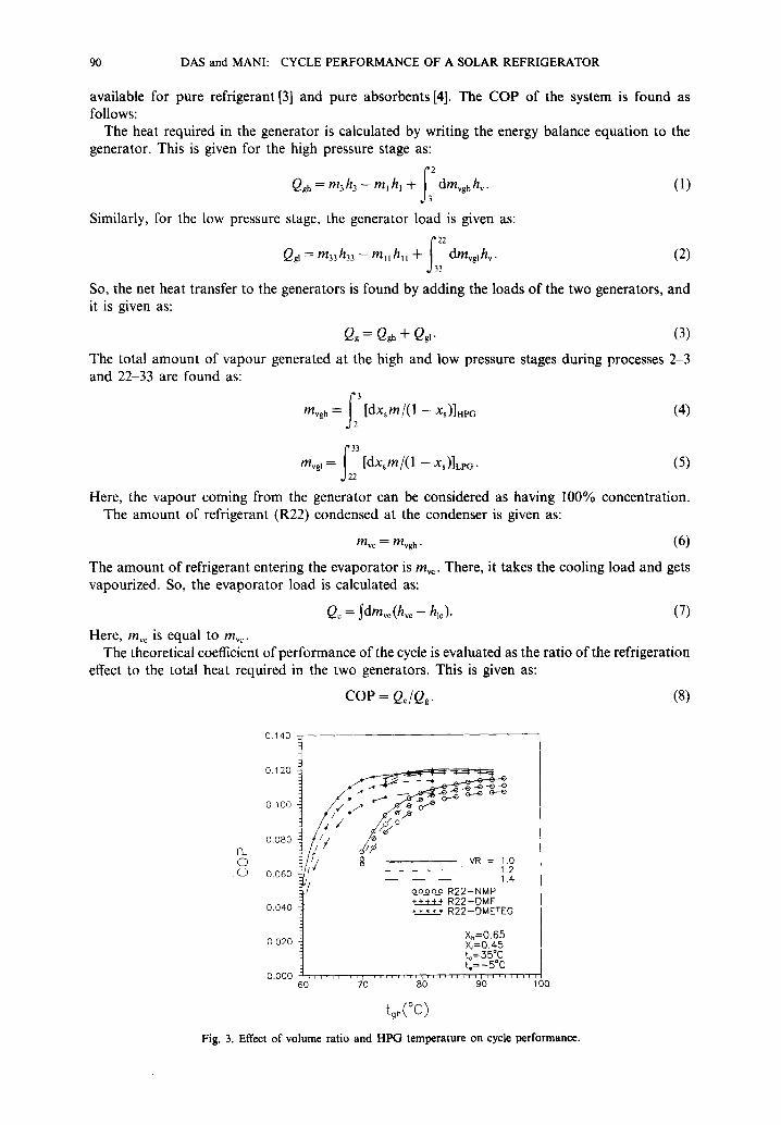
tgh(°c) Fig. 3. Effect of volume ratio and HPG temperature on cycle performance.

DAS and MANI" CYCLE PERFORMANCE OF A SOLAR REFRIGERATOR 91
(.D
140 -
120
I O0
80
60
4-0
20 60
VR = 1.0 . . . . 1.2
1.4
d Xh=0.65 X,=0.45 t~=35°c t , = - 5 ° c
oo_oo~ R22-NMP + + + +~+ R22-DMF ***** R22-DMETEG
70 80 90 1 O0
t g h ( ° C )
Fig. 4. Effect of volume ratio and HPG temperature on LPG temperature.
R E S U L T S A N D D I S C U S S I O N
The thermodynamic analysis of the operating cycle is performed by varying different parameters, like volume ratio and high and low pressure stage initial concentrations. The optimum initial solution concentrations at the high and low pressure stages are taken for the analysis [5]. The effects of these parameters on cycle performance for the working fluids are studied. A comparative study among these working fluids helps in finding the best R22 absorbent combination.
Figure 3 shows the variation of system COP with respect to HPG temperature at different volume ratios. The figure shows that, at a certain volume ratio, the COP of the system increases with an increase in HPG temperature, and at any HPG temperature, the COP of the system increases with a decrease in volume ratio. This is because, at the same operating condition, the mass of vapour generation increases with an increase in HPG temperature, which results in more refrigeration effect and more system COP. The figure also shows that the operating HPG temperature range for R22-DMETEG is comparatively lower than the other two combinations. It is clear from the figure that at all volume ratios and generator temperatures, the R22-DMF combination gives better performance than the other two.
0.130
S o o o--o--~
o 0
0.090
0_ 0 / ~ / g , / ~ 0 0.070 /
X~=0.45 /
/ tc=35°C % = - 5°C
0.050 t / VR= I .3
ooooo R22-DMF Xh=0.65 ~ t ~ a R22-NMP
- - - 0.60 * * * * * R22-DMETEG 0.030 . . . . . . .
60 . . . . . . . . . 7~0 ' '810 . . . . . . . . . 9~0 . . . . . . . . i00
tgh ( ° C )
Fig. 5. Effect of HPG initial concentration and HPG temperature on system performance.

92 DAS and MANI: CYCLE PERFORMANCE OF A SOLAR REFRIGERATOR
11o
1 oo
90
8oi o
7oi
60
50 i
X j = 0 , 4 5 t c=35°C
X.=0.65 -~ . . . . 0.60 ~r
'~" ooooo R22-DMF ~, ~.a ~,,~ R22-NMP * * * * * R22-DMETEG
4Q , f ; l l l l l l l l l t l l l l l l l , l l l l l l l , l l , l l l l l l l
60 70 80 90 100
tgh ( ° C )
Fig . 6. Effect of HPG initial concentration and HPG temperature on LPG temperature.
Figure 4 shows the variation of low pressure stage generator temperature with respect to HPG temperature for different volume ratios. The figure shows that, at a certain volume ratio, the LPG temperature for the working fluids are close to each other. It also shows that the temperature matching between the high and low pressure stages occurs at a volume ratio of 1.3 for all the combinations. This temperature matching is important because, in practice, it is easy to achieve this condition by using a flat plate collector.
The effect of the high pressure stage initial concentration on system performance is shown in Fig. 5. The figure shows that the COP of the system increases with an increase in the HPG initial concentration. The figure also shows that, at all HPG initial concentrations, the R22-DMG gives better performance than the other two working fluids. So, this figure supports the supremacy of R22-DMF.
As per the above description, we can get better performance from the system if the HPG initial concentration is increased. The maximum concentration that can be allowed is restricted by the temperature matching consideration between the high and low pressure stages. The variation of LPG temperature with respect to HPG temperature at different HPG initial concentrations is shown in Fig. 6. The figure also shows that, at a certain volume ratio, the LPG temperatures required are close to each other for all the combinations.
0 . 1 4 0
0._ 0
0 . 1 0 0
0.060
0.020
• / , ~ - - X , = 0 . 4 5 . . . . 0.40
/ / / x.=o 65
/ ' t ° = - 5 C !/ VR= 1.5
o o o o o R22-DMF A~,aa~ R22-NMP * * * * * R22-DMETEG
1 1 1 1 L i T i i L i l l l r , l l , l l l l ; l l l l ~ l l l i [ l l l r l 60 70 80 90 100
tgh (°C)
Fig. 7. Effect of LPG initial concentration and HPG temperature on system performance.

DAS and MANI: CYCLE PERFORMANCE OF A SOLAR REFRIGERATOR 93
5~
- 5 / / o
0 - 1 0 / / ~ /
~" J "" X~=0.50 - 2 0 - 0.45
o o o o o R22-DMF ~ a ~,~,z, R22-NMP
- 2 5 ***7* R22-DMETEG
For oil volues of t~. end Xh - ~ 0 i , l l , l p l l ' r l l l l l l l ~ l l l l l l r ' l l l l l r l l l ~ l l l r l l ~ l l V
25 30 35 40 45 50
(°c) Fig. 8. Effect of LPG initial concentration and condenser temperature on evaporator temperature.
The effect of the low pressure stage initial concentration on cycle performance is shown in Fig. 7. The figure shows that, as the LPG initial concentration increases, the COP of the system also increases. It also shows that, at all LPG concentrations, the R22-DMF system gives better performance among the working fluids.
The system gives better performance with an increase in the LPG initial concentration. The maximum concentration that can be allowed is restricted by the evaporator temperature we want to achieve from the system. Figure 8 shows the variation of evaporator temperature with respect to condenser temperature at different low pressure stage initial concentrations. It shows that, at a certain condenser temperature, the minimum evaporator temperature that can be achieved from the system increases with an increase in LPG initial concentration. The initial concentration of 0.45 is selected [5] for all the combinations because, at this concentration, the system can give subzero evaporator temperature at the entire range of condenser temperatures.
C O N C L U S I O N
The theoretical analysis of the thermodynamic cycle, based on enthalpy data, helps us in estimating the performance of the refrigeration system. The parametric study, based on the cycle analysis, shows the effects of different parameters on cycle performance. A comparative study of the cycle performances for the different working fluids helps in finding the best working fluid, and it comes out to be R22-DMF.
R E F E R E N C E S
1. A. Mani, Two stage intermittent ammonia-water solar refrigerator operating with flat plate collector. Ph.D. thesis, I.I.T Madras (1986).
2. A. Mani and A. Venkatesh, Energy Convers. Mgmt 26, 271 (1986). 3. ASHRAE, ASHRAE Handbook of Fundamentals. ASHRAE, U.S.A. (1981). 4. R. W, Gallant. Hydrocarbon Processing (1969, 1970). 5. Krishnendu Das, Analysis of two stage intermittent solar refrigerator working with ozone friendly working fluid.
M. Tech. thesis, I.I.T. Madras (1994).
B I B L I O G R A P H Y
S. C. Bhaduri and H. K. Varma, Int. J. Refrig. 9, 362 (1986). M. Fatouh and S. Srinivasamurthy, J. Renewable Energy p. 65 (1992). G. Grossman, K. Gommed and D. Gadoth, ASHRAE Trans. 93 2, 2389 (1987). R. A. Macriss, ASHRAE Conference, Dallas, pp. 975-988 (1976).