Comparative Study for Improving the Thermal and Fluid Flow Performance of Micro Channel Fin...
10
American Journal of Engineering Research (AJER) 2015 American Journal of Engineering Research (AJER) e-ISSN: 2320-0847 p-ISSN : 2320-0936 Volume-4, Issue-7, pp-73-82 www.ajer.org Research Paper Open Access www.ajer.org Page 73 Comparative Study for Improving the Thermal and Fluid Flow Performance of Micro Channel Fin Geometries Using Numerical Simulation S.Subramanian 1 , K.S.Sridhar 2 , C.K.Umesh 3 1 Microwavetube Research & Development center, Jalahalli, Bangalore, 560 013, India 2 PES Institute of Technology, 100 feet Ring Road, BSK III Stage, Bangalore, 560 085,India 3 University Visvesvaraya College of Engineering, KR Circle, Bangalore, 560 001, India ABSTRACT : There is a continuous quest for improving the performance of micro channels for handling the increased dissipation of heat from electronics circuits. The Oblique fin micro channels are attractive as they perform better than plate fin & pin fin configurations. There are scopes for further improvements in oblique fin micro channels. Hence this work is about the investigation for the performance enhancement by modifying the oblique fin geometry. Seven variants of micro channel geometries have been explored using three dimensional numerical simulations. The variants are plate fin, in-line pin fin, staggered pin fin, oblique fin, oblique fin with two slit angles, oblique with nozzle type slit and improved oblique fin. The simulation results are validated using the published data. To ensure a common reference for comparison, hydraulic diameter, inlet flow conditions, heat loads and the boundary conditions are kept identical across all the geometries. The results of simulation are compared for the thermal & fluid flow performances. Heat transfer correlations have been developed using the simulation data. The proposed modification is found to enhance the performance significantly. Keywords - Micro channels, heat sinks, Electronics cooling, Single phase cooling, Forced convection cooling, CFD simulation I. INTRODUCTION The operational effectiveness of electronic circuits depends mainly on the thermal handling capability of their cooling system. Most often, it is required to achieve higher heat transfer coefficient in compact volume. Hence micro channel heat sinks are prospective options which can handle enhanced levels of heat flux due to its higher surface area to volume ratio. Micro channel research has been under active consideration since the work of Tuckerman and Pease [1]. Li and Peterson [2] have optimized the plate fin micro channel geometries for the constant pumping power criterion. They achieved 20% lower thermal resistance than Tuckerman & Pease. Lee and Garimella [3] studied the plate fin micro channels by varying the aspect ratios. They proposed a generalized correlation for predicting Nusselt number. There was uncertainty over the applicability of conventional heat transfer theory for micro channel system. Hence the liquid flow in the micro channels were investigated both experimentally & numerically [4]. They concluded that the conventional theory is applicable for predicting the flow behavior. Lee P S et al. [5] proved that it is possible to increase the local heat transfer coefficient by creating a small recess at the cover lid near the hot spot region. They found that the small recess caused the breakage and re-initialization of boundary layer resulting in the increased heat transfer coefficient. This concept was pursued further by many researchers. As an extension of this Lee, Y. J. et al., [6] have experimentally studied the heat transfer from silicon chips using oblique fins. They have proposed to vary the oblique fin pitch for the mitigating local hot spots in silicon chips. Xu et al. [7-8] have carried out experimental and numerical studies to enhance heat transfer rate by using the concept of boundary layer redevelopment. They found that the interruption in the fins leads to boundary layer redevelopment thus increasing the heat transfer coefficient. These interruptions induced pressure recovery at the exit & pressure loss at the entrance. Qu [9] has reported that the pin fin heat sinks are thermally efficient than the conventional plate fin micro channels of the same hydraulic diameter but with a penalty of higher pressure drop. The performance of the Pin fin heat sink was reported to degrade at lower flow rates [10]. Liu et al. [11] have conducted experiments on square pin fins
-
Upload
ajer-journal -
Category
Documents
-
view
1 -
download
0
description
There is a continuous quest for improving the performance of micro channels for handling the increased dissipation of heat from electronics circuits. The Oblique fin micro channels are attractive as they perform better than plate fin & pin fin configurations. There are scopes for further improvements in oblique fin micro channels. Hence this work is about the investigation for the performance enhancement by modifying the oblique fin geometry. Seven variants of micro channel geometries have been explored using three dimensional numerical simulations. The variants are plate fin, in-line pin fin, staggered pin fin, oblique fin, oblique fin with two slit angles, oblique with nozzle type slit and improved oblique fin. The simulation results are validated using the published data. To ensure a common reference for comparison, hydraulic diameter, inlet flow conditions, heat loads and the boundary conditions are kept identical across all the geometries. The results of simulation are compared for the thermal & fluid flow performances. Heat transfer correlations have been developed using the simulation data. The proposed modification is found to enhance the performance significantly.
Transcript of Comparative Study for Improving the Thermal and Fluid Flow Performance of Micro Channel Fin...
American Journal of Engineering Research (AJER) 2015
American Journal of Engineering Research (AJER)
e-ISSN: 2320-0847 p-ISSN : 2320-0936
Volume-4, Issue-7, pp-73-82
www.ajer.org Research Paper Open Access
w w w . a j e r . o r g
Page 73
Comparative Study for Improving the Thermal and Fluid Flow
Performance of Micro Channel Fin Geometries Using Numerical
Simulation
S.Subramanian
1, K.S.Sridhar
2, C.K.Umesh
3
1Microwavetube Research & Development center, Jalahalli, Bangalore, 560 013, India
2PES Institute of Technology, 100 feet Ring Road, BSK III Stage, Bangalore, 560 085,India 3University Visvesvaraya College of Engineering, KR Circle, Bangalore, 560 001, India
ABSTRACT : There is a continuous quest for improving the performance of micro channels for handling the
increased dissipation of heat from electronics circuits. The Oblique fin micro channels are attractive as they
perform better than plate fin & pin fin configurations. There are scopes for further improvements in oblique fin
micro channels. Hence this work is about the investigation for the performance enhancement by modifying the
oblique fin geometry. Seven variants of micro channel geometries have been explored using three dimensional
numerical simulations. The variants are plate fin, in-line pin fin, staggered pin fin, oblique fin, oblique fin with
two slit angles, oblique with nozzle type slit and improved oblique fin. The simulation results are validated using
the published data. To ensure a common reference for comparison, hydraulic diameter, inlet flow conditions,
heat loads and the boundary conditions are kept identical across all the geometries. The results of simulation
are compared for the thermal & fluid flow performances. Heat transfer correlations have been developed using
the simulation data. The proposed modification is found to enhance the performance significantly.
Keywords - Micro channels, heat sinks, Electronics cooling, Single phase cooling, Forced convection cooling,
CFD simulation
I. INTRODUCTION The operational effectiveness of electronic circuits depends mainly on the thermal handling capability
of their cooling system. Most often, it is required to achieve higher heat transfer coefficient in compact volume.
Hence micro channel heat sinks are prospective options which can handle enhanced levels of heat flux due to its
higher surface area to volume ratio. Micro channel research has been under active consideration since the work
of Tuckerman and Pease [1]. Li and Peterson [2] have optimized the plate fin micro channel geometries for the
constant pumping power criterion. They achieved 20% lower thermal resistance than Tuckerman & Pease. Lee
and Garimella [3] studied the plate fin micro channels by varying the aspect ratios. They proposed a generalized
correlation for predicting Nusselt number. There was uncertainty over the applicability of conventional heat
transfer theory for micro channel system. Hence the liquid flow in the micro channels were investigated both
experimentally & numerically [4]. They concluded that the conventional theory is applicable for predicting the
flow behavior.
Lee P S et al. [5] proved that it is possible to increase the local heat transfer coefficient by creating a
small recess at the cover lid near the hot spot region. They found that the small recess caused the breakage and
re-initialization of boundary layer resulting in the increased heat transfer coefficient. This concept was pursued
further by many researchers. As an extension of this Lee, Y. J. et al., [6] have experimentally studied the heat
transfer from silicon chips using oblique fins. They have proposed to vary the oblique fin pitch for the
mitigating local hot spots in silicon chips. Xu et al. [7-8] have carried out experimental and numerical studies to
enhance heat transfer rate by using the concept of boundary layer redevelopment. They found that the
interruption in the fins leads to boundary layer redevelopment thus increasing the heat transfer coefficient.
These interruptions induced pressure recovery at the exit & pressure loss at the entrance. Qu [9] has reported
that the pin fin heat sinks are thermally efficient than the conventional plate fin micro channels of the same
hydraulic diameter but with a penalty of higher pressure drop. The performance of the Pin fin heat sink was
reported to degrade at lower flow rates [10]. Liu et al. [11] have conducted experiments on square pin fins

American Journal of Engineering Research (AJER) 2015
w w w . a j e r . o r g
Page 74
keeping the diagonal of the fin aligned to the flow direction. They have developed heat transfer correlations
from the experimental data. However it is observed that the numerical simulations have been extensively used
by many researchers to predict the performance of micro channel heat sinks. Rubio-Jimenez et al. [12] used
numerical analysis to propose the concept of variable fin density for maintaining more uniform temperature of
the IC chip junction. They reported to have achieved an overall temperature gradient lesser than 2oC/mm by
varying the pitch. Fan et al. [13] have numerically simulated the performance of oblique fins on the cylindrical
surfaces. The results of simulation were compared using a performance index. Lee Y J et al. [14-16] have
studied the performance of oblique fin micro channels both experimentally & numerically. They were able to
study the thermal & flow behavior inside the channel by carrying out detailed numerically simulations which are
not otherwise possible by experimentation. Danish et al. [17] have carried out a comparative study using
numerical simulation for optimizing the parameters of rectangular & oblique fin micro channel heat sinks. The
Oblique fin micro channel is reported to enhance the thermal performance with a reasonable pressure drop when
compared with pin fin & plate fin micro channels. This shows that there are scopes for the improvement of
performance of the oblique fin micro channel geometry using the numerical simulation.
The present study consists of two parts. In the first part, the laminar flow through plate fin and oblique
finned micro channel heat sinks are simulated. The results are validated using the published experimental data.
In the second part, seven different micro channel fin geometries are investigated for performance enhancement
using numerical simulation while imposing certain common criteria. Theoretical heat transfer correlations are
developed using simulation data. The results are compared on the basis of performance index.
II. MICRO CHANNEL HEAT SINK DETAILS The micro channel geometry consists of inlet, repetitive fluid passages & outlet. Seven micro channel
fin geometries have been considered for simulation studies. To ensure a reasonable basis for comparison, some
of the dimensional parameters such as the hydraulic diameter, inlet flow conditions, heat load and boundary
conditions are held common across all the geometries. The details of the common parameters are shown in
Table1. The specific dimensional details pertaining to six of seven geometries are presented in Table 2. The
rectangular plate fin micro channel is considered as the seventh geometry. Other than the pin fins & staggered
pin fins, three different modifications are proposed for the oblique fin micro channels. In the first type the angle
of the secondary flow passage is modified to have two angles for the smooth injection fluid in the main channel.
This modification is termed as the oblique fin with two angles. In the second type the secondary flow passage is
modified like a convergent nozzle. This is termed as nozzle type micro channels. In the third type fluid entering
the secondary flow passage is given an entry and exit angle for smoother diversion & injection of secondary
flow with the main flow. This modification is termed as the improved oblique fin micro channels.
III. COMPUTATIONAL DOMAIN & BOUNDARY CONDITIONS The micro channel heat sinks have periodically repeating fin and channel pairs. This periodic nature is
exploited in order to reduce the computational load. Hence only one pair of a fin and a channel has been chosen
as the computational domain. The typical computational domains for the plate fin and the oblique fin micro
channels are indicated as the dashed line in Fig 1 and Fig 2. The governing equations relevant to the present
computational domain are continuity equations, Navier-Stroke equations and the energy equations in their
incompressible form. These equations are not reproduced here as they are well known. A commercially
available computational fluid dynamics software ANSYS CFX v.14.5 [19] has been employed for the numerical
simulation which has the capability to solve the above equations using finite volume techniques.
Table 1 Common parameters of the micro channels heat sinks
Feature Details
Width of main channel in micrometers 500
Depth of channel in micrometers 1500
Width of fin in micrometers 500
Size of heat sink in mm X mm 25 X 12.5
Aspect ratio 3
Single fin length in mm 25
Heat sink material Copper
Coolant fluid Water
Heat flux in W/cm2 65

American Journal of Engineering Research (AJER) 2015
w w w . a j e r . o r g
Page 75
Table 2 Micro channel fin geometries with specific dimensional details
Plan view of the micro channels fin geometries. All dimensions are in mm
1.In Line Pin fin 2.Staggered Pin fin
3.Oblique with Two Angle 4.Nozzle type
5.Oblique fin 6.Improved Oblique fin
Fully developed velocity profile is assigned to the inlet. Periodic boundary condition is assigned to the sides. A
uniform heat flux of 65 W/cm2 is applied to the heat sink surface at the bottom. The top of the micro channel
heat sink is considered to be bonded with adiabatic cover. Pressure boundary condition is assigned to the outlet,
where the flow reaches atmospheric pressure. The approach velocity of the fluid is varied from 0.4 m/s to 1.2
m/s. The Reynolds number ranged from 391 to 1130. The temperature dependent materials properties of water
[16] have been used for the simulation with the help of CEL expressions in the ANSYS CFX[19].
Fig. 1 Plan View of Plate fin Micro channels with dimensions in mm

American Journal of Engineering Research (AJER) 2015
w w w . a j e r . o r g
Page 76
Fig. 2 Plan view of Oblique fin Micro Channels with dimensions in mm
IV. GRID INDEPENDENCY CHECKING To ensure grid independent results the model has been meshed at four different grid levels consisting of
676982, 1599592, 23277930 and 4257452 elements. All solid to fluid interfaces have been inflated to a
thickness of 100 micrometers with 8 layers. The Face spacing of 50 micrometers to 20 micrometers has been
applied to fluid region for better resolution. High resolution scheme is selected as solver option. Double
precision has been activated for improving the accuracy. The convergence criterion of 10-6
is set for residues.
Nusselt numbers are found to be in close proximity of to each other except the mesh of 676982. The average
Nusslets number varied by 1.3 % from the first to second mesh level and only by 0.8 % for the second to third
meshes level. The fourth mesh level varied by 0.15% from the third level. Hence the mesh level of 2327790 has
been used. In the similar manner grid dependency check was carried out for each type of simulation.
V. VALIDATION The plate fin micro channel and the oblique fin micro channel have been selected for the validation
purpose. The geometric details are chosen in the similar lines of the work carried out by Y.J.Lee et al [16]
which is considered as the reference data for validation. The dimensional details are shown in Table 3. The
computational fluid dynamic analysis was carried out using ANSYS CFX by varying the inlet velocity. The heat
load of 65 W/cm2 was applied. Figure 3 presents the variation of Nusselt number with Reynold number. It is
observed that the Nusselt number calculated using ANSYS CFX matches closely with that of published
experimental as well as Fluent data for both plate fin and oblique fin micro channels.. The simulated results of
the present study matched closely with that of Fluent results[16] and the experimental data [16]. Hence the
simulation procedure is validated and the same is adopted for the rest of the analysis.
Table 3 Dimensional details used for validation
Parameter Plate fin Oblique fin
Size of heat sink 25mm X25 mm 25mm X 25mm
Main channel width (micrometers) 547 micron 539
Fin width (micrometers) 458 465
Channel depth (micrometers) 1482 micron 1487
Oblique channel width (micrometers) - 298
Oblique angle (degrees) - 27
Oblique fin pitch (micrometers) - 1995
Oblique fin length (micrometers) - 1331
Hydraulic diameter (micrometers) 799 792
Heat sink material Copper Copper
Coolant fluid Water Water

American Journal of Engineering Research (AJER) 2015
w w w . a j e r . o r g
Page 77
VI. RESULTS AND DISCUSSIONS The effect of inlet flow velocity over the pressure drop is presented in two different plots for the sake
clarity which are shown as Fig 4 & Fig 5. The effect of velocity on the pressure drop incurred by all the micro
channel geometries under consideration excluding staggered pin fin configuration is presented as Fig 5. It is
seen that the pressure drop increases with respect to the inlet flow velocities for all the micro channel
geometries. The pressure drop of the plate fin micro channel is the least of all. The pressure drop of the nozzle
type micro channel is the highest as the main channel flow is interrupted by accelerated fluid from the secondary
channel. Whereas the pressure drop of the improved micro channel is the second lowest and is lower than the
oblique micro channel due to the presence of entry exit angles in the secondary flow passage. The pressure drop
of in line pin fin & Oblique with two angles is intermediate between oblique & improved oblique fin. The
comparison of fluid flow performance of all the micro channel geometries with respect to staggered pin fin is
presented in Fig 5. The pressure drop of staggered pin fin is found to be around 4 to 8 folds higher that of the
other types.

American Journal of Engineering Research (AJER) 2015
w w w . a j e r . o r g
Page 78
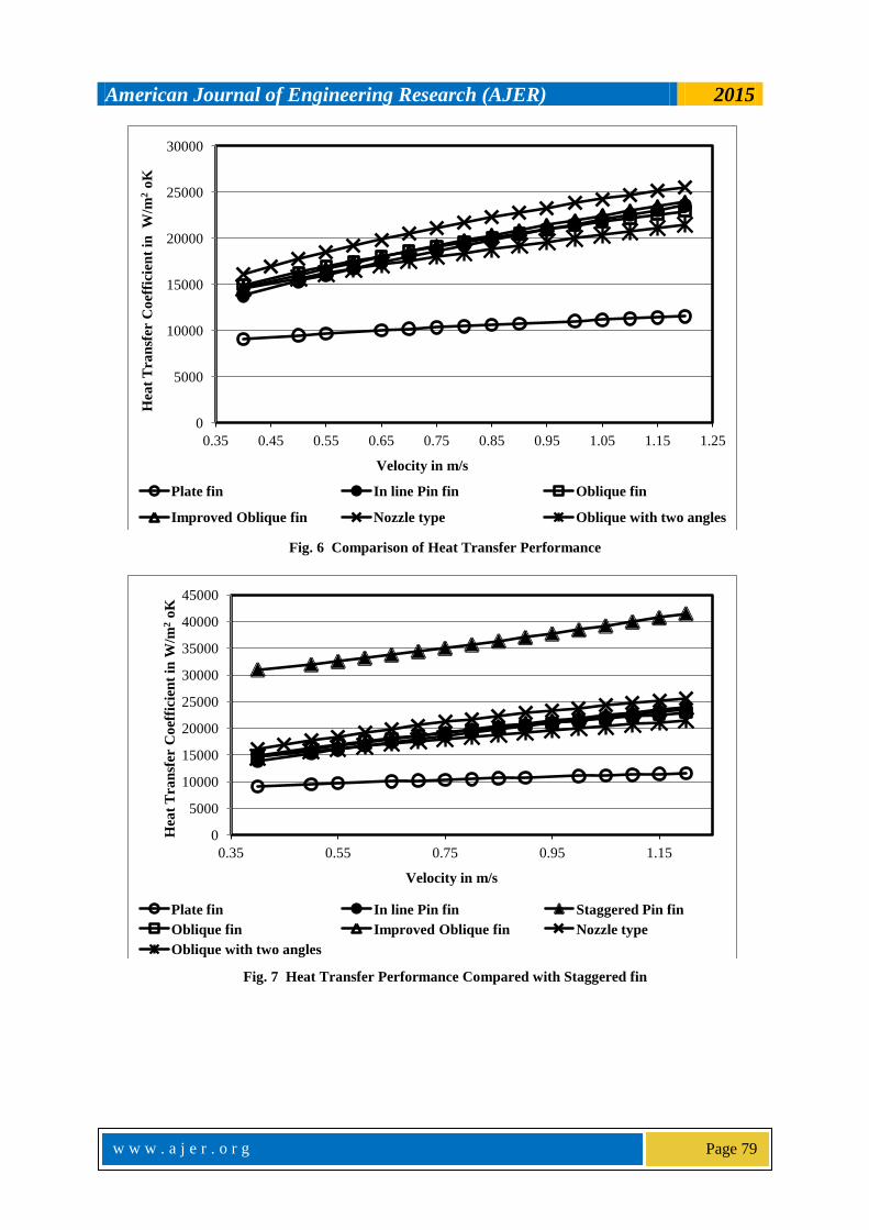
The effect of inlet flow velocity over the heat transfer coefficient is presented in two graphs which are
illustrated as Fig 6 & Fig 7 for the sake of clarity. Figure 7 depicts thermal performance of all the micro
channels except staggered pin fin micro channel. The boundary layer breakage & redevelopment concept is used
by all types of micro channels except the plate fin. Since the boundary layer grows steadily, the heat transfer
coefficient of plate fin is the lowest for the same sets of boundary conditions. The nozzle type micro channel is
found to have higher heat transfer coefficient for the entire range of inlet velocities. The performance of inline
pin fin & improved oblique fin is found to be nearly equal. The performance of the oblique fin & oblique fin
with two angles are found to be lesser than that of the improved oblique fin. Figure 8 compares the performance
of staggered pin fin with that of all other geometries. It is observed that the staggered pin performs better.
Fig. 5 Pressure drop Compared with Staggered Pin fin
It is important to verify the thermal performance considering the available the wetted surface of the micro
channel fin geometries. The heat transfer coefficient is directly proportional to the available heat transfer area &
velocity of flow. The comparison of the wetted surface area is presented in Fig 8. The plate fin geometry has the
lowest wetted surface resulting in the lower thermal performance. The pin fin geometries and the oblique fin
geometry found to have higher wetted surface area leading to higher thermal performance than the plate fin
geometry.
4.1 Discussion on the Performance improved Oblique fin micro channel
The wetted surface area of the improved oblique fin is lesser than inline pin fin & oblique fin geometries.
But the thermal performance of improved oblique fin is found to be closer to that of inline pin fin and oblique
fin geometries. The wetted surface area of the improved oblique fin and nozzle type micro channel is lesser than
oblique fins but the thermal performance is better than oblique fins due to the accelerated secondary flow.
The flow impinges the corner of the oblique fin encountering a shock which will results in early separation
from the fin surface . The wetted surface will not be effectively utilized in the oblique channel. The performance
improvement of improved oblique fin can be attributed to smoother branching of secondary flow. The flow gets
modulated without encountering any shock. This delays the flow separation on the trailing end of the oblique fin
leading to the effective utilization of the wetted surface.
0
2000
4000
6000
8000
10000
12000
14000
16000
18000
0.35 0.45 0.55 0.65 0.75 0.85 0.95 1.05 1.15 1.25
Pre
ssu
re D
rop
in
Pa
sca
ls
Velocity in m/s
Plate fin
In line Pin fin
Staggered Pin fin
Oblique fin
Improved Oblique fin
Nozzle type
Oblique with two angles
American Journal of Engineering Research (AJER) 2015
w w w . a j e r . o r g
Page 79
Fig. 6 Comparison of Heat Transfer Performance
Fig. 7 Heat Transfer Performance Compared with Staggered fin
0
5000
10000
15000
20000
25000
30000
0.35 0.45 0.55 0.65 0.75 0.85 0.95 1.05 1.15 1.25
Hea
t T
ran
sfer
Co
effi
cien
t in
W
/m2 o
K
Velocity in m/s
Plate fin In line Pin fin Oblique fin
Improved Oblique fin Nozzle type Oblique with two angles
0
5000
10000
15000
20000
25000
30000
35000
40000
45000
0.35 0.55 0.75 0.95 1.15
Hea
t T
ran
sfer
Co
effi
cien
t in
W/m
2 o
K
Velocity in m/s
Plate fin In line Pin fin Staggered Pin fin
Oblique fin Improved Oblique fin Nozzle type
Oblique with two angles

American Journal of Engineering Research (AJER) 2015
w w w . a j e r . o r g
Page 80
Fig. 8 Comparison of Wetted Surface area
4.2 Performance index To get a meaningful insight, the above results are compared using a performance index. The ratio of heat
transfer coefficient (h) per unit pressure drop (p) is considered as the performance index. The pressure drop is
proportional to the pumping power as the mass flow at the inlet is held constant. The ratio of h/p is an indication
of heat transfer coefficient per unit pumping power. Figure 9 below presents the h/p ratio for different inlet
velocities. It is observed that the performance index of the staggered pin fin is the lowest of all. This implies that
the staggered pin demands higher pumping energy to achieve higher heat transfer coefficient. The performance
index of the improved oblique fin is the highest which implies that the higher thermal performance is achievable
with lesser pumping power.
Fig. 10 Effect of Reynolds number on Hydrodynamic and Thermal entry lengths
80 85 90 95 100 105
Plate fin
Oblique fin
Improved Oblique fin
Nozzle type
Oblique with two angles
InLine Pin fin
Staggerred Pin fin
Wetted Surface Area in mm2

American Journal of Engineering Research (AJER) 2015
w w w . a j e r . o r g
Page 81
4.3 Heat Transfer Correlations
The thermal performance of plate fin micro channels decrease along the flow direction due to the thickening
of the boundary layer. In order to understand whether the flow is in developing or developed region, the
hydrodynamic & thermal entry lengths have been calculated for the plate fin micro channels using the following
relations [18].
Lh = 0.05 Re Dh
LT = 0.05 Re Dh Pr
Figure 10 shows that the hydro dynamically developed flow is not feasible if the Reynolds number is beyond
700. But the flow is always in thermally developing zone for all the flow rates. The conventional heat transfer
correlations are not applicable for these flow conditions as they are based on the developed flow assumption.
For all the fin geometries excluding plate fins, the boundary layer gets re-initialized repeatedly along flow
direction, so that the flow is always in the developing region. In view of the above, it is required to evolve
indicative heat transfer correlations. The heat transfer correlations were evolved through curve fitting using the
above simulated results. The list of proposed heat transfer correlations is presented in Table 4. The heat transfer
correlation for the inline pin fin is found to be closely matching to that of the one reported in the published
literature [11]. Therefore the other heat transfer relations proposed in this work is considered to be reasonable.
Table 4 Heat transfer correlations from simulation
Sl No Micro channel type Heat Transfer Correlation
1. Plate fin Nu = 2.415 Re 0.250
2. In line Pin fin Nu = 0.642 Re 0.543
3. Staggered Pin fin Nu = 5.499 Re 0.314
4. Oblique fin Nu = 1.348 Re 0.434
5. Improved Oblique fin Nu = 0.943 Re 0.491
6. Nozzle type Nu = 1.186 Re 0.468
7. Oblique with two angles Nu = 1.784 Re 0.382
VII. CONCLUSION
A comparison study has been carried out to investigate for performance enhancement of micro channel
fins by modifying the secondary flow passage of the oblique fin micro channel. Thermal & flow performance is
compared based on the performance index. The staggered pin fin geometry is able to thermally perform better
with higher penalty of pressure drop. But the improved oblique fin geometry which is a variant of modified
oblique fin geometry has shown a notable improvements in the performance. In the oblique fin micro channel
the main flow branches out to the secondary flow with sharp angle leading to considerable pressure drop. The
modification incorporated in the improved oblique fin geometry has helped the smooth entry and exit of
secondary flow while ensuring the frequent boundary layer redevelopment leading to an enhancement in
performance. The staggered pin fin is the best choice, if thermal performance alone considered as the criteria
irrespective of the pumping power. Indicative heat transfer correlations have been developed using numerical
simulation.
This numerical study has demonstrated that the augmented heat transfer coefficient is achievable with
lesser pressure drop penalty than the oblique fins micro channel. Hence it can be concluded that the improved
oblique fin micro channel has better advantage than the other types of micro channel configuration.
VIII. Acknowledgements The authors acknowledge Microwave Tube Research & Development center, Bangalore, India for extending
technical support in carrying out this work.
Nomenclature Nu = Nusselt number
Re = Reynolds number
Pr = Prandtl number h = Heat transfer coefficient in W/m2 oK
p = Pressure in Pascals
Lh = Hydrodynamic entry length in m LT = Thermal entry length in m
Dh = Hydraulic diameter in m

American Journal of Engineering Research (AJER) 2015
w w w . a j e r . o r g
Page 82
REFERENCES [1] Tuckerman, D. B., and Pease, R. F. W., High-performance heat sinking for VLSI, IEEE Electron Device Letters, Vol. 2, No. 5, 1981,
pp.126–129.
[2] Li, J., and Peterson, G. P.,3-Dimensional numerical optimization of silicon based high performance parallel micro channel heat sink
with liquid flow, International journal of heat & mass transfer,50,15-16, 2007, pp. 2895-2904. [3] Poh-Seng Lee, and Suresh V. Garimella Thermally developing flow and heat transfer in rectangular microchannels of different aspect
ratios International Journal of Heat and Mass Transfer, 49 , 2006, pp. 3060–3067.
[4] Liu, D., and Garimella, S. V., Investigation of Liquid Flow in Micro channels, Journal of Thermophysics and Heat Transfer, Vol. 18, No. 1, 2004, pp. 65-72.
[5] Lee, P.S., Garimella, S.V., and Liu, D., Hotspot thermal management with flow modulation in a micro channel heat sink, Proceedings
of ASME international mechanical engineering congress & exposition, paper no IMECE2005-79562. [6] Lee, Y. J., Lee, P. S., Chou, S. K., Hotspot mitigating with obliquely finned micro channel heat sink –an experimental study, IEEE
Transactions on components, packaging and manufacturing technology,Vol.3, No. 8, 2013, pp. 1332-1341.
[7] Xu, J. L., Gan, Y. H., Zhang, D. C., and Li, X. H.,Microscale heat transfer Enhancement Using Thermal Boundary Layer Redeveloping concept, International Journal of Heat and Mass transfer, 48, 2005, pp. 1661-1674.
[8] Xu, J., Song, y., Zhang, W., Zhang, and H., Gan, Y.,Numerical simulation of interrupted and conventional microchannel heat sinks,
International Journal of Heat and Mass transfer, 51, 2008, pp. 5906- 5917. [9] Qu, W., Comparison of Thermal & Hydraulic Performance of Single Phase Micro-Pin-Fin and Micro-Channel Heat sinks, 11th IEEE
Intersociety conference on Thermal & Thermo mechanical Phenomena In electronic systems(I-THERM),2008, pp. 105-112.
[10] Jasperson, B. A., Jeon, Y., Turner, K. T., Pfefferkorn, F. E., and Weilin Qu, Comparison of Micro-Pin-fin and Micro channel Heat sinks considering Thermal-Hydraulic Performance and Manufacturability, IEEE Transactions on Components and Packaging
Technology, Vol. 33, No. 1, 2010,pp.148 -160. [11] Liu, M., Liu, D., Xu, S., and Chen, Y., Experimental study on liquid flow and heat transfer in micro square pin fin heat sink,
International Journal of Heat and Mass transfer, 54, 2011, pp. 5602-5611.
[12] Rubio-Jimenez, C. A.,Kandlikar, S.G., and Hernandez-Guerrero, A.,Numerical Analysis of Noval Micro Pin fin Heat sink with Variable Fin density, IEEE Transactions on Components and Packaging Technology, Vol. 2, No.5, 2012, pp. 825-833.
[13] Fan, Y., PS Lee, L jin, B W Chua, Numerical simulation of forced convection in novel cylindrical oblique-finned heat sink,13th
Electronics packaging technology conference,2011. [14] Lee, Y. J., Lee, P. S., Chou, S. K., Enhanced Thermal Transport in Micro channels using Oblique Fins, Proceedings of the ASME
2009 Inter PACK Conference, San Francisco.
[15] Lee, Y. J., Lee, P. S., Chou, S. K., Numerical study of fluid flow and heat transfer in the enhanced micro channel with oblique fins, Journal of heat transfer, Vol. 135, 2013, pp. 04901-10.
[16] Lee, Y. J., Lee, P. S., Chou, S. K., Enhanced Thermal Transport in Micro channels using Oblique Fins, Journal of Heat Transfer,
vol.134, no. 9, 2012, pp. 101901-9. [17] Danish Ansari, Afzal Husain and Kwang-Young Kim, Optimization and comparative study on Oblique- and Rectangular-Fin Micro
channel Heat sinks, Journal of Thermophysics and Heat Transfer, Vol. 24, No. 4, 2010, pp. 849-852.
[18] Afzal Hussain and Kwang-Young kim, Shape optimization of micro-channel heatsink for micro-electronic cooling, IEEE Transactions on Components and Packaging Technology, Vol. 31, No. 2, 2008, pp.322-330.
[19] ANSYS CFX manual v14.5.