
Comparative Performance of Conventional Transducers ...
8
International Journal of Advanced Research in Electrical and Electronics Engineering Volume: 1 Issue: 3 08-Feb-2014,ISSN_NO: 2321-4775 Comparative Performance of Conventional Transducers & Rogowski Coil for Relaying Purpose Ashish S. Paramane 1 , Avinash N. Sarwade 2 *, Pradeep K. Katti 3 , Jayant G. Ghodekar 4 1 M.Tech student, 2 Research scholar, 3 Professor and Head, Electrical Engineering Department, Dr. Babasaheb Ambedkar Technological University, Lonere, Maharashtra, India 4 Retired Principal, Govt. College of Engineering, Karad, Maharashtra, India 1 [email protected] , 2 [email protected] , 3 [email protected] ABSTRACT— The power system monitoring & protection normally makes use of different types of relays. These relays basically operate with signals drawn from system such as voltage & current those are sensed in the current practice by using current transformer & capacitive voltage transformer. These devices suffer problems such as ratio & phase error along with saturation which affects the performance of relay & hence fail to operate. This limitation can be overcome by rogowski coil having air core. This paper while addressing the problems related to current transformer & capacitive voltage transformer using PSCAD software also presents effectiveness of rogowski coil by experimental validation. Ke ywords— Curre nt Trans forme r, Capacitive Voltage trans forme r, Ratio e rror, Saturation, Rogowski Coil etc. 1, INTRODUCTION Current transformers have been widely used for relay protection and current measurement. For protection applications, CT saturation is a major concern. When CTs saturate, secondary signals become distorted and may affect the performance of protection components of power systems such as relays. Therefore Rogowski coil can be used as a transducer which provides advantages such as air core, linear output, less expensive, over conventional CT. [1][3][9] Capacitor voltage transformer is used for protective relaying purpose and monitoring purpose. The monitoring equipment is required low voltage to operate. In purpose to achieve power supply requirement for monitoring equipment, capacitor voltage transformer is used to step down the high voltage to low voltage. [6-8] ISRJournals and Publications Page 93
Transcript of Comparative Performance of Conventional Transducers ...

International Journal of Advanced Research in
Electrical and Electronics Engineering
Volume: 1 Issue: 3 08-Feb-2014,ISSN_NO: 2321-4775
Comparative Performance of Conventional
Transducers & Rogowski Coil for Relaying
Purpose
Ashish S. Paramane1, Avinash N. Sarwade2*, Pradeep K. Katti3, Jayant G. Ghodekar4 1M.Tech student, 2Research scholar, 3Professor and Head, Electrical Engineering
Department,
Dr. Babasaheb Ambedkar Technological University, Lonere, Maharashtra, India 4Retired Principal, Govt. College of Engineering, Karad, Maharashtra, India
[email protected], [email protected], [email protected]
ABSTRACT— The power system monitoring & protection normally makes use of different types of
relays. These relays basically operate with signals drawn from system such as voltage & current
those are sensed in the current practice by using current transformer & capacitive voltage
transformer. These devices suffer problems such as ratio & phase error along with saturation which
affects the performance of relay & hence fail to operate. This limitation can be overcome by
rogowski coil having air core.
This paper while addressing the problems related to current transformer & capacitive voltage
transformer using PSCAD software also presents effectiveness of rogowski coil by experimental
validation.
Keywords— Current Transformer, Capacitive Voltage transformer, Ratio error, Saturation,
Rogowski Coil etc.
1, INTRODUCTION
Current transformers have been widely used for relay protection and current measurement.
For protection applications, CT saturation is a major concern. When CTs saturate, secondary signals become distorted and may affect the performance of protection components of power systems such as relays.
Therefore Rogowski coil can be used as a transducer which provides advantages such as air core, linear output, less expensive, over conventional CT. [1][3][9]
Capacitor voltage transformer is used for protective relaying purpose and monitoring purpose. The monitoring equipment is required low voltage to operate. In purpose to achieve power supply requirement for monitoring equipment, capacitor voltage
transformer is used to step down the high voltage to low voltage. [6-8]
ISRJournals and Publications Page 93

International Journal of Advanced Research in
Electrical and Electronics Engineering
Volume: 1 Issue: 3 08-Feb-2014,ISSN_NO: 2321-4775
Theoretically, the output waveform of a CVT should be an exact replica of the input
waveform under all operating system conditions. This requirement can easily be satisfied under steady-state condition. However, electric power systems are subjected to many types
of disturbances that results in electric transients due to lightning, system fault, line energization and deenergisation, switching of inductive or capacitive load. Under such transient conditions, the CVT output waveform may not follow closely to its input
waveform due to internal storage elements such as capacitive, inductive and non-linear components (saturable magnetic core) of the CVT. They take time to dissipate their stored
energy. Electromechanical relays can cope with unfavorable CVT transients due to their natural mechanical inertia at the expense of slower operation. Digital relays are designed for high-speed tripping and therefore they face certain CVT related transient problem.
[6][10] This paper addresses the issue of CT saturation & CVT transients using PSCAD
software package while analyzing CVT ratio error using experimental case study. This paper presents novel current sensors (Rogowski coils) and compares their
operating characteristics to those of a conventional CT.
2, CONVENTIONAL TRANSDUCERS
2.1 Current Transformer
The circuit diagram of CT can be shown as in Fig.1 [1]
Fig.1.Equivalent circuit diagram of current transformer
Two main errors are present inside the current transformer because of magnetising branch [1] [5]
1. Ratio error
2. Phase angle error The magnetisation curve of conventional CT can be plotted taking the overvoltage test on
the respective specimen. Table-1 provides the results of the 2000/1 A CT from which magnetisation curve can be plotted as in Fig.2.
Table-1 Overvoltage test results of 2000/1A
Iexe(mA) Voltage(V) Iexe(mA) Voltage(V) Iexe(mA) Voltage(V)
2.00 23.10 14.00 250.40 26.00 306.00
4.00 65.20 16.00 270.00 28.00 309.00
6.00 116.00 18.00 280.20 30.00 310.00
8.00 170.50 20.00 290.60 40.00 312.00
10.00 200.50 22.00 300.10
12.00 230.40 24.00 300.60
ISRJournals and Publications Page 94

International Journal of Advanced Research in
Electrical and Electronics Engineering
Volume: 1 Issue: 3 08-Feb-2014,ISSN_NO: 2321-4775
Fig.2. Magnetisation curve of 33kV, 2000/1A CT
From Table.1 & Fig.2, the saturation of conventional CT can be observed. The saturation of CT leads to the malfunction of relays. [2][3]
Fig.3. AC System model
In Fig.3 PSCAD software model of 220kV, 200km, 50 Hz is developed to show the effect of saturation.
The following can have a significant impact on CT saturation and should be given
due consideration in a simulation study [2]: 1. DC offset in the primary side fault current.
2. Remnant flux on the CT prior to the fault (if any). 3. Secondary side impedance including those of the relay, connecting wires and CT secondary impedance. This parameter plays a major role in the level of saturation the CT
will be subjected to. [2] The saturation behaviour of CT can be analysed for above mentioned conditions with the
help of flux waveforms as shown in Fig.4.
Fig 4 Waveforms of CT flux for (a) DC offset present condition (b) DC offset absent
condition (c) Impact of secondary burden of 2.5 Ω (d) Impact of secondary burden of
0.5 Ω
0.00
50.00
100.00
150.00
200.00
250.00
300.00
350.00
0.00 20.00 40.00 60.00
Iexe(mA) Vs Voltage(V)
ISRJournals and Publications Page 95
International Journal of Advanced Research in
Electrical and Electronics Engineering
Volume: 1 Issue: 3 08-Feb-2014,ISSN_NO: 2321-4775
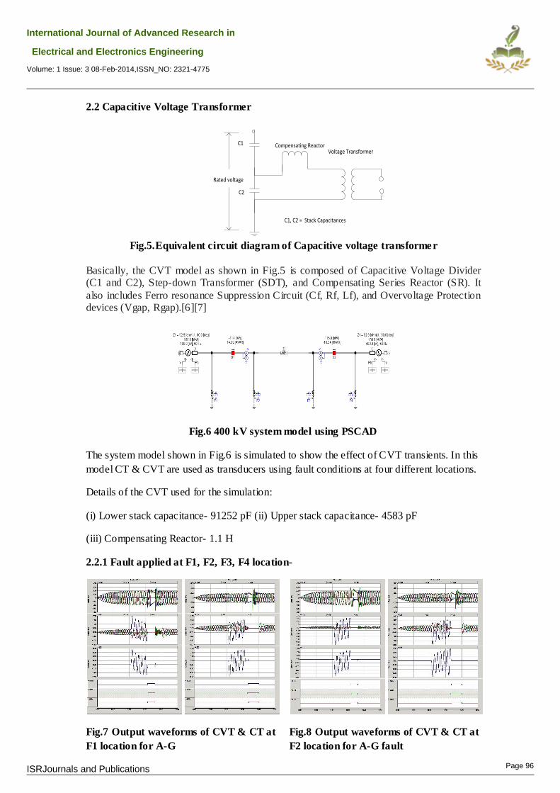
2.2 Capacitive Voltage Transformer
Rated voltage
C1
C2
Voltage TransformerCompensating Reactor
C1, C2 = Stack Capacitances
Fig.5.Equivalent circuit diagram of Capacitive voltage transformer
Basically, the CVT model as shown in Fig.5 is composed of Capacitive Voltage Divider (C1 and C2), Step-down Transformer (SDT), and Compensating Series Reactor (SR). It
also includes Ferro resonance Suppression Circuit (Cf, Rf, Lf), and Overvoltage Protection devices (Vgap, Rgap).[6][7]
Fig.6 400 kV system model using PSCAD
The system model shown in Fig.6 is simulated to show the effect of CVT transients. In this
model CT & CVT are used as transducers using fault conditions at four different locations.
Details of the CVT used for the simulation:
(i) Lower stack capacitance- 91252 pF (ii) Upper stack capacitance- 4583 pF
(iii) Compensating Reactor- 1.1 H
2.2.1 Fault applied at F1, F2, F3, F4 location-
Fig.7 Output waveforms of CVT & CT at
F1 location for A-G
Fig.8 Output waveforms of CVT & CT at
F2 location for A-G fault
ISRJournals and Publications Page 96

International Journal of Advanced Research in
Electrical and Electronics Engineering
Volume: 1 Issue: 3 08-Feb-2014,ISSN_NO: 2321-4775
Fig.9 Output waveforms of CVT & CT at
F3 location for A-G fault
Fig.10 Output waveforms of CVT & CT
at F4 location for A-G fault
From Fig. 7, 8, 9, 10, the severity of the CVT transients can be observed at different fault
locations which may lead to malfunctioning of relay.[8][10]
2.3 Case Study of CVT Ratio Error
According to the calculation of CVT ratio,
= 3636.36
For the purpose of testing 1kV input to the CVT was applied which must result an output of
275 mV. If it deviates from the standard value it may affect the performance of protective devices too. The results obtained as per the ratio error formula for the line under consideration have
been shown in above table. The results show that the ratio error of CVT exceeded the limits. Such kind of error may occur due to stack capacitor element failure & internal short
circuit due to internal flash over may be due to ageing effects. Therefore for the calculation of ratio error, it can be tabulated as in Table-2 Where
= Primary voltage
Table-2 Ratio error of CVT
at
CVT (kV)
at VT
(V) Ratio
Specified
Ratio
Error (% )
Specified
of CVT
for 1 kV
(mV)
Actual
of
CVT for 1
kV
Actual
ratio error
at the field
(% )
400 110 3636.36 5 275 291 5.81
400 110 3636.36 5 275 292 6.18
400 110 3636.36 5 275 295 7.27
400 110 3636.36 5 275 294 6.91
400 110 3636.36 5 275 292 6.18
ISRJournals and Publications Page 97

International Journal of Advanced Research in
Electrical and Electronics Engineering
Volume: 1 Issue: 3 08-Feb-2014,ISSN_NO: 2321-4775
400 110 3636.36 5 275 293 6.55
3, ROGOWSKI COIL
Generally rogowski coils are torroidal coils with air core (non-magnetic core). The absence of core makes them lighter in weight as compared to current transformer which is having iron core. The air core consideration in the rogowski coil construction makes the relative
permeability as unity ( ). Rogowski coil is placed around the current whose current is to be sensed as shown in Fig.11. [1][3][4]
Fig.11 Model of Rogowski Coil
The output of the rogowski coil can be given by the equation, [1]
Where, ‘i’ is the current which is to be sensed.
3.1 Case Study of Rogowski Coil
In practice two analog outputs are available across the output terminals of rogowski coil (provided from manufacturer), [11][12]
1. Standard AC output with an instantaneous value of 3Vrms full scale. 2. An optional DC output with the RMS value of measured current.
3.2 Application of Rogowski Coil in Power System
The application of rogowski coil for the induction heating application is coupled at the site
as shown in Fig.12. The converter along with rogowski coil acts as a transducer.
The installation of the converter needs the input supply of 230V AC. The relevant
parameters such as ratings are normally provided by the manufacturer. From which it is clear that the same rogowski coil can be coupled around the
transmission line. As the connection of current transformer needs the terminal block, in case of rogowski coil there is no need of such blocks. It can be directly connected with the help of shielded cable.
ISRJournals and Publications Page 98

International Journal of Advanced Research in
Electrical and Electronics Engineering
Volume: 1 Issue: 3 08-Feb-2014,ISSN_NO: 2321-4775
Fig.12 Application of rogowski coil for induction heating
3.3 Performance of Rogowski Coil at 50 Hz:
Table-3 provides results of the prototype installation for induction heating conductor application
Table.3 – Results at the site installed for induction heating application
Sr
No.
CURRENT ROGOWSKI INTEGRATOR
VALUE OUTPUT OUTPUT
1 10KA 10V 20mA
2 7.5KA 7.5V 16mA
3 5KA 5V 12mA
4 2.5KA 2.5V 8mA
5 0A 0V 4mA
4. CONCLUSION
From the results performance characteristics as shown in respective tables it is apparent
that rogowski coils overcome most of the limitations of the existing devices such as CTs & CVTs. Further rogowski coils being air core the problem of saturation doesn’t arise. Thus, rogowski coils are found to give effective devices for sensing the signals to relays. The
application of rogowski coil is proposed for the over-current relay in upcoming research.
5,REFERENCES:
[1]. Practical Aspects of Rogowski Coil Applications to Relaying , Special Report,
September 2010, Sponsored by the Power System Relaying Committee of the IEEE Power
Engineering Society
[2]. Dr. Dharshana Muthumuni, Lisa Ruchkall and Dr. Rohitha Jayasinghe “Modeling
Current Transformer (CT) Saturation for Detailed Protection Studies” Pulse 2011, pp 1-5,
HVDC Research Centre, Manitoba, Canada.
ISRJournals and Publications Page 99

International Journal of Advanced Research in
Electrical and Electronics Engineering
Volume: 1 Issue: 3 08-Feb-2014,ISSN_NO: 2321-4775
[3]. Lj. A. Kojovic, “Comparative Performance Characteristics of Current Transformers
and Rogowski Coils used for Protective Relaying Purposes” IEEE, Power Engineering
Society General Meeting, 2007, pp 1-6.
[4]. Veselin Skendzic, Bob Hughes “Using Rogowski Coils inside Protective Relays”
IEEE, Conference for Protective Relay Engineers, 2013, pp 1-10
[5]. Alstom, Network Protection & automation guide, 2011 edition
[6] Investigation of Transient Performance of Capacitor Voltage Transformer (Cvt),
Journal - The Institution of Engineers, Malaysia (Vol. 71, No.2, June 2009), PP-44-50, Dr
Saad Mekhilef, Mr. Cheng Hock Lim and Dr Ab. Halim Abu Bakar
[7]. IEC Capacitive & Coupling Capacitor Voltage Transformers (CVT & CCVT) guide,
General Electric, 2013
[8]. D. Hou and J. Roberts, “Capacitive Voltage Transformers: Transient Overreach
Concerns and Solutions for Distance Relaying”, 22 Annual Western Protective Relay
Conference, Spokane, WA, USA, October 24 - 26, 1995.
[9]. Using Rogowski coils for transient current Measurements by D. A. Ward and J. La T.
Exon, Engineering Science And Education Journal June 1993
[10]. Where did those transients come from and how are we going to handle them? A fresh
look at CCVT transient’s phenomena, Roger A. Hedding
[11]. Improved Performance in Current Measurement of Rogowski Coil in Power System,
Ashish S. Paramane, Dr. P.K.Katti International Conference at Asia Pacific Institute of
Technology (ICACCT-2013) ISBN:978-93-83083-38-1, PP:183-188.
[12]. Rogowski Coil- A Novel Transducer for Current Measurement, Ashish S. Paramane,
Avinash N. Sarwade, Pradeep K. Katti, Jayant G. Ghodekar,, in press, 6 th International
Conference on Power System Automation & Protection, by Central Board of Irrigation &
Power, India with CIGRE.
6,BIOGRAPHY
Mr. Ashish S. Paramane is pursuing 2nd year in M. Tech-Power System Engg. at Dr. Babasaheb Ambedkar Tech. University, Lonere- Maharashtra. He has completed his B. Tech degree in Electrical Engg. at Dr.Babasaheb
Ambedkar Tech. University, Lonere- Maharashtra. His area of interest is in power system protection.
Dr P. K. Katti graduated from Mysore University’s degree in Electrical
Engineering (Power) from BIET-Davanagere in 1985. He obtained
M.E.(Control System) from Govt. College of Engineering of Pune
University in 1991. He obtained Ph. D in Energy system from VNIT,
Nagpur India in 2007.
He has a wide teaching experience, and presently working with Dr.
Babasaheb Ambedkar Tech. University, Lonere, India as professor and Head in the Dept.
of Electrical Engg. He has guided projects at U.G., P.G. & Ph.D. research level.
Powered by TCPDF (www.tcpdf.org)
ISRJournals and Publications Page 100